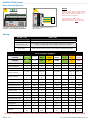
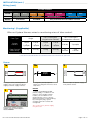
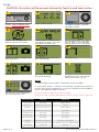
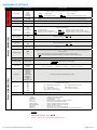
1
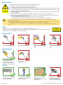
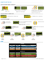
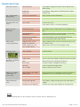
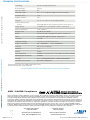
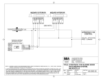
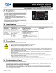
ENGLISH LZR-MICROSCAN Stand-Alone, Door Mounted, Safety Sensor for Automatic Swing Doors (US version) DESCRIPTION 2 6 1 5 3 8 7 9 4 1. tilt adjustment 2. sensor connection ports 3. sensor LED 4. end caps 5. optical window 6. plug-n-play ports INCLUDED KIT COMPONENTS 7. adjustment knob 8. LCD 9. hub LEDs REQUIRED TOOLS DESCRIPTION PART NUMBER SINGLE1 PAIR/DE2 TOOL Left LZR-microscan Sensor 10LZRMICROLEFT 1 2 Power Drill Right LZR-microscan Sensor 10LZRMICRORIGHT 1 2 Tape Measure LZR-microscan Hub 10LZRMICROSCANHUB 1 1 Magnetic Phillips #0 Master Sensor Harness 35.1326 1 2 Phillips #2 Slave Sensor Harness 35.1327 1 2 1/8” Drill Bit Door Control Harness 20.5222 1 2 5/16” Drill Bit System Harness 20.5304 1 1 Eagle Harness 20.5069 1 1 Power Supply Harness 20.5095 1 1 Home Switch (Surface Mount) 50.5283 1 2 Door Loop / Cap Kit 70.0202 / 50.0078 1 2 On / Off / Hold Open Switch Jumper 20.5310 1 1 Left Pass-Through Sensor Endcap 41.7922 1 2 Right Pass-Through Sensor Endcap 41.7923 1 2 3/8” Drill Bit 1/2” Drill Bit Pencil Center Punch / Hammer Wire Nuts Wire Snips Wire Fish MOUNTING KITS Sensor Spacer 70.5554 1 2 Spacer Mount Screws 50.0048 2 4 DESCRIPTION PART NUMBER Sensor Mount Screws (Metal) 50.1818 2 4 Narrow Frame Door 10MICROSCANMOUNT Glass / Fire Door 10MICROSCAN-Y Sensor Mount Scews (Wood) 50.5282 2 4 Endcap Screws 41.8632 4 4 NOTES: 1: Single Door Kit (10LZRMICROSCAN1) Velcro Tabs 50.0046 2 2 LZR-microscan Mounting Template 75.5754 1 1 LZR-microscan User’s Guide 75.5753 1 1 Power Supply 30.5558 1 (Universal3 ONLY) 1 (Universal3 ONLY) On / Off / Hold Open Switch 10DOORSWITCH 1 (Universal3 ONLY) 1 (Universal3 ONLY) 75.5753.02 LZR-MICROSCAN 20140107 2: Pair/Dual Egress Door Kit (10LZRMICROSCAN2) 3: Universal Single Door Kit (10LZRMICROSCAN1U) and Univeral Pair/Dual Egrees Door Kit (10LZRMICROSCAN2U) Page 1 of 12 PRECAUTIONS ! • • • Shut off all power going to header before attempting any wiring procedures. Maintain a clean & safe environment when working in public areas. Constantly be aware of pedestrian traffic around the door area. Always stop pedestrian traffic through the doorway when performing tests that may result in unexpected reactions by the door. ESD (electrostatic discharge): Circuit boards are vulnerable to damage by electrostatic discharge. Before handling any board ensure you dissipate your body’s ESD charge. Always check placement of all wiring before powering up to ensure that moving door parts will not catch any wires and cause damage to equipment. Ensure compliance with all applicable safety standards (i.e. ANSI A156.10) upon completion of installation. DO NOT attempt any internal repair of the components. All repairs and/or component replacements must be performed by BEA, Inc. Unauthorized disassembly or repair: 1. May jeopardize personal safety and may expose one to the risk of electrical shock. 2. May adversely affect the safe and reliable performance of the product resulting in a voided warranty. The device should not be used for purposes other than its intended use. All other uses cannot be guaranteed by the manufacturer of the sensor. The installer of the door system is responsible for carrying out a risk assessment and installing the sensor and the door system in compliance with applicable national and international regulations and standards on door safety. The manufacturer of the sensor cannot be held responsbile for incorrect installations or inappropriate adjustments of the sensor. LASER IR laser (Class 1); wavelength 905 nm; max. output pulse power 35 W CAUTION: Use of controls or adjustments or performance of procedures other than those specified herein may result in hazardous radiation exposure INSTALLATION Avoid extreme vibrations. Do not cover the sensor. Avoid moving objects and light sources in detection zone. Avoid highly reflective objects in the detection zone. Always test the proper operation of the installation before leaving the premises. The warranty is void if unauthorized repairs are made or attempted by unauthorized personnel. MAINTENANCE It is reccommended to clean the opitcal parts at least once per year or more if required due to environmental conditions. Do not use abrasive cleaning components. SAFETY The door conrol unit and the door header must be correctly grounded. Page 2 of 12 Only trained and qualified personnel may install and setup the sensor. 75.5753.02 LZR-MICROSCAN 20140107 IMPORTANT: In order to guarantee proper installation, instructions must be followed in order! Verify operation/functionality of door control and operator prior to system installation. PREPARATION Hub 1 Install hub in door header, centered and in an easily accessible location. 2 Plug System Harness into hub port labeled System. Do not plug in any other harnesses. Sensors 1 Determine on which side of door Door Loop will be installed and cut to shortest length to avoid loop in detection zone. 4 2 Take sensor to be mounted on loop side and remove Blank Endcap closest to door hinge 1. 5 3 Route Master Sensor Harness through Door Loop. NOTES: 1: For left sensor, remove left Blank Endcap or for right sensor, remove right Blank endcap. 2: Pull extra Master Sensor Harness slack through Door Loop (away from sensor) before tightening endcap screws. Plug Master Sensor Harness into sensor at closest port. Affix Door Loop to sensor with Pass-Through Endcap and three (3) screws 2. 75.5753.02 LZR-MICROSCAN 20140107 Page 3 of 12 INSTALLATION Sensors Refer to mounting template for full mounting instructions! 1 2 LEFT MOUNT DISTANCE FROM TOP OF DOOR sensor mounting 1/8 “ wire passage 5/16 “ microscan * Scan for Product Info 3 MOUNTING INSTRUCTIONS NOTES: Mount sensors as close to top of door and as close to hinge of door as possible. Spacer required for applications with hardware extending across width of door and protruding more than 2 in. DISTANCE FROM EDGE OF DOOR MOST BUTT HUNG MOST CENTER PIVOT * * For thin frame aluminum doors, mounting arm kit may be used. When using mounting arm kit, do not use this template. STEP 1: SURVEY BOTH SIDES OF DOOR TO DETERMINE APPROPRIATE MOUNTING LOCATION (DISTANCE FROM PIVOT EDGE AND DISTANCE FROM TOP OF DOOR), TAKING INTO ACCOUNT FRAME CLEARANCE, FINGER GUARD, DOOR ARM, ETC. * spacer mounting 1/8 “ MOUNTING HEIGHT RANGE: 6’7” - 8’2” Reference LZR-microscan User’s Guide 75.5753 for full installation instructions 75.5754.01 20140107 LZR-microscan Mounting Template STEP 2: FOLD ALONG APPROPRIATE HORIZONTAL AND VERTICAL LINES AND ALIGN WITH PIVOT EDGE AND TOP OF DOOR STEP 3: MARK AND DRILL THREE (3) HOLES * STEP 4: FLIP TEMPLATE AND REPEAT FOR RIGHT SENSOR * When using spacer, drill any two (2) spacer mounting holes and wire passage hole instead of sensor mounting holes . When using optional mounting holes it may be neccessary to remove end caps or sensor from base. Use Mounting Template to position each sensor correctly. Check for obstructions/clearance. 4 Mount sensors (using appropriate screws) by following instructions on Mounting Template. 7 Align Mounting Template, mark and drill holes 1. Repeat on both sides of door. 5 Run Slave Sensor Harness through door. 6 Plug in Slave Sensor Harness at the upper most port on sensor. Install Door Loop: drill 1/2” passage hole in header and jamb, route Master Sensor Harness, install cap. NOTES: 8 1. Spacer required for applications with door hardware extendeing across width of door and protruding more than 2 in. Do not apply sensor covers until system is fully operational. Do not adjust tilt angle. Plug Master Sensor Harness into hub port labeled Door A Sensors If necessary, repeat steps 1-7 for second door leaf using hub port Door B Sensors. Home Switch1 NOTES: 2 1: Any dry contact home switch or auxiliary switch may be used and must be closed when door is closed. Install Home Switch at desired location. Page 4 of 12 HUB Home Switch Home Switch 1 Wire nut white Home Switch wires to orange wires of System Harness plugged into hub2. 2: For simultaneous pairs or dual egress doors, two (2) Home Switches must be wired in series with orange wires of System Harness plugged into hub. Switch must “break” as soon as door begins to open. 75.5753.02 LZR-MICROSCAN 20140107 INSTALLATION (cont.) Periphials All periphial devices, including safety, activation, security, and logic modules should be wired directly to hub and not to door control. On / Off / Hold Open Switch If using an existing on / off / hold open switch, plug On / Off / Hold Open Switch Jumper into hub port labled On / Off / Hold Open and wire nut red and black wires together, or if desired, splice existing switch into Jumper. 1 Determine mounting location, apply mounting template, drill holes. FUNCTION JUMPER WIRES on red jumped to black hold open black jumped to white off none 2 Route On / Off / Hold Open Switch harness and plug into hub port labeled On / Off / Hold Open. Eagle (Optional) 1 Install Eagle(s). For complete installation instructions refer to BEA User’s Guide 75.0058. 2 Plug Eagle Harness(es) into hub port labled Motion 1 and, if applicable, Motion 2. Push Plates (Optional) Install push plate(s). For complete installation instructions refer to the appropriate BEA User’s Guide1. NOTES: 2 COM NO Multiple push plates can be paralleled to grey wires of System Harness. HUB Push Plate 1 Wire nut push plate wires (COM and NO) to grey wires of System Harness plugged into hub. 75.5753.02 LZR-MICROSCAN 20140107 Page 5 of 12 INSTALLATION (cont.) Door Control Harness 1 NOTES: 2 If door system utilizes independent door controls, repeat steps 1-2 for the second control. Do not use door control sync cable. Door Control Plug Door Control Harness into hub port labeled Door Control A. For dual egress doors with independent stall, two (2) Door Control Harnesses must be used. Wire Door Control Harness to door control. Wiring DOOR TYPE HUB PORT single always use DOOR CONTROL A hub port simultaneous pair from header (access cover) side, left door uses DOOR CONTROL A hub port and right door uses DOOR CONTROL B hub port dual egress from header (access cover) side, whichever door is pushed (right door) during Teach In process uses DOOR CONTROL B hub port DOOR CONTROL HARNESS WIRE COLOR: Green White Green/ Black Yellow/ Black White/ Black Green/ Red Yellow/ Red White/ Red SIGNAL: ACT NO ACT COM SAFE NO SAFE NC SAFE COM STALL NO STALL NC STALL COM 15 16 Besam 300 / ETIK 13 12 11 12 Besam MP/CUP 3 4 9 4 5 4 Besam SM900/CU2 1 3 2 3 7 3 Besam SW100 CU-ESD 2 CU-ESD 1 CU-ESD 4 CU-ESD 1 EXU-SA 3 EXU-SA 1 Besam SW200 CU-200 2 CU-200 1 CU-200 4 CU-200 1 EXU-SA 3 EXU-SA 1 Door O Matic Yellow Grey Blue Grey Purple Grey Dorma 400/700 TRIG GND PRES GND SWING GND Gyrotech 300/400 Black Red White Red White Red 6 Black 5 Red 4 White 5 Red 3 Violet 5 Red 2 3 4 3 10 3 ACT RTN SAF 1 RTN SAF 2 RTN Green White Red White Yellow White Gyrotech MAG Horton 4190 Hunter Keane Monroe K Record 6000/8000 Stanley L Stanley MP Stanley 521 Tormax 2 1 8 4 Orange Yellow Red Yellow Blue 10 Yellow 11 2 8 7 8 7 8 TB4-4 TB4-3 TB3-8 TB3-7 TB3-4 TB3-3 Input C #2 Input C #1 Safety B #2 Safey B #1 Safety A #2 Safety A #1 If using independent stall, stall wires on both Door Control Harnesses must be used. Page 6 of 12 75.5753.02 LZR-MICROSCAN 20140107 INSTALLATION (cont.) Wiring (cont.) SYSTEM HARNESS WIRE COLOR: Grey Grey Orange Orange SIGNAL: Knowing Act Activation Home Switch NOTES: Push Plates Provided Purple Purple Blue Monitoring Door 1 Blue Monitoring Door 2 Only used with monitored door controls Monitoring* (if applicable) Wire nut System Harness wires to monitoring wires of door control: Door Type: Single Pair / Dual Egress (single/master control) Pair / Dual Egress (independent controls) System Harness: 1 blue + 1 purple 1 blue + 1 purple 1 blue + 1 purple 1 blue + 1 purple 2 blues 2 purples Door Control Monitoring: 1st leg 2nd leg 1st leg 2nd leg 1st Control 2nd Control * SEE APPLICATION NOTES OR CONTACT BEA FOR TECHNICAL SUPPORT Power If using installer provided power supply, wire nut output of power supply to Power Supply Harness. 3 Plug Power Supply or Power Supply Harness into hub port labeled Power. Power Supply If using BEA provided power supply, cut plug off of harness and strip wires1. Power Supply 2 110 V Soruce 1b Pwr Sup Harness Power Supply 1a Wire nut input of power supply to 110V power source. NOTES: 1: When using BEA provided power supply, if a NEMA 5-15R outlet is not available in door header, cut off NEMA 5-15P plug and wire nut to 110V AC observing polarity and grounding. By cutting off plug, system changes from UL Listed to UL recognized. Any 15W Class II power supply may be used. 75.5753.02 LZR-MICROSCAN 20140107 Page 7 of 12 SETUP CAUTION: No safety will be present during the Teach In and Learn cycles. 1 2 Program hub according to desired settings. Menu 1 (Basic) items MUST be programmed. 4 3 Return to home screen. Push and hold adjustment knob for three (3) seconds, until blue LED begins to flash. 5a Network icon will appear for approximately five (5) seconds. 6 5b “CLEAR AREA” will display and countdown will begin. Clear area around door on both sides. For dual egress doors, Push Door icon will display. Push right door (Door B) open at least 10 degrees1. 7 Automatic teach in will begin with door closed learn. 9 8 Door opening learn. Door will open automatically. Door open learn. 11 10 Door closing learn. After Teach In is complete a floppy disk will be displayed. 12 NOTES: Hour glass will be displayed for approximately thirty (30) seconds while all learn data is saved. 1: For Dual Egress Reverse Doors, contact BEA Technical Support. 2: Verify Home Switch is “making” and “breaking” by observing orange LED on hub. Home Switch should be set as sensitive as possible and should break within a few degrees of door movement. Once Teach In is complete, LCD displays home screen, Blue LED is off, and orange LED is on2. Page 8 of 12 Be sure to walk test door after setup is complete. Perform new learn anytime door operator, control, sensor, or hub is adjusted. TEACH-IN STAGE HUB LED SENSOR LED Prior to Learn blue flashing red/green flashing Network Icon blue flashing & orange solid red solid Clear Area blue flashing & orange solid red/green flashing Door Closed Learn blue flashing & orange solid green flashing Door Opening Learn blue flashing green flashing Door Open Learn blue flashing green flashing Door Closing Learn blue flashing green flashing Floppy Disk blue flashing & orange solid green solid -> green flashing Hour Glass blue flashing & orange solid green flashing -> red solid -> red/green flashing Learn Complete orange solid green solid 75.5753.02 LZR-MICROSCAN 20140107 OVERVIEW OF SETTINGS Menu 3 (DIAGNOSTICS) Menu 2 (ADVANCED) Menu 1 (BASIC) MENU LCD DISPLAY PARAMETERS DoorType Undefined Single Pair DualEgr InDualEgr DESCRIPTION Type of door system on which sensors are installed Single: Single Door DualEgr: Dual Egress Doors Pair: Pair of Doors InDualEgr: Independent Dual Egress Doors DetectZoneA 24 - 48 Distance (in inches) from sensor LED to leading edge of Door A [round down] DetectZoneB 24 - 48 Distance (in inches) from sensor LED to leading edge of Door B [round down] Guiderail 0 - 60 Guiderail height from floor (in inches) Monitoring Off Safe Stall Safe&Stall Act Act&Stall Off: No Monitoring Safe: Monitoring of Safety Signal Stall: Monitoring of Stall Signal Safe&Stall: Monitoring of Safety & Stall Signals Act: Monitoring of Activation Signal Act&Stall: Monitoring of Activation & Stall Signals KnowingAct Off On Turns Knowing Act Off or On Act:HoldTime 1 - 5 - 30 Time activation relay will be held after loss of detection (in seconds) PushNGo Off On Turns Push-And-Go Off or On NotCloseTime 5 - 30 Time required for door to reach “Closed” from “Open” or “Manual” before switching to “NotClosed” (in seconds) AdvanceSafe Off On Act:Dist 12 - 24 - 48 Door closed detection distance of Approach Sensor(s) (in inches) MonitorLogic ActiveLow ActiveHigh ActiveLow: 0V requests monitoring ActiveHigh: > 0V requests monitoring Safe:Dist Deep Medium Limited DispDoor Closed Opening Open Closing NotClosed Manual HoldOpen Off AdvanceSafe DispSens A1 A2 PP MO S1 S2 HM DispPos % Type of monitoring Type of safety provided while door(s) is/are currently open due to manual operation (or stack pressure Off: Allows door(s) to activate, via motion sensor or push plate On: Prevents door(s) from activating, via motion sensor or push plate Door closed detection distance of Safety Sensor(s) Deep: 4 curtains Medium: 3 curtains Limited: 2 curtains Displays current position/state of door Displays active devices A1: Approach microscan 1 PP: Push Plate S1: Safety microscan 1 HM: Home Switch Closed % A2: Approach microscan 2 MO: Motion Sensor S2: Safety microscan 2 Displays opening position (0% = full closed, 100% = full open relative to learn cycle) ID#... .................................unique ID number Config.. .............................configuration part number Software.. ..........................software part number ErrorLog. ............................last 20 errors ZIP. .................... ................all parameter settings in zipped format HubTemp............................operating temperature of hub PowerSupply..... .................supply voltage at power connector OperatingTime....................power duration since first startup ResetLog... .........................delete all saved errors Admin.. .............................enter code to access admin mode Network.............................sensor info: software, configuration, mounting location NOTES: Default parameters are in BOLD. Menu 1 (Basic) items MUST be programmed! 75.5753.02 LZR-MICROSCAN 20140107 Page 9 of 12 HOW TO USE THE LCD DISPLAY DURING NORMAL OPERATION Safety Activation Stall (door 1 & 2) Negative display = active output To adjust contrast, push and turn the grey button simultaneously. Opposite for reverse logic During normal operation only. FACTORY VALUE VS. SAVED VALUE displayed value = factory value displayed value = saved value NAVIGATING IN MENUS Push to enter the LCD-menu Scroll menu items Select your language before entering the first LCD-menu. Available for the first 30 seconds after power-on of the hub. Select Back to return to previous menu or display. Select More to go to the next level: - basic - advanced - diagnostics CHANGING A VALUE current value is displayed SCROLL MENU UP-DOWN PUSH TO SELECT PARAMETER more values are displayed new value is displayed SCROLL VALUES UP-DOWN PUSH TO SAVE NEW VALUE LEDS HUB LED COLOR SIGNAL DESCRIPTION Blue Learn Learn in progess or Learn required White Tracking Door position & detection zone tracking Orange Home Switch Home Switch closed (door closed) COLOR SIGNAL Green Operational Sensor operational Red Detection Sensor in detection Orange Error Sensor in error...reference hub LCD SENSOR LED Page 10 of 12 DESCRIPTION 75.5753.02 LZR-MICROSCAN 20140107 TROUBLESHOOTING Hub LCD is not on No input power Verify power supply connection, do not power from door control Bad power Verify power supply, power from BEA power supply Faulty hub Replace hub No “CLEAR AREA” during setup Sensors not discovered Verfiy sensor harness connection No Floppy Disk after setup Learn failed Perform new learn Door(s) will not open/close Door control issue Verify door control is operational with nothing wired to it No inputs/outputs connected Verify all connections are secure (sensors and On/Off/ Hold Open swtich must be connected) Knowing Act turned on Turn Knowing Act off or use knowing act devices Verify home switch is functioning properly Incorrect wiring Verify wiring from hub to door control Approach side sensors going into detection Adjust approach side sensors Activation Distance and/ or motion sensor Home switch not “making” at door closed Adjust home switch and verify proper wiring Cap LCD screen Learn required Perform relearn Orange flashing LED on Sensor - reference Hub for error height/angle sensor mounted too high or adjusted too close to door EDPS door did not reach full open during learn BUS config number of doors configured incorrectly boundary sensor masked by foreign object lost message loose or broken sensor harness Door never reaches “Hold Open” or “Off” states Not using On / Off / Hold Open Switch Wire existing on / off / hold open switch to jumper or plug BEA On / Off / Hold Open Switch into hub Hub Environment error Voltage too high/low Verify power supply voltage, power from BEA power supply Temperature too high/low Envionment may be too cold/hot for hub operation Door(s) keep recycling (ghosting) NOTES: Troubleshooting tools can be viewed on Hub LCD within Menu 3 (DIAGNOSTICS). 75.5753.02 LZR-MICROSCAN 20140107 Page 11 of 12 ©BEA|OriginalInstructions|75.5753.02LZR-MICROSCAN20140107 PLEASE KEEP FOR FURTHER USE - DESIGNED FOR COLOR PRINTING TECHNICAL SPECIFICATIONS Technology: laser, time-of-flight measurement Detection mode: presence Max. door width: 48” Mounting Height: 6’ 7” - 8’ 2” (for greater heights contact Tech Support) Remission factor: > 2% Angular resolution: 2.56 ° Testbody: 28” (H) x 12” (W) x 8” (D) according to UL325 Emission characteristics: IR laser: wavelength 905 nm; max. output pulse power 35 W (CLASS 1) Supply Voltage: 12-24 VAC +/-5% / 12-30 VDC +/- 10% (15 W Class II) Power Consumption: 15 W maximum Response time: typ. 40 ms; max. 80 ms Output: 4 electro-mechanic relays (galvanic isolated - polarity free) Input: 2 optocouplers (galvanic isolated - polarity free) Test Input *: 8-15 VDC Temperature Range: -13 °F to +121 °F (-25 °C to +55 °C) Degree of Protection: Hub - IP20/NEMA 1 Humidity: 0-95 % non-condensing Vibrations: <2G Material: PC/ASA Norm Conformity: EN 60825-1-Eye-safety class 1 IR laser (905 nm), UL325, UL6730 Mounting agnle (rotational): 35° fixed Tilt angle: 0° to 5° (for angles less than 5° contact Tech Support) Pollution on front screens: max. 30 %; homogenous Sensor - IP53/NEMA 3 Specifications are subject to change without prior notice. All values measured in specific conditions. * SEE APPLICATION NOTES OR CONTACT BEA FOR TECHNICAL SUPPORT ANSI / AAADM Compliance AAADM American Association of Automatic Door Manufactures Upon completion of the installation or service work, at a minimum, perform a daily safety check in accordance with the minimum inspection guidelines provided by AAADM. Provide each equipment owner with an owner’s manual that includes a daily safety checklist and contains, at a minimum, the information recommended by AAADM. Offer an information session with the equipment owner explaining how to perform daily inspections and point out the location of power/operation switches to disable the equipment if a compliance issue is noted. The equipment should be inspected annually in accordance with the minimum inspection guidelines. A safety check that includes, at a minimum, the items listed on the safety information label must be performed during each service call. If you are not an AAADM certified inspector, BEA strongly recommends you have an AAADM certified inspector perform an AAADM inspection and place a valid inspection sticker below the safety information label prior to putting the equipment into operation. Page 12 of 12 24/7 Technical Support: 1-800-407-4545 Customer Service: 1-800-523-2462 General Technical Questions: [email protected] Technical Documentation: www.beasensors.com 75.5753.02 LZR-MICROSCAN 20140107