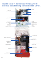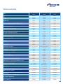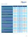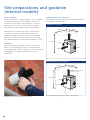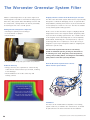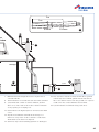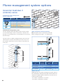
1
Technical and Specification Information
Greenstar Heatslave II Internal Series
Greenstar Heatslave II External Series
Greenstar Heatslave II
oil-fired condensing
combi boiler range
Includes
ErP
ratings
1
Worcester and you. Making a difference.
As part of the Bosch Group, Worcester
is able to provide comprehensive support
products are designed and manufactured to
and advice from designing system layouts
provide customers with the highest levels of
through to installation.
quality and reliability which are synonymous
with the Bosch name.
Worcester is dedicated to providing high
performance, energy efficient heating
Worcester is a part of Europe’s largest
and hot water systems for a wide range
supplier of heating products and with our
of installations. Our oil manufacturing
UK-based resources as well as the Bosch
heritage stretches back to the foundation of
Group's global infrastructure, we can offer
the company in 1962 and during this period
you the value-added solutions you deserve.
we have built a reputation for manufacturing
Worcester employs a nationwide network of
products which offer the end user the
Service Engineers and technically trained
highest levels of quality and reliability.
Field Sales Managers, supported by an
experienced technical services team which
2
The reception and main entrance
at our Worcester headquarters
Contents
Page
The Greenstar condensing combi boiler range
4-5
Why choose Worcester?
6
Heatslave II designed with installation and servicing in mind
7
Key features of the range
8-9
“At Worcester we recognise the vital role you
Optional plug-in controls
10 - 11
play in the specification and installation of
ErP easy as ABC
12 - 13
energy efficient appliances in homes across
Inside story – Greenstar Heatslave II
14 - 15
Inside story – Greenstar Heatslave II External
16 - 17
Site preparations and guidance
18 - 22
order to deliver only the best solutions to your
Installation requirements
23 - 27
customers’ requirements.”
The Worcester Greenstar System Filter
28 - 29
Condensate pipework
30 - 31
The Worcester CondenseSure auxiliary siphon
32 - 33
Horizontal and vertical flue terminal positioning
34 - 35
Horizontal fluing options (internal models)
36 - 37
Vertical fluing options (internal models)
38 - 39
Horizontal fluing options (external models)
40
Plume management positioning and system options
41 - 43
Conventional flue
44
Oilfit flexible flue liner
45 - 46
Accessories
47 - 49
Worcester training
50 - 52
After-sales
53
the UK. We will continue to invest in our
products, people, facilities and added value
services to ensure you have all you require in
Carl Arntzen,
Managing Director,
Bosch Thermotechnology Ltd.
3
The Greenstar Heatslave II
condensing combi boiler range
Worcester has always understood that, as the market
The latest generation Heatronic 4i controls bring advanced
leader for heating and hot water, it is our responsibility to
and precise control to both the internal and external
pave the way for future standards of quality, reliability and
models, giving the installer and homeowner a vast range
innovation. This common purpose and vision has been
of features, allowing the heating system to be as efficient
held for over 50 years, with Worcester pioneering domestic
and flexible as possible. They also enable integration with
oil-fired boilers since 1962. The Greenstar oil-fired range
our range of intelligent plug-in controls, enabling further
has been expertly designed using the latest cutting-edge
efficiency gains to be made.
boiler technology to deliver exceptional performance over a
wide range of applications. The appliance is manufactured
Every appliance is operationally tested before it leaves
at Clay Cross in Derbyshire with Bosch production
the factory as part of Worcester's rigorous quality
processes and systems.
control procedure.
The launch of the Greenstar Heatslave II ranges
Highly efficient condensing technology
marks the latest critical step for our company, with
The secondary condensing heat exchanger of the
Worcester building upon the valuable feedback that our
Greenstar range extracts more energy from the oil and,
installers and users have provided to inspire a range of
when compared with a non-condensing boiler, can cut
boilers which provide flexibility for the installer and ease
heating and hot water bills by over £400 a year†. All
of use for the customer.
Greenstar condensing boilers are able to deliver this
energy-saving performance by extracting additional latent
On-demand hot water
heat from the exhaust gases – a highly efficient use of
An instantaneous supply of hot water is available from the
energy which significantly reduces carbon dioxide emissions
plate heat exchanger which rapidly transfers heat from
into the atmosphere.
the Heatslave II's thermal store. DHW flow rates of up to
22 l/min can be achieved and the 18/25 and 25/32 models
are suitable for properties with more than two bathrooms.
†Source: Energy Saving Trust: Based on replacing a G-rated oil-fired boiler with an A-rated oil-fired condensing boiler
and a full set of controls in a typical 3 bedroom semi-detached home with an average oil price of 6.02p/kWh.
4
Kitchen courtesy of Alno Kitchens.
The Greenstar Heatslave II combi range at a glance
Heatslave II
12/18
18/25
25/32
7 731 600 047
7 731 600 048
7 731 600 049
ErP Seasonal space heating
energy efficiency class
A / 91%
A / 90%
A / 91%
ErP Water heating energy
efficiency class
B
B
B
Part no.
89.4%
89.2%
89.0%
Min
12kW
18kW
25kW
Max
18kW
25kW
32kW
15l/min
18l/min
22l/min
855 x 520 x
600mm
855 x 520 x
600mm
855 x 520 x
600mm
9
9
9
9
9
9
Riello RDB
Riello RDB
Riello RDB
12/18
18/25
25/32
7 731 600 050
7 731 600 051
7 731 600 052
ErP Seasonal space heating
energy efficiency class
A / 91%
A / 90%
A / 91%
ErP Water heating energy
efficiency class
B
B
B
89.4%
89.2%
89.0%
Min
12kW
18kW
25kW
Max
18kW
25kW
32kW
15l/min
18l/min
22l/min
950 x 640 x
770mm
950 x 640 x
770mm
950 x 640 x
770mm
9
9
9
Riello RDB
Riello RDB
Riello RDB
SEDBUK 2009 efficiency
Output kW
DHW flow rate
Dimensions
(h x w x d)
Conventional flue
Room sealed flue
Oil burner
Heatslave II External
Part no.
SEDBUK 2009 efficiency
Output kW
DHW flow rate
Dimensions
(h x w x d)
Balanced flue
Oil burner
5
Why choose Worcester oil?
Given the competitive nature of the heating industry, Worcester
know that installers have an important decision to make when it
comes to selecting the best product for their customers. Many
installers are loyal to the Worcester brand and recognise the
By appointment to
Her Majesty The Queen
Boiler Manufacturer
Worcester, Bosch Group T/A
Bosch Thermotechnology Ltd.
importance of the technical support and training Worcester offers.
At Worcester, we pride ourselves on the hard work that goes on
behind the scenes to make sure you and your customers benefit
from much more than the best in high-efficiency boilers and
renewable technologies.
For example, within the product reliability department, every
Worcester Greenstar oil boiler is tested. The testing procedure
ensures that every boiler has been put through its paces in the
most extreme of conditions to ensure they are robust enough to
stand up to the highest of demands and toughest of environments.
We collect information on each individual component when we
field trial our appliances, whilst also systematically noting any
feedback from the service engineer who worked on the boilers.
This information, along with responses from installers, is constantly
processed to ensure all technical observations can be acted upon
as a matter of urgency. It is this commitment that ultimately
9 out of 10
professional installers would choose
Worcester
“
for their own home”*
ensures Worcester products remain the best they can be.
Did you know?
• For testing purposes Worcester has its own formula to
on-site, Worcester has more quality control engineers
contains iron dust, quartz sand, hemp fibre and other
than salesmen.
contaminants which are commonly found in system
•
• As part of the global Bosch Group, Worcester has
water samples.
access to world leading resources, including a corporate
Test boilers are positioned on a shaker table for 3 hours
research department and access to the very latest
before being set to vibrate across a range of frequencies
manufacturing and product development processes.
to simulate 3,000 miles of worldwide transport.
• Parts in the hydraulic circuit complete 300,000 water
• Each new Worcester appliance design is ‘field trialled’
for at least 1 winter period. To benefit from winter
pressure cycles to ensure optimum performance
conditions all year round, outside of the British winter,
is achieved.
products are tested overseas.
• We have received a Royal Warrant in recognition of
supplying goods to Her Majesty, the Queen, an honour
we have held since 1992.
6
• With over 100 people in the quality control team
replicate contaminated heating system water. This mix
• Every boiler receives an end of line full functional test
before it leaves the factory.
• One in four oil boilers installed in the UK is a Heatslave.
*Source: Worcester Customer Satisfaction Index 2011
Greenstar Heatslave II designed with
installation and servicing in mind
In addition to our own extensive testing and research, we
Simple servicing
also listen and respond to installers as part of our product
The Heatslave II range has serviceability at its heart.
development programme.
Based on installer feedback, the Greenstar Heatslave II
As a result of such feedback, we have brought about the
has been created to make servicing as simple and quick as
following distinct features that benefit the installer.
possible, with the layout enabling an annual service to take
place completely from the front of the boiler.
Easy installation
The first thing that you will notice is that the Greenstar
Heatslave II models are up to 50kg lighter than the previous
Greenstar Heatslave. Look inside and you'll see there is
now a cross-firing burner, simplifying oil supply and the
expansion vessel is mounted at the front on a hinge,
allowing fluing to the left. The hydraulic connections have
been positioned on a diagonal plane at the left rear of the
boiler enabling quick and easy installation.
The expansion vessel moves 90º to allow full unhindered
access to the burner, and the primary heat exchanger
designed with ErP in mind, contains a one-piece primary
baffle which is manufactured in high-temperature-resistant
stainless steel, making them easy to clean and quick
to service.
Further improvements include an oil line which is run
through the cabinet, as well as an oil isolation valve which
mounts on an easy-to-access bracket on the right hand
side of the primary heat exchanger. There is space on the
bracket for the installation of a second oil isolation valve if
you are utilising a twin pipe system.
Finally, the Greenstar Heatslave II retains the internal
condensate trap from the previous models, which utilises
a simple condensate pipe connection. The height of
the trap removes the need for a condensate pump in
most instances.
The existing, simple-to-remove, mesh baffle design has
continued to be utIlised in the secondary heat exchanger.
The components on the modular hydraulic block will be
familiar to those servicing our gas-fired boilers. They offer
improved reliability and are easy to replace.
7
Key features of the range
On the primary On the secondary
heat exchanger* heat exchanger*
Greenstar Heatslave II boiler range
Greenstar Heatslave II External
Greenstar internal models are ideally suited for installation
Where space in the home is at a premium a Greenstar
around the home.
Heatslave II External boiler is the ideal solution.
The Greenstar Heatslave II internal boilers feature:
Whilst offering many of the operating features of Heatslave II
internal models, Heatslave II External boilers also feature:
•
• Cross-firing burner
• A robust, durable external cabinet that blends in with the
Renowned
Worcester
reliability
garden and allows for a long life expectancy
•
• Same class-leading footprint as previous Heatslave models, • IP45 Ingress Protection – protecting the boiler from water,
Installer-optimised hydraulic connections
creating less disturbance in replacement installations
• Front access for routine servicing, including a pivoting
expansion vessel for ease of access to the combustion
chamber and one-piece baffles
• Pre-wired electrical mains connection
• Easily accessible oil inlet valve
• Reduced boiler weight
• Modern cabinet design
• The option to add a range of digital programmers,
including RF options, to give fully automatic control,
eliminating the need for external wiring of a programmer
•
• A pre-wired mains lead with a plug allows easy isolation of
the boiler during maintenance
• A built-in frost thermostat which protects the appliance
from freezing
• An internal pull-out control panel which contains the boiler
heating and hot water temperature controls as well as a
lockout indicator, mode indicator and mode switch
• The same performance features as the internal counterparts
• All External combi boilers are now supplied complete
with flue.
Weather and load compensation options enabling the
boiler flow temperature to be varied in accordance with
Efficiency and environmental features
demand, allowing greater efficiency and comfort
• Excellent energy performance
• A design which has the ErP Directive in mind
• ErP ‘A’ rated for heating and ErP ‘B’ rated for
• A pre-heated thermal store which provides the user with
instant hot water
• Unique pull-out control panel with LCD display and
diagnostic information
• The Heatronic 4i boiler control unit intelligently responds
to heating and heat water demands, reducing burner
firings and transferring surplus heat from central heating
demands to the thermal store
•
• 5 year guarantee on Worcester primary heat exchanger*.
10 year guarantee on the plate heat exchanger*
8
dust and external elements
hot water
• The opportunity to improve SAP performance with
weather compensation
• 30ºC minimum heating return temperature for maximum
condensing efficiency
• ECO hot water mode
• Accepts pre-heated hot water from low carbon heating
technologies such as solar thermal and biomass.
*Subject to conditions
Operation
Applications
The Greenstar Heatslave II is supplied as standard suitable
• The outputs offered by the range ensures installation
for sealed primary water systems. The appliance contains
flexibility, making Greenstar oil-fired boilers ideally suited
an expansion vessel, 3bar pressure relief valve, pressure
to many sizes of domestic property
gauge and an automatic air vent.
• The Greenstar Heatslave II will accept pre-heated DHW
to 60ºC from sources such as solar and biomass. They
are ideally matched to our range of Greenskies solar
thermal panels.
Greenskies Solar-Lux,
Solar-Lifestyle and
Solar-Lito
Greenstar Heatslave II External model
Oil
These appliances are for use on 28 sec kerosene fuel only.
Fluing
The indoor appliance can be used with
Hot water mode
either a room sealed concentric flue or
With the appliance in a standby condition, i.e. the heatbank
conventional (open) flue. A flexi-flue liner kit is available to
at a temperature set by the hot water thermostat, when a
enable the appliance to be flued via a chimney. The room
demand for hot water is required the flow switch will
sealed flue ensures quiet operation.
energise the pump and circulate primary hot water around
the boiler and the plated water to water heat exchanger.
The external appliances utilise a balanced flue system in
The burner will automatically light to maintain the
order to minimise the risk of lockouts caused by heavy winds.
temperature of the heatbank.
A standard flue kit is included with every external boiler.
When hot water is no longer required, the appliance will
A plume management kit is available for both internal and
continue to operate until the heatbank has returned to
external boilers.
temperature. Priority is always given to the production of
domestic hot water.
Greenstar Oilfit – the easy-fit fluing solution
• Multiple fluing options with the ability to flue internal floor
There are two hot water modes on the appliance. In the
standing boilers from the top, rear or side and external
standard mode the burner fires soonest to keep the thermal
boilers from the rear and side
store temperature high, maximising hot water comfort. In
ECO mode the thermal store temperature is allowed to fall
more before the burner fires, saving fuel.
• Conventional flue via the adaptor kit or flexi-flue chimney
liner kit
• Room sealed flue lengths using 80/125mm dia. flue up to
8m vertically and 6m horizontally. Plume kit lengths to 5m
Central heating mode
When central heating is required, the diverter valve will
open and the pump will energise in order to circulate
primary water around the heating system. The burner will
automatically light and the radiators will heat up to the
• Quick-to-install push-fit connections and telescopic options
which form a gas-tight seal and in most cases eliminate the
need to cut the flue
• Easy-fit installation that requires no special tools when
fitting flue extensions, elbows and adaptors.
temperature set by the heating control thermostat.
Installation of a
Greenstar Oilfit
RS flue system
9
Keeping you and your customers
in control
The Greenstar Heatslave II features the revolutionary Heatronic 4i control unit which provides accurate and intelligent control
of the appliance. The control unit is discretely housed in a drawer with upward-facing controls for ease of adjustment.
The Greenstar Heatslave II
pull-out fascia with the
intuitive in-built display.
Easy-to-read and monitor
Weather and load compensation
The clear screen means system parameters, such as hot
To save energy and improve heating comfort, the Heatslave
water flow rate and heating flow temperatures, can be
II will accept compensating room and outdoor temperature
easily monitored by the installer during commissioning.
controls. For weather compensation, an outdoor sensor
can be combined with the Heatronic 4i’s in-built weather
Easy reset
compensation functionality. Load compensation is
Most boiler lockouts can be reset from a single button on the
provided by wiring the FR10 intelligent room thermostat
control unit. This is also the reset for burner lockouts, so the
to the boiler.
end user has no need to access the inside of the boiler.
Service menu
The simple-to-use engineers’ menu can check the operations
of various boiler components without the need to remove
the boiler front cover. Any problems can be easily identified
with diagnostic codes, narrowing the potential causes of
the problem.
ECO hot water mode
The Heatronic 4i has two hot water modes. Standard mode
prioritises maintaining the temperature of the slave tank,
maximising hot water performance. In ECO mode, to save
fuel, the temperature drop of the slave tank is increased,
meaning the burner fires less frequently to reheat the tank,
thus saving fuel.
10
As part of the Bosch Group, Worcester is committed to new product development, economical use of heating systems and
environmental protection. As part of this commitment, Worcester has a range of heating controls designed to enhance the
integral efficiency of our Greenstar Heatslave II range.
NEW Greenstar Comfort controls
Greenstar Comfort plug-in twin channel programmer – Part no. 7 733 600 003
• Simple menu navigation
• Heating programme visualisation bar
• 7-day time control for heating and hot water.
G
Greenstar
Comfort I RF wireless room thermostat
an plug-in twin channel programmer – Part no. 7 733 600 001
and
A the features of Comfort PLUS…
All
• No wiring required
• Reliable RF signal.
EFFICIENCY
+1%
Greenstar
Comfort II RF wireless programmable room thermostat
G
and plug-in RF receiver – Part no. 7 733 600 002
All the features of Comfort & Comfort I PLUS…
• 6 adjustable heating temperatures per day
• Set programme at the room thermostat
• Remote access to boiler diagnostic codes.
EFFICIENCY
+1%
Greenstar Comfort Wall Plate Kit – Part no. 7 733 600 039
• This kit allows a plug-in Comfort programmer or RF receiver to be wall mounted
and hard wired to the boiler. This is an ideal solution for external boilers.
Advanced intelligent controls – load and weather compensation
To maximise savings and heating comfort, the Heatslave II can be paired with a weather sensor
or the FR10 intelligent room thermostat.
FR10 – Intelligent room thermostat – Part no. 7 716 192 065
• Load compensation
EFFICIENCY
• Boiler output automatically adjusted to precisely meet the heat demand
of the property at maximum efficiency
• Maximises the condensing boiler’s operation
• For use with a 230V programmer. Not compatible with Worcester Comfort controls.
+1%
Outdoor weather sensor – Part no. 7 716 192 764
• Monitors external temperatures to offer weather compensation in
combination with the in-built heat curves of the Greenstar Heatslave II
• The appliances inbuilt weather compensation is activated when the sensor
is connected. For use with a 230V programmer. Not compatible with Worcester
Comfort controls. A 230V room thermostat is required in addition.
EFFICIENCY
+1.5%
Controls at a glance
Outdoor weather sensor
1
9
Hard wired
Radio frequency
Plug-in
Weather
compensation
Optimum start
Programmable
room thermostat
Room thermostat
Auto switch –
BST/GMT
7 day
24 hour
Hot water
Central heating
Wall mounted
Fascia mounted
Boiler flow
temp compensation
9
9
9
9
9 9
9 9
9
EFFICIENCY
N/A
N/A
I
1%
I
1%
I
1%
III
1.5%
MODEL
Heatslave II External
FR10
9 9
9 9 9
9 9
9
9
CONNECTION TYPE
Heatslave II
Comfort II RF
9
9 9
9 9
9 9
9
9 9 9
9
9
9
9
TEMPERATURE CONTROL
Efficiency benefit
Comfort I RF
9
TIME CONTROL
ErP Class
Comfort
MOUNT
Intelligent
Control
option
Digital
TYPE
9
9
9
92
92
91
91
91
92
92
Should be used with Comfort wall plate kit. 2 Must be used with an external propriety 230V timer.
11
What is ErP?
The ErP Directive, which is a new regulation set by
the European Union, is designed to drive
improvements in the efficiency and performance of
heating and hot water products. Its purpose is to
ensure that end users are aware of the level of
energy efficiency inherent within their appliances.
As such, the Directive will help improve the overall
efficiency of the housing stock, while enabling
homeowners to reduce their energy bills. The ErP
regulations cover boilers, combination boilers,
heat pumps and other heating appliances up
to 400kW.
What is Energy Labelling?
The Energy Labelling involves a label which we are
familiar with today on washing machines and
televisions at the point of sale. The Energy Labelling
Product A
regulations introduce Europe-wide energy labelling
Model
name
requirements for boilers, combination boilers,
water heaters and other heating products up to
70kW and hot water cylinders under 500 litres.
CH
efficiency
band
DHW
efficiency
band
How will the labelling scheme work?
The new Energy Labelling Directive will introduce
new efficiency classes from A++ to G alongside
the existing SEDBUK rating for boilers in the
domestic and light commercial sectors.
Most condensing boilers will fall within the
A band, which requires them to achieve more
than 90% seasonal efficiency, while renewable
technologies such as heat pumps will likely
be in the A+ or A++ bands (depending on
flow temperature).
12
Sound
power
level
Maximum
heating
output
What about systems that contain
What about controls?
different products?
The ErP Directive covers all products that
In these circumstances, there is a responsibility to
consume energy, such as boilers, heat pumps,
provide a package label when combining a heating
solar thermal etc. It also includes controls,
appliance with a temperature control and/or solar
which are defined using ‘classes’. These run
device, cylinder or a supplementary heating
from Class I (a simple on/off room stat) through
appliance (for example, a two-boiler cascade with
to Class VIII (multi-sensor room control for use
a combined total output of under 70kW).
with modulating heating appliances).
The person who puts that package together will
Each control class equates to a certain percentage
need to produce a package document known as
uplift in system efficiency e.g. a class III weather
a fiche (data table) and label that provides the
sensor and room thermostat will add 1.5%
combined energy efficiency rating rather than
efficiency to the heating system. Details of the
ratings of each individual component.
controls class for each Worcester control can be
found on page 11.
For example, this could be the merchant’s
responsibility if they supply a complete package
under one part number or the installer if the
items are bought individually under separate
part numbers.
In either circumstance, Worcester will provide an
online tool that makes calculating the overall
package efficiency of a Worcester system effortless.
ErP easy as ABC with Worcester
The Energy Labelling obligation under the
Energy Related Products (ErP) Directive
comes into force on the 26th September 2015.
Worcester will have a number of measures in
place to support you including:
An online tool which creates product
and heating system labels
ErP will be covered in all Worcester
training courses
ErP experts – our technical and
customer support teams can answer
all your questions.
ErP Technical Support: 0330 123 3641
Email: [email protected]
13
Inside story – Greenstar Heatslave II
internal condensing combi boiler series
Pressure
relief valve
Heating and
DHW connections
Primary heat exchanger
Flue connection point
DHW plate
heat exchanger
Expansion vessel
Scroll up
Digital display
ECO DHW mode
Reset
Optional programmer
Pressure gauge
Domestic hot water
temperature control
Service menu
Confirm
Central heating
temperature control
Scroll down
Greenstar Heatslave II fascia with optional Greenstar
Comfort plug-in twin channel programmer fitted
Flue gas sample point
DHW plate heat exchanger
Auto air vent
Flue manifold with
access to secondary
heat exchanger
ErP compliant
modulating pump
Diverter valve
Primary heat exchanger access door
Hydraulic unit drain
Condensate trap
Oil isolation valve
and breaker (hidden)
Heat bank
Burner
Expansion vessel
(removed from bracket)
14
Technical data
Boiler
Greenstar Heatslave II
12/18
Greenstar Heatslave II
18/25
Greenstar Heatslave II
25/32
Height
855mm
855mm
855mm
Width
520mm
520mm
520mm
Depth
600mm
600mm
600mm
124kg
126kg
128kg
A / 91%
A / 90%
A / 91%
ErP Water heating energy efficiency class
B
B
B
ErP Water heating efficiency – declared load profile
XL
XL
XL
89.4%
89.2%
89.0%
62 litres
63 litres
64 litres
Available pump head (20°C difference) at maximum output
4.7m
4.0m
4.2m
Maximum permissible sealed system operating pressure in
accordance with WRAS guidelines
2.5bar
2.5bar
2.5bar
Maximum flow rate for a 40ºC ∆T over a 90 litres draw off
15 ltr/min*
18 ltr/min*
22 ltr/min*
Minimum inlet pressure (dynamic) for maximum flow rate
1.5bar
1.2bar
1.6bar
Exit flue gas mass flow
29kg/hr
40kg/hr
51kg/hr
Fuel line (compression)
10mm
10mm
10mm
CH flow
22mm
22mm
28mm
CH return
22mm
22mm
28mm
Water main inlet
15mm
15mm
15mm
DHW outlet
22mm
22mm
22mm
21.5mm polypropylene
21.5mm polypropylene
21.5mm polypropylene
230V AC
230V AC
230V AC
Frequency
50Hz
50Hz
50Hz
Maximum power consumption
184W
209W
233W
Part load power consumption†
44W
47W
48W
Weight – lift
ErP Seasonal space heating energy efficiency class
2009 SEDBUK efficiency
Primary water capacity (total)
Condensate connection
Electrical power supply voltage
CH control range
50/82°C
50/82°C
50/82°C
Heat store control range
55/84ºC
55/86ºC
55/88ºC
Boiler manual reset overheat set point
105ºC
105ºC
105ºC
Flue reset overheat thermostat set point
110ºC
110ºC
110ºC
95ºC
95ºC
95ºC
<100ºC
<100ºC
<100ºC
12 - 18kW
18 - 25kW
25 - 32kW
Riello RDB2.2**
Riello RDB2.2**
Riello RDB2.2**
9 (optional)
9 ( optional)
9 (optional)
9 ( optional)
9 (optional)
9 ( optional)
Maximum vertical room sealed balanced flue
(125mm dia.) inc. terminal
8,000mm
8,000mm
8,000mm
Maximum horizontal room sealed balanced flue
(125mm dia.)
6,000mm
6,000mm
6,000mm
Plume management maximum length
5,000mm
5,000mm
4,000mm
CF Flexiflue (100mm dia.)
12,000mm
12,000mm
12,000mm
IP 20
IP 20
IP 20
55dB(A)
56dB(A)
54dB(A)
Tank manual reset overheat thermostat set point
Maximum hearth temperature
Output to central heating
Oil burner
Plug-in timer
Weather/load compensation
Appliance protection rating
Noise output level
*Restricted DHW flow rate. **Suitable for kerosene (28 sec oil) only. †Power consumption excluding pump.
15
Inside story – Greenstar Heatslave II
External condensing combi boiler series
Pressure relief valve
Heating and DHW
connections
Secondary heat exchanger
DHW plate heat exchanger
Expansion vessel
Scroll up
Digital display
ECO DHW mode
Optional programmer
Pressure gauge
Reset
Service menu
Domestic hot water
temperature control
Confirm
Scroll down
Central heating
temperature control
Greenstar Heatslave II External fascia with optional Greenstar
Comfort plug-in twin channel programmer fitted
Flue overheat reset
Flue gas sample point
DHW plate heat exchanger
Auto air vent
Flue manifold and
secondary heat
exchanger access
Low energy circulating pump
Diverter valve
Hydraulic unit drain
Condensate trap
Primary heat exchanger
access door
Heat bank
Burner
Expansion vessel
(removed from bracket)
16
Technical data
Boiler
Greenstar Heatslave II
External 12/18
Greenstar Heatslave II
External 18/25
Greenstar Heatslave II
External 25/32
Height
950mm
950mm
950mm
Width
640mm
640mm
640mm
Depth
770mm
770mm
770mm
151kg
154kg
158kg
A / 91%
A / 90%
A / 91%
ErP Water heating energy efficiency class
B
B
B
ErP Water heating efficiency – declared load profile
XL
XL
XL
89.4%
89.2%
89.0%
62 litres
63 litres
64 litres
4.7m
4.0m
4.2m
2.5bar
2.5bar
2.5bar
Maximum flow rate for a 40ºC ∆T over a 90 litres draw off
15 ltr/min*
18 ltr/min*
22 ltr/min*
Minimum inlet pressure (dynamic) for optimum flow rate
1.5bar
1.2bar
1.6bar
Exit flue gas mass flow
29kg/hr
40kg/hr
51kg/hr
Fuel line (compression)
10mm
10mm
10mm
CH flow
22mm
22mm
28mm
CH return
22mm
22mm
28mm
Water main inlet
15mm
15mm
15mm
DHW outlet
22mm
22mm
22mm
21.5mm polypropylene
21.5mm polypropylene
21.5mm polypropylene
230V AC
230V AC
230V AC
Frequency
50Hz
50Hz
50Hz
Maximum power consumption
184W
209W
233W
Part load power consumption†
44W
47W
48W
CH control range
50/82ºC
50/82ºC
50/82ºC
Heat store control range
55/84ºC
55/86ºC
55/88ºC
Boiler manual reset overheat thermostat set point
105ºC
105ºC
105ºC
Flue reset overheat thermostat set point
110ºC
110ºC
110ºC
95ºC
95ºC
95ºC
<100ºC
<100ºC
<100ºC
12 - 18kW
18 - 25kW
25 - 32kW
Riello RDB2.2**
Riello RDB2.2**
Riello RDB2.2**
9 (optional)
9
9 (optional)
9
9 (optional)
9
5,000mm
5,000mm
4,000mm
IP 45
IP 45
IP 45
N/A
N/A
N/A
Weight – lift
ErP Seasonal space heating energy efficiency class
2009 SEDBUK efficiency
Primary water capacity (total)
Available pump head (20°C difference) at maximum output
Maximum permissible sealed system operating pressure
in accordance with WRAS guidelines
Condensate connection
Electrical power supply voltage
Tank manual overheat reset thermostat set point
Maximum hearth temperature
Output to central heating
Oil burner
Plug-in timer
Weather load/compensation
Plume management maximum length
Appliance protection rating
Noise output level
*Restricted DHW flow rate. **Suitable for kerosene (28 sec oil) only. †Power consumption excluding pump.
17
Site preparations and guidance
(internal models)
Siting of appliance
Installation and service clearances
Greenstar Heatslave II oil-fired appliances are not suitable
The minimum clearances shown below should be allowed
for external installation unless a suitable enclosure is
for installation and servicing.
provided. The floor must be firm and level. The floor on
which the boiler is to be mounted should be capable of
Installation clearances
supporting an overall weight of approximately 140kg.
720mm
1,200mm
All models have a hearth temperature of below 100°C,
300mm
removing the need for a constructional hearth. The
appliances should be positioned on a non-combustible
solid base as near to the flue location point as possible.
Care should be taken to ensure that the appliance is level.
1,155mm
Flue system
100mm
Greenstar Heatslave II appliances can be connected to
either a conventional flue system or a multi-directional,
100mm
600mm
room-sealed balanced flue. In either case, the conventional
flue adaptor or the appropriate RS flue kit needs to
be specified.
Maintenance/service clearances
1,200mm
530mm
300mm (maintenance)
10mm (service)
1,155mm
5mm
600mm
Installation of a Greenstar Oilfit RS flue system
18
5mm
A removal work surface may be installed over the boiler
Compartment installation
Follow the requirements of BS 5410 and note:
• Minimum clearances must be maintained
• An access door is required to install, service and
maintain the boiler as well as any ancillary equipment,
Conventional flue† – minimum air vent area (cm2) for
appliances installed in a compartment
Internal ventilation*
kW
High level
(D)
Low Level
(C)
12/18
198
18/25
275
25/32
352
i.e. condensate trap
• If fitting the boiler into an airing cupboard use a noncombustible material to separate the boiler from the airing
space. If the material is perforated, the holes must not
External ventilation**
High level
(D)
Low Level
(C)
279
99
198
413
138
275
528
176
352
exceed 13mm.
Room-sealed flue† – minimum air vent area (cm2) for
appliances installed in a compartment
Compartment ventilation
• Ventilation must be provided for boilers fitted into
compartments as described in BS 5410
Internal ventilation*
External ventilation**
kW
High level
(D)
Low Level
(C)
(C) and another at high level (D) onto the same wall using
12/18
198
198
99
99
the same air (E) for circulation
18/25
275
275
138
138
25/32
352
352
176
176
• A minimum of 2 air vents must be fitted, one at low level
• Free air must not be taken from a room or internal space
containing a bath or shower and must not communicate
with a protected area such as a hall, stairway, landing,
corridor, lobby, shaft, etc.
• Air vents must allow access for clean, free air and
must be sited to comply with the flue terminal
High level
(D)
Low Level
(C)
*Internal air to and from a space/room inside the building.
**External air to and from directly outside the building.
†Due to changes to BS 5410 and modern building design, these figures no
longer incorporate the adventitious ventilation allowance.
Air supply
CF (conventional flue)
position requirements
• Air ducting runs must not exceed 3 metres.
• Low level air vents must be within 450mm from
the floor
• A warning label must be added to the vents with a
statement to the effect: “Do not block this vent.
An adequate supply of free air must be delivered to the boiler
for combustion purposes through a permanent inlet, such as
an air brick, into the area where the boiler is situated.
Combustion air must not be taken from bathroom or
bedroom areas.
Do not use for storage”.
Minimum area of air inlet for combustion*
kW
Area
12/18
99cm2
18/25
138cm2
25/32
176cm2
*Due to changes to BS 5410 and modern building design,
these figures no longer incorporate the adventitious
ventilation allowance.
Internal ventilation
External ventilation
Compartment ventilation
A
Compartment
B
Boiler
C
Low level vent
D
High level vent
E
Air supply
19
Important: bathroom locations and clearances
Casing dimensions
• The boiler must not be installed in zones 0, 1 or 2
• Any switch or appliance control using mains electricity
Greenstar Heatslave II
must not be within reach of a person using the bath
520mm
600mm
or shower
• Electrical switches, fused spurs and socket outlets must
not be situated in the bathroom.
Refer to the latest IEE wiring regulations.
855mm
600mm
600mm
750mm
1
2
1
2
2,250mm
Pipework connections
A to G (below) show the flue and pipe outlets (mm):
2,250mm
Note: For servicing purposes, keep the condensate and pressure relief discharge
pipes away from components and pipework connections.
0
Greenstar Heatslave II
454
337
145
E
E
600mm
35
65
750mm
A
C
94
121
D
770
726
2,250mm
2
1
1
2
19
639
609
582
415
FRONT VIEW
Conventional flued boilers must not be fitted in
SIDE VIEW
Flue and pipe connections
600mm radius
Key
Description
A CH flow
B DHW flow
C
DCW mains
water inlet
Heatslave II
12/18 & 18/25
Heatslave II
25/32
22mm dia. plain 28mm dia. plain
ended copper
ended copper
22mm dia. plain ended copper
15mm dia.
D CH return
22mm dia. plain 28mm dia. plain
ended copper
ended copper
E Flue outlet
Flue outlet
F
Pressure
relief pipe
G Condensate outlet
Oil
20
52
G
667
2,250mm
0
a bathroom.
F
B
15mm dia. plain ended copper
21.5mm dia. polypropylene
15mm copper compression
Site preparations and guidance
(External models)
Siting of appliance
Casing dimensions
Greenstar Heatslave II External appliances are suitable for
640mm
external installation only. Appliances should be installed
770mm
at a suitable location onto a fixed, permanent and rigid
surface. There must be sufficient hard-standing around
the appliance to allow for servicing. Appliances must be
installed on a flat, level surface to ensure that condensation
does not enter the primary heat exchanger. Appliances
950mm
should not be installed where there is a potential for
excessive ground water coverage. Tarmac and wood
hard-standings are not recommended.
Flue system
For all external boilers, consideration should be given to
the location of the appliance and its flue outlet in relation
Installation and service clearances
to windows, doors and air vents. Greenstar Heatslave II
The minimum clearances shown below should be allowed
appliances can be connected to the Greenstar Oilfit plume
for installation and servicing. It is strongly recommended
management system.
that the flue terminal faces away from walls to reduce the
possibility of “wetting” occurring. Care should be taken to
ensure that pipework leaving the appliance and entering
the building should not be exposed. The appliance should
be sited as close to the dwelling as possible.
Side view, rear flue
Top view, rear flue
600mm
2,500mm
2,500mm
FRONT
600mm
85mm
Plan
view
45mm
FRONT
600mm min.
600mm
BASE
Top view, left flue
Top view, right flue
50mm
50mm
10mm
2,500mm
Plan
view
FRONT
10mm
Plan
view
FRONT
21
Pipework connections
Flue and pipe outlets (mm):
Note: For servicing purposes, keep the condensate and pressure relief discharge
pipes away from components and pipework connections.
Rear
Left side
670
260
100
490
Services
Flue
Flue
Services
800
95
Condensate
Condensate
650
650
260
PRV
PRV
Oil
327
435
124 90
105
55
658
679
698
81
Fire valve capillary
& drain access
161
715
Right side
670
490
Services
Flue
Condensate
794
650
437
528
PRV
230
105 94
Oil
55
658
669
705
715
Fire valve capillary
& drain access
Pipework connections
Description
Heatslave II External 12/18 & 18/25
Heatslave II External 25/32
CH flow/heating vent
22mm dia. plain ended copper
28mm dia. plain ended copper
DHW flow
22mm dia. plain ended copper
22mm dia. plain ended copper
Mains water inlet
15mm dia. plain ended copper
15mm dia. plain ended copper
CH return
22mm dia. plain ended copper
28mm dia. plain ended copper
Condensate outlet
Pressure relief pipe
Oil connections
22
21mm polypropylene
15mm dia. plain ended copper
15mm dia. plain ended copper
10mm dia. copper compression
Installation requirements
Installation regulations
Sealed system installation
The appliance should be installed by a competent person
The Greenstar Heatslave II oil-fired appliances are designed
who is aware of the Health and Safety at Work Act. They
for sealed systems, incorporating a pre-plumbed expansion
should take appropriate action to ensure that the regulations
vessel, pressure relief valve set to 3bar, automatic air vent
are adhered to. In order to give optimum efficiency and
and pressure gauge. The charge pressure of the built-in
trouble-free operation, the appliance must be commissioned
12 litre expansion vessel is 0.5bar as dispatched, which is
by a qualified OFTEC engineer.
equivalent to a static head of five metres. At 1bar pressure
the vessel will provide 107 litres expansion capacity, and as
In particular, the installation of this appliance must be in
the boiler has a primary water capacity of between 62 and
accordance with the relevant requirements of the following
64 litres, therefore additional system expansion capacity
British Standards and regulations in respect of the safe
may be required. The system should be filled to between
installation of equipment:
1 and 2bar through a WRAS approved temporary hose
connection to the mains water supply.
The compliance with a British Standard does not, of itself,
confer immunity from legal obligations.
Underfloor heating
• Plastic pipework used for underfloor heating must be
BS 5410: part 1 & 2: Code of Practice for Oil Fired Boilers.
BS 799: part 5: Specification for Oil Storage Tanks.
BS 7593: Code of Practice for treatment of water in
correctly controlled with a thermostatic blending valve,
limiting the temperature of the circuits to approximately
50ºC. A 20ºC temperature differential must also be
maintained at the appliance.
domestic hot water central heating systems.
Primary system/connections/valves
BS 5449: part 1: Specification for forced circulation hot
water central heating for domestic premises.
• Do not use galvanised pipes or radiators
• Any plastic pipework used for the CH system must have a
polymeric barrier, complying with BS 7921 and installed
BS 5955: part 8: Specification for the installation of
thermoplastic pipes and associated fittings for use in
to BS 5955 with 1,000mm (minimum) length of copper or
steel pipe connected to the boiler
domestic hot and cold water services and heating systems.
• All system connections must be capable of sustaining a
BS 7291: Thermoplastic pipes and associated fittings for
• Radiator valves should conform to BS 2767:10
• All other valves should conform to BS 1010
• An automatic bypass valve must be connected between
pressure up to 3bar
hot and cold water for domestic purposes and heating
installations in buildings.
BS 7074: part 1: Application, selection and installation
of expansion vessels and ancillary equipment for sealed
water systems.
BS 7671: IEE Wiring Regulations, current edition.
the heating flow and return where TRVs are used on all
radiators. It should be fitted to give at least a 3 metre
circuit when activated
• Drain cocks are required at all of the lowest points on
the system
• Air vents are required at all of the high points on
Full British Standards requirements can be found on the
the system.
British Standards website.
The Building Regulations England, Wales, Scotland and
Northern Ireland.
Local water company bye-laws.
The Control of Pollution (Oil) Regulations.
OFTEC Standards.
23
Water supply
Plastic pipework
The following are general requirements and if necessary the
Any plastic pipework used for the DHW system must have
advice of the local water company should be sought before
a polymeric barrier, complying with BS 7921 and installed
fitting the appliance.
to BS 5955 with 1,000mm (minimum) length of copper or
• The appliance cold water supply should be the first
stainless steel pipe connected to the boiler.
connection off the water main where possible.
• Before installing plastic pipework, the pipe manufacturer’s
literature should be consulted.
Water mains pressure
Minimum dynamic mains water pressure for maximum
• To prevent the temperature and pressure exceeding
the limits advised by the pipe manufacturer, a pressure
performance.
reducing valve must be used to prevent the incoming
Mains water pressure
12/18
18/25
25/32
1.5bar
1.2bar
1.6bar
Maximum mains fed water pressure 10bar. If necessary, fit a
pressure reducing valve.
water pressure exceeding 3bar (maximum). Also, a mini
expansion vessel must be fitted to absorb the expanding
water and a blending valve set to 60°C must be fitted
before the DHW plastic pipework.
• When selecting plastic pipework for use with domestic
water supply, it should be ensured that it is compliant
The appliance will accept pre-heated hot water to a
with all current local and national legislation and
temperature of 60°C
regulations, including building regulations part G,
BS 7291 - 1,2 & 3: 2006, BS 8000 - 15-15: 1990 and
Non-return, back flow prevention devices (including those
information.
associated with water meters) fitted to the mains water
supply can cause a pressure build up which could damage
Guarantee
the boiler and other household appliances. Where the water
Worcester oil-fired appliances are offered with
main supply has a non-return, back flow prevention valve
a 2 year* guarantee on parts and labour from
fitted, a mini expansion vessel (part no. 7 716 192 105)
the date of installation, providing the
must be connected to the mains water inlet pipe between
appliance is commissioned upon installation
the non-return valve and the boiler.
and the regular service requirements are met.
The primary heat exchanger comes with a
Use in hard water areas
5 year* guarantee and the secondary heat
Normally there is no need for water treatment to prevent
exchanger is guaranteed for 10 years*.
scale formation as the maximum temperature of the heat
exchanger is limited by the electronic control circuit.
In areas where the temporary water hardness exceeds
200ppm, consideration may need to be given to the fitting
of a scale prevention device. In such circumstances, the
advice of the local water authority should be sought.
Hot water systems
Taps and mixing valves must be capable of sustaining
a pressure up to 10bar in accordance with the Water
Regulations as they will be operating at mains water
pressure.
• Hot water temperature and flow rate are affected by the
size and insulation of pipework making up the distribution
system and are controlled by the hot water tap and the
water main inlet pressure. A mixing valve can be fitted if a
more permanent setting is required.
• If using more than one outlet at once causes water flow
starvation, fit flow balancing valves or Ball-O-Fix valves to
the appropriate outlets.
•
Only thermostatically controlled showers are suitable for
use with this appliance.
24
*Terms and conditions apply.
*
*
Oil supply
A
E
H
G
J
K
B
C
B
D
N
4m Max.
300mm
Min.
F
B
Fig. 10 Single pipe system – Heatslave II
E
A
F
D
H
J
G
B
150mm
K
B
N
3.5m Max.
L
B
C
Fig. 11 Two pipe system – Heatslave II
E
F
J
H
K
B
G
D
C
B
C
3.5m Max.
M
A
B
Fig. 12 Single pipe lift system with de-aerator – Heatslave II
Key
A
B
C
D
E
F
G
Oil storage tank
Isolating valve
Oil strainer and water separator
Fire valve to BS 5410
External wall
Fire valve sensor
Oil burner
H
J
K
L
M
N
Oil supply pipe
Oil pump
Full base (plastic tanks)
Non-return valve
De-aerator
Oil filter (70µm max. filtration size)
25
Fig. 10 Single pipe system – Heatslave II External
Fig. 11 Two pipe system – Heatslave II External
Fig. 12 Single pipe lift system with de-aerator – Heatslave II External
Key
A
B
C
D
E
F
Oil storage tank
Isolating valve
Oil strainer and water separator
Fire valve to BS 5410
External wall
Fire valve sensor
G
H
J
K
L
M
Oil burner
Oil supply pipe
Oil pump
Full base (plastic tanks)
Non-return valve
De-aerator
N
Oil filter (70µm max. filtration size)
The oil burner on the Greenstar oil-fired appliances is
All oil pumps on Worcester appliances can easily be
supplied with a single flexible fuel line from the oil pump
converted to work on a two pipe system or a single pipe
which is connected to the main oil supply line (via the oil
suction lift system with de-aerator. The maximum suction
isolation valve) within the appliance. This enables the
height is 3.5m (details are within the Installation and
burner to be removed without the need for disconnection of
Servicing instructions which come with the appliance).
the fuel line.
More advice on fuel lines can be sought from OFTEC Book
The maximum permissible head is 4 metres. If the head is
greater, then a head breaking device must be incorporated
into the oil supply line.
26
Three as well as Technical sheet TI/134.
Maximum allowable run from tank to de-aerator
Supply pipe
The oil supply pipe itself would normally be annealed
copper tube with a protective plastic coating which is easily
Fuel flow rate 2.5 (kg/h)
5 (kg/h)
10 (kg/h)
10 (kg/h)
Head
8mm dia.
0m
100m
55m
26m
100m
0.5m
95m
45m
23m
100m
(via an access duct) and should be of the manipulative
1.0m
80m
40m
20m
90m
type. Plastic pipe specifically for oil lines does exist and is
1.5m
70m
35m
17m
75m
acceptable but must only be used underground.
2.0m
60m
30m
14m
65m
2.5m
45m
25m
11m
50m
3.0m
35m
15m
8m
35m
3.5m
25m
10m
5m
20m
manipulated around bends and usually enables the fuel line
to be run in a continuous length without joints. If joints
must be used, they must be accessible, even if underground
Galvanised pipe, fittings and soldered joints must not be
used in oil lines. More advice on fuel lines can be sought
from OFTEC Book Three as well as Technical sheet TI/134.
8mm dia. 8mm dia. 10mm dia.
Table 3: Single pipe suction lift with de-aerator
Supply pipe sizing
The diameter of the oil supply pipe itself is determined by
Oil tanks
the distance from the oil tank to the appliance and the head
For further information on oil tank location, please consult
of oil whether it be positive or negative.
the tank supplier.
Tables 1 and 2 give the required diameter of supply pipe
Oil filters
when cross referenced with the head. Table 3 gives the
Oil filters must always be incorporated in the oil supply line.
diameter of the supply pipe when the use of a de-aeration
One should be fitted on the outlet from the oil tank to filter
device is made.
deposits from within the tank or fuel, and one should be
fitted near the appliance to filter deposits from within the
Maximum allowable pipe run
fuel line itself. They are supplied and fitted by the installing
Head
8mm inside dia. pipe
(10mm OD copper)
10mm inside dia. pipe
(12mm OD copper)
0.5m
12m
30m
draining down the fuel supply line. There must be sufficient
1.0m
25m
69m
clearance below the filter to enable servicing operations
1.5m
37m
91m
to be carried out easily. Filters must comply to OFTEC
2.0m
49m
100m
2.5m
62m
100m
3.0m
74m
100m
A fire valve is an essential part of the oil supply system. It
3.4m
87m
100m
must be supplied and fitted by the installing engineer and
4.0m
99m
100m
is not part of the boiler’s components. Its purpose is to cut
engineer and are not part of the boiler’s components. It
should be possible to service them without the need for
standard OFS E104.
Fire valves
off the flow of oil outside the building in the event of fire
Table 1: Single pipe gravity feed system
within the boiler area. The valve should be located on the
Maximum allowable pipe run
fuel line at the point of entry into the building. It must be
Head
8mm inside dia. pipe
(10mm OD copper)
10mm inside dia. pipe
(12mm OD copper)
activated by a remote sensor located over the burner. A clip
0m
50m
100m
must comply with OFTEC standard OFS E101 and be rated
-0.5m
44m
100m
at 85°C or above to avoid nuisance tripping.
-1.0m
38m
95m
-1.5m
32m
80m
-2.0m
26m
66m
-2.5m
20m
50m
-3.0m
14m
37m
-3.5m
8m
22m
is provided within the appliance for the sensor. Fire valves
Table 2: Double pipe sub-gravity feed system
27
The Worcester Greenstar System Filter
Modern condensing boilers are precision engineered
A highly effective solution from the brand you can trust
and designed to run with a clean water heating system.
The Worcester Greenstar System Filter has been specifically
Over time, dirty system water will damage a boiler and
designed to combat the damaging effects of system debris
its components, causing failures as well as potentially
and pollutants, allowing homeowners to protect their boiler
shortening the life of the overall system.
or heat pump for a fraction of its cost. The filter is suitable
for any 22mm piped heating systems.
Damaged boiler and system components
• Blockages in primary heat exchanger
• Increased wear on pumps
• Blocked valves.
At the centre of this innovative design is a highly powerful
magnet that removes the magnetic debris (magnetite) that
is present in the heating system water. The central location
of the magnet ensures that magnetite is collected quickly
and retained, maximising the overall protection, a proven
technology that offers a capacity to collect up to 200g of
magnetite a year. Any non-magnetic debris is caught by the
twin-action cyclonic trap.
The Greenstar System Filter has been extensively
tested in simulated systems, proving its effectiveness
in removing iron oxide, magnetite, limescale particles,
casting sand, welding debris, non-magnetic metal flakes,
paint particles and other system pollutants.
A circulating pump damaged by system debris and pollutants
How the Greenstar System Filter removes
Reduced efficiency
debris from the system water.
• Energy efficiency loss equivalent to a boiler being
reduced from A rated efficiency to D rated, resulting
in fuel wastage*
• Blocked radiators can reduce efficiency and
heating comfort.
A thermal graphic of a
blocked radiator
Debris in the system blocks the
efficient flow of water around
the system, thus affecting the
radiator’s heat distribution.
Installation
The filter can be installed almost anywhere in a heating
system. However, to maximise the effectiveness, it should
be placed before the boiler and after the last radiator.
28
*Independent research carried out by GASTEC at CRE
Features
Benefits
Safeguards the boiler against damage and
Highly effective filter
protects the efficiency of the system.
Saves up to 6% a year on energy bills*
Prevent blockages in radiators
A warmer home and quieter system
Proven technology that can capture up to
High powered internal magnet
200g of magnetite
Increased performance – better installation
Cylindrical design
options
Twin-action – magnetic and non-magnetic
Instantly effective against a wide range of
filtration
system debris
No electrical wiring connection or supply
No power consumption or moving parts
needed. Zero running costs and no failure
of components
Can be installed under the boiler or away from
the appliance
Flexibility
Removes the need to isolate a section of
One-way valve for adding system chemicals
the system when carrying out servicing and
maintenance
Worcester, Bosch Group specification
and design
Reliability of components and filter
*Independent research carried out by GASTEC at CRE
Product info
Part number
7 716 192 609
29
Condensate pipework
Important points to consider when siting a condensate
Condensate pump
drainage pipe:
Where “gravity discharge” to an internal termination is not
• Where a new or replacement boiler is being installed,
physically possible, or where very long internal runs would
access to an internal “gravity discharge” point should
be required to reach a suitable discharge point, condensate
be one of the factors considered in determining
should be removed using a proprietary condensate pump,
boiler location
of a specification recommended by the boiler or condensate
• The condensate pipe must be a minimum of 22mm dia.
pump manufacturer.
plastic pipe
• The condensate pipework must fall at least 52mm per
The pump outlet pipe should discharge to a suitable
metre towards the outlet and should take the shortest
internal foul water discharge point such as an internal soil
practicable route
and vent stack, internal kitchen or bathroom waste pipe,
• Ensure there are no blockages in the pipe run.
washing machine waste pipe, etc. A suitable permanent
connection to the foul waste pipe should be used.
(see fig. 3 and 4)
Internal connections
In order to minimise risk of freezing during prolonged cold
spells, the following methods of installing a condensate
drainage pipe should be adopted, in order of priority.
Wherever possible, the condensate drainage pipe should be
Condensate
discharge
from boiler
Universal
connector
Visible air break
Sink or
at plug hole
basin with
integrated
22mm dia.
overflow
routed and terminated so that the condensate drains away
from the boiler under gravity to a suitable internal foul water
75mm
min.
discharge point such as an internal soil and vent stack.
A suitable permanent connection to the foul waste pipe
Condensate
pump
should be used. (see fig. 1)
Condensate
discharge
from boiler
Soil and
vent stack
75mm sink
waste trap
Fig. 3 Condensate pump disposal (internal models)
Universal
connector
Universal
connector
22mm dia.
Insulate &
increase pipe
size to 32mm
25mm min.
Min. 450mm
and up to
three storeys
22mm dia.
Condensate
discharge
from boiler
Pipework
transition
Fig. 1 Disposal to soil vent stack (internal and external models).
For external models increase pipe size and insulate pipework.
Condensate
pump
Alternatively if the first option is not possible, an internal
kitchen or bathroom waste pipe, washing machine waste
Fig. 4 Condensate pump to external disposal (internal models)
pipe, etc. can be used. (see fig. 2)
Condensate
discharge
from boiler
Visible air break
at plug hole
Universal
22mm dia.
connector
Sink or basin with
integrated overflow
For full technical information on pipe size, insulation
75mm
min.
and different condensate pipework methods, please
75mm sink
waste trap
see Installation, Commissioning and Servicing
Instruction Manual.
Fig. 2 Disposal to a waste pipe (internal models)
30
External connections
Freezing conditions
• Pipework length should be kept to a minimum and the
Condensate
discharge
from boiler
22mm Pipework
transition
dia.
400mm min.
route should be as vertical as possible
25mm min.
• A CondenseSure auxiliary siphon may be used to reduce
500mm min.
the risk of freezing
• Where pipework is subjected to extreme cold or wind
chill, a form of weather-proof insulation should be used.
Condensate waste
• Care should be taken when siting a soak away to avoid
obstructing existing services.
100mm
dia. min.
plastic
pipe
100mm dia.
Drainage
holes
12mm dia.
If no other discharge method is possible, then the use of
a suitable foul water discharge point, or purpose-designed
Drainage
holes
300mm
Bottom of sealed tube
UNSUITABLE FOR CLAY SOIL TYPES
25mm
soak away, may be considered (see fig. 5).
should be adopted:
100mm dia.
min. plastic
pipe
Limestone
chippings
25mm
25mm
50mm
an externally-run condensate drainage pipe terminating at
If this method is chosen, then the following measures
Insulate &
increase pipe
size to 32mm
Universal
connector
Fig. 5 Soak away (internal and external models).
For external models increase pipe size and insulate pipework.
• The external run should be kept as short as possible
and not exceed 3m
• A CondenseSure auxiliary siphon may be used to reduce
the risk of freezing
• The pipe should be run internally as far as possible
Condensate
discharge
from boiler
Universal
connector
before going externally and the pipe diameter should be
Pipework
transition
increased to 32mm before it passes through the wall to
Insulate &
increase
pipe size
to 32mm
External
rain water
pipe into
foul water
the exterior. The pipe should be insulated using suitable
waterproof and weather resistant insulation
External
air break
• The external pipe should take the shortest and least
exposed route to the discharge point, and should “fall”
as steeply as possible away from the boiler, without
Air gap
22mm dia.
horizontal runs in which condensate might stand
• The use of fittings, elbows, etc., should be kept to a
minimum and any internal “burrs” on cut pipework
43mm 90º
male/female bend
PVCu strap
on fitting
should be removed so that the internal pipe section is
as smooth as possible.
Fig. 6 Disposal into a rainwater down pipe (internal and
external models). For external models increase pipe size and
insulate pipework.
Fitting an external air break
• Refer to Fig 6. When a rainwater down pipe (which goes
In addition to the condensate discharge options illustrated
directly into a sewer that carries both rain water and
on these pages and in the Installation, Commissioning and
foul water) is used to dispose of condensate, an air
Servicing Instruction Manual, the Worcester CondenseSure
break must be installed. It should be fitted on the
auxiliary siphon provides an innovative alternative for
43mm pipework, between the boiler condensate outlet
the prevention of freezing for externally run discharge
and the drainpipe. The installation should take place
condensate (see pages 32-33 for details).
outside the property to avoid flooding during adverse
weather conditions.
31
The Worcester CondenseSure
With climate change and extreme weather variations
becoming increasingly common, and with very cold winters
with temperatures as low as -20°C being experienced,
practices such as externally run condensate discharge
pipework are now being questioned.
In these conditions the condensate pipe on a condensing
oil-fired boiler can freeze. This can lead to a blocked
condensate pipe, which will cause condensate to drain
back into the boiler leading to corrosion of mild steel
components and leakage of condensate. This can result
in premature component failure, damage to property and
burner failure.
The CondenseSure auxiliary siphon has been designed to
allow a more flexible approach to boiler siting.
Tested to extreme temperatures
The CondenseSure
insulating jacket
helps to retain the
temperature of the
condensate.
The CondenseSure auxiliary siphon has been extensively
tested under simulated extreme weather conditions,
proving its effectiveness in preventing frozen condensate
A universal fitting for new and existing installations
at -15ºC for a sustained period of 48 hours.
Although developed specifically for Worcester Greenstar
gas- and oil-fired boilers, the Worcester CondenseSure
CondenseSure principle of operation
can also be fitted to any make of condensing boiler for
Most oil-fired condensing boilers have a trap which
both new and retrofit installations. The CondenseSure
releases condensate as it is formed. A typical A-rated
can provide a simple solution which eliminates the need
condensing boiler will generate up to 2 litres of
for re-siting both the new boiler and the system pipework
condensate an hour (dependent on output and
when replacing an existing non-condensing appliance.
temperature) which is discharged as a continuous
CondenseSure can easily be fitted to an existing
trickle. With this frequency of discharge, the condensate
condensing boiler to provide peace of mind in extreme
pipework is never empty of condensate, consequently
weather conditions.
increasing the potential for freezing of the pipework in
Features
Benefits
No power consumption
No electrical wiring
connection or supply needed,
meaning zero running costs
No moving parts
No failure of components
discharge pipe.
Can be installed on new or
existing installations
Suitable for any gas- or
oil-fired condensing boilers
With this expanded siphonic operation, the discharge from
Can be attached to 22mm
heating flow pipework
(gas-fired boiler)
Uses ‘free’ energy from the
pipe to heat the condensate
Under boiler or remote
installation
Flexibility
No electrical connections
No electrician needed
No pipe insulation needed
Cost saving and aesthetically
pleasing
prolonged sub-zero temperatures.
The CondenseSure siphon connects to the boiler
condensate discharge outlet and collects the condensate
into a larger volume before releasing it into the
the CondenseSure increases to every 15 to 20 minutes,
resulting in:
• Increased velocity and flow rate
• Only 3 to 4 siphonic actions per hour, meaning the
condensate pipework is empty for longer
• Significantly decreased or even eliminated
freezing potential.
32
Ease of installation
Fitting
The CondenseSure has been designed for ease of
installation and is suitable for most boiler applications.
Although it can be clipped to a flow pipe under a wall
hung boiler, on floor standing boilers the CondenseSure
4
can be wall-mounted away from the boiler, whilst still
being connected to the condensate discharge pipe.
1
2
Condensate
discharge
from boiler
3
Universal
connector
2
External pipework
3000mm max.
2.5º fall min.
CondenseSure
5
32mm OD pipe
A typical installation using CondenseSure
1. Foam backing with double-sided tape
CondenseSure installation parameters
2. Siphon mounting screws
The CondenseSure will protect an externally run condensate
3. Siphon body
discharge pipe from freezing for 48 hours at -15°C providing
4. Foam insert
the following installation parameters are met:
5. Foam cover
•
• There is a fall on the discharge pipe of at least 2.5 degrees
• The discharge pipe diameter is not less than 32mm
The externally run pipe length does not exceed 3 metres
in diameter.
Whilst it is not necessary to insulate the pipework, it may
be a consideration if longer lengths or lower external
temperatures are expected.
Additional installation considerations include:
•
•
•
•
Keeping any external pipework as short as possible
Minimising the number of bends and connections
Removal of burrs after cutting any pipe
Removal of surplus solvent from the
interior of the pipe.
There is no Part P requirement as the CondenseSure has
no working parts to break down, does not use any energy
and has no electrical connections.
Product info
Part number
7 716 192 746
33
Horizontal and vertical flue terminal positioning
All measurements in millimetres
Conventional flue
8
750
Velux
dormer w
Window
2
600
600
1
600
4
3
1,500
600
600
Boundary
Note
• All measurements are the minimum clearances required.
• Use suitable brackets and fittings to support the flue
at approximately one metre intervals and at a change
of direction.
• Terminals must be positioned so as to avoid combustion
products entering the building.
• In spite of the dimensions given here, the terminal must
not be closer than 300mm to combustible material, in
the case of a thatched roof, double this dimension.
• Terminals must be positioned so as to avoid products of
combustion accumulating in stagnant pockets around or
entering the building.
• Terminals must be at least 1.8m from an oil storage tank
unless a wall with of at least 30 minutes fire resistance
which extends 300mm wider and higher than the tank is
present between the tank and the terminal.
34
750
300
5
6
7
Key to illustration
1. 600mm distance to a boundary, unless it will cause a
nuisance. BS 5410: Part 1 recommends that care is
taken when siting terminals in relation to boundaries.
2. 600mm below eaves and balconies, this can be reduced
to 75mm, as long as the flue terminal is extended to
clear any overhang.
3. 600mm horizontally or vertically to an opening, air brick
or opening window.
4. 1,500mm vertically from a terminal on the same wall.
5. 750mm horizontally from a flue on the same wall.
6. 300mm to an internal or external corner.
2m
1m
104mm
52mm
11
or
window
750
600
10
9
Drainpipe
12
2,500
14
External
oil boiler
300
300
7. Minimum 600mm straight flue before any bend on a
conventional flue.
13
13. Flue clearance must be at least 300mm above ground
or balcony level. Terminal guards must be fitted if the
8. 750mm between a vertical structure and a flue terminal.
flue is less than 2 metres from the ground or if a person
9. 1,000mm below a Velux or dormer window, 300mm
could come into contact with the flue terminal.
above or to either side of the Velux or dormer window
14. 2,500mm between terminals facing each other.
or any opening on a sloping roof.
10. 600mm above the highest point of an intersection with
a roof.
11. Any flue must fall back towards the boiler by 3° or
52mm for every metre of flue so that the condensate
drains back to the boiler for disposal.
12. 300mm to any vertical sanitary pipework or drain pipe.
35
Greenstar Heatslave II combi boiler range
horizontal fluing options (internal models)
The Greenstar Heatslave II combi boiler range has a 125mm
Greenstar Heatslave II components
diameter telescopic horizontal room sealed flue system
Part No.
including a plume management kit.
Description
125mm diameter
Horizontal room sealed flue –
rear exit flue lengths
Flue diameter
125mm
Greenstar Heatslave II series
Standard telescopic flue kit
(460 - 670mm)
7 716 190 062
Short telescopic flue kit
(350 - 460mm)
7 716 190 033 1,000mm flue extension
Minimum flue length
Maximum flue length
7 716 190 064
160mm
7 716 190 097 600mm short flue extension
Rear exit
6,000mm
7 716 190 034 90º bend
Side exit
5,000mm*
7 716 190 035 45º bends (pair)
High level
5,000mm**
7 716 190 101 Flue damper
*Length includes 90°bend inside cabinet.
**Length includes 2x90° bends, one within the cabinet and one before the
telescopic flue kit.
7 716 190 050 Flue terminal guard
7 716 190 105
Infill plate kit for high level
horizontal flues
Note: The maximum flue length must be reduced by the
following amounts for each additional bend used.
80/125mm flues
The following criteria should be noted when planning
45º bend
90º bend
the installation:
500mm
1,000mm
• The concentric flue system must be inclined at
3º (52mm per metre) from the appliance, to allow
condensate to drain back into the boiler
• A white plume of condensation will be emitted from
the terminal because the appliance operates at high
efficiency. Care must be taken when selecting the flue
terminal position
• To achieve a maximum flue length, one of the extension
flue kits will need to be cut so that the permitted
maximum flue length is not exceeded
• Note: The short flue extension (600mm) may be used
as an alternative to the standard 1,000mm extension
on 80/125mm flue installations as required up to the
maximum flue lengths stated (Part No. 7 716 190 097).
36
Horizontal flue options 1-5 illustrate common flue installations. Other configurations of the flue system are possible up
to, and not exceeding, the stated maximum flue lengths.
Option 1: Standard rear flue assembly
Option 4: Side flue extension
Components
Components
Part No. 125mm
Part No. 125mm
7 716 190 064
7 716 190 064
7 716 190 033
7 716 190 034
Minimum length (mm) & no. of components required
Maximum lengths (mm) & no. of components required
Greenstar Heatslave II series
Greenstar Heatslave II series
125mm
460
1
125mm
5,000
1
up to 5
1
Maximum flue length includes 90°bend inside cabinet.
Option 2: Extended rear flue assembly using a 90º bend
Option 5: High level horizontal discharge
Components
Part No. 125mm
7 716 190 064
7 716 190 033
7 716 190 034
Maximum lengths (mm) & no. of components required
Components
Greenstar Heatslave II series
125mm
5,000
1
up to 5
1
Part No. 125mm
7 716 190 064
7 716 190 033
7 716 190 034
Maximum lengths (mm) & no. of components required
Option 3: Extended rear flue assembly using two 45º bends
Greenstar Heatslave II series
125mm
5,000
1
up to 5
2
Maximum flue length includes 2x90° bends, one within the cabinet and one
before the telescopic flue kit.
Components
Part No. 125mm
7 716 190 064
7 716 190 033
7 716 190 035
Maximum lengths (mm) & no. of components required
Greenstar Heatslave II series
125mm
5,000
1
up to 5
1
Note: The maximum flue length must be reduced by the
following amounts for each additional bend used.
80/125mm flues
45º bend
90º bend
500mm
1,000mm
37
Greenstar Heatslave II combi boiler range
vertical fluing options (internal models)
The Greenstar Heatslave II combi boiler range has a 125mm
Greenstar Heatslave II components
diameter vertical room sealed flue system.
Part No.
Description
125mm diameter
Vertical room sealed flue
Flue diameter
125mm
Greenstar Heatslave II series
7 716 190 103 Vertical flue kit
7 716 190 033 1,000mm flue extension (960mm)
Minimum flue length
1,080mm
7 716 190 097 600mm short flue extension
Maximum flue length
8,000mm
7 716 190 034 90º bend
7 716 190 035 45º bends (pair)
Note: The maximum flue length must be reduced by
7 716 190 101 Flue damper
the following amounts for each additional bend used.
7 716 191 090 Flashing – flat roof
A flue damper is required for effective flue lengths
7 716 191 091 Flashing – pitched roof
greater than 6m.
80/125mm flues
45º bend
90º bend
500mm
1,000mm
The following criteria should be noted when planning
the installation:
• To achieve a maximum flue length, one of the extension
flue kits will need to be cut so that the permitted
maximum flue length is not exceeded
• The concentric flue system must be inclined at
3º (52mm per metre) from the appliance, to allow
condensate to drain back into the boiler
• Because the appliance operates at high efficiency, a
white plume of condensation will be emitted from the
terminal. Care must be taken when selecting the flue
terminal position
• Note: The short flue extension (600mm) may be used
as an alternative to the standard 1,000mm extension
on 80/125mm flue installations as required up to the
maximum flue lengths stated (Part No. 7 716 190 097).
38
Vertical flue options 1-4 illustrate common flue installations. Other configurations of the flue system are possible up to,
and not exceeding, the stated maximum flue lengths.
Option 1: Vertical balanced flue system minimum height
Components
Option 3: Vertical balanced flue system with two 90º bends
Components
Part No. 125mm
Part No. 125mm
7 716 190 103
7 716 190 103
7 716 190 033
7 716 190 034
Minimum lengths (mm) & no. of components required
Maximum lengths (mm) & no. of components required
Greenstar Heatslave II series
Greenstar Heatslave II series
125mm
1,080
1
125mm
Option 2: Vertical balanced flue system maximum height
Components
Part No. 125mm
6,000
1
up to 5
2
Option 4: Vertical balanced flue system side discharge
Components
7 716 190 103
7 716 190 033
Part No. 125mm
7 716 190 103
7 716 190 033
7 716 190 034
Maximum lengths (mm) & no. of components required
Maximum lengths (mm) & no. of components required
Greenstar Heatslave II series
Greenstar Heatslave II series
125mm
8,000
1
up to 7
125mm
6,000
1
up to 5
2
Note: The maximum flue length must be reduced by
the following amounts for each additional bend used.
A flue damper is required for effective flue lengths
greater than 6m.
80/125mm flues
45º bend
90º bend
500mm
1,000mm
39
Greenstar Heatslave II External combi
boiler range fluing options
Low-level rear
Greenstar Heatslave II External boilers include a low level
Top view
balanced flue kit.
175mm
240mm
Greenstar Heatslave II External components
Components
Part No.
Description
7 716 190 034
90º bend (internal)
required for fluing to left or right
125mm diameter
TOP VIEW
7 716 190 050 Flue terminal guard
FRONT
Components
Part No. 125mm
–
7 716 190 050
Maximum lengths (mm) & no. of components required
Greenstar Heatslave II External series
125mm
–
Included
Low-level right
1
Low-level left
Top view
Top view
175mm
TOP VIEW
175mm
FRONT
FRONT
Components
Part No. 125mm
TOP VIEW
240mm
240mm
Components
–
7 716 190 034
7 716 190 050
Part No. 125mm
–
7 716 190 034
7 716 190 050
Maximum lengths (mm) & no. of components required
Maximum lengths (mm) & no. of components required
Greenstar Heatslave II External series
Greenstar Heatslave II External series
125mm
–
Included
1
N.B. For left and right hand flue termination, a 90º bend is required.
40
1
125mm
–
Included
1
N.B. For left and right hand flue termination, a 90º bend is required.
1
Plume management terminal positioning
All measurements in millimetres
±45°
Flue exhaust
outlet
2,500
Air intake
6
7
600
300
2
Balcony
150
600
200
100
1
Boundary
300
150
3
Window
600
Window
600
Window
Door
4
300
150
200
150
25
5
Drainpipe
Note
Key to illustration
•
• Terminals must be positioned so as to avoid combustion
1. 600 mm distance to a boundary, unless it will cause
All measurements are the minimum clearances required
products entering the building
• Support the flue at approximately one metre intervals
a nuisance. BS 5410: Part 1 recommends that care is
taken when siting terminals in relation to boundaries.
2. Internal/external corners the air intake can be reduced
and at a change of direction. Use suitable brackets
to 150mm providing the flue exhaust outlet has a
and fittings.
300mm clearance.
3. Vertical sanitary pipe: 25mm to the flue air intake and
300mm to the flue exhaust outlet.
4. Clearance no less than 200mm from the lowest point of
the balcony or overhang, installations in car ports are
not recommended.
5. 1,200mm from an opening in a car port on the same wall
i.e. door or window leading into dwelling. 600mm to a
surface facing a terminal.
6. Using a plume management kit, the air intake
measurement can be reduced to 150mm providing the
flue exhaust outlet has a 600mm clearance. Plume kits
running horizontally must have a 10º fall back to the
boiler for proper disposal of condensate.
For details on specific lengths see relevant boiler
Technical & Specification manual.
7. 2,500mm between air intake and facing terminal.
41
Plume management system options
Greenstar Heatslave II
(internal) series
At least
1,500mm
from any
opening in
the building
V
45°
Condensfit II™ plume management
system components
Part No.
™
Opening in the
building i.e. air
brick, window.
Direction of flue products,
the angle of the terminal bend
must be more than 45° from
the wall or structure
Description
80mm diameter
Plume terminal
7 716 190 092 Plume management kit
7 716 190 093 1,000mm extension
7 716 190 095 90º bend
7 716 190 094 45º bend (pair)
Re-directing flue discharge from an 80mm dia.
plume management outlet
Standard plume management system
The flue terminal outlet has built-in stops to limit rotation
Plume management system measuring
for horizontal fluing to allow condensate to run back into
Note: All boilers have a maximum permissible
the boiler for safe disposal. Do not attempt to force beyond
plume management length – see table below.
the limit stops.
The first section of plume management flue up to the first
elbow must rise by at least 173mm per metre (10º) from
500mm
(min) (M)
L (max)
the terminal; subsequent sections must rise by 52mm per
metre (3º).
5,000mm
(max) (M)
500mm (M)
L (max)
Flue length
(L)
Max. number
of bends
Plume length
(M)
Max. number
of bends
Greenstar Heatslave II 12/18 & 18/25
160 - 2,000mm
2
500 - 5,000mm
2
500 - 4,000mm
2
Greenstar Heatslave II 25/32
160 - 2,000mm
2
Additional bends
Adding bends to the plume management system reduces
the actual plume management length. Each bend has an
equivalent straight length and must be factored into the
overall effective length.
• 90° bend is equivalent to 1,000mm
• 45° bend is equivalent to 500mm.
42
Plume management system with extensions
Plume management system with extensions and two 45º bends
Components
Part No. 80mm
7 716 190 092
7 716 190 093
Maximum lengths (mm) & no. of components required
Greenstar Heatslave II 12/18 & 18/25
80mm
5,000
1
5
1
4
Greenstar Heatslave II 25/32
80mm
Components
Part No. 80mm
7 716 190 092
7 716 190 093
7 716 190 094*
Greenstar Heatslave II
External series
Maximum lengths (mm) & no. of components required
Greenstar Heatslave II 12/18 & 18/25
80mm
4,000
1
4
1
Plume management on
Greenstar Heatslave II 25/32
80mm
3,000
4,000
1
3
1
*Pack contains a pair of 45º bends
Greenstar Heatslave II External boilers
The plume management kit can be used on the
Greenstar Heatslave II External models in conjunction
Plume management system with extensions and 45º bend
with the external low level horizontal flue kit.
±45°
M
Components
Min. 150mm
Part No. 80mm
7 716 190 092
7 716 190 093
7 716 190 094*
Maximum lengths (mm) & no. of components required
Greenstar Heatslave II 12/18 & 18/25
80mm
4,500
1
4
1
3
1
Greenstar Heatslave II 25/32
80mm
3,500
1
*Pack contains a pair of 45º bends
Note: The plume management length must be reduced by
the following amounts for each additional bend.
Greenstar Heatslave II &
Heatslave II External series
45º bend
90º bend
500mm
1,000mm
Plume length (M)
Maximum number of bends
Greenstar Heatslave II External 12/18 & 18/25
500 - 5,000mm
2
Greenstar Heatslave II External 25/32
500 - 4,000mm
2
43
Conventional flue
Open (conventional) flued appliances must not be installed
To convert the appliance to a conventional flue system the
in a bedroom, bathroom or bedsitting room.
vertical flue adaptor needs to be specified:
• The flue system must be in accordance with BS 5410 and
Part No.
the current Building Regulations.
7 716 190 104
• The flue must be constructed of materials suitable for use
with condensing combustion products.
• External flue systems must be of the insulated type.
• Brick and masonry chimneys must be lined with a
suitable non-combustible material and properly jointed
Description
Conventional flue 80/100mm
and 100/103mm adaptor kit
7 716 190 065 130mm adaptor
The flue must be constructed of materials suitable for the
use of condensing combustion products.
to withstand the effects of the working temperature
(minimum rating of material 120°C) of the appliance and
D
any condensate which may form.
E
• All flue joints must be sealed to prevent the leakage of
condensate and combustion products.
• Ensure that joints are made so that the condensate runs
away and is not collected within the joint.
NOTE: The flue can be increased in size from the boiler
take off point providing the joint is correctly sealed. Never
reduce the flue diameter from the boiler take-off point.
Conventional flue sizing
Output
Flexi-flue
diameter
3rd party flue
diameter
12/18
100/103mm
100/103mm
18/25
100/103mm
100/103mm
25/32
100/103mm
130mm
• Because the flue operates at a lower temperature on a
C
condensing boiler compared to that of a conventional
appliance, the flue draught will be lower. Typically
B
the draught will be between 0.5mmwg and 4.4mmwg,
measured with the flue warm but the burner not firing.
A
The actual figure will vary depending on weather
conditions, flue height and position.
• The flue should be vertical and contain as few bends as
possible. A maximum of two 135° bends should be used.
• The flue outlet must be extended beyond the eaves of the
building and, where possible, above the apex.
• Fit a suitable anti down-draught terminal where down
draughts are experienced.
44
A Boiler
D Anti down-draught terminal
B Flue
E Chimney
C Maximum 2 bends at 135º
Oilfit flexible flue liner
Greenstar Heatslave II
flexible flue liner components
Part No.
The Oilfit flexible flue liner allows installation into a position
where a standard efficiency appliance had previously
Description
100mm diameter
been installed. It achieves this by enabling a Greenstar
7 716 190 076 Oilfit flexible flue liner kit (8m)
condensing boiler to be open-flued up a chimney. The
7 716 190 077 Oilfit flexible flue liner kit (12m)
continuous flexible flue is installed from the roof, providing
7 716 190 078 Oilfit flexible flue liner kit (15m)
a condensate-proof lining for the chimney.
7 716 190 066 1,000mm extension kit*
7 716 190 067 500mm extension kit*
A roof terminal, extension pieces and a flue adaptor are all
7 716 190 068 Telescopic extension*
included within the kit.
7 716 190 069 45º bend*
Conventional flexible flue liner kit
7 716 190 104
100mm dia. Oilfit flexible flue liner kit
Conventional flue 80/100mm
and 100/103mm adaptor kit
7 716 190 074 Wall cover plate kit
1 x chimney cowl
1 x terminal
1 x support collar
1 x support bracket assembly
Model
Flue diameter
Maximum flue length
Greenstar Heatslave II series
1 x centralising spacer
12/18
100mm
12,000mm
1 x flexible to rigid adaptor kit (includes liner & seal)
18/25
100mm
12,000mm
1 x flexible liner
25/32
100mm
12,000mm
1 x rigid to flexible adaptor kit (includes liner & seal)
Part No. 7 716 190 076 (8m)
Part No. 7 716 190 077 (12m)
45
Typical installations
G
Open (conventional) flued appliances must not be installed
in a bedroom, bathroom or bed-sitting room.
Before installation commences it must be checked that:
• The chimney is structurally sound and free of obstructions
• The chimney has been thoroughly swept to remove
deposits since it was last used.
The flexible flue pipe is only suitable for lining chimneys
F
E
that conform to the Building Regulations and it should not
L max
be used as a chimney on its own or outside a masonry or
flueblock chimney.
All the flexible liner and adaptors must be within the
chimney with rigid stainless steel flue pipe connecting to
the boiler.
D
The first 600mm of the stainless steel flue pipe off the
C
boiler must be vertical with no bends or restrictions.
**
B
There must be at least a 25mm clearance between the
stainless steel flue pipe and any combustible material.
A
The data label must be secured onto the chimney or
chimney hearth using the plate provided.
A Boiler
D Fire stop plate/inspection plate
E Centralising spacer
If it is not possible to attach the plate to the chimney,
B Stainless steel vertical section
(min. 600mm)
the plate can be attached, in a visible position, next to
C Maximum 2 bends at 45°
G Chimney cowl
F Flexible liner
the electricity consumer unit.
Calculating the length:
Do not attach the data plate or label to the flue system.
L maximum = boiler maximum minus 1m*.
(Each 45º bend has a 0.5m equivalent flue length)
The terminal should not be modified and an extra cowl or
cover must not be fitted. The boiler is designed so that
any rain that enters the flue will be directed down to the
condensate drain.
46
*If the chimney has an additional offset, then L will be reduced by an extra metre.
**The top 45º bend may not be required if there is sufficient room in the chimney
to turn the flexible liner through 45º within the chimney. The stainless steel
section must be adequately supported.
Greenstar Heatslave II accessories
Comfort plug-in twin
channel programmer
Comfort I RF wireless
room thermostat
and plug-in twin
channel programmer
Comfort II RF wireless
programmable room
thermostat and
plug-in RF receiver
FR10 intelligent
room thermostat*
Worcester Part No.
7 733 600 003
Worcester Part No.
7 733 600 001
Worcester Part No.
7 733 600 002
Worcester Part No.
7 716 192 065
Outdoor weather sensor
Comfort wall
mounting plate
CondenseSure
auxiliary siphon
Greenstar System Filter
Worcester Part No.
7 716 192 764
Worcester Part No.
7 733 600 039
Worcester Part No.
7 716 192 746
Worcester Part No.
7 716 192 609
Greenstar Oilfit internal flue system
Greenstar Heatslave II Internal series
Standard telescopic
flue kit (125mm dia.)
Short telescopic flue kit
(125mm dia.)
Vertical flue kit
(125mm dia.)
1,000mm flue extension
(125mm dia.)
Worcester Part No.
7 716 190 064
Worcester Part No.
7 716 190 062
Worcester Part No.
7 716 190 103
Worcester Part No.
7 716 190 033
600mm flue extension
(125mm dia.)
45º bend (pair)
(125mm dia.)
90º bend
(125mm dia.)
Conventional flue
80/100mm & 100/103mm
adaptor kit
Worcester Part No.
7 716 190 097
Worcester Part No.
7 716 190 035
Worcester Part No.
7 716 190 034
Worcester Part No.
7 716 190 104
47
Greenstar Oilfit
internal flue system – continued
Greenstar Heatslave II Internal series
Infill plate kit for
high level horizontal flues
Flat roof flashing kit
(100mm & 125mm dia.)
Pitched roof flashing kit
(100mm & 125mm dia.)
Stainless steel flue
terminal guard
Worcester Part No.
7 716 190 105
Worcester Part No.
7 716 191 090
Worcester Part No.
7 716 191 091
Worcester Part No.
7 716 190 050
Conventional flue
130mm adaptor
Worcester Part No.
7 716 190 065
Greenstar Oilfit flexible
flue kit accessories
Greenstar Heatslave II Internal series
48
Oilfit flexible flue kit
(100mm dia.)
Stainless steel
1,000mm extension kit
(100mm dia.)
Stainless steel
500mm extension kit
(100mm dia.)
Stainless steel
telescopic extension
(100mm dia.)
Worcester Part No.
7 716 190 076 (8m)
7 716 190 077 (12m)
Worcester Part No.
7 716 190 066
Worcester Part No.
7 716 190 067
Worcester Part No.
7 716 190 068
Stainless steel
45º bend (100mm dia.)
Wall cover plate kit
(100mm dia.)
Worcester Part No.
7 716 190 069
Worcester Part No.
7 716 190 074
Greenstar Oilfit low level
external flue system
Greenstar Heatslave II External series
Low level horizontal
flue kit (125mm dia.)
90º bend*
(125mm dia.)
Stainless steel flue
terminal guard
Included in boiler
Worcester Part No.
7 716 190 034
Worcester Part No.
7 716 190 050
Plume management accessories
Greenstar Heatslave II Internal & Heatslave II External series
Plume management kit
(80mm dia.)
1,000mm extension
(80mm dia.)
45º bend
(80mm dia.)
90º bend
(80mm dia.)
Worcester Part No.
7 716 190 092
Worcester Part No.
7 716 190 093
Worcester Part No.
7 716 190 094
Worcester Part No.
7 716 190 095
*Used inside boiler when fluing to the side
49
Total training experience
from Land’s End to John O’Groats
Worcester has always been committed to setting the
College-linked Learning
industry standard for expert professional training and
As well as offering training at our own centres, Worcester
this is reflected in the scope and content of the courses,
has established close partnerships with many colleges
venues and options available.
around the UK, equipping them with our latest products.
We offer training on our entire range of domestic and
Worcester has worked closely with leading colleges and
commercial heating technologies as well as industry-led
independent training centres for more than 20 years – a
courses. All tuition is handled by expert heating specialists,
successful enterprise which in 2007 was enhanced further
combining classroom theory with, practical hands-on
with the launch of the College Links Learning Scheme.
experience. Keep up-to-date with legislation and experience
hands-on-training with our new technologies.
Mobile training
We can also bring training to you. We have mobile vehicles
To increase your skills, expertise and value in the
fully equipped with operational Greenstar gas-fired boilers,
market place, trust Worcester’s unique and proven
dry strip-down models and even a Greensource air to air
total training concept.
heat pump. Our 7.5 tonne mobile oil vehicle is also available
for hands-on oil product training and OFTEC assessments.
Training centres throughout the UK
Worcester
Call now for more information 0330 123 0166.
Worcester’s award-winning, state-of-the-art Training
Academy is an innovative and spacious high tech training
arena at our headquarters in Worcester. Facilities include
open-plan domestic training areas with life-size single-
Training centres
T
storey brick buildings. Here installers can get to grips with
College links
training centres
Greenskies solar thermal systems working with Greenstar
gas appliances, clearly demonstrating the importance of
system design and operation.
Elgin
Wakefield
Opened in Summer 2013, the Wakefield Training and
Dundee
Assessment Academy boasts a large gas laboratory which
Fife
features our entire range of Greenstar gas-fired appliances,
Johnstone
a flushing area, wet and dry boilers and a light commercial
Borders
Ayr
area with a cascade of Worcester GB162 boilers. There is a
Durham
solar room with fully working components from our entire
Greenskies solar range and a pitched roof for practical
Workington
Belfast
training, as well as a large commercial training room.
Burnley
West Thurrock and Clay Cross
Wakefield
W
Dublin
Clay Cross
Further academies are located at West Thurrock in
Wrexham
Essex and Clay Cross in Derbyshire, both of which offer
Worcester
a comprehensive choice of courses.
Tredegar
West Thurrock
Wiltshire
Camborne
50
Cambridge
Paignton
Oil-fired product courses
Worcester’s oil manufacturing heritage stretches back to
OFTEC establishes the standards for competence within
the foundation of the company in 1962. Since then, we
the domestic oil heating. OFTEC registered installers
have built a strong reputation for not only manufacturing
are able to self-certify their work under the building
products at the highest levels of quality and reliability,
regulations. Worcester offer OFTEC training with a
but also for training installers, commissioning engineers
variety of courses to choose from.
and operatives.
Oil-fired condensing boiler course
Our oil-fired boiler training courses are extensive,
Greenstar Danesmoor & Heatslave II high efficiency
covering areas such as dismantling a jet burner, setting
condensing oil-fired boilers.
oil pump pressures, maintaining a condensate trap,
Oil advanced fault finding.
the relationship between air and oil supplies, as well
as the detection of intermittent faults. Our oil advanced
OFTEC training and assessment courses
fault-finding course, running exclusively at Claycross,
OFTEC 50.
has been designed for installers and heating engineers
OFTEC 101/105e, OFTEC 600a and OFTEC 101/105e/600a.
who are already knowledgeable on our range of oil-fired
products. Our expert trainers will further increase your
experience, whilst also providing a strong understanding
of fault-finding techniques.
Oil-fired
Course
Oil Advanced
Fault Finding
OFTEC 50
OFTEC
101/105e
OFTEC
600a
OFTEC 101/
105e/600a
Duration
1 Day
1 Day
5 Days
4 Days
1 Day
4 Days
Cost
Free*
Free*
£200
£350
£175
£500
D
D
D
D
D
U
U
A preparatory
course for OFTEC
assessment
courses.
(Price of course
includes all
necessary OFTEC
text books).
Domestic/light
commercial
pressure jet
commissioning,
servicing and boiler
installation
Oil tank installation
and associated
controls
Combined OFTEC
101, 105e and 600a
courses
D
D
D
D
D
D
D
D
D
D
D
D
D
D
D
D
D
D
D
D
D
D
D
D
Training course covers
Specification
Installation
Commissioning
Servicing
Maintenance
D
D
D
Course locations
Worcester
Clay Cross
Wakefield
West Thurrock
College Links†
Mobile†
D
D
D
D
D
D
U
D
U
U
U
U
*A holding fee of £65 applies to free courses and is refunded on attendance of the course. If a booking is cancelled more than 10 working days before
the course date, the fee will be fully refunded. The fee is non-refundable if a cancellation is made less than 10 working days before the course date.
†Please contact Worcester Training for specific colleges and mobile dates.
Any customers who book onto an OFTEC 50 course with Worcester are entitled to a £150 discount on their subsequent OFTEC 101/105e or
101/105e/600a course.
To complement the above courses, Worcester also runs unvented, water treatment, Domestic ACS training and assessment,
IDHEE domestic heating design, MCS Made Easy and Green Deal courses.
Please note: to attend OFTEC courses you must have a minimum of 12 months’ experience installing/servicing oil boilers or have
attended an OFTEC 50 course. For candidates with limited oil experience, our Greenstar one day oil-fired course offers pre-OFTEC
training. Consult with the trainer at the end of the session to see if you are ready to undertake OFTEC assessment.
For experienced oil technicians, training is not a pre-requisite for OFTEC assessment.
51
Additional product and
industry training courses
The diversity of products in today’s heating industry gives you the opportunity to expand your expertise, whilst offering
more choice to your customers. Worcester provides comprehensive training from all its academies on its entire range of
technologies. Call us on 0330 123 0166 to order a full course training brochure or to book yourself onto a training course,
alternatively, you can visit www.worcester-bosch.co.uk/training
Gas-fired condensing boiler courses
Worcester commercial product courses
• Greenstar CDi Classic gas-fired condensing
• Greenspring CWi47 water heater.
• GB162 overview.
• GB162 domestic.
• GB162 commercial.
• Greenstar Heat Distribution Unit.
• Commercial ACS training and assessment – CODNCO1.
combi boilers.
• Greenstar CDi Compact and Greenstar Si Compact
gas-fired condensing combi boilers.
• Greenstar i gas-fired condensing combi boilers.
• Greenstar system & regular gas-fired condensing boilers.
• Greenstar Highflow CDi & FS CDi Regular floor standing
gas-fired condensing combi and regular boilers.
• Greenstar Controls (covers MT10, MT10RF, NEW
Greenstar Comfort range, NEW Wave internet
connected room thermostat, FR10, FR110, FW100,
and solar controls).
Bosch commercial product courses
• GB312 & GB402 overview.
• Solar thermal product overview.
• GWPL Gas Absorption Heat Pumps overview.
• CHP overview.
• Commercial controls overview.
Renewable product courses
• Renewables overview.
• Greenskies solar.
• Greenskies advanced solar.
• Introduction to heat pumps.
• Greenstore LECP ground source heat pumps.
• Greensource air to air heat pumps.
Industry focused courses
• Hot water systems & safety.
• Chemical water treatment.
• Construction skills F-Gas training/assessment
certification.
• IDHEE domestic heating design.
• Domestic ACS training and assessment – reassessment.
CCN1 + 3 appliances.
•
QCF Level 3 Award
– Air source and ground source heat pumps.
– Air to water and split air to water heat pumps.
– Solar thermal.
• MCS Made Easy.
• Green Deal.
• LPG Changeover.
• WRAS Water Regulations.
52
A complete after-sales service
As part of the worldwide Bosch Group, Worcester strives to
Spares
maintain the highest possible standards of after-sales care.
Genuine replacement parts for all supported Worcester
products are readily available from stock, or on a next day
Worcester Contact Centre
delivery basis. Visit www.worcester-bosch.co.uk/spares
Should you require support, our award winning Contact
to find your local stockist.
Centre team, based at our head office in Worcester, are
ready to take your calls. Whatever your query our contact
Customer Technical Support
centre operators along with our nationwide team of
The Worcester Technical Helpline is a dedicated phone
engineers are ready to help you.
line – committed to providing a comprehensive service to
complement the brand name and quality of our products.
Tel: 0330 123 9559
Our experienced team of technical experts provides
answers to queries of a technical nature across the entire
Opening times
Worcester range.
Monday – Friday: 7.00am – 8.00pm
Saturday: 8.00am – 5.00pm
Technical Support
Sunday: 9.00am – 12 noon
Tel: 0330 123 3366
Bank Holidays: 8.00am – 4.30pm
Fax: 01905 752 741
Email: [email protected]
Opening times
Monday – Friday: 7.00am – 8.00pm
Saturday: 8.30am – 4.00pm
Bank Holidays: 8.00am – 4.30pm
ErP Technical Helpline
Tel: 0330 123 3641
Email: [email protected]
53
Notes
54
Notes
55
Useful numbers
Customer Service
Sales
Engineer Appointments
Tel: 0330 123 9669
Email: [email protected]
[email protected]
or telephone 0330 123 9339
Spare Parts
Service Enquiries
Tel: 0330 123 9779
Email: [email protected]
[email protected]
or telephone 0330 123 9559
Technical Helpline (Pre & Post Sales)
Guarantee Registration
Tel: 0330 123 3366
To register your Worcester guarantee,
[email protected]
please visit our website
www.worcester-bosch.co.uk/registration,
Renewables Technical Helpline
download our guarantee
Email: [email protected]
registration app or
or telephone 0330 123 9229
telephone 0330 123 2552
ErP Technical Helpline
Guarantee
app
Tel: 0330 123 3641
[email protected]
Training
Tel: 0330 123 0166
[email protected]
Literature
Email: [email protected]
or download instantly from our website
or telephone 0330 123 9119
Calls to 03 numbers cost no more than a national rate call to an 01 or 02 number and must count towards any inclusive minutes in the same way as 01 and 02 calls.
These rules apply to calls from any type of line, including mobile, BT, other fixed phone line or payphone. Calls from mobiles and some other networks may vary.
Calls to and from Bosch Thermotechnology Ltd may be recorded for training and quality assurance purposes.
worcester-bosch.co.uk
In partnership with
FD
TE O OMEST
I
ITU
D H E
1964
E
S
ER
I
TAL ENG
INE
MEN
ON
NG & EN
EATI
VIR
CH
INS
T
This leaflet is accurate at the date of printing, but may be superseded and should be disregarded if specification and/or appearances are changed in the interest
of continued improvement. The statutory rights of the consumer are not affected. Apple is a trademark of Apple Inc., registered in the U.S. and other countries.
App Store is a service mark of Apple Inc. Google Play and Android are trademarks of Google Inc.
Part No. 8 716 116 677 D 05/15
PAPERS MADE WITH
FREE
TM
100% CHLORINE
BLEACHED PULP
Worcester, Bosch Group,
Cotswold Way, Warndon,
Worcester, WR4 9SW
BBT3737
Worcester, Bosch Group is a brand name of Bosch Thermotechnology Ltd.