1
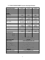
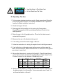
OWNERS
MANUAL
MEDIUM CONCRETE SAWS
MODELS:
C13SPM
C13SPE
C20SPE
FORM C20SP 3-2005
WARRANTY
Norton warrants all products manufactured by it against defects in
workmanship or materials for a period of one (1) year from the date of
shipment to the customer.
The responsibility of Norton under this warranty is limited to
replacement or repair of defective parts at Norton's Gainesville,
Georgia factory, or at a point designated by it, of such part as shall
appear to us upon inspection at such point, to have been defective in
material or workmanship, with expense for transportation borne by
the customer.
In no event shall Norton be liable for consequential or incidental
damages arising out of the failure of any product to operate properly.
Integral units such as gasoline engines, electric motors, batteries,
tires, transmissions, etc., are excluded from this warranty and are
subject to the prime manufacturer's warranty.
This warranty is in lieu of all other warranties, expressed or implied,
and all such other warranties are hereby disclaimed.
Important: Before placing equipment in operation, record the following
information.
MODEL:_________ SERIAL NO.___________
PURCHASE FROM: _____________________
ADDRESS: ____________________________
CITY_______ STATE ______ ZIP ________
TELEPHONE NO. ______________________
Before using this equipment, make sure that person using it
read and understand the instructions in this owners manual.
Table Of Contents
2
CONTENTS
PAGE
I. Preparation
A. Safety Precautions
B. Assembly
C. Engine Specifications
D. Pointer Alignment
4-6
7
8
9
II. Operation
A. Blade Installation
B. Starting The Engine
C. Water Supply
D. Operating The Saw
E. Cutting Technique
F. Lead-Off Adjustment
9
10
10-11
11-12
12-13
13
III. Maintenance
A. Engine
B. Bearings
C. V-Belts
D. Depth Control
E. Transmission
F. Self-Propelling Unit
G. Changing The Blade Cutting Side
14-15
16
17
18
18
19
19-20
IV. Parts List Section
A. Ordering Information
Assembly Drawing
B. Service Parts
C. Engine Warrany
21
22-2425-27
28
Read Owners Manual Before Use
Safety Alert Symbol: Information Following This Symbol Is Very
Important.
3
I. PREPARATION
A. Safety Precautions
Important! The following safety precautions must always be observed.
Hazard Symbols
Fuel (gasoline) is extremely flammable and its vapors can explode
if ignited. Store gasoline only in approved containers, in well
ventilated , unoccupied areas approved, and away from sparks or
flames. Don not fill the saw fuel tank while the engine is hot or
running. Do not start the engine near spilled fuel. Never use the
fuel as a cleaning agent
Engine components can get extremely hot from operation. To
prevent burns, do not touch the engine are or related parts while
the engine is running or immediately after it is turned off. Never
operate the engine with any heat shields or guards removed.
Keep all guard in place when operating any piece of equipment
Keep hands, feet, hair, and clothing away from all rotating parts
Lethal Exhaust Gas use only in well ventilated areas. Engine
exhaust gases contain poisonous carbon monoxide which is
orderless, colorless, and can cause death if inhaled. Avoid
inhaling exhaust fumes, and never run the engine in a closed
building or confined area
Never tamper with the governor components of settings to
increase the maximum speed. Severe personal injury and damage
to the engine or equipment or equipment can result if operated at
speed above maximum. Always obey the maximum speed rating
of blade.
DO NOT LIFT THE SAW BY THE HANDLE BARS
4
Dust and Silica Warning
Grinding/cutting/drilling of masonry, concrete, metal and other materials can
generate dust, mists and fumes containing chemicals known to cause serious or
fatal injury or illness, such as respiratory disease, cancer, birth defects or other
reproductive harm. If you are unfamiliar with the risks associated with the
particular process and/or material being cut or the composition of the tool being
used, review the material safety data sheet and/or consult your employer, the
material manufacturer/supplier, governmental agencies such as OSHA and
NIOSH and other sources on hazardous materials and make certain to comply
with all product warnings and instructions for the safe and effective use of the
material being cut. California and some other authorities, for instance, have
published lists of substances known to cause cancer, reproductive toxicity, or
other harmful effects.
Control dust, mist and fumes at the source where possible. In this regard use
good work practices and follow the recommendations of the
manufacturer/supplier, OSHA/NIOSH, and occupational and trade associations.
Water should be used for dust suppression when wet cutting is feasible. When
the hazards from inhalation of dust, mists and fumes cannot be eliminated
through engineering controls such as either vacuum and/or water mist, the
operator and any bystanders should always wear a respirator approved by
NIOSH/MSHA for the material being cut.
Use Approved:
Eye Protection
Hearing
Protection
Respiratory
Protection
5
Head Protection
1. Before mounting any blade on the saw, the blade should be inspected for
any damage which might have occurred during shipment, handling or
previous use.
2. The blade collars and arbors should be cleaned and examined for
damage before mounting the blade.
3. The blade must be properly fitted over the arbor with the drive pin on the
outside collar projecting through the drive pin hole on the blade and
inside collar.
4. The blade shaft nut, which is a left hand thread nut, must be tightened
securely against the outside blade shaft collar.
5. The blade must be operated within the specified maximum operating
speed listed on the blade.
6. Turn water control valve to full to provide adequate coolant (5 to 8
gallons per minute) for diamond blades and wet cutting abrasive blades.
Insufficient coolant could result in severe blade breakage or diamond
segment separation.
7. The blade guard must be in place with the nose guard down and locked
when the saw is running.
8. The operator should wear safety glasses and any other appropriate
safety equipment.
9. When starting the saw, the operator should stand away and to the side of
the blade.
10. If for any reason the saw should stall in the cut, raise the blade out of
the cut. Check the outside blade shaft collar and nut for tightness.
Inspect the blade for damage before restarting the saw. User caution
when resuming a cut. Be certain that the blade is in alignment with the
previous cut.
11. During cutting operations, do not exert excess side pressure on the
handles as a method of steering. Do not force the blade into the cut by
lowering the blade too fast or by pushing the saw too fast.
You Are Responsible For Your Safety!!!
6
I. PREPARATION
B. Assembly
The self-propelled concrete saws are shipped completely assembled and
ready for use except for diamond blade, gasoline, oil, and handle bar. Inspect
the saw for shipping damage. If any damage is found, contact the shipper
immediately and file a freight claim. The Norton Company is not responsible
for any freight-related damages. Remove the saw from the pallet. Reverse
the position of the handlebars so that the handle bar sticks out towards the
operator. Adjust the handlebars to the desired height. Attach the handlebars
to the saw with the supplied hardware. For electric start models fill and check
the electrolyte level and charge the battery. Read and understand the
remaining sections of this Owners Manual. NOTE: Do not install the blade
until it is time to use the saw. ANSI regulations prohibit the transportation of
any concrete saw with the blade installed.
7
C. C13SP/C13SPE/C20SPE Concrete Saw Specifications
Dimensions/Weight
Length (Transport)
Width
Height
Weights
Engine
Engine Mfg.
Model
Spec No.
Engine Type
Horse Power
Max Torque
Cooling System
Oil Capacity
Fuel Capacity
Fuel Type
Low Oil Sensor
Air Filtration
Characteristics
Max Blade
Depth of Cut 24” (406 mm)
20” (356 mm)
16” (305 mm)
Arbor Bore
Blade Shaft Locking Device
Blade Shaft Speed
Depth Control
Depth Lock
Depth Gauge
Number Of V-Belts
Blade Guard Type
Right or Left Side Cutting
Lifting Bale
Handle Bars
Water Tank
Water Tank Capacity
Water Hose Connector
Recessed Rear Wheels
C13SPM
C13SPE
C20SPE
56 inch (1142 mm)
56 inch (1142 mm)
56 inch (1142 mm)
26 inch (600 mm)
26 inch (600 mm)
26 inch (600 mm)
40 inch (1016 mm)
40 inch (1016 mm)
40 inch (1016 mm)
385 lbs (175 kg)
405 lbs (175 kg)
428 lbs (195 kg)
Honda
Honda
Honda
GX390
GX390
GX620
GX390K1QXC9
GX390K1QAE2
GX620K1QXW2
Single Cylinder
4 Cycle
13 hp (9.5kW)
@ 3,600 rpm
19.5 ft-lbs (26.5
Nm, 2.7 kgf-m)
@ 2,500 rpm
Air
Single Cylinder
4 Cycle
13 hp (9.5kW)
@ 3,600 rpm
19.5 ft-lbs (26.5
Nm, 2.7 kgf-m)
@ 2,500 rpm
Air
1.1 liter
(1.16 US qt)
6.5 liter
(1.79 US gal)
Unleaded Gasoline
(86 pump octane)
Yes
1.1 liter
(1.16 US qt)
6.5 liter
(1.79 US gal)
Unleaded Gasoline
(86 pump octane)
Yes
Four Stage
Cyclone
20” (356 mm)
Two Stage
Honda
Two Cylinders
4 Cycle
20 hp (14.9kW)
@ 3,600 rpm
32.5 ft-lbs (44.13
Nm, 4.50 kgf-m)
@ 2,500 rpm
Air
1.8 liter
(1.90 US qt)
9 liter
(2.48 us gal)
Unleaded Gasoline
(86 pump octane)
Yes
Four Stage
Honda
20” (356 mm)
24” (406 mm)
-NA-
-NA-
9-1/2 inch (241 mm)
7-1/2 inch (191 mm)
7-1/2 inch (191 mm)
7-1/2 inch (191 mm)
5.50” (140 mm)
5.50” (140 mm)
5.50” (140 mm)
1 inch (25.4 mm)
Machined Into Flats Of Tight Collar
2600 rpm,
Hand Wheel With Screw Feed
Standard
Customer Installed Accessory
4
Hinged, All Steel Construction
Yes
Built In
Adjustable, Stays Level At All Times
Standard
5.28 US Gallons (20 liter)
Standard Garden Hose With Flow Control Valve
Standard
8
II. OPERATION
Read and understand this manual before
running or using the machine!
A. Installing the Blade
1. Disconnect the spark plug and then insert the Blade Shaft Locking Pin
into the Blade Shaft Locking hole.
2. Remove the blade shaft nut, (Turn clockwise) , and remove the outside
collar.
3. Clean off any foreign particles on the clamping surfaces of both collars
and on the mounting surface of the blade.
4. Place the blade on the blade shaft, lining up the drive pin hole in the
blade with the drive pinhole in the inside collar.
Use only Clipper Diamond Blades. This machine was not
designed for the use with abrasive blades.
5. Slide the outside blade shaft collar onto the blade shaft . The drive pin
on the outside collar must project through the drive pin hole in the
blade and into the inside collar.
6. Tighten the blade shaft nut (counter-clockwise) securely against the
outside collar and remove the Blade Shaft Locking Pin.
7. Reconnect the spark plug.
Blades Use Only Clipper Diamond Blades
9
B. Engine
Prior to attempting to operate the engine, read the information
contained in the engine owner's manual. An engine owners manual is
supplied with every gasoline powered concrete saw.
1. Check Oil: Add oil if low. Refer to the engine owner's manual for the
recommended SAE viscosity grades. Capacity of oil is 1.1 liters (1.16 US qt)
2. Check Fuel: Fill if low. Use only unleaded gasoline with a pump sticker
octane rating of 86 or higher is recommended. Never use an oil and
gasoline mixture!
3. Air Cleaner: Never run the engine without the air cleaner! Rapid engine
wear will result from contaminants being drawn through the carburetor and
into the engine.
4. Engine Starting: Refer to the engine owner's manual for proper engine
starting procedure.
5. Engine Speed: Always run the engine and the proper speed for the blade
being used. Never run the blade at a higher speed that it is rated for. See
the Blade Speed chart located on the machine’s console or located in the
manual under the heading “Operating the Saw”
C. Water Supply
Pressurized source: Turn the water control to full "ON" when using wet
cutting blades. The required flow rate is 4-6 gallons per minute.
Water Tank on saw: This supply is designed for use with dry blades to
keep the dust levels down. The tank will not supply the proper water flow
rates when used with wet cut only blades. Do not drink the water from this
tank. Fill the tank with water only. Close the water tank valve. Attach the
saws water supply hose to the tank outlet. Fill the tank with water. The
capacity of the tank is 5 US Gallons. When you are ready to cut, adjust
the water supply rate until a fine mist or a slow trickle is made. The
use of water greatly decreases the amount of dust produced during the
cutting process, aids in the cooling of the blade, and provides additional
stability.
10
•
•
Use Only Water In The Water Tank
Do Not Drink From The Tank
D. Operating The Saw
1. For the engine starting instructions see the Engine manual and follow the
instructions located in section A. Installing the Blade of the II. Operation
heading for Blade installation instructions.
2. Check the Engine Oil level.
3. Disengage the Self-propelling unit by moving the Transmission
Engage/Disengage lever fully up and place the Speed Control in the
neutral position.
4. Raise the saw to the full upright position. Do not let the blade come in
contact with the ground.
5. Maneuver the saw to the desired starting point.
6. If wet cutting connect the water supply to the saw.
7. Follow the instructions for starting the engine found in the Engine manual.
8. If wet cutting turn on the water supply at the source and then open the
water valves on the saw. Make sure that there is a minimum of two gallons
per minute of water flow!!
9. Be sure that the engine is running at full throttle!!! Check Engine Speed
on the Tachometer to that listed on the Blade Speed Chart located on the
Console is correct for the diameter of Blade being used.
Blade Eng RPM Eng Pulley
16
20
24
3600
3600
3000
2.65
2.65
2.65
B/S RPM
2600
2600
2200
B/S
Pulley
3.65
3.65
3.65
10. Slowly lower the blade by rotating the hand wheel counter-clockwise until
the desired depth of cut is reached. Use a reasonable rate of feed. Do
not force the blade in to the cut!!
11
11. For Self-propelled models move the Transmission Engage/Disengage
lever by fully to the Engage position and \ then slowly push the Speed
Control forward until the desired speed is reached. If the engine begins
to stall or the saw raises out of the cut slow the forward speed down!!
The further the lever is pushed the fast the saw will move.
12. When the end of the cut is reached, slowly raise the blade out of the cut
by rotating the Hand Wheel Clockwise until the blade is at least one (1)
inch above the ground.
13. To use reverse, move the saw move the Speed Control lever to the rear
of the saw. Only move the saw in reverse with the blade in the raise
position. Always place the speed control back in the neutral position after
moving the saw.
14. When moving the saw to a new location be sure that the blade is not
touching the ground and always pay close attention to where you are
moving and where the blade is at all times.
15. To disengage the transmission, place the Speed Control in the Neutral
position and then slide the Transmission Engage/Disengage lever by fully
to the “Disengage” position.
Caution: Do Not Engage Or Disengage The
Transmission While The Machine Is In The
Forward Or Reverse Positions!
E. Cutting Technique
Lower the blade into the concrete to the required depth by turning the hand
wheel counter-clockwise. Ease the handle slowly forward . Retard the
forward pressure if the saw begins to stall.
Note: For deeper cuts (4 inches or more), several cuts should be made in
incremental steps of 1-1/2 to 2 inches until the desired depth of cut is
reached.
Push the saw steadily forward using the front pointer as a guide. Exert
enough forward pressure so that the engine begins to labor, but does not
slow down. If the saw begins to stall, retard the forward movement until full
rpm is restored to the blade. If the saw stalls, raise the blade out of the cut
before restarting. Avoid excessive side pressure or twisting of the blade in
the cut.
12
Additional Guide Lines For Sawing:
•
Understand and follow all of the instruction in this owners manual.
•
If wet cutting, turn on the water supply so that there is a minimum of two
gallons per minute of water flow!!
•
In critically hard aggregate more than a single pass may be needed to cut
the desired depth.
•
Only move the Engage/Disengage lever while the transmission speed
control is in the neutral position.
•
Move the transmission speed control slowly.
•
If the saw stalls in the cut, immediately stop the forward speed and raise
the blade out of the cut. If this is not done the belts can fail or the blade
may be damaged.
•
Go slowly with a new blade until it opens up, that is, until the diamonds
can be seen and felt.
•
If the saw leads off excessively check the contact between the drive rollers
and the rear wheels. Small steering corrections may be made by applying
slight pressure to the right or left side of the handle bar. The drive rollers
will need to be cleaned from time to time.
F. Lead-Off Adjustment
If the saw tends to lead off (cut to one side), it may be steered by applying
slight pressure to the left or right hand handles.
13
A. Engine
Follow the below schedule for engine maintenance. NOTE: Check the Honda
Engine manual that came with the engine for any changes to the
maintenance schedule. If the charts have any differences, follow the chart in
the Honda Engine Manual.
The Norton Company does not warranty the engine. If any warranty or
service of the engine is required contact your nearest Honda service center,
or from the Internet: http://www.honda-engines.com/home.htm
Honda Power Equipment Group
4900 Marconi Dr.
Alpharetta, GA 30005-8847
Tel: (800) 426-7701 | Fax: (678) 339-2670
Honda engine (refer to owner's manual for complete maintenance.)
Check the engine oil level before each use when the engine is cool and the
engine is level. Add oil if the level is low. The oil level should be within the
operating range (see the engine owner’s manual for details).
Only use a high-detergent, premium quality motor oil certified to meet or
exceed U.S. automobile manufacturer’s requirements for Service
Classification SG, SF/CC, CD. Motor oils will show the classification on the
container. A SAE viscosity of 10W-30 is recommend by Honda for general,
all temperature use. Please consult the below chart or contact your local
Honda service center for the proper viscosity for your temperature range.
14
Always refer to the engine manual for more detailed information on checking
the oil, changing oil, and oil capacity, air filter changes, and fuel type to use.
Use only Honda air filters. Do not clean the air filter with gasoline or other
flammable solvents. A fire or explosion could result. To clean, follow the
instructions found in the Honda engine manual.
Dry Cutting Engine Maintenance
9 When operating the engine in dry cutting or dusty environments the following
is required:
9 Engine oil changed more often.
9 Every 50 hours (or more often if conditions require) clean all of the engine
cooling fins.
9 Every 25 hours (or more often if conditions require) clean the engine
precleaner.
9 Every 100 hours (or more often if conditions require) replace the air filter. If
the engine is equipped with a reusable air cleaner, clean and re-oil it.
9 Check and clean the air filter after each use. Replace as needed.
15
B. Bearings
Re lubrication type bearings must be relubricated daily to assure long life.
The grease used should conform to the NLGI grade two consistency and
be free of any chemical impurities such as free acid or free alkali, dust
rust, metal particles or abrasives.
For best results, bearings should be relubricated while in operation. Note:
Due caution for personal safety must be observed when servicing
rotating equipment. The grease should be pumped in slowly until a
slight bead forms around the seals. This bead, in addition to acting as an
indicator of adequate relubrication, provides additional protection against
the entry of foreign matter. If necessary to relubricate while the bearing is
idle refer to relubrication table for maximum grease capacity for the
various size bearings.
Shaft Size
Maximum Grease Capacity of
Bearing Chamber in Ounces
1/8
3/8
5/8
1/2"' to 3/4"
7/8" to 1-3/16"
1-1/4" to 1-1/2"
16
III. MAINTENANCE
C. V-Belts
Warning: Never make adjustments to belts or pulleys while
engine is running!
1. The best tension for a belt drive is the lowest tension at
which the belts will not slip under full load.
2. Simply take up the drive until the belts are snug in the
grooves. Run the drive for about 15 minutes to "seat" the
belts. Then impose the peak load. If the belts slip tighten
them until they no longer slip at peak load.
3. Remember too much tension shortens belt and FIGURE 1
bearing life!
FIGURE 2
4. Check the belt tension frequently during the first day of operation. Check
the belt tension periodically thereafter and make any necessary
adjustments.
5. The two most common causes of misalignment are shown in the drawing.
a). The engine drive shaft and the blade shaft are not parallel.
FIGURE ONE
b). The pulleys are not located properly on the shafts.
FIGURE TWO
6. To check alignment , all you need is a steel straight edge .
7. Line up the straight edge along the outside face of both pulleys as shown
in the drawing.
8. Misalignment will show up as a gap between the pulley face and the
straight edge.
9. Make sure that the width of the outside land is equal on both pulleys.
17
III. MAINTENANCE
D. Depth Control
The depth control (raising screw) consists of a threaded rod which feeds into
a brass nut . In order to keep the two parts working smoothly it is necessary
to keep the rod free from dirt and sludge as much as possible. Cleaning the
threaded rod with a rag after each use will prevent sludge from collecting in
the tube assembly and protect the threads. It is a good practice to keep the
raising screw threads lubricated, as the slurry generated during cutting will
cause premature thread wear.
The bearing used to support the raising screw should be checked after each
use to make sure it is turning freely and lubricated. If the bearing requires re
lubrication a lithium base grease is recommended.
E. Transmission
Eaton Model 6 Hydrostatic Transmission:
1. Accurate fluid level readings can only be made when the fluid is cold.
2. If the natural color of the fluid has become black or milky, the transmission
has over heated or water containment has occurred. Drain and replace the
fluid, check the fan and accessory belts, clean the cooling fins, and also
check for any fluid leakage. Do not pressure wash the transmission.
3. Use only the proper viscosity and type of fluid. At normal operating
temperatures, the optimum viscosity range is between 80-180 SUS (16-40
CS) and it should never fall below 60 SUS (10 CS).
4. The fluid should be chemically stable, incorporating rust and oxidation
inhibitors.
Recommended Fluids For Eaton Model 6 Transmissions
1.
Mobil Fluid 300
2.
Texaco TL 2209
3.
Dextron B (General Motors)
4.
M2C-33F And M2B-41A (Ford Motor)
5.
Hy-Tran (International Harvester)
6.
10W Straight Viscosity SE, CC, or CD Rated Engine Oil
* 7. 20W Straight Viscosity SE, CC, or CD Rated Engine Oil
8.
30W Straight Viscosity SE, CC, or CD Rated Engine Oil
* Factory Supplied Transmission Fluid
18
F. Self-Propelling Operations
1. Speed Control Lever:
The operators right hand lever is the speed control lever. Pushing the
lever slowly forward will increase the forward speed of the saw. Pulling it
to the center will place the saw in neutral. Pulling the saw to the rear of
the console (from the neutral) will increase the reverse speed.
2. Transmission Engage/Disengage Lever:
Transmission Engage/Disengage lever has two (2) positions onto which it
can be moved: Engaged position (Down) allows the transmission to
operate the rear drive wheels by the means of rear wheel friction rollers,
the Disengage position (Up) release the rear wheel friction rollers from the
rear drive wheel (the saw can be “Free Wheeled” or moved when
repositioning the saw or moving it without running the engine. NOTE:
When parking the saw, it should always be left in the Engaged
position , Speed Control Lever in the neutral position, the engine
OFF, and perpendicular (right angle) to the grade (hill).
3. Drive Wheel Adjustment:
Keep the chain clean and properly adjusted. To change the engagement
pressure of the friction rollers, disengage the transmission and reposition
loosen the fasteners that mount this lever to the transmission and readjust
the friction rollers so that there is a 1/4” clearance (move the transmission
platform up or down) between the friction rollers and the rear wheels.
Retighten the mounting hardware.
Clean the rear friction rollers wheels, slurry will build up on the friction
rollers and cause the friction rollers to slip. Normally spraying the friction
rollers and rear wheels with water will clean out the slurry.
G. Changing The Blade Cutting Slide
The saws can be used for either left or right hand cutting. Tight and loose
collars fit both the left and right ends of the blade shaft.
To Change Blade Guard Side Follow The Below Directions: NOTE: The
following directions are based on the blade guard being mounted on the
operators Right hand saw. The blade shaft nut on the operators Right hand
side is a Left handed threaded and the blade shaft nut on the operators Left
hand side is a Right handed thread. Reverse the following directions to move
the blade guard from the operators Left hand side to the Right.
1. Disconnect number one spark plug on the engine.
19
2. Remove the operators Right hand side blade nut (NOTE: Left hand
thread) and Loose Collar.
2. Remove the blade from the saw if installed.
3. Remove the Blade Guard buy loosing the Blade Guard Locking Screw
located on the front side of the Blade Guard and remove the Blade Pivot
Bolt, Washer, and Nut from the rear of the Blade Guard.
4. Remove the Blade Shaft Guard from the operators left hand side of the
machine.
5. Swap the sides of the Blade Guard Locking Screw (now should be on the
Right side of the guard).
6. Reroute the Water Hose around to the Left side of the machine. NOTE:
Do not let the Water Hose come in contact with the Muffler or the Engine.
7. Attach the Blade Guard to the operator’s Left hand side of the machine.
NOTE: The head of the Blade Pivot Bolt goes to the inside of the frame.
The Nut goes to the outside of the blade guard. Tight down the Blade
Guard Locking Screw.
8. Remove the Operator’s Left hand side Blade Nut and Loose Collar.
9. Place the Blade on the Operator’s Left hand side of the Blade Shaft.
10. Attach the Loose Collar and Operators Left hand side Blade Shaft Nut to
the machine. Properly tighten the Blade Shaft Nut.
11. Attach the Operator’s Right hand side Loose Collar and Blade Shaft Nut.
12. Attach the Blade Shaft Guard to the Operator’s Right hand side of the
machine.
13. Remove the Pointer and reattach it to the Operators Left hand side of the
machine. NOTE: Reverse the orientation of the Pointer.
14. Retighten all Screws.
15. Reattach the Spark Plug Wire.
20
IV. PARTS LIST SECTION
A. Ordering Information
1. List model number and serial number of machine.
2. List part number and serial number of part not the item number.
3. Wherever alternate parts are shown due to product improvement, inspect
the part you have and provide additional description as necessary.
4. Specify mode of shipping desired, such as, parcel post, truck, U.P.S., best
way, etc.
For the nearest Clipper distributor call 1-800-554-8003
Common Replacement Parts
Description
Belts V-belts (set of 4)
Blade Shaft Nut ¾-16 Left Hand Thread
(Operators Right Side Of Saw)
Blade Shaft Nut ¾-16 Right Hand Thread
(Operators Left Side Of Saw)
Collar Tight (Operators Right Side)
Collar Tight (Operators Left Side)
Collar Loose Assembly (With Pin)
Drive Pin ∅3/8 x 1
Bearing Blade Shaft (1)
Front Wheel Complete (1)
Rear Wheel (1)
Wrench 1-1/2”
Wrench 32mm
Wrench 17mm
Part Number
227156
227191
227159
227190
227247
227154
105377
82910
72279
NOTE: All Parts Are Sold As Individual (each) Unless Noted Otherwise
Blades Use Only Clipper Diamond Blades. Contact your local Clipper
Distributor or Clipper at 1-800-554-8003 for the best blade for the application.
21
B: Service Parts
C13SP & C20SP Common
C13SP
C20SPE
Item
1
2
3
4
5
6
7
8
9
10
11
12
13
14
15
16
17
18
19
20
21
22
23
24
25
26
27
28
29
30
31
32
33
34
35
36
37
38
39
40
41
42
43
44
45
46
47
Model
All
All
All
All
All
All
All
All
All
All
All
All
All
All
All
All
All
All
All
All
All
All
All
All
All
All
All
All
All
All
All
All
All
All
All
All
All
All
All
All
All
All
All
All
All
All
All
All
All
Part No
83925
83926
83927
83928
83929
83930
83931
83932
83933
72097
83934
83935
83936
84045
84032
83357
82794
72357
227116
107859
83218
72286
82998
83937
83938
83939
84033
83367
84034
83940
82786
84036
84046
84047
84035
83941
84066
72067
83942
76670
76357
76465
84048
83943
84049
83944
84050
75061
83947
UPC #
70184674388
70184650630
70184682454
70184648715
70184681299
70184681064
70184681040
70184655787
70184655903
70184681046
70184665218
Description
Upper Frame
Board plate
Upper closing plate
Under closing plate
Pivoting frame
Belt guard
Transport handle
Handle support
Depth indicator
rubber handle
Lifting hook
Water tank support
Guide-a-cut
Wheel guide-a-cut
Pointer
Water tank
Water tank stopper
Tap
Fit 1/2MPT X3/4 F Garden Hose SW
Valve Ball 1/2" Brass
Water connector
Water connector Y
Nozzle (set of 2)
Blade guard 16"
Blade guard 20"
Blade guard 24"
Splash guard
Fixing screw
Cover for collar
Rocking frame
Front wheel
Hiding part
Back wheel
Wear ring
Bearing
Tube raising nut
Stop ring
Stop ring
Raising screw
Bearing + screws
Handwheel
Handwheel handle
Fixing ring
Handle stay level bar
Fixing ring
Handle stay level shaft
Wear ring
Bearing
Screws
48
49
50
51
52
53
54
55
56
57
58
59
60
61
62
63
64
65
66
67
68
69
70
71
72
73
74
75
76
77
78
79
80
81
82
83
84
85
86
87
88
89
90
91
All
All
All
All
All
All
All
All
All
All
All
All
All
All
All
All
All
All
All
All
All
All
All
All
All
All
All
All
All
All
All
All
All
All
16”
20”
24”
All
All
All
All
All
All
All
All
All
C13SP
M
C13SPE
C20SP
All
83945
83946
72279
70807
82910
83314
83948
227159
83949
72474
83950
83951
83952
227190
227247
83361
83359
83953
83954
83955
83956
83957
84037
73860
83958
84038
84039
76670
83959
84040
84041
83960
84053
84051
82808
84052
72345
84042
84043
83961
83962
83963
83964
83965
83967
83968
83370
84044
82811
83966
70184655806
70184655735
70184681049
70184681050
70184673904
70184681598
70184674352
70184674082
70184681056
70184681055
70184655903
Depth lock wheel
Shaft
Wrench 17mm
Wrench 19mm
Wrench 32mm
Wrench 1 1/2"
Blade shaft complete
Inside collar
Blade shaft alone
Bearing & screws
Pulley & key (16" blade)
Pulley & key (20" blade)
Pulley & key (24" blade)
Inside collar
Outside collar
Nut RH Thread
Nut LH Thread
Belt tensioner cpl.
Tension disc
Tension spring
Tension arm
Motor pulley
Pulley transmission
Hydrostatic transmission
Bracket speed adjustment
Fixing bracket
Friction disc
Bearing Flange Kit Depth Control
Advance shaft
Bevel gear
Bevel gear
Hydrostatic trans. Support
Chain
Belt
Belts XPZ 860 LW (set of 4)
Belts XPZ 900 LW (set of 4)
Belts XPZ 910 LW (set of 4)
Spring
Advance bar
Speed lever
Lever
Throttle
Throttle
Battery support
Battery protection part
Motor support
Motor GX390 Manual start
Motor GX390 Electric start
Motor GX620 Electric start
Battery YBP16-B
92
93
All
All
84067
73862
Waste oil hose
Fan
NOTES
Norton Construction Products
PO Box 2898
Gainesville, GA 30503
Phone: 800-554-8003 or 770-967-3954
(8:00 A.M. to 7:00 P.M. Eastern Time)
Fax: 800-443-1092 or 770-967-7287