1
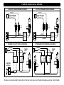
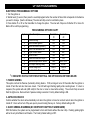
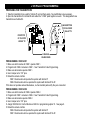
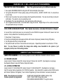
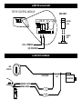
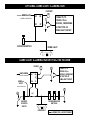
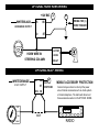
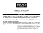
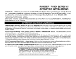
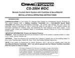
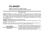
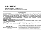
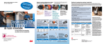
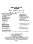
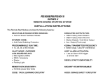
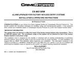
CS-2007DC / WDC
REMOTE CONTROL ALARM SYSTEM
INSTALLATION HANDBOOK
INTRODUCTION
This booklet is written and designed for professional installation technicians who have been trained in
automotive electrical testing, trouble-shooting, and installation.
*IMPORTANT INFORMATION: Primary and Optional Features
-PRIMARY: These are features that must be connected in order for the system to operate properly i.e. Siren,
L.E.D., Power, Ground, Doorpin, etc.
-OPTIONAL: These are features to be connected only if desired or agreed upon by the installing dealer (i.e.
Door Locks, Flashing Lights, Starter Disable, Hood, Trunk, and Auxiliary Remote Outputs etc.)
TECH SUPPORT
Mon-Fri 8:00 AM-4:30 PM Pacific Time
(800) 998-6880
website: www.crimestopper.com
email: [email protected]
This device complies with FCC Rules part 15. Operation is subject to the following
two conditions: 1) This device may not cause interference, and (2) this device
must accept any interference that may be received, including interference that may
cause undesired operation. The manufacturer is not responsible for any radio or
TV interference caused by unauthorized modification to this equipment. Such
modification could void the user's authority to operate the equipment.
INSTALLATION CAUTIONS & WARNINGS
BEFORE BEGINNING, check all vehicle manufacturer cautions and warnings regarding electrical service (AIR
BAGS, ABS BRAKES, AND BATTERY).
TO PREVENT A POSSIBLE DEAD BATTERY remove vehicle dome light fuse while working on the vehicle.
MAKE CERTAIN TO REINSTALL FUSE PRIOR TO TESTING FOR DOOR TRIGGERS.
DO NOT EXCEED MAXIMUM OUTPUT RATINGS! - SERIOUS DAMAGE MAY OCCUR. LIMITS FOR
ALARM FUNCTIONS ARE LISTED WHERE APPLICABLE. IF UNSURE ABOUT CURRENT LOAD,
MEASURE LOAD WITH AN AMP-METER.
REMOVE MAIN SYSTEM FUSE(S) before jump starting the vehicle or charging the battery at high boost.
DAMAGE MAY OCCUR TO SYSTEM IF PROPER PRECAUTIONS ARE NOT OBSERVED.
DO NOT ROUTE ANY WIRING THAT MAY BECOME ENTANGLED with brake, and gas pedals, steering
column, or any other moving parts in the vehicle.
CONTROL MODULE MOUNTING
DO NOT Mount the control unit in the engine compartment.
DO NOT Mount the control unit or wiring harness where they can become entangled with moving parts
such as brake/gas/clutch pedals, or the steering column.
The alarm control module should be mounted in a concealed location. The Placement of the module will
affect the distance from which the remote transmitter can control the unit. The antenna wire should be routed
away from any metal if possible. Do not alter the length of the antenna wire or route it with other wires. Do
not ground the antenna wire.
Underdash Mounting: If you are locating the control unit underdash, mount it as high as possible not easily
located by an intruder.
Driver’s Side underdash mounting provides an easy location for wiring however this is a common location for
an intruder to check for an alarm after breaking into the vehicle. The left side of the vehicle may contain more
metal and or wiring that will create interference and decrease the operating range of the system.
Passenger Side underdash is often the best location, however some extra wiring may be needed to extend
wires across from the driver’s side.
Under-seat / Center Console mounting is also a possibility however range be affected by metal structures
and of the unit may be exposed to moisture from spilled drinks etc. Moisture or Damage caused by corrosion
is not covered under warranty.
COMPONENT MOUNTING
SIREN MOUNTING: Mount the siren under the hood to fender-well or other body surface with the open end facing
downward. Run the red siren wire through the firewall using a rubber grommet. Ground the black wire to the body
metal near the siren.
LED: Mount the red LED in a visible location on the dashboard or console. Drill an 11/32" hole at the chosen location.
Shock Sensor: Mount the included shock sensor with wire ties to an under dash wire harness or fasten with screws to
firewall or side paneling.
Override/Program Button: Mount the Override/Program push-button in a hidden location easily accessible to the
user in case the system must be disarmed without the use of the transmitter. This switch is also used to program
certain features.
WIRING
MAIN HARNESS: 10 PIN 18 GA. WIRES
WHITE WIRE: +12V FLASHING PARKING LIGHT OUTPUT (Optional)
Connect to switched parking light wire at back of light switch. If this is not possible, connect directly to one of the
parking lights at the front of the vehicle. European vehicles require separate right and left circuits. Use a dual relay or
2 diodes to separate the output signal.
RED WIRE: +12V POWER INPUT (15 amp fuse)
Connect to +12 Volt source with supplied fuse & holder. Recommended location for this connection is at the vehicle
battery positive terminal.
BROWN WIRE: (+) SIREN OUTPUT (2 Amp Max.)
Connect to RED siren wire.
BLACK WIRE: SYSTEM CHASSIS GROUND
THIS WIRE MUST BE CONNECTED TO CHASSIS METAL OF THE VEHICLE. Scrape away any paint or dirt from
the connection point to ensure a good connection. We recommend the kick panel area for your ground point.
ORANGE WIRE: STARTER KILL / NEGATIVE ARMED OUTPUT (500mA Ground)
Ground output when system is armed. This output is used for disabling the starter or to activate other devices such as
scanner LED’s, window modules, voice modules etc. For starter kill, cut starter wire and connect between 87A and 30
on relay. Connect orange wire to 85 and connect 86 to an Ignition source that has voltage in the ON and CRANKING
position.
CARJACK OUTPUT: When the system is programmed for Carjack operation, this output also turns on 8 seconds after
the siren trigger for activation an additional sounding/signaling device. Use with a relay triggered only by Ignition ON!
3
WIRING
GRAY WIRE: (-) AUX REMOTE OUTPUT 1 (Optional, requires relay)
Connects to terminal 85 of a relay. Connect terminal 86 to constant. Connect terminal 87 to +12V constant or ground
depending on the type of circuit that needs to activated. Connect terminal 30 to the device/circuit to be activated.
GREEN WIRE: (-) DOOR TRIGGER
Identify the wire that reads ground when any door is open and 12 volts when all doors are closed. Some vehicles may
have isolated door triggers. In this case you may need to run additional wires from other doors or go directly to the
wire that triggers the vehicle’s dome light.
BLUE WIRE: (-) HOOD/TRUNK TRIGGER
This wire is an input trigger for a grounding hood or trunk pin switch. Connect to existing hood and trunk pin switches
that read ground when open. If no existing switches are available, install new pin switches. Note: DO NOT mount new
pin switches in water pathways.
VIOLET WIRE: (+) DOOR TRIGGER
Same as GREEN wire above except this wire is used for vehicles that show a positive voltage (12 volts) when the door
is open such as Ford.
YELLOW WIRE: IGNITION SWITCHED “ON” AND “START” +12 VOLTS
Connect to an ignition wire (or fuse in the fuse box) that shows +12 Volts when the key in both “On” and “Start”
positions.
4 PIN PLUG: (-) OPTIONAL FEATURES / ACCESSORY WIRING
WHITE WIRE: PARKING LIGHT OUTPUT #2 (Optional, European Vehicles)
This wire is used on European vehicles that require left and right isolated parking light output circuits. Connect this
wire to the 2nd half of the circuit from where the other WHITE wire (Main Harness) is located.
WHITE/ORANGE WIRE: REMOTE OUTPUT 2 or MOBILE ACC. PROTECTION (Optional, Requires Relay)
This wire is programmable to operate in two different ways: 1. Remote Auxiliary Output 2 providing a (-) Negative
Momentary Output with a Double-Press of Button 2 on the remote control. 2. M.A.P. providing a continuous (-)
Negative output when in VALET PARK MODE. Interrupt power/accessory wiring to prevent unauthorized access of
the vehicle’s audio or entertainment systems when Valet Park mode is ON.
WHITE/GREEN WIRE: Dome Light Illumination (Optional, Requires Relay)
Connect to terminal 85 of relay. Connect terminal 86 to constant. Connect terminal 87 to +12V constant or ground
depending on the type of dome light circuit in the vehicle. 30 to the dome light circuit.
WHITE/BLACK WIRE: (-) HORN HONK OUTPUT (Optional, requires relay)
Connects to terminal 85 of a relay. Connect terminal 86 to +12V Constant. Connect terminal 87 to +12V or ground
depending on the type of horn activation circuit in the vehicle. Connect terminal 30 to the horn activation circuit.
WIRING
BROWN 14 GAUGE (2 WIRES)
The Two 14 GA. Brown wires connect directly to the Vehicle’s STARTER wire to bypass this circuit
when the alarm system is armed or tripped (Starter Kill). Locate the “Start” Wire in the vehicle (Power
During Crank position only). Cut this wire and Connect the Each ends to A 14 GA Brown wire for the
Control Module. This is a NORMALLY CLOSED Starter Disable Circuit.
2 PIN PLUG (BLUE): PROGRAM/OVERRIDE PUSH BUTTON
2 PIN PLUG (RED): LED INDICATOR (RED FLASHING LIGHT or BLUE LED w/BLUE FURY)
4 PIN (WHITE) SENSOR PLUG:
WHITE WIRE: NEG. WARN AWAY
BLUE WIRE: NEG. TRIGGER
BLACK WIRE SENSOR GROUND
*The Sensor supplied with the system does not require
any additional wiring, simply mount the sensor in a
suitable location, plug in, and adjust sensitivity.
RED WIRE SENSOR +12V POWER
POWER DOOR LOCK WIRING
4 PIN PLUG (YELLOW) DOOR LOCKS (OPTIONAL):
GREEN: (-) Negative LOCK pulse / (+) Positive UNLOCK pulse
RED: +12V Coil Power for external relays (Term. 86).
BLUE: (-) Negative UNLOCK pulse / (+) Positive LOCK pulse
WHITE/BLUE WIRE: (-) PASSENGER (S) DOOR UNLOCK OUTPUT (Optional, requires relay)
Connects to unlock circuit for passenger door(s) when using separate driver’s door unlock option. See DOOR LOCK
WIRING for configuration options.
DETERMINING DOOR LOCK TYPE: We recommend determining the type of locking system the vehicle has
before connecting any wires. Incorrect connection will result in damage to the remote start and/or vehicle
locking system. There are several types of door lock systems in vehicles today. Below is listed the many
types of common locking systems:
Negative trigger: Most Japanese; Ford, New GM
Positive trigger: Many GM; Some Chrysler
One wire dual voltage: Newer /Chrys/Dodg/Plym; Ford Probe
Reverse Polarity: Chrys/Dodg/Plym; GM; Ford
Ground/open: Some Nissan; Subaru
Semi-automatic: Older Saab and Volvo
Electric vacuum pump: Pre-‘95 Mercedes-Benz
POWER DOOR LOCK WIRING
NEGATIVE TRIGGER DOORLOCK WIRING
POSITIVE TRIGGER DOORLOCK WIRING
GREEN
GREEN
RED
RED
BLUE
BLUE
L
IN4001
IN4001
DIODES
DIODES
FACTORY
POWER
LOCKING
RELAYS
LOCK
UL
UNLOCK
REVERSE POLARITY DOOR LOCK WIRING
L
FACTORY
POWER
LOCKING
RELAYS
LOCK
UL
UNLOCK
AFTERMARKET MOTOR/DOOR LOCK WIRING
GREEN
GREEN
FUSED
+12V
+
RED
BLUE
85
86
87
87A 30
85
86
87
87A 30
FUSED
+12V
+
RED
BLUE
85
86
87
87A 30
85
86
87
87A 30
MASTER
SWITCH
+
CUT
L
UL
CUT
Diodes are recommended for protection of the door lock outputs on Positive & Negative systems. (Not included)
SEPARATE DRIVER’S DOOR UNLOCK WIRING
WIRING FOR REVERSE POLARITY DOOR LOCKS
WHITE/BLUE
GREEN
RED
BLUE
DRIVER'S
DOOR MOTOR
FUSED
+12V
+
86
87
30 87A
85
85
86
87
87A 30
+
L
85
86
87
87A 30
L
CUT
UL
CUT
+
UL
CUT
UNLOCK WIRE
WIRING FOR POSITIVE TRIGGER DOOR LOCKS
WHITE/BLUE
GREEN
RED
BLUE
85
86
87
30
DRIVER'S
DOOR MOTOR
85
86
87
30 87A
L
L
UL
UL
+
UNLOCK WIRE
CUT
+12V
FUSED
FACTORY LOCK
RELAYS
OPTION PROGRAMMING
ELECTRONIC PROGRAMMABLE OPTIONS
1. Turn the ignition on
2. Wait at least (1) second, then press the override/program button the number of times that corresponds to the feature
you want to change. (See the list below) The siren will chirp once for each button press.
3. Press button #1 or #2 on the transmitter to change the option. The siren will chirp once for Button #1 or twice for
Button #2 to confirm programming.
PROGRAMMING OPTIONS CHART
Option #
1
2
3
4
5
6
7
8
9
10
11
Option Description
Passive Arming
Auto Lock with Ignition
Silent Arm/Disarm (Button1)
Doors Lock w/Passive Arm
Lights on with disarm
Active Re-Arm
Disarm with Remote Output 1
Remote Output 2/MAP Switch
Door Open Warning Delay
Vehicle Assignment
Double Unlock Pulse
* = INDICATES THE FACTORY PRESET SETTING.
Press Button
#1
ON*
ON*
ON
ON*
ON
ON
ON*
MAP
8 Sec.*
VEH #1*
ON
Press Button
#2
OFF
OFF
OFF*
OFF
OFF*
OFF*
OFF
Rem. Out 2*
60 Sec.
VEH #2
OFF*
SEE OPTION DESCRIPTIONS BELOW
1. PASSIVE ARMING
This option controls the Passive (Automatic) Arming feature. If ON, arming will occur 30 Seconds after the ignition is
turned off and the last door has been closed. The LED will begin flashing rapidly while counting down. If a door is
reopened, the system will wait (LED solid) for the door or zone to close before arming. The unit will chirp once and
flash the lights once. Doors will lock if passive locking is selected. Factory default setting is ON.
2. AUTOLOCK/UNLOCK
Controls whether the doors will automatically lock when the ignition is turned on and will unlock when the ignition is
turned off. Doors will not lock if they are open to prevent locking the keys in. Factory default setting is ON
3. SILENT ARMING /DISARMING (NO CHIRPS WITH BUTTON #1 ARM/DISARM)
With this feature, the system can be programmed to Arm and Disarm without the siren chirp. Flashing parking lights
will be the only Arm/Disarm confirmation. The Factory Default setting is OFF.
OPTION PROGRAMMING
OPTION DESCRIPTIONS - SEE CHART ON PAGE 8
4. DOOR LOCK WITH PASSIVE ARM
This option controls whether the doors will lock when Passive Arming occurs. Note: May increase the risk of locking
keys in the vehicle. Factory default setting is ON.
5. PARKING LIGHTS ON WITH DISARM
Keeps parking lights on instead of 2 flashes when system is disarmed to assist in locating your vehicle in a crowded
parking lot or structure. Light will stay on for 30 Sec. or until Ignition is turned on. Factory Default setting is OFF.
6. ACTIVE RE-ARMING
Active Re-arming allows the system to re-arm itself 30 seconds after disarmed with the transmitter if a door has not
been opened. This is handy if the vehicle is accidentally disarmed (via the Transmitter in your pocket) without you
knowing it. The Factory default setting is OFF.
7. DISARM WITH REMOTE OUTPUT 1
Controls whether the system will or will not DISARM when the trunk pop or AUX. feature is used. When the feature is
turned on the unit will DISARM when opening trunk or other AUX feature. Factory Default setting is ON
8. REMOTE OUTPUT 2 or M.A.P. SWITCH
This feature controls the alarm system’s uses a second remote output or an output for Mobile Accessories Protection
controlled by Valet Park Mode. Factory setting is Remote Output 2.
9. DOOR/ZONE OPEN WARNING DELAY
This setting changes the delay time in which the alarm system begins to monitor the Door, Hood, or Trunk Zones. This
is helpful on vehicles with a delayed dome light to prevent the alarm from giving warning chirps due to the vehicle’s
dome light staying on. Factory Default setting is 8 Sec.
10.VEHICLE ASSIGNMENT
This feature sets the control module to be a primary single alarm (VEH 1) or it will allow this system to be designated
as a second vehicle to another Rage System set as VEH 2. Additional steps are required to set up a 2 vehicle system.
See “2 Vehicle Programming” Section.
11. DOUBLE UNLOCK PULSE
The unit will send 2 unlock pulses when the #2 Unlock button is pressed. This feature may be required for interfacing
this alarm with an existing Factory Keyless Entry or Alarm system in a vehicle. These systems are found on some
Nissan, VW, Toyota, and Lexus vehicles. Factory Default setting is OFF.
2 VEHICLE PROGRAMMING
PREPARING THE TRANSMITTERS
1. Take the transmitter to be used for Vehicle #1 and set them aside. No modifications are necessary.
2. Open the transmitters for Vehicle #2 and solder the “2 VEH” pads together on each. This designates these
transmitters as Vehicle #2.
CRI M
ESTOPPER
CRI M
ESTOPPER
SECURI TY PROD.
LED
I NC.
SECURI TY PRODUCTS
MADE I N U. S. A.
+
VC1
FRONT/TOP
OF CS-337DC
KIDNEY TX
BACK/BOTTOM
OF CS-231BDC
BULLET TX
2- VEH
2- VEH
2 VEHICLE
SOLDER PADS
PROGRAMMING: VEHICLE #1
1. Make sure both remotes for VEH 1 operate VEH 1.
2. Program both VEH 2 remotes to VEH 1. See Transmitter Code Programming.
3. Make sure all remotes operate VEH 1.
4. Insert Jumper onto “J10” pins.
5. Retest the remote controls
VEH 1 Remotes should operate this system with button #1
VEH 2 Remotes should now operate this system with buttons #1 & #2
If this does not operate as described above, re-check solder pads verify they are connected.
PROGRAMMING: VEHICLE #2
1. Make sure both remotes for VEH 2 operate VEH 2.
2. Program both VEH 1 remotes to VEH 2. See Transmitter Code Programming.
3. Make sure all remotes operate VEH 2.
4. Insert Jumper onto “J10” pins.
5. Assign VEHICLE 2’s Control Module as VEH 2 in programming option 10. See page 9.
5. Retest the remote controls
VEH 2 Remotes should operate this system with button #1
VEH 1 Remotes should now operate this system with buttons #1 & #2
TRANSMITTER / 3 SEC. DOOR LOCK PROGRAMMING
TRANSMITTER CODE PROGRAMMING
Note: The system can learn up to 4 different codes max.
1. Have system DISARMED/UNLOCK and Ignition OFF before attempting these steps.
2. Turn Ignition ON and OFF 3 times quickly, leaving it ON the last time. (ON/OFF, ON/OFF, ON) You should hear
(1) short chirp.
3. Wait at least 2 seconds, then push and release the Program/Override Button. The siren should chirp (4) times for
confirmation. The system is now in programming mode.
4. Press Button #1 on new transmitter twice. Siren will chirp to confirm code learn.
5. Turn off Ignition and wait about 10 seconds before trying the remote. Repeat Steps 2-5 for another transmitter.
The system will learn up to 4 remotes.
3 SEC. DOOR LOCK/UNLOCK PULSE
Note: System also learns a code when this feature is changed.
A 3-second Door Lock/Unlock pulse may be required for some 1980-90’s European Vehicles with Vacuum door lock
systems. Factory default Door Lock/Unlock pulse is 0.75 sec.
1. Follow Steps 1 through 4 above.
2. Press the override/program button again and hold until the siren chirps twice (Instead of turning Off Ignition).
3. Turn Off Ignition after the (2) chirps are heard.
4. The System should now have a 3-second lock and unlock pulse. Repeat this procedure to revert back to 0.75 Sec.
Note: You may Choose to perform this change when adding a new transmitter to the system or just
reprogram (re-learn) one of the existing remotes.
JUMPER PLUG PROGRAMMING
JUMPER PROGRAMMING: Insert or remove jumpers to control 2 VEHICLE & PASSIVE CARJACK features.
J9 - PASSIVE CARJACK:
Jumper inserted = Passive Carjack ON / Jumper removed = Passive Car Jack OFF. (See diagram on next page.)
See Operation/Owner’s manual for Passive Carjack information.
J10 - 2 VEHICLE OPERATION:
Jumper inserted = 2 Vehicle Mode ON / Jumper removed = 2 Vehicle Mode OFF. (See diagram on next page.)
Insert this jumper before programming for 2 VEHICLE operation. Allow transmitter to operate another RAGE system
with Channel 3 (Buttons 1&2 together). See 2-Vehicle Programming for more information / code-learn procedures.
NOTE: These features are lost when
2 Vehicle operation is programmed:
SILENT ARM / DISARM ON CHANNEL (Buttons 1&2)
VALET / VALET PARK Through the remote
PRE-WARNING SENSOR DEFEAT Through the remote.
JUMPER LOCATION
TOP OF CONTROL MODULE
R
2R
1
J10 J9
SIDE VIEW
A1
R2 R1
J10 J9
A1
C2
JUMPER
PLUG
JUMPER
PINS
(J10) 2 VEHICLE
(J9) CARJACK
STARTER DISABLE
IGN
SWITCH
START WIRE
BROWN / WHITE
BROWN / WHITE
CUT
STARTER
OPTIONAL DOME LIGHT ILLUMINATION
+12V BAT.
RED/BLACK
85
+
86
(-) DOME ILLUMINATION
CONNECTS TO
EITHER +12V or
GROUND, DEPENDING
ON THE TYPE OF
DOME LIGHT CIRCUIT
+
87
30
DOOR PIN SWITCH
DOME LIGHT
DOME LIGHT ILLUMINATION WITH ACTIVE RE-ARM
+12V BAT.
WHITE/GREEN
85
+
86
(-) DOME ILLUMINATION
87
GREEN or
VIOLET
87A
30
+
CONNECTS TO
EITHER +12V or
GROUND, DEPENDING
ON THE TYPE OF
DOME LIGHT CIRCUIT
DOOR TRIGGER WIRE
+
CUT
DRIVER'S
DOOR PIN
SWITCH
PASSENGER DOOR
SWITCHES
DOME LIGHT
= WIRING FOR (+) DOOR TRIGGER
OPTIONAL HORN HONK WIRING
+12V BAT.
WHITE/BLACK
85
86
30
87
+
+
WIRING FOR (+)
HORN TRIGGER
HORN HONK OUTPUT
FACTORY
HORN WIRE IN
STEERING COLUMN
HORN
RELAY
OPTIONAL M.A.P. WIRING
WHITE/ORANGE
M.A.P. OUTPUT
85
86
87
87A 30
+
ACC.
SWITCHED
MOBILE ACCESSORY PROTECTION
Connect relay as shown to interrupt the power
wire of mobile accessories such as Audio system
or Cellular telephone. The Alarm will disconnect
these accessories when in VALET PARK MODE.
OFF
105. 5 FM
ACC
IGN
START
CUT
RADIO
INSTALLER TEST MODE
Installer Test Mode is helpful for a number of reasons:
• Quick, Easy testing of the system without having to continually arm/disarm
• Test the systems reset, re-arm, and bypass logic
• Review up last 4 triggers codes to diagnose false alarm problems
TO ENGAGE TEST MODE:
1. Turn ignition on/of 5 times. Ignition should end up in the off position/
2. The dash LED should come on solid for 4-8 Seconds, then begin flashing the diagnostic
TO DISENGAGE TEST MODE:
1. Turn Ignition on/off once. Test mode will now be off, and all normal functions will resume.
TESTING PROCEDURES Intrusion Zones:
1.
2.
3.
4.
5.
6.
Arm system with transmitter
Wait for LED to start flashing rapidly
Open and close door or hood/trunk.
System should sound siren for 4 seconds, then shut OFF.
Check Dash LED to see if it shows one trigger (One Flash every 2 Sec.)
Open door or hood/trunk and leave open. Siren should sound for 8 seconds, then shut OFF. Dash LED will flash 3
times indicating bypassed door zone after (2) cycles. Alarm is still armed with door zone bypassed.
7. Disarm system with transmitter. # chirps should sound indicating prior intrusion
TESTING PROCEDURES Sensors:
1. Arm system with transmitter
2. Wait 10-30 seconds for sensors to settle and become active. Dash LED should be flashing rapidly.
A. Dual-Stage Shock Sensor: Tap or Slap on a window or bumper with light to medium force. This should trigger the
PRE-WARNING with 6 chirps. Tap harder until the system produces a full trigger. DO NOT use enough force to
cause damage to vehicle. Use an open palm when slapping window.
B. Glass Break Sensor: Follow Steps “1, 2 ,and A” above, but use a coin to tap on window.
C. Radar/Proximity Sensor: Follow Steps “1 and 2 above, but leave a window and/or sunroof open. Reaching inside
vehicle through the open window or sunroof should produce a full alarm trigger. Dual Stage Sensors Should PREWARN if you move or walk deliberately close to the vehicle. NOTE: Some systems will not trigger instantly if a prewarn has already started. These systems will have to produce a pre-warn first, then they will go into a full trigger.
3. ADJUST ALL SENSORS AS NEEDED. DISENGAGE TEST MODE WHEN FINISHED.