1
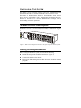
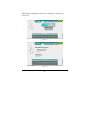
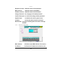
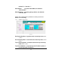
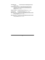
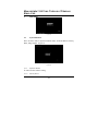
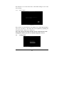
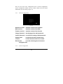
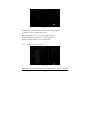
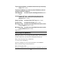
DMC-1002
SNMP Module for
Chassis-Based Media Converter
Manual
Rev. 01 (JUN. 2002)
1907MCB10016000
RECYCLABLE
TABLE
OF
C ONTENTS
ABOUT THIS GUIDE .................................................................. 2
FEATURES......................................................................................................2
UNPACKING ...................................................................................................2
CONFIGURING THE SYSTEM .......................................... 3
THE MEDIA CONVERTER CHASSIS SYSTEM ...................................................3
INSTALLING THE MANAGEMENT MODULE ....................................................3
CONFIGURE THROUGH WEB BROWSER ..........................................................4
CONFIGURATION VIA SERIAL PORT ...............................................................4
SUPPORT SNMP MANAGEMENT ....................................................................5
LED INDICATORS ..........................................................................................5
MANAGEMENT SETTING THROUGH WEB
BROWSER ............................................................................................ 6
MANAGEMENT SETTING THROUGH
TERMINAL EMULATOR...................................................... 13
WHEN FORGOT THE PASSWORD ...................................................................19
TECHNICAL SPECIFICATIONS .................................... 20
1
A BOUT T HIS G UIDE
This manual shows you how to configuring your DMC-1002 SNMP Module
for Chassis-Based Media Converter.
Features
9
9
9
9
Compliant with IEEE802.3u 100BASE-TX standards
Enable to monitor the module through terminal emulation program and
Web browser
The network administrator can access management software by
connecting the management module either to a terminal emulation
program (through the RS232 interface) or to a remote network
management station (through the RJ45 interface and a hub)
Status indication include:
1.
2.
3.
9
9
9
9
Identification of: Media Converter type; Slot number occupied
Status Indication of Chassis: Redundant Power status; Power Fail status;
Fan Fail status
Status Indication of Modules: Unit Power; Link/Activity; Transmit; Receive
LED Indication: Power/Power Fail/Fan Fail/MGM/Console/Link/ACT
Support Hot-swappable
Auto-negotiation for half-duplex/full-duplex on TX ports
Equipped with a 19” system chassis 16-converter with Redundant Power
supply for optional Expansion use.
Unpacking
Open the shipping carton of the SNMP Module and carefully unpack its
contents. The carton should contain the following items:
One DMC-1002 SNMP Module for Chassis-Based Media Converter
One RS232 cable
This Manual
If any item is found missing or damaged, please contact your local reseller for replacement.
2
C ONFIGURING T HE S YSTEM
This chapter provides network managers and system administrators with
information about how to configure the Media Converter Chassis system.
The reader of this document should be knowledgeable about network
devices, device configuration, network management, and Internet browsers.
The user is assumed to be a network administrator or manager with an
understanding of network operations.
The Media Converter Chassis system
The chassis’s first slot is for the management module as illustration on figure
1.
Figure 1. Slide in the management module in the first slot of the chassis system.
Installing the Management Module
Before Configure the chassis system, you must do the following:
z
Install the management module into the chassis. (Figure 1)
z
Connect the module to the network.
z
Boot up for SNMP management on Web browser or emulation terminal
program.
3
Configure through Web browser
The Media Converter chassis system is accessible using a Web browser (IE
explorer, Netscape Communications, etc.) to open up the chassis monitoring
system. The default IP Address for the chassis system is “192.168.1.1”, and
the default Login name and password is both “root”.
Configuration via Serial Port
The Media Converter chassis system can be accessible using a terminal or
terminal emulator attached to the RS232 serial port on the Switch too.
NOTE: (1) The serial port cable is attached directly with the device.
(2) It needs to upgrade the Terminal Emulator due to key
malfunction.
1.
Locate correct DB9 serial port cable with female DB9 connector.
2.
Attach the DB9 serial port female cable connector to the male DB9 serial
port connector on the chassis system.
3.
Attach the other end of the DB9 serial port cable to a remote
workstation.
4.
By default, the Switch uses the following serial port parameter values:
Bits per second
57600
Stop bits
1
Data bits
8
Parity
NONE
Flow Control
NONE
4
5.
The default Login name and password is both “root”.
Support SNMP Management
The Media Converter Management Module support SNMP management.
LED Indicators
The LED indicators of the Switch include Power, ALERT, HTTP, ICQ,
SMTP, SPEED, LINK/ACT and FDX/COL. The following shows the LED
indicators for the Switch along with an explanation of each indicator.
DMC- 1000i
Power On: Lights green when the power is inserted.
Power Fail: Lights Amber when the power is inserted and it is
fail.
Fan Fail:
Lights Amber when the fan is fail.
MGM:
Blinks green when the device CPU is working and
lights amber when the CPU works fail.
Console: Blinks green when the data is transmitting through
console port and blinks amber when transmitting the wrong
data.
5
Link/Act: Lights green when link to networking Ethernet and
blinks green for activity.
M ANAGEMENT S ETTING T HROUGH W EB
B ROWSER
1
Main Menu
1-1
System Function
Figure (1) Main Menu
There are four items in System Function menu, “Software Reboot, Factory
Reset, Image Update and Configuration Update. (Figure 2)
1-2
Configuration
There are three items in Configuration menu, “General Configuration,
System Configuration and SNMP Configuration. (Figure 2)
6
Figure (2) Configuration
1-1-1 Software Reboot
To reboot for the software setting.
1-1-2 CPU Factory Reset
This function is to set the CPU (DMC-1002) back to the default setting in
case of the messy setting.
1-1-3 Factory Reset
This function is to set both CPU (DMC-1002) and all system (all smart
device installed in chassis) back to the default setting in case of the messy
setting.
1-1-4 Image Update
The section is to set the TFTP Server IP Address first, and the default address
was set to “192.168.1.2”. The Image File can be updated by uploading the
image file from the TFTP server. (Figure 3.1)
Note: The content of the image file will write the whole firmware of the
management module, please be sure that the image file is correct.
7
While the file is uploading to the system, it will appear a warning sign.
(Figure 3.2)
Figure (3.1)
Figure (3.2)
8
1-1-5
Configuration Update
Figure (4)
The section is explaining how to upload and download the configure setting
of the module.
The Configuration Upload is to restore a setting file to the management
module.
The Configuration Download is to backup the setting from the management
module.
1-2-1
General Configuration
9
Figure (5)
Hardware revision: noted the version of the hardware.
BIOS revision:
noted the version of the BIOS.
Firmware revision: noted the version of the firmware.
Change Password: the changing of the admit password.
Confirm Password: to confirm the setting of admit password.
System Name:
to authorize the device system name.
Location:
to show the device where it is located.
Refresh time: to set the refreshing time of the device through
the web.
1-2-2
General Configuration
Figure (6)
MAC Address:
will show out the MAC address of the device.
IP Address:
to allocate an IP address for the device, the
10
default IP is “192.168.1.1”.
Subnet Mask:
to set the Subnet Mask, the default is
“255.255.255.0”.
Default Gateway: to set the gateway address, the default is
“192.168.1.254”.
NOTE: After configuring the system device, need to press the save
button to save the setting.
1-2-3
SNMP Configuration
Figure (7)
Get Community Name: to get the device community name (default
= public).
Set Community Name: to set the device community name (default =
private).
Trap Community Name: to authorize the device trap community
name (default = public).
Trap Host IP Address: to set the trap host IP address (same as
monitoring station IP address).
11
Cold Start trap:
to set the trap for rebooting the device
(default = enable).
Authentication Fail Trap: to set the warning trap when the
community name of the device and workstation are
different (default = enable).
Power Fail Trap:
to set the Power Fail Trap (default = enable).
Fan Fail Trap:
to set the fan fail trap (default = enable).
MC Plug-in Trap: to set the trap of the Media Converter module
if it is plugged in (default = enable).
MC Pullout Trap: to set the trap of the Media Converter module
if it is pulled out (default = enable).
12
M ANAGEMENT S ETTING T HROUGH T ERMINAL
E MULATOR
2
Main Menu
Figure (8)
2-1
System Function
There are three items in System Function menu, “Software Reboot, Factory
Reset, Image Update. (Figure 9)
Figure (9)
2-1-1
Software Reboot
To reboot for the software setting.
2-1-2
Factory Reset
13
This function is to set the device back to the default setting in case of the
messy setting.
2-1-3
Image Update
Figure (10)
The section is to set the TFTP Server IP Address first, and the default address
was set to “192.168.1.2”. The Image File can be updated by uploading the
image file from the TFTP server. (Figure 10)
Note: The content of the image file will write the whole firmware of the
management module, please be sure that the image file is correct.
2-2
Configuration
Figure (11)
14
There are four items in the Configuration menu, “General Configuration,
System Configuration, Media Converter Chassis, Media Converters Status
and Media Converters Setting. (Figure 11)
2-2-1
General Configuration
Figure (12)
Hardware revision:
noted the version of the hardware.
BIOS revision:
noted the version of the BIOS.
Firmware revision:
noted the version of the firmware.
Change Password: the changing of the admit password.
Confirm Password: to confirm the setting of admit password.
System Name:
to authorize the device system name.
Location:
to show the device where it is located.
Refresh time:
to set the refreshing time of the device
through the web.
2-2-2
System Configuration
15
Figure (13)
MAC Address: will show out the MAC address of the device.
IP Address:
to allocate an IP address for the device, the
default IP is “192.168.1.1”.
Subnet Mask: to set the Subnet Mask, the default is
“255.255.255.0”.
Default GW:
to set the gateway address, the default is
“192.168.1.254”.
NOTE: After configuring the system device, need to press the save
button to save the setting.
2-2-3
Media Converter Chassis
16
Figure (14)
The screen will show out the power status of the chassis system.
V stands for “yes” and X stands for “No”.
Plug in: indicates if Power 1 or 2 was plugged in or not.
Power Fail: indicates if the Power 1 or 2 is fail or not.
Fan Fail: indicates if the Fan 1 or 2 is fail or not.
2-2-4
Media Converters Status
Figure (15.1)
Indicates the Link, Duplex mode and Speed status of each
17
media converter.
2-2-4
Media Converters Status
Figure (15.2)
To control the linkage of each media converter.
2-3
SNMP Configuration
Figure (16)
Get Community Name:
(default = public).
to get the device community name
Set Community Name: to set the device community name (default =
private).
18
Trap Community Name: to authorize the device trap community
name (default = public).
Trap Host IP Address: to set the trap host IP address (same as
monitoring station IP address).
Cold Start trap:
to set the trap for rebooting the device (default =
enable).
Authentication Fail Trap: to set the warning trap when the
community name of the device and workstation are
different (default = enable).
Power Fail Trap:
to set the Power Fail Trap (default = enable).
Fan Fail Trap:
to set the fan fail trap (default = enable).
MC Plug-in Trap: to set the trap of the Media Converter module
if it is plugged in (default = enable).
MC Pullout Trap: to set the trap of the Media Converter module
if it is pulled out (default = enable).
Appendix A
When forgot the password
Boot up the chassis system and press the escape button repetitious three to
four times, then press “root” for login the BIOS setting, some command key
as follow: help, ls(list), sysconf (system configuration), flash, boot
Help: to check the usage of the command list.
Ls: to list out the command key.
Sysconf: to configure or view the system parameter to IIC EEPROM.
Flash: to flash the image file from TFTP server.
Boot: to boot up the system.
The usage will indicate out on the screen when the command key input error.
19
T ECHNICAL S PECIFICATIONS
General
Standards
IEEE 802.3 10BASE-T; IEEE 802.3u 100BASE-TX
Protocol
CSMA/CD
Data Transfer
Rate
100Mbps (Half-duplex)
200Mbps (Full-duplex)
Topology
Star
Network Cables
10BASE-T –
2-pair UTP Cat. 3,4,5, up to 100 m (328 ft)
100BASE-TX -2-pair UTP Cat. 5, up to 100 m (328 ft)
LED Indicator
Power (1 and 2)
Power Fail (1 and 2)
Fan Fail (1 and 2)
MGM (Green: CPU working; Blinking Amber: CPU Fail)
Console (Blinking green: Data transfer; Blinking amber:
Error Data)
Physical and Environmental
Temperature
Operating: 0° ~ 50° C, Storage: -10° ~ 70° C
Humidity
Operating: 10% ~ 90%, Storage: 5% ~ 90%
Dimensions
130 x 35 x 88 mm
EMI:
FCC Class B, CE Mark B, VCCI-B
20