1
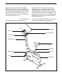
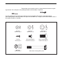
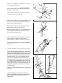
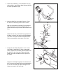
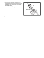
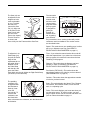
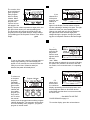
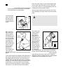
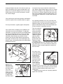
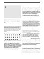
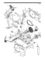
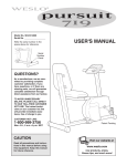
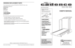
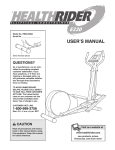
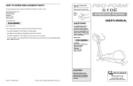
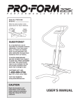
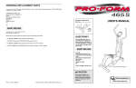
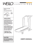
Model No. WLEX09000
Serial No.
USER'S MANUAL
Write the serial number in the
space above for reference.
Serial
Number
Decal
QUESTIONS?
As a manufacturer, we are committed to providing complete
customer satisfaction. If you
have questions, or if there are
missing parts, we will guarantee
complete satisfaction through
direct assistance from our factory.
TO AVOID DELAYS, PLEASE
CALL OUR TOLL-FREE CUSTOMER HOT LINE. The trained
technicians on our customer hot
line will provide immediate assistance, free of charge to you.
CUSTOMER HOT LINE:
1-800-999-3756
Mon.ÐFri., 6 a.m.Ð6 p.m. MST
Patent
Pending
CAUTION
Read all precautions and instructions in this manual before using
this equipment. Keep this manual
for future reference.
Visit our website at
www.weslo.com
new products, prizes,
fitness tips, and much more!
TABLE OF CONTENTS
IMPORTANT PRECAUTIONS . . . . . . . . . . . . . . . . . . . . . . . . . . . . . . . . . . . . . . . . . . . . . . . . . . . . . . . . . . . . .3
BEFORE YOU BEGIN . . . . . . . . . . . . . . . . . . . . . . . . . . . . . . . . . . . . . . . . . . . . . . . . . . . . . . . . . . . . . . . . . . .4
ASSEMBLY . . . . . . . . . . . . . . . . . . . . . . . . . . . . . . . . . . . . . . . . . . . . . . . . . . . . . . . . . . . . . . . . . . . . . . . . . . .5
HOW TO USE THE EXERCISE CYCLE . . . . . . . . . . . . . . . . . . . . . . . . . . . . . . . . . . . . . . . . . . . . . . . . . . . . . .9
MAINTENANCE AND STORAGE . . . . . . . . . . . . . . . . . . . . . . . . . . . . . . . . . . . . . . . . . . . . . . . . . . . . . . . . . .11
CONDITIONING GUIDELINES . . . . . . . . . . . . . . . . . . . . . . . . . . . . . . . . . . . . . . . . . . . . . . . . . . . . . . . . . . . .12
PART LIST . . . . . . . . . . . . . . . . . . . . . . . . . . . . . . . . . . . . . . . . . . . . . . . . . . . . . . . . . . . . . . . . . . . . . . . . . . .14
EXPLODED DRAWING . . . . . . . . . . . . . . . . . . . . . . . . . . . . . . . . . . . . . . . . . . . . . . . . . . . . . . . . . . . . . . . . .15
ORDERING REPLACEMENT PARTS . . . . . . . . . . . . . . . . . . . . . . . . . . . . . . . . . . . . . . . . . . . . . . . .Back Cover
LIMITED WARRANTY . . . . . . . . . . . . . . . . . . . . . . . . . . . . . . . . . . . . . . . . . . . . . . . . . . . . . . . . . . .Back Cover
2
IMPORTANT PRECAUTIONS
WARNING:
To reduce the risk of serious injury, read the following important precautions before using the WESLO¨ PURSUIT 616s exercise cycle.
7. Wear appropriate clothing when exercising;
do not wear loose clothing that could
become caught on the exercise cycle.
1. Read all instructions in this manual before
using the exercise cycle.
2. It is the responsibility of the owner to ensure
that all users of the exercise cycle are adequately informed of all precautions. Use the
exercise cycle only as described in this
manual.
8. Always wear athletic shoes when using the
exercise cycle.
9. Always keep your back straight when using
the exercise cycle; do not arch your back.
3. Use the exercise cycle indoors on a level
surface. Keep the exercise cycle away from
moisture and dust. Cover the floor under the
exercise cycle to protect the floor or carpet.
10. If you feel pain or dizziness while exercising,
stop immediately and begin cooling down.
11. The pulse sensor is not a medical device.
Various factors, including the user's movement, may affect the accuracy of heart rate
readings. The pulse sensor is intended only
as an exercise aid in determining heart rate
trends in general.
4. Inspect and tighten all parts regularly.
Replace any worn parts immediately.
5. Keep children under the age of 12 and pets
away from the exercise cycle at all times.
12. The exercise cycle is intended for in-home
use only. Do not use the exercise cycles in
a commercial, rental, or institutional setting.
6. The exercise cycle should not be used by
persons weighing more than 250 pounds.
WARNING: Before beginning this or any exercise program, consult your physician.
This is especially important for persons over the age of 35 or persons with pre-existing health
problems. Read all instructions before using. ICON assumes no responsibility for personal injury
or property damage sustained by or through the use of this product.
3
BEFORE YOU BEGIN
Thank you for selecting the innovative WESLO¨
PURSUIT 616s exercise cycle. The PURSUIT 616s
offers an effective form of low-impact exercise that
offers greater cardiovascular benefits and increased
muscle toning. And the PURSUIT 616s features
adjustable resistance to let you tailor your exercise to
the level thatÕs perfect for you.
Department toll-free at 1-800-999-3756, Monday
through Friday, 6 a.m. until 6 p.m. Mountain Time
(excluding holidays). To help us assist you, please
mention the product model number and serial number
when calling. The model number is WLEX09000. The
serial number can be found on a decal attached to the
exercise cycle (see the front cover of this manual for
the location of the decal).
For your benefit, read this manual carefully before
you use the PURSUIT 616s. If you have additional
questions, please call our Customer Service
Before reading further, please familiarize yourself with
the parts that are labeled in the drawing below.
Handlebar
Console
Resistance Knob
Pulse Sensor
Handlebar Post
Seat
Seat Post
Seat Pin
Pedal Strap
Pedal
Side Shield
BACK
LEFT SIDE
4
ASSEMBLY
Assembly requires two persons. Place all parts of the exercise cycle in a cleared area and remove the packing materials. Do not dispose of the packing materials until assembly is completed.
Assembly requires the included tools and your own adjustable wrench
screwdriver
.
and phillips
Use the drawings below to identify the small parts used in assembly. The number in parenthesis below
each drawing refers to the key number of the part, from the PART LIST on page 14; the second number refers to
the quantity needed for assembly. Note: Some small parts may have been pre-attached for shipping. If a
part is not in the parts bag, check to see if it has been pre-assembled.
M6 Split
Washer (54)Ð2
M8 Split
Washer (41)Ð3
M10 Split
Washer (26)Ð5
Console
Screw (20)Ð4
M6 x 8mm Button
Head Screw (40)Ð2
M10 x 19mm Button
Head Screw (25)Ð5
M8 Nylon
Locknut (24)Ð7
M8 x 63mm Carriage Bolt (47)Ð4
5
1. Hold one of the Stabilizers (46) against the saddle
on the rear of the Frame (1). Make sure that the
Stabilizer is turned so the square holes are facing away from the saddle. Attach the Stabilizer
with two M8 x 63mm Carriage Bolts (47) and two
M8 Nylon Locknuts (24).
1
24
48
1
24
Attach the other Stabilizer (not shown) to the front
of the Frame (1) in the same way.
46
48
47
2. Hold the Console Plate (11) near the Handlebar Post
(2) as shown, and feed the Resistance Cable (10)
down through the Handlebar Post.
2
11
Next, feed the Extension Wire (56) up through the
indicated hole in the Console Plate (11).
10
56
40
Attach the Console Plate (11) to the Handlebar Post
(2) with two M6 x 8mm Button Head Screws (40)
and two M6 Split Washers (54).
54
40 54
2
3. Connect the Extension Wire (56) to the wire on the
Console (8). Next, attach the Console to the
Console Plate (11) with four Console Screws (20).
3
8
9
11
Press the Resistance Knob (9) onto the Resistance
Control (10).
56
4. Hold the Handlebar Post (2) in the position shown.
Refer to the inset drawing. Make sure that the indicated nut is threaded fully onto the connector on the
Extension Cable (58). Align the slot in the nut with
the slot in the connector. Next, insert the tip of the
Resistance Cable (10) into the indicated opening,
pull up on the Resistance Cable, and insert the
Resistance Cable into the open end of the connector. Turn the nut counterclockwise one or two turns
until the Resistance Cable is held snugly in the connector. Note: If there is a clear plastic sleeve on the
Extension Cable, position the sleeve so that it covers the connector
Connect the Reed Switch Wire (13) to the Extension
Wire (56).
20
4
2
26
26
26
56
1
6
25
10
25
13
Making sure not to pinch the wires or cables,
slide the Handlebar Post (2) onto the Frame (1).
Attach the Handlebar Post with three M10 x 19mm
Button Head Screws (25) and three M10 Split
Washers (26).
10
Connector
Slot
58
Nut
58
5. Attach the Handlebar (4) to the Handlebar Post (2)
with two M10 x 19mm Button Head Screws (25) and
two M10 Split Washers (26).
5
4
2
25
26
6. Insert the Seat Post (3) into the Frame (1). Press
the Seat Post Shield (30) down onto the Frame.
6
16
Align one of the holes in the Seat Post (3) with the
hole in the Frame (1). Turn the Seat Pin (14) as
shown and insert it fully into the Frame and the Seat
Post. Make sure to insert the Seat Pin through
one of the holes in the Seat Post; do not insert
the Seat Pin under the Seat Post.
41
24
Attach the Seat (16) to the Seat Post (3) with three
M8 Nylon Locknuts (24) and three M8 Split Washers
(41). Note: The Nylon Locknuts and Split Washers
may be pre-attached to the bottom of the Seat.
41
24
30
3
14
1
7. Identify the Left Pedal (45) (there is an ÒLÓ on the
Left Pedal for identification). Using an adjustable
wrench, tighten the Left Pedal counterclockwise into
the left arm of the Crank (29). Tighten the Right
Pedal (not shown) clockwise into the right arm of
the Crank. Tighten both Pedals as fully as possible. Important: After using the exercise cycle for
one week, retighten the Pedals. For best performance, the Pedals must be kept properly tightened.
7
34
45
Tab
Adjust the Left Pedal Strap (34) to the desired position. Press the Left Pedal Strap onto the adjustment
tab on the Left Pedal (39). Adjust the Right Pedal
Strap (not shown) in the same way.
7
29
8. The Console (8) requires two ÒAAÓ batteries (not
included); alkaline batteries are recommended. Slide
off the Battery Cover (32) as shown. Press two batteries into the Console. Make sure that the negative (Ð) ends of the batteries are touching the
springs. Reattach the Battery Cover.
8
32
Clip
Batteries
8
9. Make sure that all parts are properly tightened before you use the exercise cycle. Cover the floor
under the exercise cycle to protect the floor or carpet. Note: There may be some hardware left over
after assembly is completed.
8
HOW TO USE THE EXERCISE CYCLE
HOW TO ADJUST THE SEAT
DESCRIPTION OF THE CONSOLE
The Seat (16) can
be adjusted to the
height that is the
most comfortable
16
for you. To adjust
the Seat, first
14
remove the Seat
3
Pin (14). Align one
of the holes in the
Seat Post (3) with
Frame
the hole in the
Frame (not shown).
Turn the Seat Pin
as shown and
insert it fully into the Frame and the Seat Post. Make
sure to insert the Seat Pin through one of the
holes in the Seat Post; do not insert the Seat Pin
under the Seat Post.
The innovative
console offers a
manual mode
and three motivational pacer
programs. Each
pacer program
is designed to
guide you
through an
effective workout by pacing
your exercise.
As you exercise, seven monitor modes will provide
continuous exercise feedback. The monitor modes
are described below:
SpeedÑThis mode shows your pedaling pace, in miles
per hour or kilometers per hour (see HOW TO
SELECT MILES OR KILOMETERS on page 11).
HOW TO ADJUST THE PEDAL STRAPS
To adjust the Left
Pedal Strap (34),
34
first pull the Pedal
Strap off the
adjustment tab on
the pedal. Align a
Tab
different hole in
the Pedal Strap
with the tab, and
press the Pedal
Strap back onto the tab. Adjust the Right Pedal Strap
(not shown) in the same way.
TimeÑIf you select the manual mode, this mode will
show the elapsed time. If you select one of the three
pacer programs, this mode will count down the time
remaining in the program.
HOW TO ADJUST THE PEDALING RESISTANCE
CaloriesÑThis mode shows the approximate number
of calories you have burned.
DistanceÑThis mode shows the distance you have
pedaled, in miles or kilometers (see HOW TO
SELECT MILES OR KILOMETERS on page 10).
Fat Calories (FAT CALS)ÑThis mode shows the
approximate number of fat calories you have burned
(see BURNING FAT on page 13).
The pedaling
8
resistance can
be adjusted with
9
the Resistance
Knob (9) located on the
Console (8). To
increase the
resistance, turn
the Knob clockwise; to decrease the resistance, turn the Knob counterclockwise.
ScanÑThis mode displays the Speed, Time, Distance,
Fat Calories, and Calories modes, for five seconds
each, in a repeating cycle.
PulseÑThis mode displays your heart rate when you
use the pulse sensor. To use this mode, you must
plug the pulse sensor into the console and attach it to
your ear lobe as described on page 11.
9
HOW THE PACER PROGRAMS OPERATE
3
The console offers
Actual
three motivational
pacer programs.
Each program
lasts for twenty
minutes. When
you use a pacer
Target
program, two
columns of bars
will appear in the
display. The left column represents a target pace, and
the right column shows your actual pedaling pace.
The target pace will change periodically during the
program; as the target pace changes, simply change
your pedaling pace to keep both columns at the same
height. Important: The target pace is a goal pace.
Your actual pace may be slower than the target
pace, especially during the first few months of
your exercise program. Be sure to exercise at a
pace that is comfortable for you.
If you selectActual
ed the manual
mode, go to
step 4. If you
selected one
of the pacer
programs, two
Target
columns of
bars will
appear in the display. The left column will show
one bar, indicating a relatively slow pace. The right
column will show your actual pedaling pace.
Change your pace until only one bar appears in
the right column. Each time the target pace
changes during the program, change your pedaling pace to keep both columns at the same height.
4
Before the console can be operated, two ÒAAÓ
batteries must be installed. (See step 8 on page 8.)
Turn on the power.
To turn on the power, press the on/reset button or
simply begin pedaling. The entire display will
appear for two seconds; the console will then be
ready for use. Note: If batteries were just
installed, the power will already be on.
2
Follow your progress with the seven monitor
modes.
The scan
modeÑ
Repeatedly
Mode
press the disArrows
play button
until an arrow
appears under
the word
Òscan.Ó When
the scan mode is selected, the console will display
the speed, time, distance, fat calories, and calories modes, for five seconds each, in a repeating
cycle.
STEP-BY-STEP CONSOLE OPERATION
1
Begin your workout.
Select one of the three pacer programs or the
manual mode.
The speed,
time, distance, fat
calories,
or calories
modeÑTo
select one of
these modes
for continuous
display, repeatedly press the display button until
an arrow appears below or above the desired
mode. Make sure that there is not an arrow under
the word Òscan.Ó
To select one
Program Indicator
of the pacer
programs,
repeatedly
press the program button.
The program
indicator will
show which
program you
have selected. To select
the manual
mode, press the program button until the program
indicator disappears. The programs will be selected in the following order: program 1, program 2,
program 3, manual mode.
The pulse modeÑSee HOW TO USE THE
PULSE SENSOR on page 11.
To reset the display, press the on/reset button.
10
6
Turn off the power.
To turn off the power, simply wait for about
six minutes. If the pedals are not moved and the
console buttons are not pressed for six minutes,
the power will turn off automatically.
HOW TO USE THE PULSE SENSOR
To use the pulse
sensor, first plug
the pulse sensor
wire into the jack
on the console as
shown.
Note: The pulse sensor is more accurate when worn
on the left ear lobe and when the user is sitting still.
For the best results, it is recommended that you stop
pedaling when using the pulse sensor.
After you have measured your heart rate, we recommend switching to another mode to conserve the batteries.
WARNING:
Pulse
Sensor
Wire
The pulse sensor is
not a medical device. Various factors, including the userÕs movement, may affect the
accuracy of heart rate readings. The pulse
sensor is intended only as an exercise aid in
determining heart rate trends in general.
Jack
HOW TO SELECT MILES OR KILOMETERS
Next, attach the
collar clip to your
collar or another
suitable place on
Pulse
your clothes. Rub
Sensor
your left ear lobe
for a moment with
your thumb and
index finger and
then clip the pulse
Collar
sensor onto your
Clip
ear lobe. When
your pulse is
detected, the
heart-shaped indicator in the display will begin to flash. Your heart rate will then be displayed.
If your heart rate does not appear in the display after a
few seconds, make sure that the pulse sensor wire is
fully plugged into the console. If you still donÕt get a
reading, make sure that the pulse sensor is attached
properly. It is often difficult to position the pulse sensor
on the first try, so you may have to try a few times
before you find the best position. It may be helpful to
use a mirror or a friend to find the correct position.
The console can
display distance
and speed in
either miles or
kilometers. If a
ÒKPHÓ appears in
the display, distance and speed
will be shown in
kilometers; if a
ÒKPHÓ does not
appear, distance
Screws
and speed will be
Switch
shown in miles.
To change the
unit of measurement, first remove the four indicated
screws. Lift the console a few inches and turn it over;
be careful not to pull on the wires. Next, locate the
small switch on the back of the console. Slide the
switch up or down to change the unit of measurement.
Reattach the console with the four screws. Be careful
not to pinch any of the wires.
After changing the unit of measurement, remove
one of the batteries for a few seconds and then
reinsert it. This will reset the console.
11
MAINTENANCE
Inspect and tighten all parts of the exercise cycle regularly. The exercise cycle can be cleaned with a soft,
damp cloth. To prevent damage to the console, keep
liquids away from the console and keep the console
out of direct sunlight.
Loosen but do not remove the M4 x 16mm Screw
(22). Slide the Reed Switch slightly closer to or farther
away from the Magnet, and retighten the Screw. Turn
the Crank for a moment. Repeat until the console displays correct feedback. When the Reed Switch is correctly adjusted, reattach the Left Side Shield and the
Left Pedal.
BATTERY REPLACEMENT
If the console does not function properly, the batteries
should be replaced. See assembly step 8 on page 8.
HOW TO ADJUST THE RESISTANCE STRAP
If the pedaling resistance is too low, even when the
resistance knob is turned to the maximum setting, the
Resistance Strap (12) may need to be adjusted. To
adjust the Resistance Strap, the left side shield must
first be removed, as described at the left.
TIGHTENING THE PEDALS
For best performance, regularly tighten both pedals.
HOW TO ADJUST THE REED SWITCH
Turn the resistance
knob to the lowest
setting (see HOW
TO ADJUST THE
PEDALING RESISTANCE on page 9).
Open the Strap
12
20
Buckle (57) and
57
pull the end of the
Resistance Strap
(12) slightly. Close
the Strap Buckle and turn the Flywheel (20) to make
sure that there is not too much resistance. When the
Resistance Strap is properly adjusted, re-attach the
left side shield.
If the console does not display correct feedback, the
reed switch may need to be adjusted. To adjust the
reed switch, you must first remove the Left Side Shield
(6). Using an adjustable wrench, turn the Left Pedal
(45) clockwise and remove it. Next, remove the indicated M4 x 38mm Screws (21) and M4 x 16mm
Screws (22). Grip both Side Shields and gently pull
them apart. Turn the left arm of the Crank (29) to the
position shown, and carefully slide the Left Side Shield
forward and remove it.
29
6
45
7
CRANK ADJUSTMENT
21
If the arms of the
Crank (29) become
loose, they should
be tightened in
Slotted
order to prevent
Crank Nut
excessive wear.
Loosen the Crank
35
Nuts (35) on the
29
left arm of the
Crank. Place the
tip of a standard
screwdriver in one of the slots in the slotted crank nut.
Tap the screwdriver with a hammer to turn the slotted
crank nut counterclockwise until the arms are no
longer loose. Do not overtighten the slotted crank
nut. When the slotted crank nut is properly tightened,
tighten the Crank Nuts.
22
22
With the Left
Side Shield (6)
removed, locate
the Reed Switch
(13) on the
frame. Turn the
Crank (29) until
the Magnet (23)
is aligned with
the Reed Switch.
29
22
23
13
12
CONDITIONING GUIDELINES
Burning Fat
WARNING:
Before beginning
this or any exercise program, consult your
physician. This is especially important for
individuals over the age of 35 or individuals
with pre-existing health problems.
To burn fat effectively, you must exercise at a relatively
low intensity level for a sustained period of time. During
the first few minutes of exercise, your body uses easily
accessible carbohydrate calories for energy. Only after
the first few minutes does your body begin to use
stored fat calories for energy. If your goal is to burn fat,
adjust the intensity of your exercise until your heart rate
is near the lowest number in your training zone.
The pulse sensor is not a medical device.
Various factors, including the user's movement, may affect the accuracy of heart rate
readings. The pulse sensor is intended only
as an exercise aid in determining heart rate
trends in general.
For maximum fat burning, adjust the intensity of your
exercise until your heart rate is near the middle of your
training zone.
Aerobic Exercise
The following guidelines will help you to plan your
exercise program. For more information about exercise, consult your physician or obtain a reputable
book.
If your goal is to strengthen your cardiovascular system, your exercise must be Òaerobic.Ó Aerobic exercise
is activity that requires large amounts of oxygen for
prolonged periods of time. This increases the demand
on the heart to pump blood to the muscles, and on the
lungs to oxygenate the blood. For aerobic exercise,
adjust the intensity of your exercise until your heart rate
is near the highest number in your training zone.
EXERCISE INTENSITY
Whether your goal is to burn fat or to strengthen your
cardiovascular system, the key to achieving the
desired results is to exercise with the proper intensity.
The proper intensity level can be found by using your
heart rate as a guide. The chart below shows recommended heart rates for fat burning and aerobic
exercise.
WORKOUT GUIDELINES
Each workout should include the following three
important parts: (1) a warm-up, (2) training zone exercise, and (3) a cool-down.
A Warm-UpÑBegin each workout with five to ten minutes of stretching and light exercise to warm up. A
proper warm-up increases your body temperature,
heart rate and circulation in preparation for exercise.
Training Zone ExerciseÑAfter warming up, increase
the intensity of your exercise until your heart rate is in
your training zone for 20 to 30 minutes. Breathe regularly and deeplyÑnever hold your breath.
To find the proper heart rate for you, first find your age
at the bottom of the chart (ages are rounded off to the
nearest ten years). Next, find the three numbers
above your age. The three numbers define your Òtraining zone.Ó The lowest two numbers are recommended
heart rates for fat burning; the highest number is the
recommended heart rate for aerobic exercise.
A Cool-downÑFinish each workout with 5 to 10 minutes of stretching. This will increase your flexibility and
will help to prevent post-exercise problems.
EXERCISE FREQUENCY
To maintain or improve your condition, plan three workouts each week, with at least one day of rest between
workouts. After a few months of regular exercise, you
may complete up to five workouts each week if
desired. Remember, the key to success is make exercise a regular and enjoyable part of your everyday life.
You can measure your heart rate using the pulse sensor on the console (see step 4 on page 10).
13
PART LISTÑModel No. WLEX09000
Key No. Qty.
1
2
3
4
5
6
7
8
9
10
11
12
13
14
15
16
17
18
19
20
21
22
23
24
25
26
27
28
29
30
1
1
1
1
2
1
1
1
1
1
1
1
1
1
1
1
1
2
1
4
2
11
1
7
5
5
1
1
1
1
Description
R1000B
Key No. Qty.
Frame
Handlebar Post
Seat Post
Handlebar
Foam Grip
Left Side Shield
Right Side Shield
Console
Resistance Knob
Resistance Cable/Control
Console Plate
Resistance Strap
Reed Switch/Wire
Seat Pin
Seat Post Bushing
Seat
Pulse Sensor
1 1/4Ó Round Endcap
Drive Belt
Console Screw
M4 x 38mm Screw
M4 x 16mm Screw
Magnet
M8 Nylon Locknut
M10 x 19mm Button Head Screw
M10 Split Washer
Right Pedal Strap
Right Pedal
Crank/Pulley
Seat Post Shield
31
32
33
34
35
36
37
38
39
40
41
42
43
44
45
46
47
48
49
50
51
52
53
54
55
56
57
58
#
#
1
1
2
1
1
2
2
2
2
2
3
1
1
1
1
2
4
4
1
1
1
1
1
2
3
1
1
1
1
1
Description
Crank Bearing Assembly
Battery Cover
Flywheel Bearing
Left Pedal Strap
Crank Nut
M8 Flanged Hex Nut
M6 Eyebolt
Adjustment Bracket
M6 Nut
M6 x 8mm Button Head Screw
M8 Split Washer
Flywheel
10.5mm x 118mm Spacer
Flywheel Axle
Left Pedal
Stabilizer
M8 x 63mm Carriage Bolt
Endcap
Resistance Spring
Reed Switch Clamp
M4 x 16mm Flat Head Screw
Return Spring
Cable Clamp Assembly
M6 Split Washer
M8.5 Flat Washer
Extension Wire
Strap Buckle
Extension Cable
UserÕs Manual
Allen Wrench
Note: Ò#Ó refers to a non-illustrated part. Specifications are subject to change without notice. See the back cover
of this manual for information about ordering replacement parts.
14
EXPLODED DRAWINGÑModel No. WLEX09000
32
R1000B
8
9
16
7
11
22
10
22
41
20
40
18
54
24
41
4
24
40 54
3
22
2
19
22
26
22
26
25
30
25
25
26
26
27
29
15
5
14
28
56
22
48
50
13
46
23
47
31 58
34
51
52 53
42
12
49
43
24
29
24
31
37
36 38
1
35
33
55
39
48
24
45
21
17
6
46
48
22
22
15
47
36
38
33 39
44
57
48
55
55 37
ORDERING REPLACEMENT PARTS
To order replacement parts, call our Customer Service Department toll-free at 1-800-999-3756, Monday through
Friday, 6 a.m. until 6 p.m. Mountain Time (excluding holidays). To help us assist you, please be prepared to give
the following information:
¥ The MODEL NUMBER of the product (WLEX09000)
¥ The NAME of the product (WESLO¨ PURSUIT 616s exercise cycle)
¥ The SERIAL NUMBER of the product (see the front cover of this manual)
¥ The KEY NUMBER and DESCRIPTION of the part(s) (see the PART LIST on page 14).
WESLO¨ is a registered trademark of ICON Health & Fitness, Inc.
LIMITED WARRANTY
ICON Health & Fitness, Inc. (ICON), warrants this product to be free from defects in workmanship and
material, under normal use and service conditions, for a period of ninety (90) days from the date of purchase. This warranty extends only to the original purchaser. ICON's obligation under this warranty is limited to replacing or repairing, at ICON's option, the product through one of its authorized service centers.
All repairs for which warranty claims are made must be pre-authorized by ICON. This warranty does not
extend to any product or damage to a product caused by or attributable to freight damage, abuse, misuse, improper or abnormal usage or repairs not provided by an ICON authorized service center, products
used for commercial or rental purposes, or products used as store display models. No other warranty
beyond that specifically set forth above is authorized by ICON.
ICON is not responsible or liable for indirect, special or consequential damages arising out of or in connection with the use or performance of the product or damages with respect to any economic loss, loss
of property, loss of revenues or profits, loss of enjoyment or use, costs of removal, installation or other
consequential damages of whatsoever nature. Some states do not allow the exclusion or limitation of incidental or consequential damages. Accordingly, the above limitation may not apply to you.
The warranty extended hereunder is in lieu of any and all other warranties and any implied warranties of
merchantability or fitness for a particular purpose is limited in its scope and duration to the terms set forth
herein. Some states do not allow limitations on how long an implied warranty lasts. Accordingly, the above
limitation may not apply to you.
This warranty gives you specific legal rights. You may also have other rights which vary from state to state.
ICON HEALTH & FITNESS, INC., 1500 S. 1000 W., LOGAN, UT 84321-9813
Part No. 170131 R1000B
Printed in China © 2000 ICON Health & Fitness, Inc.