1
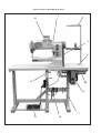
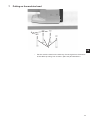
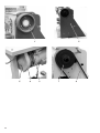
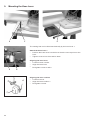
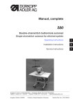
869
Spezialnähmaschine
Betriebsanleitung
Instruction manual
Postfach 17 03 51, D-33703 Bielefeld • Potsdamer Straße 190, D-33719 Bielefeld
Telefon +49 (0) 521 / 9 25-00 • Telefax +49 (0) 521 / 9 25 24 35 • www.duerkopp-adler.com
Ausgabe / Edition:
03/2009
Änderungsindex
Rev. index: 00.0
Printed in Federal Republic of Germany
Teile-Nr./Part.-No.:
0791 869741
D
GB
Alle Rechte vorbehalten.
Eigentum der Dürkopp Adler AG und urheberrechtlich geschützt. Jede, auch auszugsweise Wiederverwendung
dieser Inhalte ist ohne vorheriges schriftliches Einverständnis der Dürkopp Adler AG verboten.
All rights reserved.
Property of Dürkopp Adler AG and copyrighted. Reproduction or publication of the content in any manner, even
in extracts, without prior written permission of Dürkopp Adler AG, is prohibited.
Copyright © Dürkopp Adler AG - 2009
Foreword
This instruction manual is intended to help the user to become familiar
with the machine and take advantage of its application possibilities in
accordance with the recommendations.
The instruction manual contains important information on how to
operate the machine securely, properly and economically. Observation
of the instructions eliminates danger, reduces costs for repair and
down-times, and increases the reliability and life of the machine.
The instruction manual is intended to complement existing national
accident prevention and environment protection regulations.
The instruction manual must always be available at the machine/sewing
unit.
The instruction manual must be read and applied by any person that is
authorized to work on the machine/sewing unit. This means:
–
–
–
Operation, including equipping, troubleshooting during the work
cycle, removing of fabric waste,
Service (maintenance, inspection, repair) and/or
Transport.
The user also has to assure that only authorized personnel work on the
machine.
The user is obliged to check the machine at least once per shift for
apparent damages and to immediatly report any changes (including the
performance in service), which impair the safety.
The user company must ensure that the machine is only operated in
perfect working order.
Never remove or disable any safety devices.
If safety devices need to be removed for equipping, repairing or
maintaining, the safety devices must be remounted directly after
completion of the maintenance and repair work.
Unauthorized modification of the machine rules out liability of the
manufacturer for damage resulting from this.
Observe all safety and danger recommendations on the machine/unit!
The yellow-and-black striped surfaces designate permanend danger
areas, eg danger of squashing, cutting, shearing or collision.
Besides the recommendations in this instruction manual also observe
the general safety and accident prevention regulations!
General safety instructions
The non-observance of the following safety instructions can cause
bodily injuries or damages to the machine.
1. The machine must only be commissioned in full knowledge of the
instruction book and operated by persons with appropriate training.
2. Before putting into service also read the safety rules and
instructions of the motor supplier.
3. The machine must be used only for the purpose intended. Use of
the machine without the safety devices is not permitted. Observe all
the relevant safety regulations.
4. When gauge parts are exchanged (e.g. needle, presser foot, needle
plate, feed dog and bobbin) when threading, when the workplace is
left, and during service work, the machine must be disconnected
from the mains by switching off the master switch or disconnecting
the mains plug.
5. Daily servicing work must be carried out only by appropriately
trained persons.
6. Repairs, conversion and special maintenance work must only be
carried out by technicians or persons with appropriate training.
7. For service or repair work on pneumatic systems, disconnect the
machine from the compressed air supply system (max. 7-10 bar).
Before disconnecting, reduce the pressure of the maintenance unit.
Exceptions to this are only adjustments and functions checks made
by appropriately trained technicians.
8. Work on the electrical equipment must be carried out only by
electricians or appropriately trained persons.
9. Work on parts and systems under electric current is not permitted,
except as specified in regulations DIN VDE 0105.
10. Conversion or changes to the machine must be authorized by us
and made only in adherence to all safety regulations.
11. For repairs, only replacement parts approved by us must be used.
12. Commissioning of the sewing head is prohibited until such time as
the entire sewing unit is found to comply with EC directives.
13. The line cord should be equipped with a country-specific mains
plug. This work must be carried out by appropriately trained
technicians (see paragraph 8).
It is absolutely necessary to respect the safety
instructions marked by these signs.
Danger of bodily injuries !
Please note also the general safety instructions.
Contents
Page:
Part 2: Installation Instructions for Class 869
1.
Scope of Delivery . . . . . . . . . . . . . . . . . . . . . . . . . . . . . . . . . . . . . . . . . . . . . .
3
2.
General and Transport Packaging . . . . . . . . . . . . . . . . . . . . . . . . . . . . . . . . . . .
5
3.
3.1
3.2
3.3
3.4
3.5
3.6
3.7
3.7.1
3.7.2
3.8
Assembling the Stand
MG 55-3 stand assembly . . . . . . . . . . . . . . . . . . . . . . . . . . . .
MG 56-3 stand assembly . . . . . . . . . . . . . . . . . . . . . . . . . . . .
Completing the table plate for the MG 55-3 stand with FIR clutch motor
Completing the table plate for the MG 55-3 stand with direct drive . . .
Completing the table plate for the MG 56-3 stand with FIR clutch motor
Completing the table plate for the MG 56-3 stand with direct drive . . .
Fastening the table plate to the stand. . . . . . . . . . . . . . . . . . . . .
MG 55-3 stand . . . . . . . . . . . . . . . . . . . . . . . . . . . . . . . . . .
MG 56-3 stand . . . . . . . . . . . . . . . . . . . . . . . . . . . . . . . . . .
Assembling the supports on the table plate with cut-out (MG 55-3) . . .
.
.
.
.
.
.
.
.
.
.
6
7
8
9
10
11
12
12
13
14
4.
Setting the Working Height of the MG 55-3 stand . . . . . . . . . . . . . . . . . . . . . . . . . .
15
5.
5. 1
5.2
Sewing Drive
Drive type and application . . . . . . . . . . . . . . . . . . . . . . . . . . . . . . . . . . . . . . . . .
Components in the drive packages . . . . . . . . . . . . . . . . . . . . . . . . . . . . . . . . . . . .
16
16
6.
6.1
6.1.1
6.2
6.2.1
Mounting the set-value initiator for the
MG 55-3 stand . . . . . . . . . . . . . . . .
Aligning the pedal . . . . . . . . . . . . . .
MG 56-3 stand . . . . . . . . . . . . . . . .
Aligning the pedal . . . . . . . . . . . . . .
.
.
.
.
17
17
18
18
7.
Putting on the Machine Head. . . . . . . . . . . . . . . . . . . . . . . . . . . . . . . . . . . . . . .
19
8.
Putting on the V-belt and Tightening for the FIR Clutch Motor . . . . . . . . . . . . . . . . .
21
9.
Mounting the Knee Lever . . . . . . . . . . . . . . . . . . . . . . . . . . . . . . . . . . . . . . . . .
22
10.
10.1
10.2
10.3
10.4
Mounting the Direct Drive
Mounting the motor and putting on the V-belt . .
Connecting the Hall sensor . . . . . . . . . . . . .
Mounting the operating panel . . . . . . . . . . .
Mounting the sewing light (optional equipment).
24
24
26
27
direct
. . . .
. . . .
. . . .
. . . .
drive
. . . .
. . . .
. . . .
. . . .
.
.
.
.
.
.
.
.
.
.
.
.
.
.
.
.
.
.
.
.
.
.
.
.
.
.
.
.
.
.
.
.
.
.
.
.
.
.
.
.
.
.
.
.
.
.
.
.
.
.
.
.
.
.
.
.
.
.
.
.
.
.
.
.
.
.
.
.
.
.
.
.
.
.
.
.
.
.
.
.
.
.
.
.
.
.
.
.
.
.
.
.
.
.
.
.
.
.
.
.
.
.
.
.
.
.
.
.
.
.
.
.
.
.
.
.
.
.
.
.
.
.
.
.
.
.
.
.
.
.
.
.
.
.
.
.
.
.
.
.
.
.
.
.
.
.
.
.
.
.
.
.
.
.
.
.
.
.
.
.
.
.
.
.
.
.
.
.
.
.
.
.
.
.
.
.
.
.
.
.
.
.
.
.
.
.
.
.
.
.
.
.
.
.
.
.
.
.
.
.
.
.
.
.
.
.
.
.
.
.
.
.
.
.
.
.
.
.
.
.
.
.
.
.
.
.
.
.
.
.
.
.
.
.
.
.
.
.
.
.
.
.
.
.
.
.
.
.
.
.
.
.
.
.
.
.
.
.
.
.
.
.
.
.
.
.
.
.
.
.
.
.
.
.
.
.
.
.
.
.
.
.
.
.
.
.
.
.
.
.
.
.
.
.
.
.
.
.
.
.
.
.
.
.
.
.
.
.
.
.
.
.
.
.
.
.
.
.
.
.
.
.
.
.
.
.
.
.
.
.
.
.
.
.
GB
Contents
Page:
11.
11.1
11.2
11.2.1
11.2.2
11.3
11.4
11.4.1
11.4.2
11.4.3
11.4.4
11.5
11.5.1
11.5.2
11.5.3
11.5.4
11.5.5
11.5.6
11.5.7
Electrical Connections
General . . . . . . . . . . . . . . . . . . . . . . . . . . . . . . . . . .
Earthing . . . . . . . . . . . . . . . . . . . . . . . . . . . . . . . . .
Machine head . . . . . . . . . . . . . . . . . . . . . . . . . . . . . .
Knee switch . . . . . . . . . . . . . . . . . . . . . . . . . . . . . . .
Checking the mains supply voltage . . . . . . . . . . . . . . . . .
Connecting the clutch motor (FIR) to the mains voltage . . . . .
Rotational direction of the clutch motor. . . . . . . . . . . . . . .
Checking the rotational direction . . . . . . . . . . . . . . . . . .
Changing the rotational direction . . . . . . . . . . . . . . . . . .
Connecting the sewing light transformer (optional equipment) .
Connecting the DC positioning drive to the mains voltage . . .
Connecting the sewing machine head . . . . . . . . . . . . . . .
Connecting the DA321G control unit . . . . . . . . . . . . . . . .
Checking the rotational direction of the DC positioning drive . .
Checking the positioning . . . . . . . . . . . . . . . . . . . . . . .
Machine-specific parameters . . . . . . . . . . . . . . . . . . . . .
Master reset . . . . . . . . . . . . . . . . . . . . . . . . . . . . . . .
Connecting the sewing light on the DA321G control unit . . . .
.
.
.
.
.
.
.
.
.
.
.
.
.
.
.
.
.
.
28
28
28
29
30
30
31
31
31
32
33
33
34
35
36
36
37
38
12.
Pneumatic Connections . . . . . . . . . . . . . . . . . . . . . . . . . . . . . . . . . . . . . . . . . .
39
13.
Lubrication . . . . . . . . . . . . . . . . . . . . . . . . . . . . . . . . . . . . . . . . . . . . . . . . . .
41
14.
Sewing Test. . . . . . . . . . . . . . . . . . . . . . . . . . . . . . . . . . . . . . . . . . . . . . . . . .
42
.
.
.
.
.
.
.
.
.
.
.
.
.
.
.
.
.
.
.
.
.
.
.
.
.
.
.
.
.
.
.
.
.
.
.
.
.
.
.
.
.
.
.
.
.
.
.
.
.
.
.
.
.
.
.
.
.
.
.
.
.
.
.
.
.
.
.
.
.
.
.
.
.
.
.
.
.
.
.
.
.
.
.
.
.
.
.
.
.
.
.
.
.
.
.
.
.
.
.
.
.
.
.
.
.
.
.
.
.
.
.
.
.
.
.
.
.
.
.
.
.
.
.
.
.
.
.
.
.
.
.
.
.
.
.
.
.
.
.
.
.
.
.
.
.
.
.
.
.
.
.
.
.
.
.
.
.
.
.
.
.
.
.
.
.
.
.
.
.
.
.
.
.
.
.
.
.
.
.
.
.
.
.
.
.
.
.
.
.
.
.
.
.
.
.
.
.
.
.
.
.
.
.
.
.
.
.
.
.
.
.
.
.
.
.
.
.
.
.
.
.
.
.
.
.
.
.
.
.
.
.
.
.
.
.
.
.
.
.
.
.
.
.
.
.
.
.
.
.
.
.
.
.
.
.
.
.
.
.
.
.
.
.
.
.
.
.
.
.
.
.
.
.
.
.
.
.
.
.
.
.
.
.
.
.
.
.
.
.
.
.
.
.
.
.
.
.
.
.
.
.
.
.
.
.
.
.
.
.
.
.
.
.
.
.
.
.
.
.
.
.
.
.
.
1.
Scope of Delivery
Sewing machine with MG 55-3 stand
2
1
3
GB
4
5
10
9
8
7
Sewing machine with MG 56-3 stand
2
1
12
3
4
13
10
11
7
8
14
The items that are supplied depend on your order.
Before setup, please check that all the required components are
present.
The description is valid for the special sewing machine whose
individual components are delivered directly and completely from
Dürkopp Adler AG.
–
1
Machine head
Dürkopp Adler accessory with:
– 2 Reel stand
Protective cover (not shown)
Electric parts set, depending on your order, for:
Machines with direct drive
– 3 Protective belt cover
– 11 DA control unit
–
12 Operating panel
–
13 Knee switch
GB
Machines with clutch motor (FIR)
– 3 Protective belt cover
– 5 Main switch
–
6
Sewing drive
–
9
Knee lever
Optional equipment
– 4 Table plate (optional)
– 7 Stand (optional)
2.
–
8
–
10 Drawer (optional)
–
14 Maintenance unit (optional)
Pedal and rods (optional)
General and Transport Packaging
CAUTION !
The special sewing machine may only be set up by trained personnel.
Transport packing
After purchasing a mounted sewing machine, you must remove the
following packaging:
– Safety straps and battens from the upper machine head, table and
stand.
– Safety blocks and straps from the sewing drive.
5
3.
Assembling the Stand
There are two stand sets with different table plates available for the
669 class:
Stand set
MG 55-3
MG 56-3
3.1
Version
not separated, with or without cut-out
separated, hinged
MG 55-3 stand assembly
4
3
1
2
–
–
–
–
–
–
–
6
Assemble the stand according to the illustration.
Fasten the pedal 2 to the stand brace 1.
Mount the stand brace 1 to the stand.
Align the pedal after you have assembled the complete machine.
Screw on the holder for the oil can 3.
Turn the adjusting screw 4 to ensure a secure mount on the stand.
The stand must be resting with all four feet on the floor.
3.2
MG 56-3 stand assembly
5
4
4
6
GB
3
2
–
–
–
–
–
–
–
1
Assemble the stand according to the illustration.
Fasten the pedal 2 to the stand brace 1.
Mount the stand brace 1 to the stand.
Turn the adjusting screws 4 to ensure a secure mount on the stand.
The stand must be resting with all six feet on the floor.
Align the pedal after you have assembled the complete machine.
Screw on the holder for the oil can 5.
Assemble the rod 6 (only for FIR clutch motor).
7
3.3
Completing the table plate for the MG 55-3 stand with FIR clutch motor
Top view of table plate
6
5
7
(4x20) x2
Marking for stand
(3,5x17) x2
4
3
–
–
–
–
–
–
–
–
(4x20) x2
(3,5x17) x2
2
(5x25) x2
Turn over the table plate 4.
Screw on the cable duct 1.
Screw on main switch 2.
Screw on the power supply (optional equipment).
Screw on the drawer 5 together with its fixtures.
Screw on the sewing light transformer (optional equipment).
Mount the clutch motor 7.
For this, screw the three hexagon bolts (M8 x 40) with washers into
the anchor nuts on the table plate.
The belt pulley 8 must point to the right when the table plate is
mounted.
Mount the electrical cable according to the instructions in
chapter 12.
4
7
8
8
1
3.4
Completing the table plate for the MG 55-3 stand with direct drive
Top view of table plate
7
8
(4x20) 2x
1
6 (3,5x17) 6x
(3,5x17) 2x
Marking for stand
2
5
4
–
–
–
–
–
–
–
–
–
GB
3
(4x20) 2x
Turn over the table plate 5.
Screw on the cable duct 1.
Screw on the motor control 2.
Screw on the power supply 3.
Screw on the knee switch for the sewing-foot stroke.
(Only for subclasses 869-180322, 869-280322)
Screw on the set value initiator 8 (refer to chapter 6.1).
Screw on the drawer 6 together with its fixtures.
Screw on the sewing light transformer 7 (optional equipment).
Mount the electrical cable according to the instructions in
chapter 12.
9
3.5
Completing the table plate for the MG 56-3 stand with FIR clutch motor
Top view of table plate
1 (4x20) 2x
2
7 (5x25) 2x
3 (3,5x17) 2x
Marking for
stand
8
7 (5x25) 2x
–
–
–
–
–
–
–
–
–
4 (3,5x17) 6x
6 (4x20) 2x
Turn over the table plate 8.
Screw on the sewing light transformer 1 (optional equipment).
Screw on the cable duct 3.
Screw on the drawer 4 together with its fixtures.
Screw on the main switch 5.
Screw on the power supply 6 (optional equipment).
Screw on flap trays 7 using two wood screws per tray.
Mount the clutch motor 2.
For this, screw the three hexagon bolts (M8 x 40) with washers into
the anchor nuts on the table plate.
The belt pulley 9 must point to the left when the table plate is
mounted.
Mount the electrical cable according to the instructions in
chapter 12.
9
10
5 ,5x25) 2x
2
3.6
Completing the table plate for the MG 56-3 stand with direct drive
Top view of table plate
6 (4x20) 2x
7 (5x25) 2x
8 (3,5x17) 2x
Marking for stand
1 (3,5x17) 6x
5
7 (5x25) 2x
–
–
–
–
–
–
–
–
–
4
3 (4x20) 2x
GB
2
Turn over the table plate 5.
Screw on the drawer 1 together with its fixtures.
Screw on the motor control 2.
Screw on the power supply 3.
Screw on flap trays 7 using two wood screws per tray.
Screw on the knee switch 4 for the sewing-foot stroke.
Screw on the sewing light transformer 6 (optional equipment).
Screw on the cable duct 8.
Mount the electrical cable according to the instructions in
chapter 12.
11
3.7
3.7.1
Fastening the table plate to the stand
MG 55-3 stand
1
2
4
3
–
–
–
–
–
12
Fasten the stand 4 to the table plate 1 using wood screws (6x30).
Pre-drill the holes for the wood screws.
Be sure to note the marking for the stand
(refer to chapters 3.3, 3.4).
Turn the stand 4 so that it is in its normal position.
Attach the rod 3 onto the pedal and motor.
Put the reel stand 1 into the drilled hole in the table plate.
Fasten with nut and washer.
Mount and align the reel holder and unwind holder.
These two holders must be positioned on top of each other.
3.7.2
MG 56-3 stand
1
8
2
7
GB
3
4
5
6
–
–
–
–
–
–
Fasten the table plate 2 to the stand 5 using wood screws (6x30).
Pre-drill the holes for the wood screws.
Be sure to note the marking for the stand (refer to chapters 3.5,
3.6).
Fasten the table plate 8 to the latch 7 using three wood screws
(5x30).
Attach the rod 6 onto the pedal and the actuating lever 4 (only for
FIR clutch motor).
Attach the rod 3 onto the actuating lever 4 and motor.
Put the reel stand 1 into the drilled hole in the table plate. Fasten
with nut and washer.
Mount and align the reel holder and unwind holder.
These two holders must be positioned on top of each other.
13
3.8
Assemble support on table plate with cut-out (MG 55-3)
1
2
3
In order to increase the stability of the right side of the table plate 1,
the plate is support by a junction bar.
– Fasten junction bar 2 to the stand using screw 3. Fasten bar to the
bottom of the table plate using two wood screws (5x30).
14
4.
Setting the working height of the MG 55-3 stand
1
GB
Caution: Risk of injury !
Ergonomic-related, operator injuries can result if the stand height
is not adjusted to fit the operator.
–
–
–
–
The working height is adjustable between 750 mm and 900 mm
(measured to the upper edge of the table plate).
Loosen the screws 1 in the stand spars.
Adjust the table plate vertically to your required height.
Be sure to adjust (pull out and push in) both sides of the table plate
equally so that it does not tilt.
Tighten screws 1.
15
5.
5. 1
Sewing Drive
Driver type and application
The following types of sewing drives are available:
Subclass
Clutch motor
DCpositioning drive
869-180010
869-280020
FIR 1147*.752.3 *
FIR 1148*.752.3
Efka DC 1550/DA321G
869-180122
869-280122
Efka DC 1550/DA321G
869-180322
869-280322
Efka DC 1550/DA321G
* This clutch motor has an electro-magnetic brake which quickly stops
the rotor after the motor has been turned off. This prevents the sewing
machine from running if the pedal is pressed shortly after the machine
has been turned off.
5.2
Components in the drive packages
Your requested drive is delivered in the form of a “drive package”. This
package includes not only the sewing drive but also belt pulley, V-belt,
connection cables, pedal rod, fastening materials and diagrams.
16
6.
6.1
Mounting the Set-value Initiator for the Direct Drive
MG 55-3 stand
4
3
GB
1
2
–
–
–
6.1.1
Screw the angle bracket 3 under the table plate 4 (refer to
chapter 3.4).
Screw the set-value initiator onto the angle 3.
Hang the rod 2 on the set-value initiator and pedal.
Aligning the pedal
–
–
–
Loosen screw on the rod 2.
Adjust the height of the pedal rod so that the released (unused)
pedal has a decline of about 10°.
Tighten the screw on the rod 2.
17
6.2
MG 56-3 stand
4
5
3
1
2
–
–
6.2.1
Aligning the pedal
–
–
–
18
Screw the set-value initiator 3 onto the plate 5 on stand 1 using two
screws 4 (M6 x 80).
Hang the rod 2 on the set-value initiator 3 and pedal.
Loosen screw on the rod 2.
Adjust the height of the pedal rod so that the released (at rest)
pedal has a decline of about 10°.
Tighten the screw on the rod 2.
7.
Putting on the machine head
2
1
GB
–
Put the machine head on the table top. Screw tight from the bottom
of the table top using four screws 1 (M8 x 50) and washers 2.
19
1
5
20
4
2
3
7
6
8.
Put the V-belt on and tighten for the FIR clutch motor
Take off the protective cover.
– Remove handwheel 1.
– Remove the protective belt cover 4 on the sewing drive.
Put on the V-belt and mount the protective cover.
– Fasten the belt pulley (in the drive package) to the shaft of the
sewing drive.
– Put the V-belt 6 on the belt pulley 7 located on the machine head.
– Guide the V-belt 6 downwards through the cut-out in the table
plate.
– Loosen the screw 3 on the base of the sewing drive.
– Put the V-belt 6 on the sewing drive’s belt pulley.
– Mount the protective belt cover 2 on the machine head.
– Mount the handwheel 1.
Tightening the V-belt
– Loosen the screw 3 on the base of the sewing drive.
– Tighten the V-belt by swivelling out the sewing drive.
When the belt has the correct tension, you should be able to press
down with your finger in the middle of the belt 6 (without excessive
force) so that the belt moves about 10 mm down.
– Tighten screw 3.
Assembling the protective belt cover on the sewing drive
– Adjust the belt run-off safeguard 5 (an adjustable angle or cam,
depending on the drive type) on the belt cover 4 as follows:
When the machine head is tilted back, the V-belt 6 must remain on
the belt pulley.
Also refer to the operating instructions from the motor
manufacturer.
– Screw on the lid of the belt cover 4.
21
GB
9.
Mounting the Knee Lever
2
1
3
The sewing feet can be lifted mechanically by the knee lever 1.
Attach the knee lever 1.
– Position the knee lever from below so that the nose 2 points to the
front.
– Tighten screw 3 into the machine base.
Aligning the knee lever
– Loosen screws 4 and 5.
– Align the knee lever.
– Re-tighten screws 4 and 5.
5
4
6
7
22
Aligning the knee cushion
– Loosen screw 6.
– Align the knee cushion 7.
– Re-tighten screw 6.
Notes:
GB
23
10. Mounting the Direct Drive
10.1 Mounting the motor and putting on the V-belt
5
1
–
–
–
–
4
3
Unscrew the handwheel 1.
Screw motor 3 onto the head using two screws 4 (M6 x 16) so that
it can be easily shifted.
Put on the V-belt 5.
Tighten the V-belt.
Press the motor 3 downwards and tighten both screws 4.
When the belt has the correct tension, you should be able to press
down with your finger in the middle of the belt 6 (without excessive
force) so that the belt moves about 10 mm down.
10.2 Connecting the Hall sensor
Caution: Risk of injury !
Turn the main switch off.
Connect the Hall sensor only with the sewing machine turned off.
7
6
–
24
Screw off the arm cover 7 and valve cap 6.
14
9
11
15
10
8
11
–
–
–
–
–
12
–
–
–
Fasten the Hall sensor 15 to the holder 8 using two screws 14
(M4 x 5).
Fasten the holder 8 with the Hall sensor 15 to the arm 8 using two
screws 10 (M4 x 8).
Guide the cable 11 through the clips 9.
Route cable 11 in the arm and then to the control cabinet under the
table plate.
Screw on the arm cover 7.
Connect the 9-pole Sub-D plug from the Hall sensor into “B18"
socket on the Efka DA321G controller (IPG / HSM / LSM).
2
13
Take out the section 12 from the protective belt cover 2.
Use a sharp knife to cut through the sections shown by 13.
Mount the protective belt cover on the machine head.
Mount the handwheel 1.
25
GB
10.3 Mounting the operating panel
3
2
1
–
–
–
–
–
26
5
Screw on operating panel 1 along with the thread guide 2.
Take off the valve cap 3.
Lay the panel’s connection cable 5:
Pull the cable in the arm and then downwards through the opening
in the table plate.
Plug in the cable plug into the B776 socket on the drive controller.
Put the valve cap 3 back on.
10.4 Mounting the sewing light (optional equipment)
CAUTION !
The power supply to the sewing light is not disconnected when the
main switch is turned off. Remember to pull out the mains plug before
making this connection.
5
4
2
3
GB
6
2
7
1
The sewing light 1 will be mounted on the arm cover 2.
– Screw off the arm cover 2.
– Use a 4.5-mm Ø bit to drill the fastening holes 3.
– Screw the retainer piece 5 using screw 4.
– Put the sticker with the safety notice on the front of the main
switch 7.
– Put the sewing light onto the retainer piece 5.
– Unscrew the valve cap 6.
– Route the sewing light’s supply cable into the cut-out on the
machine arm.
– Guide the the connection cable downwards through the opening in
the table plate.
– Fasten the sewing light transformer under the table plate using
particle-board screws.
– Plug in the connector for the transformer’s power supply.
– Put on the cover 2 and valve cap 6.
27
11. Electrical Connections
11.1 General
Caution!
All work on the electrical equipment of the sewing machine may only
be carried out by qualified electricians or other appropriately trained
persons.
The power cord must always be disconnected while working on the
electrical equipment!
11.2 Earthing
11.2.1
Machine head
2
1
3
3
1
The earth (grounding) cable 1 is included in the machine’s accessory
pack.
The earth cable 1 conducts static charges from the machine head via
the motor foot to the earth.
– Connect the earth cable 1 to the tab connector 2 (connector is
already screwed on to the machine head). Then route the cable
through the cable duct to the motor foot.
– Screw the earth cable 1 to the motor foot or control unit box using
screw 3.
– The earth cable 1 should also be fastened under the table plate
with nail clips.
Caution!
Make sure that the earth cable 1 does not come into
contact with the V-belt.
Note:
For sewing machines with a sewing drive integrated into the machine
head, there is no need to establish equipotential bonding since this is
implemented with the attached motor.
28
11.2.2
Knee switch
3
2
–
–
1
Fasten the large eyelet on the earth cable 1 to the knee switch
using screw 2.
Screw the earth cable 1 to the control unit box using screw 3.
GB
29
11.3 Checking the mains supply voltage
Caution!
The nominal voltage given on the sewing drive’s identification plate
must correspond to the mains voltage where it is to be operated.
11.4 Connecting the clutch motor (FIR) to the mains voltage
Caution!
A pluggable connection must be used to connect the sewing machine
to the mains supply voltage!
The clutch motor should be connected to three-phase current:
3 x 380 - 415V 50/60Hz or 3 x 220 - 240V 50/60Hz.
(Refer to the table in chapter 5.2.)
The connection should be established according to the connection
diagrams 9800 110002 A or 9800 120009 D.
–
–
30
Route the connection cable from the main switch through the cable
duct to the sewing drive. Then connect the cable to the sewing
drive.
Refer to the connection diagram 9800 110002 A/ 9800 110002 D (in
the accessories) or to the circuit diagram on the clutch motor.
Route the voltage supply cable from the main switch through the
cable duct to the rear. Then fasten with the strain relief mechanism.
11.4.1
Rotational direction of the clutch motor
Caution!
Make sure to check the rotational direction of the sewing drive before
initial commissioning of the sewing machine!
Operating the sewing machine with the incorrect rotational direction
can damage the machine.
11.4.2
Checking the rotational direction
The rotational direction of the clutch motor (a three-phase motor) is
dependent on the three-phase mains connection and the method of
assembly used. In order to check the rotation before use, do the
following:
– Connect the clutch motor. Establish equipotential bonding. Connect
the sewing drive to the mains supply.
(Refer to chapters 11.2 and 11.4.)
– Turn the main switch on.
– Press the pedal (or the motor’s clutch lever) until the belt pulley
starts to turn.
– The handwheel must rotate in the direction of the arrow.
11.4.3
Changing the rotational direction
If the sewing drive is turning in the false direction, then you must swap
two phases at the mains terminals for the sewing drive. Take the
following steps:
– Turn off the main switch and unplug the mains plug!
– Swap the positions of two of the three phase wires at the sewing
drive’s mains connection.
– Plug in the mains plug and switch on the main switch.
– Re-check the rotational direction (refer to chapter 11.4.2).
31
GB
11.4.4
Connecting the sewing light transformer (optional equipment)
2
1
CAUTION !
The transformer for the sewing light is connected directly to the mains
power supply and is live even when the main switch has been turned
off.
Always pull out the mains plug before starting any work on the
transformer (for example, when changing the fuse).
–
–
Pull out the mains plug of the sewing machine!
Route the mains cable 1 for the transformer 2 through the cable
duct 3 to the main switch.
Make the connection on the mains side of the main switch (or motor
protective switch).
Refer to connection diagram 9800 169002 B.
– Put the sticker with the safety notice on the front of the main
switch.
A neutral conductor must be used if you are connecting the transformer
to a three-phase 3 x 380V - 415 V power supply.
32
11.5 Connecting the DC positioning drive to the mains voltage
Caution!
A pluggable connection must be used to connect the sewing machine
to the mains supply voltage!
The DC positioning drive is run with single-phase AC current of
190 - 240V 50/60Hz. The connection should be made according to the
connection diagram 9800 120009 A or 9800 130014 R.
When connecting to a three-phase supply of 3x380V, 3x400V or
3x415V, the sewing drive should be connected to one phase and to a
neutral conductor.
When connecting to a three-phase supply of 3x200V, 3x220V, 3x230V
or 3x240V, the sewing drive should be connected to two of the phases.
If multiple DC positioning drives need to be connected to the same
three-phase supply, you should distribute the connections amongst all
of the phases equally so that no single phase is overloaded.
11.5.1
Connecting the sewing machine head
–
–
The cable numbered 9870 867000 is plugged into the head
distributor 9850 867000. This cable is then routed downwards
inside the head.
The 37-pole plug on the cable should be connected and screwed in
to socket A on the sewing drive.
33
GB
11.5.2
Connecting the DA321G control unit
3
4
KN19
2
1
–
–
–
–
–
–
–
–
34
Plug the cable from the setpoint director device (pedal) into the
B80 socket on the control unit.
Plug the motor sensor cable 1 into the B2 socket on the controller.
Plug the motor cable 2 into the B41 socket on the controller.
Plug the cable leading to the sewing machine into the A socket on
the controller.
Route all cables through the cable duct.
Plug the cable from the operating panel (if available) into the B776
socket.
Plug the cable 3 from the knee switch into the KN19 socket on the
front side.
Use the clips 4 to fasten down the cable 3 (only with 869-180322
and 869-280322 ).
11.5.3
Checking the rotational direction of the DC positioning drive
CAUTION !
Make sure to check the rotational direction of the sewing drive before
commissioning the sewing machine. Operating the sewing machine
with the incorrect rotational direction can damage the machine.
The arrow on the belt cover indicates the machine’s proper
direction of rotation.
A reset value in the control unit parameter defines the rotational
direction of the handwheel as counter-clockwise. This specifies the
rotational direction of the DC positioning motor. However, the rotational
direction must be verified before the initial commissioning of the
machine. Take the following steps:
–
–
–
–
–
–
–
–
Set the sewing foot in the high position.
The plugs from the set-value initiator, motor, motor sensor and
operating panel (if present) must be connected.
The 37-pole plug from the sewing machine head should not be
plugged in.
Turn the main switch on.
The operating panel displays “Inf A5" or ”A5". This means that a
valid “Auto-select resistant” has not been detected. The maximum
rotational speed will therefore be limited.
Press down gently forwards on the pedal.
The drive starts to turn.
Check the rotational direction.
If the rotational direction of the drive is incorrect, then you must set
the technical-level parameter “161" to a value of 1.
(Refer to the instructions from the drive manufacturer.)
Turn the main switch off.
Reconnect the 37-pole plug from the sewing machine head
35
GB
11.5.4
Checking the positioning
The needle position should already be properly set upon arrival of the
sewing machine. However, the needle position should be checked
before starting up the machine.
Prerequisite
·
·
The sewing foot should be set in the high position. (Refer to the
operating instructions).
The machine should be set to stop over position 1 (with the needle
down).
Position 1
– Turn the main switch on.
– Press forward on the pedal briefly and then return to starting
position.
The needle is in position 1.
– Check the position of the needle.
Position 2
(only with switched-off reverse rotation (parameter 182 set to 0)
– Press the pedal first forward and then completely back.
The needle is in position 2 (thread lever is at top dead centre).
– Check the position of the thread lever.
If one or both needle positions are incorrect, then you must correct the
positioning. (Refer to the operating instructions.)
11.5.5
Machine-specific parameters
General
The programming and setting of parameters are used to specify the
functions of the sewing drive controller.
Auto-select
The controller detects which sewing machine class is connected by
measuring the auto-select resistance from the machine. Auto-select is
used to select the control functions and the pre-set values of the
parameters.
CAUTION !
If the controller detects an invalid or absent auto-select resistance,
then the sewing drive will only operated with emergency-run functions.
This serves to protect the machine from damage.
–
36
The correct machine class can be set using parameter F-290, in
accordance with the parameter data sheet 9800 331104 PB50.
In order to ensure that the machine is properly positioned and that all
functions are correct, the following parameters must be verified or set
correctly:
·
·
·
Parameter F-111: set to 3000 rpm or less.
Parameter F-270: set to 6 (selection of positioning sensor)
Parameter F-272: calculate with the following formula:
Diameter of the motor belt pulley
x 1000
Diameter of the machine belt pulley
11.5.6
Master reset
A master reset will reset all parameter values to their default settings.
After a master reset, the machine-specific parameters must be
correctly specified again.
GB
37
11.5.7
Connecting the sewing light on the DA321G control unit
2
6
5
–
–
–
–
–
–
–
–
–
–
38
1
6
5
4
3
Loosen the four screws on the front plate of the control unit.
Take off the front plate.
Push the cable from the rear through the cable duct 1 in the
controller.
Take off the black rubber guide track 2.
Use a screwdriver to punch though the circular opening in the
guide track.
Guide the cable for the sewing light transformer through this new
opening.
Replace the guide track.
Use a thin screwdriver to press on the terminal openings 4 and 3.
This opens up the terminals 5 and 6.
Connect the blue cable to terminal 6 and the brown cable to
terminal 5.
Reattach the front plate using the four screws.
12. Pneumatic Connections
CAUTION !
The pneumatic equipment will only function smoothly when the
system’s supply pressure in between 8 and 10 bar.
The operating pressure of the sewing machine is 6 bar.
Pneumatic connection package
You can order a pneumatic connection package (order number
0797 003031) for stands with compressed-air maintenance units.
The package contains the following components:
– Connection hose, 5 m long, (Ø =9 mm)
– Hose connector gland and hose fitting
– Coupling socket and coupling plug
GB
1
Connecting the compressed-air maintenance unit
–
–
Fasten the compressed-air maintenance unit 1 to the stand brace
using the angle bracket, screws and strap.
Connect the maintenance unit to the compressed air supply using a
connection hose 5 (Ø =9 mm) and a R1/4" hose coupling.
39
2
3
6
4
8
2
10
4
5
6
7
Connecting the maintenance unit to the sewing machine head
– Unscrew the cap 6.
– Connect hose 3 (in accessory pack) with the distributor plate 7
located on the machine head.
– Screw the cap 6 back on.
Setting the operating pressure
The operating pressure is 6 bar.
It can be read using the pressure gauge 4.
– In order to set the pressure, pull up on the turning handle 2 and
turn.
In order to raise the pressure, turn the handle 2 clockwise. In order
to decrease the pressure, turn the handle 2 counter-clockwise.
40
13. Lubrication
1
2
3
Caution: Risk of injury !
Oil can cause skin rashes.
Avoid prolonged skin contact.
If oil or grease contacts your skin, wash yourself thoroughly.
GB
CAUTION !
The handling and disposal of mineral oils is subject to legal
constraints.
Deliver used oil to an authorized reception point.
Protect your environment.
Take care not to spill any oil.
Oil the sewing machine exclusively with the lubricating oil DA-10 or
equivalent oil with the following specification:
– Viscosity at 40° C :
10 mm²/s
– Flash point:
150° C
DA-10 can be purchased at sales branches of
DÜRKOPP ADLER AG, under the following part numbers:
250-ml container: 9047 000011
1 litre container: 9047 000012
2 litre container: 9047 000013
5 litre container: 9047 000014
Lubricating the machine head (for the initial filling)
Note
All wicks and felt in the head are saturated with oil before being
delivered. This oil is carried back to the storage reservoir 1.
Do not overfill the reservoir.
– Fill oil into the reservoir 1 using the hole 2. Fill until you reach the
“min.” mark 3.
41
14. Sewing test
After setup is complete, a sewing test must be carried out.
–
Plug in the power supply plug.
Caution: Risk of injury !
Turn the main switch off.
The needle thread and shuttle thread must be threaded only when
the machine is turned off.
–
–
–
–
–
–
–
–
–
42
Thread in the winder thread (refer to the operating instructions,
chapter 6.11).
Turn the main switch on.
Set the sewing feet in their raised positions (refer to operating
instructions, chapter 6.11).
Fill up the bobbin winder at low speed.
Turn the main switch off.
Thread in the needle and bobbin thread (refer to operating
instructions, chapters 6.1 and 6.6).
Select the material to be processed.
Carry out the sewing test – initially with a slow speed and then
continually accelerating.
Check that the seams satisfy requirements.
If your requirements are not met, change the thread tension (refer
to the operating instructions, chapters 6.2, 6.4 and 6.7).
If necessary, the settings detailed in the service instructions should
also be checked and corrected.