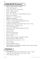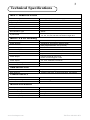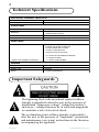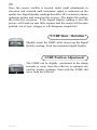
1
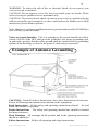
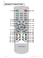
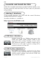
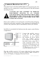
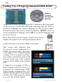
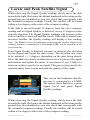
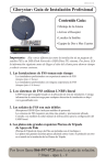
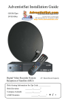
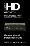
The receiver has a serial number located on the rear panel.
Record the serial numbers, date of purchase and retain for your
records.
Serial number
_____________________________________
Reseller Name _____________________________________
Purchase Date
_____________________________________
Note: Save all original boxes, manuals, accessories and
packaging materials in case it is necessary to return the
merchandise.
Before unpacking or assembly of any item, review the
warranty, exchange and refund policies provided by your
reseller.
DTV Transition Notice After February 17, 2009, a television receiver with only an analog broadcast tuner will
require a converter box to receive full power over-the-air broadcasts originating from a
United States broadcaster with an antenna because of the Nation’s transition to digital
broadcasting. Analog-only TVs should continue to work as before to receive low power,
Class A or translator television stations, cable, satellite TV services, gaming consoles,
VCRs, DVD players, and similar products.
Information about the DTV transition is available from www.DTV.gov or 1-888-CALLFCC, and from www.dtv2009.gov or 1-888-DTV-2009 for information about subsidized
coupons for digital-to-analog converter boxes.
This notice does not affect any programming received by this satellite set-top box. Your
digital satellite receiver will continue to receive the digital satellite signals and provide the
programming for display on both Analog Televisions and new DTV compatible monitors
with composite, Component YUV or S-Video input connections.
This notice complies with Parts 15 and 54 of Title 47 of the Code of Federal Regulations:
15.124 DTV Transition Notices by Manufacturers of Televisions and Related Devices.
Manual for GEOSATpro DSR-R100 Satellite Receiver Series.
Table of Contents
Features
Technical Specifications
Important Safeguards
Remote Control Layout
Remote Operation Guide
Receiver Front / Rear Panel
Receiver Menu Items
Assemble and Install Dish
Connect Receiver to TV Setting Up a Preprogrammed DSR-R100
Locate and Peak Satellite Signals
FAQ - Frequently Asked Questions
Warranty, Exchange and Refund Policy
Page
2
3
4
8
10
14
15
24
25
26
27
29
30
GEOSATpro DSR-R100 is Glorystar Approved.
Materials contained in this installation manual are the property of:
Satellite AV, LLC.
8801 Washington Blvd., Suite 101
Roseville, CA 95678
http://www.satelliteav.com
©2008 Satellite AV, LLC
www.GeoSatpro.com
Toll Free 888-483-4673
DSR-R100 Features
•
•
•
•
•
•
•
•
•
•
•
•
•
•
•
•
•
•
•
•
•
•
•
•
•
•
•
•
MPEG-2 Digital DVB-S Compliant
C/Ku Band Compatible
Power / Satellite / TP / Network Scan
6000 TV / Radio Channels
SCPC / MCPC Modes
NTSC / PAL / SECAM / Automatic Signal Conversion
Reboot to Last Channel
DiSEqC 1.0 / 1.1 Switch Control
22KHz Switch Control
DiSEqC1.2 / USALS Motor Control
Firmware / Software upgrade through RS-232 port
Composite Video Output RCA
Unbalanced Audio RCA Left / Right / Mono / Stereo / Swap
Digital Audio AC-3 SPDIF Coaxial
Closed Captioning EIA-608
VBI Teletext / OSD Teletext (DVB ETS 300 706)
Subtitle Function
Parental Control
Electronic Program Guide
Panel / Remote Lock Out
Remote Control
Integrated Signal Strength / Signal Quality Meter
Timer function for Channel Selection
Multi-Channel Preview Screen 9 / 12/ 16
Zoom Function
Picture in Graphic
256 color On-Screen-Display
OSD Languages: English, French, Spanish, German, Arabic, Turkish, Italian, Russian, Greek, Dutch
Options
*
Audio XLR type Balanced Left / Right / Mono / Stereo / Swap
*
*
Audio BNC type Left / Right / Mono / Stereo / Swap
Video Composite BNC type
B. Gohl
©2008 Satellite AV, LLC
Technical Specifications
INPUT / DEMODULATION
Connector Type
2 X F-type (1 input/1loop through)
Input Frequency
950 to 2150 MHz
Signal lnput Level
-25 to -65dBm
Band Switch Control
22 KHz ±2 KHz
DiSEqC Control
0.8 ±0.2 V, Version1.0, 1.2, USALS
LNB Power / Polarization
+13.0 V / +18 V ±5%, max 400 mA
Demodulation Type
QPSK
Symbol Rate
2 to 45 Ms/s (SCPC / MCPC)
1/2, 2/3, 3/4, 5/6,7/8 with Constraint Length K=7
MPEG TS & AV Decoding
Audio Decoding
MPEG / Musicam Layer 1 & 2
Audio Outputs
Single/Dual Joint Stereo/ Stereo/ Swap
Audio Sampling Rates
32, 44.1 and 48 KHz
Video Decompression
MPEG-2 ISO/IEC 13818 /TS Specification
Video Buffer
64 Mbits of SDRAM
Data Rate
Up to 15 Mbits/s continuous (Max. 228 Mbits/s)
Video Output
PAL 25 frames @ 720 x 576
NTSC 30 frames @720 x 480
Dolby Digital Bitsream Out (Coaxial)
Video Aspect
4:3, 16:9, Letterbox, Pan/Scan
Closed Captioning
VBI EIA-608
Teletext
VBI & OSD
Data Service Port
Connector
9-pin D-sub male type
Data Protocol
RS232C Null type, Transfer Rate Max. 625 Kbits/s
POWER SUPPLY
Type
SMPS
Main Input Voltage
90-265VAC @ 50Hz/60Hz ±5%
Maximum
30W Max.
MICROPROCESSOR
Microprocessor
Conexant CX24301-13AZ
Clock Frequency
130 MHz
SDRAM Memory
16 Mbyte
Flash Memory
2 Mbyte
Channel Capacity
6000
www.GeoSatpro.com
Toll Free 888-483-4673
Technical Specifications
PHYSICAL CHARACTERSTICS
Size
19 x 1.75 x 5.5 inches
Net Weight
4.2 lbs.
Front Panel
Keys
7 Keys
Indicators
1 LED Green Power On
1 LED Red RCU Unlock
Remote Control Receptor
Infra-Red
Display
4 Digit LED Green (7 Segment)
Rear Panel
Connectors
1 LNB Input /1 Loop through output (2 x F-type)
2 x Audio L/R (RCA) Unbalanced
1 x Audio SPDIF RCA Coaxial
1 x Video composite RCA
1 x RS-232 9-pin D-sub male
* Options not available on Model B
* 2 x Audio L/R XLR Balanced 600ohm
* 1 x Audio L/R BNC
* 1 x Video composite BNC
Remote
Keys
38 Key Functions
Emitter Type
Infa-Red
Power
2 x AAA type Batteries
Important Safeguards
The lightning flash with arrowhead symbol within a
triangle is intended to alert the user to the presence of
uninsulated “dangerous voltage” within the product’s
enclosure—voltage that may be of sufficient magnitude
to constitute a risk of electrical shock.
The exclamation point within a triangle is intended to
alert the user to the presence of *important* operational
and maintenance (servicing) instructions in the literature
accompanying the appliance.
B. Gohl
©2008 Satellite AV, LLC
WARNING: To reduce the risk of fire or electrical shock, do not expose your
receiver to rain or moisture.
Caution: Do not remove cover. No user serviceable parts are inside. Please
refer servicing to qualified service personnel only.
Caution: To prevent electric shock, do not use your receiver’s (polarized) plug
with an extension cord receptacle or other outlet unless the blades can be fully
inserted to prevent blade exposure.
Note: Hardware / software modifications not expressly authorized by GEOSATpro
will void any system warranty.
Notice to System Installer: This is a reminder to the system installer to follow
Article 820-40 of the NEC that provides guidelines for proper grounding and,
in particular, specifies that the cable ground shall be connected to the grounding
system of the building, as close to the point of cable entry as practical.
Example of Antenna Grounding
NEC, ANSI/NFPA 70
CAUTION: Read all of these Instructions. Save these Instructions for later use.
Follow all Warnings and Instructions marked on the equipment.
Read Instructions All the safety and operating instructions should
be read
before the product is operated.
Retain Instructions The safety and operating instructions should be retained
for future reference.
Heed Warnings All warnings on the product and in the operating instructions
should be adhered to.
Follow Instructions Follow all operating and usage instructions.
www.GeoSatpro.com
Toll Free 888-483-4673
Cleaning Unplug this product from the wall outlet before cleaning. Do not use
liquid cleaners or aerosol cleaners. Use a damp cloth for cleaning.
Attachments
Do not use attachments not recommended by the product
manufacturer as they may cause hazards.
Water and Moisture Do not use this product near water. For example, near
a bath tub, wash bowl, kitchen sink, or laundry tub; in a wet basement, near a
swimming pool, etc.
Accessories Do not place this product on an unstable
cart, stand, tripod, bracket, or table. The product may
fall, causing serious injury to a child or adult, and serious
damage to the product. Use only with a suitable cart,
stand, tripod, bracket, or table. Any mounting of the
product should follow the manufacturer’s instructions,
and should use a mounting accessory recommended
by the manufacturer. A product and cart combination
should be moved with care. Quick stops, excessive force,
and uneven surfaces may cause the product and cart
combination to overturn.
Ventilation Slots and openings in the cabinet are provided for ventilation and
to ensure reliable operation of the product and to protect it from overheating.
These openings must not be blocked or covered. The openings should never be
blocked by placing the product on a bed, sofa, rug, or other similar surface. This
product should not be placed in a built-in installation such as a bookcase or rack
unless proper ventilation is provided or the manufacturer’s instructions have been
adhered to.
Power Sources This product should be operated only from the type of power
source indicated on the marking label. If you are not sure of the type of power
supply to your home, consult your product dealer or local power company. For
products intended to operate from battery power, or other sources, refer to the
operating instructions.
Grounding or Polarization This product may be equipped with a polarized
alternating current line plug (a plug having one blade wider than the other). This
plug will fit into the power outlet only one way. This is a safety feature. If you
are unable to insert the plug fully into the outlet, try reversing the plug. If the plug
should still fail to fit, contact your electrician to replace your obsolete outlet. Do
not defeat the safety purpose of the polarized plug.
Power Cord Protection Power supply cords should be routed so that they are
not likely to be walked on or pinched by items placed upon or against them,
paying particular attention to cords at plugs, convenience receptacles, and the
point where they exit from the product.
Outdoor Antenna Grounding When an outside antenna or cable system is
connected to the product, be sure the antenna or cable system is grounded so as to
provide some protection against voltage surges and built-up static charges. Article
810 of the National Electrical Code, ANSI/NFPA 70, provides information with
regard to proper grounding of the mast and supporting structure, grounding of the
lead-in wire to an antenna discharge unit, size of grounding conductors, location
of antenna discharge unit, connection to grounding electrodes, and requirements
for the grounding electrode.
B. Gohl
©2008 Satellite AV, LLC
Lightning For added protection for this product during a lightning storm, or
when it is left unattended and unused for long periods of time, unplug it from the
wall outlet and disconnect the antenna or cable system. This will prevent damage
to the product due to lightning and power line surges.
Power Lines An outside antenna system should not be located in the vicinity
of overhead power lines or other electric light or power circuits, or where it can
fall into such power lines or circuits. When installing an outside antenna system,
extreme care should be taken to keep from touching such power lines or circuits
as contact with them might be fatal.
Overloading
Do not overload wall outlets, extension cords, or integral
convenience receptacles as this can result in risk of fire or electric shock.
Object and Liquid Entry Never push objects of any kind into this product
through openings as they may touch dangerous voltage points or short-out parts
that could result in a fire or electric shock. Never spill liquid of any kind on the
product.
Heat The product should be placed away from heat sources such as radiators,
heat registers, stoves, or any product that produces heat.
Servicing Do not attempt to service this product yourself as opening or removing
covers may expose you to dangerous voltage or other hazards. Refer all servicing
to qualified service personnel. Modification to the hardware or software without
authorization by GEOSATpro will result in the voiding of any warranty. Service
assistance may be arranged by contacting GEOSATpro technical support at 888483-4673.
Damage Requiring Service Unplug this product from the wall outlet and refer
servicing to qualified service personnel under the following conditions:
•
When the power supply cord or plug is damaged.
•
If liquid has been spilled, or objects have fallen into the product.
•
If the product has been exposed to rain or water.
•
If the product does not operate normally by following the operating
instructions. Adjust only those controls that are covered by the operating
instructions as an improper adjustment of other controls may result in damage and
will often require extensive work by a qualified technician to restore the product
to its normal operation.
•
If the product has been dropped or damaged in any way.
•
When the product exhibits a distinct change in performance, this indicates
a need for service.
Replacement Parts When replacement parts are required, be sure the service
technician has used replacement parts specified by the manufacturer or have the
same characteristics as the original part. Unauthorized substitutions may result in
fire, electric shock, or other hazards.
Safety Check Upon completion of any service or repairs to this product, ask
the service technician to perform safety checks to determine that the product is in
proper operating condition.
www.GeoSatpro.com
Toll Free 888-483-4673
Remote Control Unit
B. Gohl
©2008 Satellite AV, LLC
Remote Key Functions
1
2
3
4
5
6
7
8
9
10
11
12
13
14
15
16
17
18
19
20
21
22
23
24
25
26
27
Mute or enable audio
Return to last channel
Switch between TV / Radio modes
Display the main menu screens
Change channels or navigate the menu cursor
Display the TV and Radio electronic program guide
Select the favorite channel list mode
Display Subtitle text / advanced menu - Green
Display teletext / advanced menu - Red
Select audio language track / Select Stereo, Left, Right, Swap
Adjust video output
Selects video mode (NTSC, PAL, SECAM, Auto)
Not Used
Power - Switch the receiver between standby and operation mode
Not Used
Select all or one satellite for channel availability
Return to the previous menu or exit to normal viewing from menu
Display the channel list or enter an item within a menu
Increase or decrease the volume or navigate the menu cursor
Display video as a still frame
Display the information program banner / 2nd press signal meter
Select area of the screen to magnify
Display multi-channel preview window (9, 12, 16 panes)
Set sleep timer (10 / 20 / 30 / 60 / 90 / 120 minutes)
Select video aspect (4:3, 16:9, Letterbox, Pan/Scan)
Set motor control
Select game mode
www.GeoSatpro.com
Toll Free 888-483-4673
10
Remote Operation Guide
Program Information / Signal Meter
a)
When selecting a channel, an information banner automatically appears on the bottom of the screen for a few seconds. This banner provides the current channel information.
b)
Press i button to view the information banner during normal live viewing mode.
c)
Press i button a second time to display a Signal Strength / Signal Quality level Meter.
d)
Press EXIT to return to live viewing mode.
Channel List
a)
Press List OK button during normal live mode to view a channel list
b)
When a simple channel list is displayed on screen, press RED button to display a detailed channel list.
c)
Press Navigation UP/DOWN to sort alphabetically, satellite, favorite, scrambled.
Favorites List
a)
Press FAV button during normal live mode to view a favorite channel list.
b)
Repeated presses of the FAV button toggles through eight favorite channel lists.
Return to the Last Channel
a)
Press Return button to recall the last channel.
B. Gohl
©2008 Satellite AV, LLC
11
Satellite Channel List
a)
Press SAT to display list of satellites with programmed channels. Select individual satellite channel list to display.
Pause
a)
Press PAUSE button freeze the video. Press again to return to live mode
Preview Channels
a)
Press Multi-Channel Preview button during normal live mode to select the number of multiple image window panes representing current programming.
b)
Press the Navigation UP/DOWN to select the number of preview panes.
c)
Press OK.
d)
Press the Navigation UP/DOWN arrows and the LEFT/RIGHT arrows to select the channel.
e)
Press OK to view the live channel in a window.
f) Press EXIT to view full screen.
EPG - Electronic Program Guide
a)
Press EPG button during normal live mode. An Electronic Program Guide will be displayed on the screen.
b)
Select the desired channel.
c)
Press the RED button to view previous day.
d)
Press GREEN button to view next day.
e)
Press BLUE button to view detailed info.
f)
Press OK to set an event auto tune timer.
TV / Radio Mode
a)
Press TV/RADIO button to toggle between the TV and Radio modes.
www.GeoSatpro.com
Toll Free 888-483-4673
12
Select Audio Track
a)
Press AUDIO button.
b)
Press the Navigation UP/DOWN arrows to select an alternative audio (if available) for the current channel.
c)
Press Navigation LEFT/RIGHT arrows to select stereo, left, right, swap.
d)
Press EXIT to save the selection.
Video Correction
a)
Press VIDEO button.
b)
Press the Navigation UP/DOWN arrows to select.
c)
Press Navigation LEFT/RIGHT arrows to adjust.
d)
Select OK Press OK button to save and exit.
Aspect Ratio / Format
a)
Press VIDEO button.
b)
Press the Navigation UP/DOWN arrows to select AV function.
c)
Press Navigation LEFT/RIGHT arrows to adjust.
d)
Select EXIT button to save and exit.
Format
a)
Press PAL/ NTSC button to toggle NTSC / PAL / SECAM / Auto modes
Positioner Control
a)
Press POSITION button to control and position a motor with DiSEqC commands.
b)
Disable - No motor commands
DiSEqC 1.2 - Manual positioning and saving of positions.
USALS - Automatic motor positioning by Longitude and Latitude calculations.
B. Gohl
©2008 Satellite AV, LLC
13
Zoom IN / OUT
a)
Press ZOOM button repeatedly to select magnification setting (27 settings).
b)
Press the Navigation UP/DOWN arrows and the LEFT/RIGHT arrows to select the area to magnify.
c)
Press OK to magnify a portion of the video.
d)
Press EXIT to return to live channel.
Sleep - Auto OFF
a)
Press SLEEP.
b)
Press the Navigation UP/DOWN arrows to select amount of time before power down.
c)
Press OK to save and return to live channel.
Game
a)
Press GAME.
b)
Press the Navigation UP/DOWN arrows to select game to play.
c)
Press OK to play.
d)
Press EXIT to return to live channel.
Teletext
a)
Press TTX. Teletext will be displayed on screen (if available).
Subtitle
a)
Press SUB.T.
b)
Press the Navigation UP/DOWN arrows to select Standard or Teletext display.
c)
Press OK to display text (if available).
Audio Mute
a)
Press MUTE to toggle audio on/off.
www.GeoSatpro.com
Toll Free 888-483-4673
14
DSR-R100
Front Panel
1
2
3
4
5
6
7
8
9
RCU Panel /Remote - lock (no LED lit) unlock (red LED lit)
Display the main menu screens
Display the channel list or enter an item in a menu
Decrease the volume or navigate menu cursor left
Change channel up or navigate menu cursor up
Channel Lock Indicator - signal aquired (green LED lit)
Return to the previous menu or exit to normal viewing from menu
Change channel down or navigate menu cursor down
Increase the volume or navigate menu cursor right
Rear Panel A/B
1
2
3
4
5
6
7
8
9
Connects to the satellite dish coax cable
Loops the satellite dish signal to another satellite receiver
Null modem RS232 type computer connection for upgrade or repair
Connects digital audio to a digital audio amplifier
Output video composite RCA
Output audio unbalanced RCA left channel
Output audio unbalanced RCA right channel
AC power outlet unswitched (2.5 amp max.)
AC power plug connection (90 - 250VAC / 50 - 60Hz, 30W)
Rear Panel: options
10
11
12
13
B. Gohl
Output audio balanced XLR left ch.
Output audio balanced XLR right ch.
Output video composite BNC
Output audio unbalanced BNC
©2008 Satellite AV, LLC
15
Receiver Menu Items
Main Page
Press MENU button and five Sub Menus will be
displayed on screen
I.
Installation
II.
Channel Manager
III.
Preferences
IV.
Game
I. Installation
This section will assist in configuring the receiver to receive signals from the dish, control
switches and enable a motorized dish. Scan for channels using Blind Scan, or using pre
programmed transponders. Manually add, delete or edit transponders.
I-1.
Antenna Settings
I-4.
Blind Search
I-2.
Automatic Search
I-5.
Motor Setting
I-3.
Manual Search
I-6.
Factory Default
I-1. Antenna Settings
Highlight Antenna Settings. Press OK. If requested,
enter Password (default 0000)
1.
Satellite
- Select the proper satellite. Press OK to
place a check mark beside the satellite
- Press navigation right arrow to modify
2.
LNB Type
- Press OK to display list of LNB types, Universal, Standard, OCS C-band, WideBand.
- Select the proper LNB Type. Press OK
3.
Frequency (LNB LO)
- Press OK to display list of LNB LO
- Select the proper LNB LO. Press OK
4.
Transponder
- Press OK to display list of transponders
- Select an active transponder. Press OK
5.
DiSEqC Switch Setting
- Press OK to display list of switch ports
- Select the correct switch port. Press OK
6.
22KHz may be unavailable with LNB LO Type
- Press OK to display list ON / OFF
- Select the proper setting. Press OK
www.GeoSatpro.com
Toll Free 888-483-4673
16
7.
0/12V - Not Used
8.
LNB Power
- Press OK to display list Auto/Off/14V/18V
- Select proper setting. Press OK
9.
.
Scan
- Press OK to display list of Scan Options
- NIT - Search via Network Information Table
- FREE/CAS - Search for Free/Scrambled/All
- Search Type - Search for TV/Radio/All
- Select SCAN
- Press OK to scan preprogrammed transponders
- When Prompted “ Do you want to save?”
Select Yes
- Press OK to save
- Press EXIT to view channels
I-2. Automatic Search
Multiple satellites can be searched in one process.
Highlight Automatic Search. Press OK. If requested,
enter Password (default 0000)
1.
The Satellite list will display satellites with check-marked in the Antenna Settings menu
2.
RED button
- Satellite List: modify LNB settings for the selected satellite
- TP List: edit the selected TP
3.
GREEN button
- Satellite List: add new TP to selected satellite
- TP List: add new TP to selected satellite
4.
YELLOW button
- Satellite List: rename satellite
- TP List: delete selected TP
5.
Scan
- Press BLUE button to select Scan type
- Press OK to scan preprogrammed TPs
- When Prompted “ Do you want to save?”
Select Yes
- Press OK to save
- Press EXIT to view channels
B. Gohl
©2008 Satellite AV, LLC
17
I-3. Manual Search
A single transponder or channel can be searched or
manually added.
Highlight Manual Search. Press OK. If requested, enter
Password (default 0000). RED button to modify the LNB
settings for selected satellite. GREEN button to delete the
selected TP. YELLOW button to add a TP.
1.
- Select Satellite
2.
- Select transponder number
3.
- Accept or enter new transponder frequency
4.
- Accept or enter new Symbol Rate
5.
- Accept or change Polarization
6.
- Select Search type
7.
- Set NIT network search On/Off
8.
- Highlight NIT. Press OK to Scan
or
- If manually entering Channel PID, Highlight SET PID. Press OK.
- Enter Video PID
- Enter Audio PID
- Enter PCR PID
- Select OK
- Press OK to save PIDs and Scan
9.
- When Prompted “ Do you want to save?”
Select Yes
- Press OK to save
- Press EXIT to view channels
I-4. Blind Search
A satellite can be scanned for all available channels
without inputting any parameters.
Highlight Blind Scan. Press OK. If requested, enter
Password (default 0000).
www.GeoSatpro.com
Toll Free 888-483-4673
18
1.
- Select Satellite
2.
- Accept or Enter a Start Frequency
3.
- Accept or enter an End Frequency
4.
- Accept or enter a Start Symbol Rate
5.
- Accept or enter an End Symbol Rate
6.
- Accept or change Polarization
7.
- Accept or change Search Speed
7.
- Set NIT network search On/Off
8.
- Press BLUE button to Scan
9.
- When Prompted “ Do you want to save?”
Select Yes
- Press OK to save
- Press EXIT to view channels
I-5. Motor Setting
A DiSEqC / USALS motor can be controlled for reception
of multiple satellites with a single dish and LNBF.
Highlight Motor Setting. Press OK. If requested, enter
Password (default 0000).
1.
Satellite Name
- Press OK to display list of satellites
- Select the proper LNB Type. Press OK
2.
Motor Setup
- Press navigation right arrow and select:
- Disable: No motor movement
- USALS: Automatic calculated movement based on Longitude / Latitude position
- DiSEqC 1.2: Manual motor setting
USALS - Select active transponder for the selected
satellite (reference www.lyngsat.com)
- Enter local Longitude (West: North America)
- Enter local Latitude (North: North America)
or
DiSEqC - Select active transponder for the selected
1.2
satellite. (reference www.lyngsat.com)
- Press navigation left/right arrow to move
dish to correct satellite position
- Save position
B. Gohl
©2008 Satellite AV, LLC
19
All DiSEqC 1.2 saved satellite motor positions can be
globally shifted or offset with RECALCULATE ALL
POSITION command.
Drive the motor to the zero position with GOTO
REFERENCE.
When using DiSEqC 1.2 mode or if the motor might drive
the dish into an object, set East and West electronic limits
to prevent damage to the motor and/or dish.
- Select MOVE in the DiSEqC 1.2 menu
- While observing the dish, press the navigation right arrow button and drive the Dish to the East Limit
- Select LIMIT SETTING. Press OK
- Select EAST LIMIT, Press OK
- Press the EXIT button
- Select MOVE in the DiSEqC 1.2 menu
- While observing the dish, press the navigation left arrow button and drive the Dish to the East Limit
- Select LIMIT SETTING. Press OK
- Select WEST LIMIT, Press OK
- Press the EXIT button
East and West electronic limits have been set.
I-6. Factory Default
All user data can be erased and reset back to factory
installed settings.
Highlight Factory Default. Press OK. If requested, enter
Password (default 0000).
- When Prompted “ Are you sure to use default
configure?” Select Yes
- Press OK to erase all data and reset to the
factory set defaults.
Warning: This will erase all user data and settings! There
is no data recover mode to retrieve this information.
www.GeoSatpro.com
Toll Free 888-483-4673
20
II. Channel Manager
This section will assist in organizing the TV and Radio
channels with the Channel Manager menus.
I-1.
Edit Channels
I-2.
Set Favorites
II-2. Edit Channels
Highlight Edit Channels. Press OK. If requested, enter
Password (default 0000).
RED button: delete all channels. GREEN button: delete
all channels on selected TP. YELLOW button: delete all
channels on satellite.
Press navigation left/right arrow to select edit mode:
Delete
- Highlight channel to delete. Press OK
- Repeat for additional channels
- Press EXIT button
- When prompted “Do you want to delete?”
Select YES
- Press OK to delete
Lock
Move
- Highlight channel to lock. Press OK
- Repeat for additional channels
- Press EXIT button (parental lock activated)
Rename
- Highlight channel to rename. Press OK
- Use navigation up/down right/left arrows to
edit the channel name
- Select OK. Press OK button to save
Sort
- Select sort order:
Alpha/Satellite/FTA/CAS/FAV/Service ID
- Press OK button to save
- Highlight channel to move. Press OK
- Repeat for additional channels
- Press RED button to ready for move
- Press navigation up/down arrows to new
location. Press OK to confirm new position.
II-2. Set Favorites
Highlight Set Favorites. Press OK. If requested, enter
Password (default 0000).
RED button: Edit FAV name
B. Gohl
- Press FAV to select FAVORITE 1-8
- Highlight channel to add to FAV
- Press OK
- Repeat for additional channels
- Press EXIT button to save
©2008 Satellite AV, LLC
21
III. Preferences
This section will assist in setting up the receiver with selected languages, time and timer
settings, formats, screen size, parental security, etc.
III-1.
System Options
III-5.
Timer
III-2.
AV Setting
III-6.
Parental Control
III-3.
Video Adjust
III-7.
About Receiver
III-4.
Time Settings
III-1. OSD Language
Highlight System Options. Press OK
1.
OSD Language
- Press OK to display list of OSD languages
- Select the proper Language. Press OK
2.
OSD Transparency
- Press OK to display 10 transparency levels
- Select level. Press Ok
3.
OSD Timeout
- Press OK to show list of display time-outs
- Select 1 - 10 seconds. Press OK
4.
Audio Language
- Press OK to display list of languages
- Select priority language
- Highlight OK, Press OK
5.
Press EXIT
When prompted “Do you want to save?”
Select YES. Press OK button to save
III-2. AV Setting
Highlight AV Setting. Press OK
1.
Screen Ratio
- Select 4:3 / 16/9
2.
Screen Mode
- Select Letter Box / Pan Scan
3.
Monitor Type
- Select NTSC / PAL / SECAM / Auto
www.GeoSatpro.com
Toll Free 888-483-4673
22
III-3. Video Adjust
Highlight Video Adjust. Press OK
20 Levels of adjustment
1.
Brightness
2.
Contrast
3.
Chroma Saturation
4.
Chroma Hue
III-4. Time Settings
Highlight Time Settings. Press OK
1.
GMT offset
- Press OK to display list of time offsets
- Select the proper offset. Press OK
2.
Daylight Savings (Summer Time) On/Off
3.
Manual Date Setting
4.
Manual Hour Setting (24hr mode)
III-5. Time Settings
Highlight Timer. Press OK
1.
Event Timer
- Press OK to display list of timers
- Select an empty timer. Press OK
2.
Channel Type
- Select TV / Radio
3.
Channel Name
- Press OK to display list of channels
- Select channel name. Press OK
4.
Date
- Press OK to display calendar
- Select date. Press OK
5.
Start time
- Enter event timer start time
6.
Duration Time
- Enter duration of event
7.
Status
- Select: Off / Once / Daily / Weekly
8.
Press EXIT
When prompted “Do you want to save?” Select YES. Press OK button to save
B. Gohl
©2008 Satellite AV, LLC
23
III-6. Parental Control
Highlight Parental Control. Press OK. If required, enter
Password (default 0000)
1.
Current Password
- Enter password (default 0000)
2.
Parental Lock
- Select On/Off
3.
Install Lock
- Select On/Off
4.
New Password
- Enter new password ___ ___ ___ ___
5.
6.
Confirm Password
- Reenter new password to confirm change
Press EXIT
When prompted “Do you want to save?” Select YES. Press OK button to save
III-7. System Information
Highlight About Receiver. Press OK.
This screen provides information regarding the brand,
model, software and firmware currently installed in the
satellite receiver.
IV. Game
Highlight Game. Press OK.
1.
Tetris
2.
Gobang
3.
Canvas
4.
BoxMan
www.GeoSatpro.com
Toll Free 888-483-4673
24
Assemble and Install the Dish
Follow the assembly instructions provided with the satellite dish.
Securely mount the dish and follow all local codes for placement
and grounding.
Aiming Calculator
A dish aiming calculator will assist with the correct Elevation,
Azimuth and LNB Skew settings.
An online calculator is available at:
http://www.GeoSatFinder.com
LNBF Skew - Rotation
Slightly loosen the two Phillips head screws that
secure the LNBF clamp. Rotate LNBF to the
appropriate Skew setting. Standing in front of the
dish facing the reflector, a negative setting will be
Clockwise or to the right. A positive setting will be
counter-clockwise or to the left.
LNBF Position Adjustment
The LNBF can be slightly positioned in the clamp
towards or away from the reflector to optimize the
satellite quality readings. Start with the LNBF slid
away from the reflector
B. Gohl
©2008 Satellite AV, LLC
25
Connect Receiver to a TV
The easiest way to aim the satellite dish is to temporarily place the
satellite receiver connected to a small television at the dish antenna
mounting location.
Caution: DO NOT ATTEMPT TO OPERATE
ELECTRONIC DEVICES IN AN UNSAFE
LOCATION OR IN VIOLATION of SAFEGUARDS
PROVIDED IN THIS MANUAL OR ANY OTHER
EQUIPMENT MANUAL PROVIDED WITH THIS
SATELLITE SYSTEM.
Remove the satellite receiver and remote control from the packaging.
Inspect the unit before operation. If any equipment is damaged or if
you have any questions, please immediately contact your reseller.
Install the two included AAA batteries into the remote control battery
compartment..
Connect the satellite receiver
to the TV. The most basic
connection is to connect
the include AV RCA cables
from the satellite receiver
to a monitor or TV. Plug the
television power plug into a
surge protected power strip.
Turn the TV/Monitor power on
and set the TV to AV Input. The
TV/Monitor is now set-up to
view the satellite receiver.
Plug the satellite receiver’s AC power plug into the same power
strip. The receiver will power on with a display “boot” and the TV
screen will display a Language Selection Screen.
www.GeoSatpro.com
Toll Free 888-483-4673
26
Setting Up a Preprogrammed DSR-R100
Remote
Control
Navigation
Buttons
Unlock the receiver by pressing the RCU button on the front panel
of the receiver. A red LED will light indicating that the RCU is
unlocked. Highlight the desired language for the receiver menus.
If required, press the remote control navigation DOWN arrow to
select an alternative language. Press OK to accept the language and
go to next screen.
Press the i button on the remote control two times to
display the Signal Level and Signal Quality Meter.
Connect the Receiver to the LNBF on the dish.
This screen shot indicates that
the receiver is not connected to a
LNBF. The meters show that there
is no Signal Level or Signal Quality
readings. Check to make sure that a
coax cable is attached from the LNB
IN port on the rear of the satellite
receiver to the LNBF on the satellite
dish.
A Signal Level reading of 50% or
better indicates that the receiver is
connected to a functioning LNBF.
Signal Quality readings below 15%
indicate that the dish is not properly
aimed or the LNBF properly rotated
to receive the satellite signal.
B. Gohl
©2008 Satellite AV, LLC
27
Locate and Peak Satellite Signal
While observing the Signal Quality reading, slowly move the dish
towards the right. Reference the distant landmark or the string on the
ground that you identified in your site check that corresponds with
the Azimuth (compass) reading. Usually the satellite will be found
within a few degrees either side of the compass reading.
If the dish is moved beyond 15 degrees from the site’s compass
reading and no Signal Quality is detected, sweep 15 degrees in the
opposite direction. The Signal Quality readings will increase as the
correct satellite is detected and fine tuned. If the dish is aimed at an
incorrect satellite, the Quality reading will display a low reading.
Note: The Signal Level is not important in detecting the satellite. Signal Level
readings indicate a connection to a functioning LNBF, not the detection of the
correct satellite.
If no Signal Quality is detected, increase or decrease the elevation
by one degree and repeat the slow sweep. The elevation may need
to be adjusted +/- 5 degrees depending on the post being plumb.
Move the dish very slowly to allow the receiver to process the signal
information and update the meter. A movement of just 1/16th of a
inch can result in a perfect or no signal. This process may need to be
repeated many times to aim and peak the quality of the signal.
This screen shot indicates that the
receiver is connected to a LNBF.
The meters show that there is good
Signal Level and good Signal
Quality readings.
While observing the Signal Quality reading, slowly move the dish
towards the right. Reference the distant landmark or the string on the
ground that you identified in your site check that corresponds with
the Azimuth (compass) reading. Usually the satellite will be found
within a few degrees either side of the compass reading.
www.GeoSatpro.com
Toll Free 888-483-4673
28
Once the correct satellite is located, make small adjustments in
elevation and azimuth until maximum signal is indicated on the
quality bar. Signal Quality readings should be 50% or better to insure
optimum picture and sound on the receiver. The higher the quality,
the better the reception. If the Signal Quality reading is low, the
picture will break up into little squares and the sound will become
garbled, out of sync, choppy or will disappear completely!
LNBF Skew - Rotation
Slightly rotate the LNBF while observing the Signal
Quality reading. Peak for maximum Signal Quality
LNBF Position Adjustment
The LNBF can be slightly positioned in the clamp
towards or away from the reflector to optimize the
satellite quality readings. Start with the LNBF slid
away from the reflector
B. Gohl
©2008 Satellite AV, LLC
29
FAQ – Frequently Asked Questions
Remote doesn’t work but receiver front panel buttons may turn
on/off and change channels. Check batteries. Press any remote key
and observe if the remote control POWER button. If the POWER
button lights, the batteries should be strong enough to operate. Is
the remote aimed at the receiver? The remote will not work through
walls, cabinet doors, etc. Reset Master Power.
No lights on receiver. Check power plug make sure that it is plugged
into a working electrical outlet. Always plug the receiver into a surge
protector power strip to help prevent damage by powerline surges
and lightning strikes. Reset Master Power.
Receiver displays 80% or better Signal Level (S), 15% Signal
Quality (Q) on all channels. The receiver is connected to a LNBF,
but the dish might be pointed at the wrong satellite or there may
be an obstruction in the line of sight between the dish and satellite.
Mounting mast may be loose or moved.
Meters display 30% Signal Level and 15% Signal Quality. Coax
not connected from LNBF on dish to SAT INPUT on receiver. Dish
not properly aimed. Bad coax, connectors or LNBF failure.
Picture breaks up into big blocks and the audio is garbled. The
antenna might be slightly out of alignment.. Satellite view partially
obstructed. Damaged coax or connections.
Picture breaks up during rain and snow. Heavy rain or clouds may
affect the strength of the satellite signal. A properly installed dish
will rarely lose signal during extreme weather. Snow or ice build up
can interfere with the satellite signal. Mount the dish where snow
can be gently brushed off. Dish covers and heaters are available for
locations with regular ice and snow accumulations.
Satellite receiver displays “No Signal” only during very hot or
cold weather. An aging or defective LNBF can drift off frequency
and cause the loss of reception during the heat of the day or coolness
of the night. LNBFs are occasionally affected by temperature
extremes. Replace the LNBF.
www.GeoSatpro.com
Toll Free 888-483-4673
30
One Year Limited Warranty
GEOSATpro equipment is guaranteed to be free of defects in materials and
workmanship under normal use for a period of 12 months from the date of Sales
Invoice by the original purchaser.
Satellite AV, LLC agrees to repair or replace a warranty unit at no charge within
the warranty period, provided that the item is delivered to a GEOSATpro service
center in the original packaging, with copy of purchase invoice and appropriately
protected / packaged for shipment.
The warranty does not cover damage due to lightning, flood, fire, act of God,
electrical surge, accident, misuse, abuse, negligence, modification of hardware,
use of incorrect software, improper operation, installation or maintenance.
The warranty remedies presented here are exclusive and in lieu of all other
expressed or implied warranties. No other representations or claims shall bind or
obligate Satellite AV, LLC in any way. Any warranty applicable to this product is
limited to the period described above. In no event will Satellite AV, LLC be liable
for any special, incidental, or consequential damages, loss of revenues, cost of
replacement goods, cost of professional services, or installer fees resulting from
the use or malfunction of these products or to the equipment systems on which
they are used.
Warranty, Repair, Exchange and Refund Policy
1.
All returned equipment must include a copy of the original Sales Invoice or
the name, address, along with the RMA number and a description of the reason
the equipment is being returned. Satellite AV, LLC will not be responsible for any
loss or damages incurred while in transit for such returned merchandise.
2.
Warranty repair merchandise must be received within the 12 months from the
date of Sales Invoice. Merchandise will be evaluated and tested for manufacturing
defect or faulty workmanship. Problem-free merchandise or problems caused
by improper settings or operation error will be charged a $35 bench fee plus all
shipping charges.
3.
Satellite AV, LLC reserves the right to refuse any returned merchandise if
the equipment is returned without an RMA, not sold by Satellite AV, LLC or its
authorized distributors, found to have hardware / software modification or used in
a manner that voids the manufacturers warranty.
4.
Equipment will be accepted for refund or exchange if it is returned by
the original purchaser within 30 days of original delivery. The product cannot
have been assembled and must be in like new condition with original packaging
and accessories. Refunds, exchanges or refused shipments are subject to a 20%
restocking fee plus shipping charges.
5.
Call Satellite AV, LLC Customer Service at 888-483-4673 for an RMA
number (Return Merchandise Authorization) before returning any merchandise.
6.
Equipment must be properly protected and packaged to prevent damage in
transit. The retail display box provided with the equipment is not suitable to use
as a shipping container. Write the RMA number on the outside of each box near
the mailing address.
7.
Ship authorized RMA Merchandise to:
Satellite AV, LLC
8801 Washington Blvd., Suite 101
Roseville, CA 95678 USA
B. Gohl
©2008 Satellite AV, LLC
31
www.GeoSatpro.com
Toll Free 888-483-4673