1
Paragon II
User Guide
Release 4.8
Copyright © 2012 Raritan, Inc.
PII-0Z-v4.8-E
February 2012
255-30-6000-00
This document contains proprietary information that is protected by copyright. All rights reserved. No
part of this document may be photocopied, reproduced, or translated into another language without
express prior written consent of Raritan, Inc.
© Copyright 2012 Raritan, Inc. All third-party software and hardware mentioned in this document are
registered trademarks or trademarks of and are the property of their respective holders.
FCC Information
This equipment has been tested and found to comply with the limits for a Class A digital device,
pursuant to Part 15 of the FCC Rules. These limits are designed to provide reasonable protection
against harmful interference in a commercial installation. This equipment generates, uses, and can
radiate radio frequency energy and if not installed and used in accordance with the instructions, may
cause harmful interference to radio communications. Operation of this equipment in a residential
environment may cause harmful interference.
VCCI Information (Japan)
Raritan is not responsible for damage to this product resulting from accident, disaster, misuse, abuse,
non-Raritan modification of the product, or other events outside of Raritan's reasonable control or not
arising under normal operating conditions.
Power Safety Guidelines
To avoid potentially fatal shock hazard and possible damage to Raritan equipment:
Do not use a 2-wire power cord in any product configuration.
Test AC outlets at your computer and monitor for proper polarity and grounding.
Use only with grounded outlets at both the computer and monitor. When using a backup UPS,
power the computer, monitor and appliance off the supply.
Rack Mount Safety Guidelines
In Raritan products which require Rack Mounting, please follow these precautions:
Operation temperature in a closed rack environment may be greater than room temperature. Do
not exceed the rated maximum ambient temperature of the appliances. See Specifications.
Ensure sufficient airflow through the rack environment.
Mount equipment in the rack carefully to avoid uneven mechanical loading.
Connect equipment to the supply circuit carefully to avoid overloading circuits.
Ground all equipment properly, especially supply connections, such as power strips (other than
direct connections), to the branch circuit.
Contents
What's New in the Paragon II User Guide
xi
How-To: Paragon Essentials
xii
Case 1. Setting the Network Configuration ..................................................................................xii
Case 2. Multiple Write Access to the Same Server.....................................................................xiii
Case 3. Controlling a Device's Power .........................................................................................xiii
Case 4. Local Video Redirection (Forced Video) ........................................................................xiv
Case 5. Using Multiple Video Ports ............................................................................................. xv
Case 6. Restoring Settings to Factory Defaults...........................................................................xvi
Case 7. Using the Integrated Card Reader ................................................................................xvii
Case 8. Creating Multiple Paths to the Same Server(s)............................................................ xviii
Case 9. Upgrading the Firmware of Paragon Switches............................................................... xx
Case 10. Upgrading the Firmware of User Stations ....................................................................xxi
Chapter 1 Introduction
1
Paragon II Overview ...................................................................................................................... 1
Main Units............................................................................................................................ 3
CIMs .................................................................................................................................... 3
User Stations ....................................................................................................................... 5
Product Photos .............................................................................................................................. 5
Product Features ........................................................................................................................... 6
Package Contents........................................................................................................................ 10
Chapter 2 Quick Start
11
Basic Installation .......................................................................................................................... 11
Step (A): Connect Stacking Units ......................................................................................11
Step (B): Connect User Stations .......................................................................................13
Step (C): Connect Servers ................................................................................................14
Initial Verification.......................................................................................................................... 15
Chapter 3 Rackmount and Installation
17
Rack-Mounting............................................................................................................................. 17
Forward Mount................................................................................................................... 17
iv
Contents
Rear Mount ........................................................................................................................ 18
A KVM System with A Single Paragon Switch ............................................................................19
A KVM System with Cascaded Paragon Switches......................................................................24
Guideline for Turning On a Cascaded System..................................................................29
Installing a P2-UMT832S Stacking Unit.......................................................................................29
Installing a P2-UMT1664S Stacking Unit.....................................................................................30
Note for Turning Off the Stacking Unit ..............................................................................31
Installation of the HubPac............................................................................................................ 31
Installing a HubPac............................................................................................................32
Channel Configuration.......................................................................................................35
Using the OSUI for Initial Configuration.......................................................................................36
Chapter 4 Front Panel Display and Controls
38
Introduction to Front Panel Components .....................................................................................38
Start-Up Display........................................................................................................................... 38
Normal Display............................................................................................................................. 39
Power Up Option.......................................................................................................................... 39
Function Selection Screen........................................................................................................... 40
Selecting a Function .................................................................................................................... 40
Display Ver./SN ................................................................................................................. 40
Test User UST1 .................................................................................................................41
Test Chan. UKVM..............................................................................................................41
Stacking Support ...............................................................................................................41
Test Stack Unit .................................................................................................................. 42
Set LCD Contrast ..............................................................................................................42
Re-Configure ..................................................................................................................... 42
Set IP Address................................................................................................................... 42
Reset Unit .......................................................................................................................... 43
Chapter 5 Information about Keyboard, Mouse and Video
45
Support for 16:10 Widescreen LCD Monitors ..............................................................................45
Connecting the DDC2 Adapter ..........................................................................................46
Compatible USB Combination Keyboards...................................................................................47
How to Connect a USB Combo Keyboard ........................................................................47
Replacing or Reconnecting the USB Mouse .....................................................................48
Changing the Keyboard Layout Settings .....................................................................................49
USB Keyboard Layout Settings (P2CIM-AUSB, P2CIM-AUSB-B or P2ZCIM-USB) ........ 49
Sun Keyboard Layout Settings (P2CIM-SUN or P2CIM-ASUN) .......................................51
Sun Keyboard Layout Settings (P2ZCIM-SUN) ................................................................52
Switching between 101 and 102 keys (P2CIM-APS2) ......................................................53
v
Contents
Kensington Mouse Type Settings ................................................................................................54
Emulating Sun Keys with a PS/2 Keyboard.................................................................................55
Macintosh Key Mapping .............................................................................................................. 56
Chapter 6 Operation - User Functions
58
Login ............................................................................................................................................ 59
Video Gain and Skew Compensation ..........................................................................................61
Video Gain Adjustment......................................................................................................61
Skew Compensation with P2-EUST or P2-EUST/C..........................................................62
Selecting a Server........................................................................................................................ 63
Messages Shown in Public View (P-View) Mode..............................................................66
Blocked Channels Identification in Private Mode ..............................................................67
Manually Selecting the Access Path .................................................................................67
Path Overlapping Constraint .............................................................................................69
Switching between Previous and Next Channels ........................................................................73
Definition of the Previous and Next Channels...................................................................74
Performing the Up/Down Channel Function......................................................................74
User Profile Customization .......................................................................................................... 77
User Profile Parameters and How to Change Settings .....................................................78
Help Menu.................................................................................................................................... 81
Keyboard-Controlled OSUI Functions .........................................................................................81
Information Menu ......................................................................................................................... 83
Concurrent Multiple Video Outputs..............................................................................................83
Four-Channel Example......................................................................................................84
Naming Convention for Multiple Video ..............................................................................84
Connecting CIMs to a Multi-Channel Video Server........................................................... 85
Operation Rules................................................................................................................. 86
Messages on the ACTIVATOR User Station.....................................................................87
Messages on the FOLLOWER User Stations ...................................................................88
Using P2-USTIP for Multiple Video Outputs......................................................................88
Authentication with a Smart Card ................................................................................................ 88
Installing the P2CIM-AUSB-C Driver in Windows .............................................................89
Requisites for Card Reader Functionality..........................................................................92
Using the Card Reader......................................................................................................95
Chapter 7 Operation - Administrator Functions
98
The Administration Menu............................................................................................................. 98
Guidelines for System Configuration ...........................................................................................99
System Configuration.................................................................................................................100
Video Redirection (Forced Video)..............................................................................................104
Operating Forced Video Using OSUI ..............................................................................105
Operating Forced Video Using Paragon Manager ..........................................................106
User Station Receiving Forced Video .............................................................................106
Channel Association for Multiple Video .....................................................................................107
Channel Association Guidelines......................................................................................107
vi
Contents
User Configuration .....................................................................................................................108
Channel Configuration ...............................................................................................................110
Video Display Adjustment for P2-EUST ..........................................................................112
User Station Profile ....................................................................................................................113
Keyboard Type ................................................................................................................113
Video Delay .....................................................................................................................114
User Port Timeout ...........................................................................................................115
Group Settings (Access Rights).................................................................................................115
Recommendations .....................................................................................................................118
System Reboot and System Reset............................................................................................118
System Reboot ................................................................................................................118
System Reset ..................................................................................................................119
Network Settings........................................................................................................................120
Autoscan and Autoskip ..............................................................................................................122
Power Management...................................................................................................................122
Configuring and Naming the Power Strip ........................................................................123
Associating a Device with a Power Outlet.......................................................................124
Controlling Power to an Outlet.........................................................................................125
Paragon II Network Port ............................................................................................................127
Chapter 8 P2ZCIMs and Z-CIMs
128
Introduction ................................................................................................................................128
P2ZCIM Features ............................................................................................................128
Z-CIMs Features (For Paragon Release 4.4 or Earlier) ..................................................129
Paragon II and P2ZCIMs ...........................................................................................................129
Connecting P2ZCIMs as Tiers.........................................................................................130
P2ZCIM LED Status ........................................................................................................134
Paragon II and Z-CIMs (For Paragon Release 4.4 or Earlier) ...................................................135
Connecting Z-CIMs as Tiers............................................................................................136
Using a UKVMSPD Z-CIM with a Local PC ....................................................................139
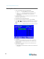
Chapter 9 Managing IBM BladeCenter Servers
141
Refreshing Channel Status........................................................................................................142
Renaming a BladeCenter Chassis.............................................................................................143
Renaming a Blade Server..........................................................................................................144
Chapter 10 Configurations
146
Principles of Re-Connection ......................................................................................................146
Tiered Configurations.................................................................................................................147
Standard Tiered Configurations.......................................................................................147
Non-Standard Tiered Configurations...............................................................................150
Stacked Configurations..............................................................................................................155
Definition of Stacked Configuration .................................................................................155
System Constraints .........................................................................................................155
Standard Stacked Configurations....................................................................................156
vii
Contents
Loop-Back Configuration ...........................................................................................................159
Different Cable Length Configuration ........................................................................................160
P2-HubPac Configuration and Multiple Video ...........................................................................161
Configuration for Multiple Video ......................................................................................161
Chapter 11 User Station Direct Mode
165
Chapter 12 Firmware Upgrade
167
General Update Procedure........................................................................................................167
STEP (A): Download the Latest Firmware and Release notes .......................................167
STEP (B): Establish a Connection between the Device and the PC...............................168
STEP (C): (Optional) Verify the Stacking-Related Configuration ....................................169
STEP (D): Launch the Paragon Update Utility ................................................................169
Failsafe Upgrade Feature ..........................................................................................................170
Main Units........................................................................................................................171
Stacking Units..................................................................................................................172
User Stations ...................................................................................................................175
P2-HubPac Upgrade Operation.................................................................................................176
STEP (A): Get the Latest Firmware, Driver and Release Notes .....................................176
STEP (B): Connect One Cluster of the HubPac to the PC..............................................177
STEP (C): Install the USB-to-RS485 Driver on the PC ...................................................179
STEP (D): Launch the Paragon Update Utility ................................................................183
STEP (E): Repeat Steps (B) and (D) for the Other Clusters ...........................................184
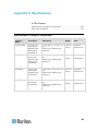
Appendix A Specifications
185
Specifications of Paragon II Components..................................................................................185
Cat5 Cable Guidelines...............................................................................................................189
Appendix B Recommendation for Better Video Quality
191
Deployment Recommendations.................................................................................................191
Supported Resolutions on P2-EUST and P2-EUST/C ..............................................................192
4:3 Aspect Ratio ..............................................................................................................192
16:10 Aspect Ratio ..........................................................................................................192
Appendix C Connecting Serial Devices to a Paragon II System
193
Introduction to Serial CIMs ........................................................................................................193
Installing a Serial CIM ................................................................................................................194
Installing P2CIM-SER or P2CIM-SER-EU.......................................................................194
Installing AUATC .............................................................................................................194
viii
Contents
Operating a Serial CIM ..............................................................................................................196
P2CIM-SER or P2CIM-SER-EU ......................................................................................196
AUATC.............................................................................................................................197
Configuring AUATC .........................................................................................................201
Troubleshooting AUATC..................................................................................................202
Appendix D Other Raritan Components Working with Paragon II
204
Paragon Manager Overview ......................................................................................................204
Installing Paragon Manager.............................................................................................204
Remotely Refreshing IBM BladeCenter Channel Status.................................................205
CommandCenter Secure Gateway Integration..........................................................................205
PCCI Integration ..............................................................................................................205
Dominion KX II Integration...............................................................................................207
Appendix E Integration with Third-Party Switching Devices
210
Using the OmniView Secure KVM Switch .................................................................................210
Special Notice with the P2-EUST/C Card Reader...........................................................212
Supported Keyboards......................................................................................................212
Using the NVISION NV5128 Multi-format Router......................................................................213
STEP (A): Install Appropriate Audio/Video Equipment ...................................................214
STEP (B): Associate Router Ports with Paragon Ports in Paragon Manager .................215
STEP (C): Keep Paragon Manager Running and Connected.........................................216
Illustration: Routing a Server's Audio Signals..................................................................216
Audio/Video Routing Characteristics...............................................................................218
Using the IHSE DDXi Digital KVM Extender .............................................................................219
Using the SMK-LINK RemotePoint Emerald Navigator Remote Control ..................................221
Appendix F Downloading Release 4.4 Firmware
223
Appendix G More Resources or Information
224
Powering-On Sequence of Multi-Tier Configuration ..................................................................224
Quick Reference Chart ..............................................................................................................225
Password .........................................................................................................................225
Hot Key Settings..............................................................................................................225
Autoscan Settings............................................................................................................225
Timeout Settings..............................................................................................................225
Network Settings .............................................................................................................226
Channel Access...............................................................................................................226
Video................................................................................................................................226
Power...............................................................................................................................227
Product Information .........................................................................................................228
Reset ............................................................................................................................... 228
ix
Contents
Troubleshooting .........................................................................................................................228
Paragon II FAQs Online.............................................................................................................230
Index
x
231
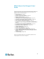
What's New in the Paragon II User
Guide
The following sections have changed or information has been added to the
Paragon II User Guide based on enhancements and changes to the
equipment and/or user documentation.
Product Features (on page 6)
Step (B): Connect User Stations (on page 13)
Step (C): Connect Servers (on page 14)
A KVM System with A Single Paragon Switch (on page 19)
Information about Keyboard, Mouse and Video (on page 45)
How to Connect a USB Combo Keyboard (on page 47)
Sun Keyboard Layout Settings (P2CIM-SUN or P2CIM-ASUN) (on
page 51)
Sun Keyboard Layout Settings (P2ZCIM-SUN) (on page 52)
Non-Standard Tiered Configurations (on page 150)
Triangle Configuration (on page 151)
Dominion KX II Integration (on page 207)
Using the IHSE DDXi Digital KVM Extender (on page 219)
Using the SMK-LINK RemotePoint Emerald Navigator Remote
Control (on page 221)
Troubleshooting (on page 228)
Please see the Release Notes for a more detailed explanation of the
changes applied to this version of Paragon II.
xi
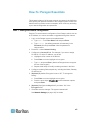
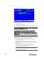
How-To: Paragon Essentials
This chapter includes 10 of the most common use cases to help familiarize
users quickly with practical utilization of the Paragon system. Please note
that this section provides common examples, which could vary according
to your actual configuration and operations.
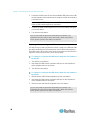
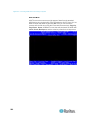
Case 1. Setting the Network Configuration
Purpose: To set the network configuration of the Paragon switch, such as
an IP address, so it can be accessed or upgraded through the network.
1. Log in to the Paragon system as an administrator.
a. Type admin in the User Name field and press Enter.
b. Type raritan (the default password; all lowercase) in the
Password field and press Enter. Note the password is
case-sensitive.
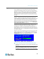
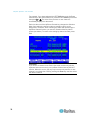
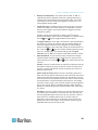
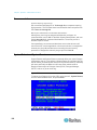
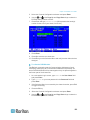
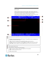
2. Press F5 --> select Network Setting.
3. Configure the Current IP field. For example, if you want to assign
90.180.52.157 as the IP address, you do this:
a. Highlight the first number in the IP field.
b. Press Enter to turn the highlight color to green.
c.
Type 090 and press Enter. (Note that Paragon does not support
the use of the keypad.)
d. Repeat similar steps to modify remaining numbers in this field.
4. Configure remaining fields respectively, including Net Mask, Gateway
IP and Port No.
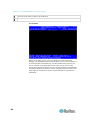
5. (Optional) By default, Encryption is set to “Off.” To change this
setting:
a. Press Enter to turn the highlight color to green.
b. Press the arrow keys ( ,
and press Enter.
,
,
) to switch between options
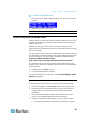
6. (Optional) Configure the Keys field if you select “On” in the
Encryption field.
7. Press S to save the changes. The system restarts itself.
See Network Settings (on page 120) for details.
xii
How-To: Paragon Essentials
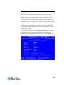
Case 2. Multiple Write Access to the Same Server
Purpose: To enable various users to view the same server simultaneously
and to grant them equal opportunity to compete for the control/operation of
the server when the keyboard/mouse activity in the server has become
inactive for a preset period of time (1 second by default unless it is
customized). Only one person is allowed to control/operate the server at
one time.
1. Log in to the Paragon system as an administrator.
a. Type admin in the User Name field and press Enter.
b. Type raritan (the default password; all lowercase) in the
Password field and press Enter. Note the password is
case-sensitive.
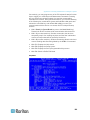
2. Press F5 --> select System Configuration.
3. Press the arrow keys ( ,
field.
,
,
) to highlight the Operation Mode
4. Press Enter to turn the highlight color to green.
5. Press the arrow keys ( ,
and press Enter.
,
,
) to select the option "PC Share"
6. Press S to save the changes.
See System Configuration (on page 100) for details.
Now every user can access the same server simultaneously.
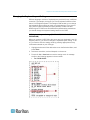
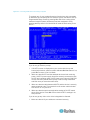
Case 3. Controlling a Device's Power
Purpose: To control the power supply of specific servers, devices or even
Paragon switches as long as they are connected to any power strip in the
Paragon system. These devices can be turned on, turned off or power
cycled as you wish.
1. Log in to the Paragon system as an administrator.
a. Type admin in the User Name field and press Enter.
b. Type raritan (the default password; all lowercase) in the
Password field and press Enter. Note the password is
case-sensitive.
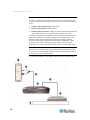
2. Associate the power outlets of the power strip with the connected
devices. For example, if a router receives power from outlet No. 1 of
the power strip, and both of the power strip and router are connected
to the same Paragon switch. The router is named “Router-Win” in the
system. Do the following to associate them.
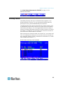
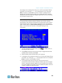
a. Press F5 --> select Channel Configuration.
xiii
How-To: Paragon Essentials
b. Highlight the channel of the power strip. For example, highlight the
channel No. 25 if the power strip is connected to that channel.
c.
Press G to enter the Outlet Configuration screen of the power
strip.
d. Change the type of outlet No. 1: press Enter --> press the arrow
key to select “CPU” --> press Enter.
e. Associate the outlet No. 1 with the router: press the right arrow
key to move the highlight --> press Enter --> highlight the router
name “Router-Win” --> press Enter.
See Associating a Device with a Power Outlet (on page 124)
for details.
f.
Press S to save the power association.
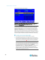
3. Now you can control the power supply to “Router-Win” by doing this:
a. Press F2 to return to the Selection Menu screen.
b. Highlight the channel associated with the power strip. For
example, highlight the channel No. 33 if the router “Router-Win” is
connected to that channel.
c.
Press F3 to view the associated power outlet screen.
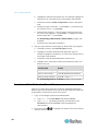
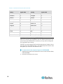
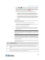
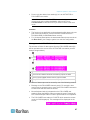
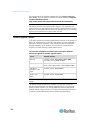
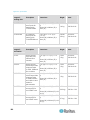
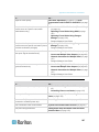
d. Highlight one or more power outlets, and choose the action you
want to carry out:
Desired result
Power off the outlet(s)
Do this
Power on the outlet(s)
Press O (alphabetical character)
Power cycle the outlet(s)
Press R --> type yes
Press X --> type yes
See Controlling Power to an Outlet (on page 125) for details.
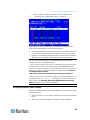
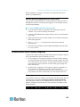
Case 4. Local Video Redirection (Forced Video)
Purpose: To locally direct a server to output its video/keyboard/mouse
data to a specific user station so the user of the specified user station can
be assigned to view and even work on the server.
1. Log in to the Paragon system as an administrator.
a. Type admin in the User Name field and press Enter.
b. Type raritan (the default password; all lowercase) in the
Password field and press Enter. Note the password is
case-sensitive.
2. Press arrow keys ( , ) to highlight the channel of the server whose
data you want to direct.
xiv
How-To: Paragon Essentials
3. Press Tab and the message "Force switch to user port" appears on
the message bar.
4. Type the port number of the desired user station. For example, if you
want to direct the data to the user station connected to the user port
No. 3, type 3 and press Enter.
See Video Redirection (Forced Video) (on page 104) for details.
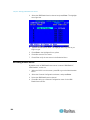
Case 5. Using Multiple Video Ports
Purpose: To have the access to a specific video port automatically trigger
the video outputs of the other video ports on the same server (Paragon is
designed to output a maximum of 16 video ports of a server).
1. Connect four video ports of the server respectively to four channels of
the same Paragon switch via four CIMs. Three of the CIMs must be
P2CIM-AUSB and one could be either P2CIM-AUSB or P2CIM-APS2.
For example, you may connect them to channel port No. 1, 2, 3 and
26.
See Connecting CIMs to a Multi-Channel Video Server (on page
85) for details.
2. The Paragon administrator sets up the channel association group
using Paragon Manager. Do this:
a. Launch Paragon Manager.
b. Connect and log into the Paragon system by doing this: choose
Session > Connect --> choose the Paragon switch you want to
connect --> type the administrator name/password --> click
Login.
c.
Create the association group consisting of channel numbers 1, 2,
3 and 26: choose Set up > Multiple Video > New --> type
necessary data --> select four channels 1, 2, 3 and 26 --> click
OK.
d. Ensure the channel triggering the video outputs of the other
channels is set as the “first” channel. For example, the
administrator may choose 3 in the First Channel field so channel
No. 3 will be the channel which causes the other three channels to
output their video data.
See Channel Association for Multiple Video (on page 107) and
Paragon Manager User Guide for details. This user guide is available
on Raritan website's Firmware and Documentation section
(http://www.raritan.com/support/firmware-and-documentation/).
3. Any user who wants to perform the Multiple Video function logs into
the Paragon system. For example, one user uses the user station
connected to the user port No. 2 to log into the system with the
following user name which has no password required.
xv
How-To: Paragon Essentials
user name: user02
password: <no password>
4. Select the “first” channel of the association group on the On-Screen
User Interface (OSUI). In this example, highlight channel number 3
and press Enter.
5. The other video ports of the same server connected to channel
numbers 1, 2 and 26 automatically output their video data to three
user stations subsequent to the one where user02 is operating, which
are connected to user port No. 3, 4 and 5 respectively.
6. When user02 disconnects the channel number 3 or even logs out of
the system, the three subsequent user stations are also logged off.
See Concurrent Multiple Video Outputs (on page 83) for details.
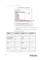
Case 6. Restoring Settings to Factory Defaults
Purpose: To reset the Paragon switch to its factory default settings when
you want to clear customized settings, such as the device name, system
settings, and so on.
1. Log in to the Paragon system as an administrator.
a. Type admin in the User Name field and press Enter.
b. Type raritan (the default password; all lowercase) in the
Password field and press Enter. Note the password is
case-sensitive.
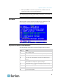
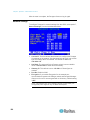
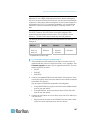
2. Press F5 --> select System Reset Settings.
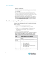
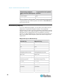
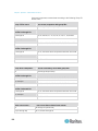
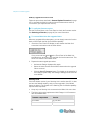
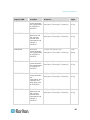
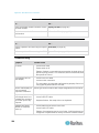
3. Highlight the field(s) that you want to reset, and change the setting to
Yes by doing this: press Enter --> press any arrow key --> press
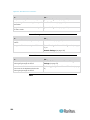
Enter. The affected scope of different fields are described below:
Field
Device Name
Settings returning to factory defaults
The Device ID field in the System Configuration
submenu
Network
Settings
All settings in the Network Setting submenu
User Profiles
All settings of the following submenus or settings:
System
Configuration
xvi
User Configuration
User Station Profile
User Profile settings that are displayed
when pressing F4
All settings in the System Configuration submenu
except for the Device ID field
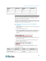
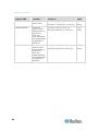
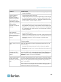
How-To: Paragon Essentials
Field
Channel
Configuration
Settings returning to factory defaults
All settings or records of the active and inactive
channels in the Channel Configuration submenu are
cleared, but the data of active channels is rebuilt
automatically after the reset
4. Now reset the selected items. Press O (alphabetical character) -->
type yes --> press Enter.
5. The system will log out all of logged-in users and return the selected
settings to factory defaults.
See System Reset (on page 119) for details.
Case 7. Using the Integrated Card Reader
Purpose: To pass the login authentication configured in specific servers
that require the input of the data stored in an appropriate smart card. This
function requires the card reader-enabled firmware and devices, including
the Paragon switch with firmware 4.3 or above, P2-EUST/C and
P2CIM-AUSB-C.
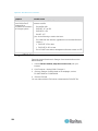
1. Log in to the Paragon system utilizing a user station with an integrated
card reader (P2-EUST/C).
2. Access the server where the appropriate authentication software and
driver have been installed and configured properly and which is
connected to the Paragon system via P2CIM-AUSB-C.
3. When you see the blank screen or a message prompting you to insert
the card, insert your smart card into the card reader of the user station.
4. Depending on the configuration of the target server or authentication
software, you may also need to enter a PIN.
5. After the login authentication and authorization has been completed,
you can start working on the server.
6. When you complete your work, press the hot key (default: Scroll Lock)
twice quickly to trigger the OSUI.
See Using the OSUI for Initial Configuration (on page 36) for
details.
7. Press Shift +F9 to disconnect the server, and then remove the card.
See Using the Card Reader (on page 95) for details.
The card's authentication data is not stored in the Paragon system so you
must repeat Steps 3 to 5 if you want to access the same server again.
xvii
How-To: Paragon Essentials
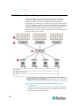
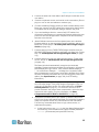
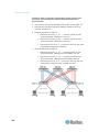
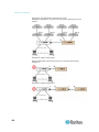
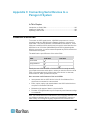
Case 8. Creating Multiple Paths to the Same Server(s)
Purpose: To ensure that there is redundant access to specific servers. In
this example, we will create three available paths for access to specific
servers using the structure of multiple Base Units.
Note: A Base Unit is the “first-tier” Paragon switch.
1. Prepare six Paragon switches, such as P2-UMT1664M and/or
P2-UMT832M.
2. Choose three of them as Base Units, two as the 2nd tier, and one as the
3rd tier. If these switches do not share the same firmware version,
make sure the versions of lower tiers are later than those of upper tiers.
For example, Base Unit is with firmware version 4.2 and 2nd Tier with
version 4.0.
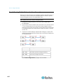
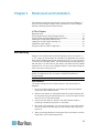
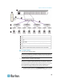
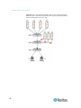
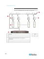
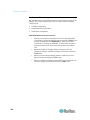
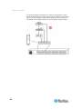
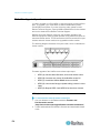
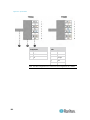
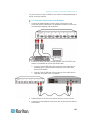
3. Connect all of these Paragon switches with Category 5 (Cat5) UTP
cables from the channel ports of lower tiers to user ports of upper tiers
as illustrated below:
C
Channel ports
U
User ports
1(A) ~ 1(C)
Base Units (first-tier Paragon switches)
2(A) ~ 2(B)
Second-tier Paragon switches
3(A)
Third-tier Paragon switch
See Tiered Configurations (on page 147) for details.
xviii
How-To: Paragon Essentials
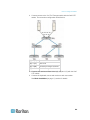
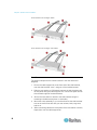
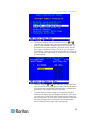
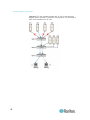
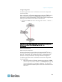
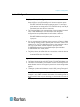
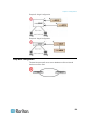
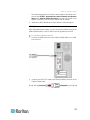
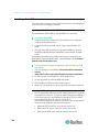
4. Connect servers to the “3rd Tier” Paragon switch with the Cat5 UTP
cables. The connection configuration looks like this:
S(1) ~ S(X)
Servers
1(A) ~ 1(C)
Base Units
2(A) ~ 2(B)
Second-tier Paragon switches
3(A)
Third-tier Paragon switch
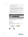
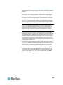
5. Connect user stations to Base Units 1(A), 1(B) and 1(C) with the Cat5
UTP cables.
6. Connect the keyboard, mouse and monitor to each user station.
See Basic Installation (on page 11) section for details.
xix
How-To: Paragon Essentials
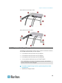
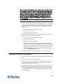
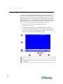
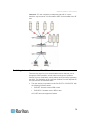
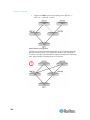
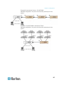
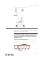
7. Now three different paths (blue solid lines as illustrated below) are
available for users to access any servers connected to the “3rd Tier.”
See Configurations (on page 146) for more details.
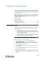
Case 9. Upgrading the Firmware of Paragon Switches
Purpose: To upgrade Paragon II switches and benefit from recent
enhancements to the Paragon product line. (Please note the description
herein refers to regular firmware upgrade and does not apply to “special”
firmware upgrade which involves the boot loader or failsafe feature.)
1. Verify that the Main Switching Unit (Main Unit) is connected to the
network, and relevant network settings, such as the IP address, are
configured properly.
See Case 1. Setting the Network Configuration (on page xii) for
details.
2. (Optional) If there has been any Stacking Unit connected to the Main
Unit, keep them attached and turned on. For example, you may
upgrade one P2-UMT832M (Main Unit) and three P2-UMT832S
(Stacking Units) which are connected to it altogether. Also verify the
following Stacking-related settings:
The “Stacking Support” setting in the Main Unit is appropriate.
The value of the “Set Stack ID” setting in every connected
Stacking Unit is unique.
See General Update Procedure (on page 167) for details.
xx
How-To: Paragon Essentials
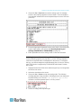
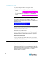
3. Download the firmware from the Raritan website
(http://www.raritan.com): click Support > Firmware and
Documentation > Paragon II, and click the latest version to start the
download.
4. Unzip the downloaded file. Among the unzipped files, there are a file
named ParagonUpdate_xxx.exe and a firmware file named
P2-xxx.hex (xxx represents the version). For example, the firmware
file for version 4.2 is named P2-3E5.hex.
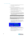
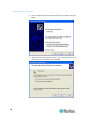
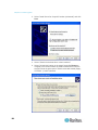
5. Double click “ParagonUpdate_xxx.exe” to execute the program.
6. Enter the information of the Main Unit in the Paragon Update utility.
For example:
In the Name column, type Paragon832M
In the IP address/Serial column, type 90.180.52.157
In the Port column, type 3000
If you have assigned the Encryption keys in the Paragon system,
remember to type the same encryption data in the Encryption
Key column
See Paragon Manager User Guide for details. This user guide is
available on Raritan website's Firmware and Documentation
section
(http://www.raritan.com/support/firmware-and-documentation/).
7. Ensure the checkbox before the Main Unit is selected ( ).
8. Click Load Hex File to select the firmware file “P2-xxx.hex”. For
example, choose the file “P2-3E5.hex”to upgrade to firmware version
4.2.
9. Click Send To Paragon --> Yes. Then the utility starts to upgrade the
Main Unit and every connected Stacking Unit (if any).
10. Once all of the upgrade is completed, a message appears.
Case 10. Upgrading the Firmware of User Stations
Purpose: To upgrade the user stations and benefit from recent
enhancements to the Paragon product line.
1. Connect the user station to the serial port (e.g. COM 2) of a computer
via an RS-232 male-to-female serial cable shipped with the user
station.
2. Download the firmware from the Raritan website
(http://www.raritan.com): click Support > Firmware and
Documentation > Paragon II, and click the latest version to start the
download.
xxi
How-To: Paragon Essentials
3. Unzip the downloaded file. There are a file named
ParagonUpdate_xxx.exe (xxx represents the version) and a firmware
file for the user station. If using the P2-EUST, the firmware file is
named EUST-xxx.hex. If using the P2-UST, the firmware file is named
V5-xxx.hex (xxx represents the version).
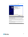
4. Double click “ParagonUpdate_xxx.exe” to execute the program.
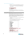
5. Enter the information about the user station in the Paragon Update
utility. For example:
In the Name column, type P2-EUST-1
In the IP address/Serial column, select <Default Serial>
In the Port column, type 2. This represents the serial port—COM2
6. Ensure the checkbox before the user station is selected ( ).
7. Click Load Hex File to select the firmware file.
8. To start the upgrade, click Send To Paragon --> Yes.
9. Once the upgrade is completed, a message appears.
See General Update Procedure (on page 167) and Paragon
Manager User Guide for details. This user guide is available on
Raritan website's Firmware and Documentation section
(http://www.raritan.com/support/firmware-and-documentation/).
xxii
Chapter 1
Introduction
Thank you for purchasing Raritan's Paragon II. The Paragon family is
about breaking away from the traditional, expensive model of server
management—one server, one dedicated monitor, one dedicated
keyboard. Paragon enables one or more workstations to access multiple
servers—even servers of different platforms.
No matter how large or small your setup, no matter how simple or how
complex, Raritan is confident that there is a Paragon system just right for
you.
In This Chapter
Paragon II Overview ..................................................................................1
Product Photos ..........................................................................................5
Product Features .......................................................................................6
Package Contents ...................................................................................10
Paragon II Overview
The Paragon II is designed to perform heavy-duty
multiple-user-to-many-server keyboard/video/mouse (KVM) matrix
switching without burdening you with big, confusing hydra-headed cables.
Instead, the Paragon II uses standard Category 5 (Cat5) unshielded
twisted-pair (UTP) cabling, like the type that is already installed at many
sites. It can connect users with servers across as much as 1000 feet (304
m) of such cabling.
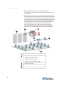
A Paragon II system consists of several components:
Main Switching Units serve as Base Units and matrix switches,
securely connecting users to servers.
Note: For documentation purpose, Main Switching Units are hereafter
called Main Units in this manual.
Stacking Units connect to Main Units and enable you to expand your
system in a space-saving manner without sacrificing channels.
Computer-Interface Modules (CIMs) are connected to each server.
User Stations connect your keyboard, monitor, and mouse to the
Main Unit and provide an intuitive On-Screen User Interface (OSUI)
for accessing attached servers.
Different models of user stations are explained below:
Standard User Station (P2-UST) provides basic user station
functions as described above.
Enhanced User Station (P2-EUST) provides the P2-UST features,
plus superior video quality with automatic skew compensation.
1
Chapter 1: Introduction
Enhanced User Station with an integrated card reader
(P2-EUST/C) functions similar to a P2-EUST, and enables card
authentication.
IP-Enabled User Stations, including P2-USTIP1 and P2-USTIP2,
one- and two-worker user stations, have integrated IP access and
provide KVM over IP capability for anytime, anywhere access and
control of servers. Key features include a slim design and GUI for
point-and-click remote access. The P2-USTIP series supports IP
access, enabling one or two remote users to access Paragon
II-connected servers from anywhere via a Web browser.
P2-USTIP2 also supports 128-bit SSL encryption and local
authentication through Paragon II, or centralized authentication
when used with Raritan's CommandCenter Secure Gateway.
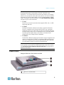
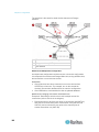
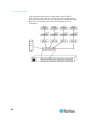
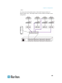
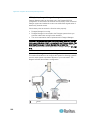
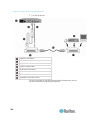
128 servers
Single base plus stacking unit
A: Paragon II Stacking cable(s)
B: Standard Cat5 UTP cable
C: Computer Interface Module (CIM)
IP-enabled user station
Remote user
15 user stations
2
Chapter 1: Introduction
Main Units
There are a number of Main Units that support a wide range of
configurations:
P2-UMT242 supports 2 users and 42 servers
P2-UMT442 supports 4 users and 42 servers
P2-UMT832M supports 8 users and 32 servers
P2-UMT1664M supports 16 users and 64 servers
CIMs
There are also several different CIMs for different types of servers (all
must output VGA video):
P2CIM-APS2:
Supports servers with IBM PS/2-type keyboard and mouse ports
Provides automatic skew compensation when working with
P2-EUST or P2-EUST/C
Works with P2-HubPac in PC, MAC, and Sun USB configurations
P2CIM-ASUN:
Supports servers with Sun-type keyboard and mouse ports
Provides automatic skew compensation when working with
P2-EUST or P2-EUST/C
Works with P2-HubPac in PC, MAC, and Sun USB configurations
P2CIM-AUSB:
Supports servers with USB- or Sun USB-type keyboard and
mouse ports
Provides automatic skew compensation when working with
P2-EUST or P2-EUST/C
Works with P2-HubPac in PC, MAC, and Sun USB configurations
P2CIM-AUSB-C
Provides all of the functions of P2CIM-AUSB
Enables smart card access when communicating with P2-EUST/C
P2ZCIM-PS2
Supports servers with IBM PS/2-type keyboard and mouse ports
Provides an extra RJ45 port to support a “local server” installed
between a user station and a Paragon Base Unit, as well as
chaining of Z-CIMs for clustered access
P2ZCIM-USB
Supports servers with USB-type keyboard and mouse ports
3
Chapter 1: Introduction
P2CIM-SER, P2CIM-SER-EU and AUATC
Provides an extra RJ45 port for chaining of Z-CIMs for clustered
access
Support servers or ASCII serial devices connected to the Paragon
II system through their RS-232 serial ports
P2CIM-APS2DUAL
Supports servers with IBM PS/2-type keyboard and mouse ports
Doubles the number of users that have access to a particular
server
Provides automatic skew compensation when working with
P2-EUST or P2-EUST/C
P2CIM-AUSBDUAL
Supports servers with USB- or Sun USB-type keyboard and
mouse ports
Doubles the number of users that have access to a particular
server
Provides automatic skew compensation when working with
P2-EUST or P2-EUST/C
P2CIM-APS2-B
Supports IBM BladeCenter® (blade servers) with IBM PS/2-type
keyboard and mouse ports
Provides automatic skew compensation when working with
P2-EUST or P2-EUST/C
P2CIM-AUSB-B
Supports IBM BladeCenter® (blade servers) with USB-type
keyboard and mouse ports
Provides automatic skew compensation when working with
P2-EUST or P2-EUST/C
Important: As of release 4.4.1, Paragon II no longer supports Paragon I
Z-CIMs, including the UKVMSPD, which supports local PC mode.
Therefore, to ensure your system continues working with these first
generation Z-CIMs, do NOT upgrade it to 4.4.1 or later. If a downgrade to
4.4 is needed, you can download prior firmware releases from the Raritan
website (http://www.raritan.com). For details, see Downloading Release
4.4 Firmware (on page 223).
4
Chapter 1: Introduction
User Stations
There are three types of user stations: P2-UST, P2-EUST, and
P2-EUST/C. You usually should connect the user stations to a Paragon
switch, but if you want to connect the user station to one server across a
long stretch of Cat5 or higher cable, run such a cable between a “direct
mode” user station and a P2CIM-APS2. See User Station Direct Mode
(on page 165) for more information.
P2-UST
P2-UST is a universal user station that supports PS/2, Sun, or USB
keyboards and mice.
P2-EUST
P2-EUST is Raritan's enhanced user station, which functions like
P2-UST. In addition to the functions that P2-UST has, it provides
enhanced control over video quality by either automatically adjusting
the skew delay of each color, or allowing the user to manually adjust
the video gain and skew delay on the screen, and store these
preferences in the Paragon switch's database.
P2-EUST/C
P2-EUST/C is Raritan's enhanced user station with an integrated card
reader. It functions like P2-EUST, but supports USB keyboards and
mice only. In addition to the functions that P2-EUST has, it provides
the card reader function for smart card authentication.
Note: We recommend using a Sun keyboard if there are any Sun servers
in your system. If you must use a PS/2 keyboard to control Sun servers,
see Information about Keyboard, Mouse and Video (on page 45) for
additional information.
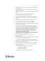
Product Photos
Paragon II Main Unit, User Station and CIM
Main Unit: P2-UMT832M
5
Chapter 1: Introduction
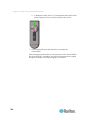
User Station: P2-EUST
CIM: P2CIM-APS2
P2-EUST/C (Front and Rear Sides)
Product Features
6
2U design supports 16 users, 64 servers (model: P2-UMT1664M)
1U design supports 8 users, 32 servers (model: P2-UMT832M)
1U design supports 4 users, 42 servers (model: P2-UMT442)
1U design supports 2 users, 42 servers (model: P2-UMT242)
Expands the number of users with Raritan's P2CIM-APS2DUAL,
P2CIM-AUSBDUAL, or P2-HubPac
Locates users and servers up to 1000 feet (304 m) apart
Supports 4:3 ratio resolutions up to 1920 x 1440
Supports 16:10 widescreen resolutions up to 1680 x 1050
Supports up to 512 customized user profiles (with optional Memory
Card)
Supports servers running the following operating systems:
Windows® operating systems, incuding Windows® 98, Windows®
2000, Windows® XP, Windows® XP 64-bit, Windows Server™ 2003,
Windows Server™ 2003 64-bit, Windows Server™ 2008, Windows
Server™ 2008 64-bit, Windows Vista®, Windows® 7, Windows® 7
64-bit
Linux operating systems, such as RedHat Enterprise Linux 5,
CentOS 5, and Ubuntu 7 to 10
Apple® Mac operating systems
Sun operating systems
Chapter 1: Introduction
Adds remote access over IP or modem with Raritan's IP-Reach and
UST-IP models
Expands to 10,000 servers via multi-dimensional expansion (with
optional Memory Card)
Stacking switches provide 100% non-blocked expansion with a single
cable
19" rackmount brackets included with Paragon II switch
Simple plug-and-play auto-configure installation
Hot-swappable components with no impact on server operation
Platform-specific CIMs for PS/2, Sun, USB, Sun USB, ASCII/serial
devices
Powerful, intuitive onscreen user interface for simple operation
Flexible, multi-level security for authorized server access
Three system operation modes—private, public, and share
Quick access to previous or next available channels with the Up/Down
Channel hot key combination
Flash firmware upgrades with Failsafe capability via network port
Paragon Manager, a Windows application, provides streamlined
administration of Paragon II infrastructure, including adding, deleting
or modifying user profiles, event logging, and user profile
backup/restore. See Paragon Manager User Guide for additional
information. This user guide is available on Raritan website's
Firmware and Documentation section
(http://www.raritan.com/support/firmware-and-documentation/).
Administrative control of connected users
Turn on, off, or reboot power to any connected device
Network admin port
Supports the connection and control of Raritan power strips, including
8-, 12-, 16-, 20- and 24-outlet power strips.
Power control permissions may be set on a per-outlet basis
Supports the use of Pinnacle FastAction keyboard (when used with
P2CIM-APS2 or P2CIM-APS2DUAL)
Supports 10-BaseT, half duplex network speed (not configurable)
Supports IBM BladeCenter® servers. The following BladeCenter
systems are supported:
BladeCenter E (also referred to as model 8677)
With MM model 48P7055
With AMM model 25R5778
BladeCenter H (also referred to as model 8852)
7
Chapter 1: Introduction
With AMM model 25R5778
Note: IBM has updated the BladeCenter frequently since its original
release. For best results, please use P2CIM-AUSB-B firmware level
0A8 or later. or P2CIM-APS2-B firmware level 0A3 or later.
Supports the use of a 121-key Cortron rugged keyboard at the local
site when used with the following Paragon II user station:
P2-EUST or P2-EUST/C with firmware version 3E46 or later
P2-USTIP with firmware 4.5.0.5.12 or later (local PS/2 port only)
Both PS/2 (part number 536-0062) and USB keyboards (part number
524-0079) are supported. Those with built-in Sun keys are also
supported, and the Sun power key may be used to turn off the server,
but not turn it on.
Supports the use of a Kensington Expert Mouse® and Turbo Mouse
trackball (Model #: 64210) at the local site when used with the
following Paragon II components:
User station: P2-UST, P2-EUST or P2-EUST/C
CIM: P2CIM-AUSB, P2CIM-AUSBDUAL or P2CIM-AUSB-C with
the latest CIM firmware
Supports Multiple Video, also known as “Port-Following Switch.”
Multiple Video enables:
Up to 16 user stations to simultaneously view the video output of a
server that has multiple video outputs.
Up to 16 servers to simultaneously output their video data
Note: The 16-channel video output is available on P2-UMT1664M
models only as of release 4.7, and it is required to use Paragon
Manager 2.0.4 or later.
8
Supports video redirection to a specific user station (known as
“Forced Video”)
Local control by the administrator
Remote control by the administrator and authorized users through
Paragon Manager
Supports authentication with an appropriate smart card when using
Paragon II reader-enabled components:
P2-EUST/C
P2CIM-AUSB-C
Chapter 1: Introduction
Supports using Belkin® OmniView® Secure KVM Switch or Raritan
Dominion® KX II as the front end of the Paragon system
Supports multiple audio/video routing through the integration with the
NVISION® NV5128 router
Supports the use of an IHSE DDXi K443-2U digital KVM extender,
which can locate the user and user station up to 4921 feet (1500 m)
apart
Supports the use of the SMK-LINK RemotePoint Emerald Navigator
laser pointer and presentation tool to remotely control the Paragon II
OSUI at a distance up to 100 feet with the P2-EUST user station
Remote control's model number: VP4450
Receiver's model number: VP6496R
Special Notes:
(1) P2-EUST/C supports Windows, Linux, Mac, and Sun operating
systems, but its integrated card reader supports Windows (including
Windows Server 2008) and Linux operating systems only.
(2) Paragon II releases 4.2 and 4.3 are not compatible with the Paragon II
System Controller (P2SC). They are considered "standalone" releases
and are not supported for installation in a Raritan PCCI environment. As of
release 4.3.1, Paragon II returned to compatibility with P2SC. Existing
Paragon II System Controller customers may upgrade their Paragon II
components to 4.3.1 or higher to benefit from recently added features and
maintenance fixes. Please see the Paragon II 4.3.1 release notes for
minimum firmware levels.
(3) P2-EUST no longer supports the Sun dim8 keyboard as of release 4.8,
but still supports the Sun USB keyboard. If a Sun dim8 keyboard must be
used, downgrade your P2-EUST user stations to 3F5.
9
Chapter 1: Introduction
Package Contents
Paragon Main Unit (P2-UMT242, P2-UMT442, P2-UMT832M, or
P2-UMT1664M):
Main Unit x 1
20-ft. (6.1-m) Cat5 test cable x 2
6-ft. (1.8-m) AC power cord x 1
Rackmount kit x 1 (including brackets and associated screws)
Quick Setup Guide x 1
Paragon Stacking Unit:
Stacking Unit x 1
RUMT-1U-LM304 or RUMT-2U-LM304 rackmount kit x 1
6" stacking cable(s)--the number of cables vary depending on the
model you purchased
P2-UMT832S: Stacking cable x 1
P2-UMT1664S: Stacking cable x 2
AC power cord x 1
Paragon user station (P2-UST, P2-EUST or P2-EUST/C):
User-station module x 1
6-ft. (1.8-m) AC power cord x 1
6-ft. (1.8-m) AC power-extension cord for the connected monitor x 1
16.4-ft. (5-m) DB9 male-to-female serial administration cable x 1
Paragon IP-enabled user station (P2-USTIP1/2):
10
IP-enabled user-station module x 1
6-ft. (1.8-m) AC power cord x 1
16.4-ft. (5-m) DB9 male-to-female serial administration cable x 1
Chapter 2
Quick Start
The Paragon switch and all devices you want to connect to it must
be unplugged and turned OFF prior to installation.
In This Chapter
Basic Installation......................................................................................11
Initial Verification .....................................................................................15
Basic Installation
Ensure that you have turned OFF all servers and Paragon II devices prior
to installation. Installing a basic Paragon II system involves these steps.
Step (A): Connect Stacking Units to a Main Unit (Optional)
Step (B): Connect User Stations to the Main Unit
Step (C): Connect Servers to Paragon II Main and Stacking
Units
Note: Users and servers can be located up to 1000 feet (304 m) apart.
However, try to limit the cable length between the CIM and Paragon II
switch to less than 100 feet (30.5 m) for optimal video quality, and if
possible, limit the total cable length between the user and target server to
less than 500 feet (152 m) for good video quality.
Step (A): Connect Stacking Units
If your Main Unit supports the use of Stacking Units, such as
P2-UMT832M, you can connect compatible Stacking Units to expand the
number of channel ports in the system.
To connect one or more Stacking Units
1. Connect the power cord to the Main Unit.
2. Connect the power cord to the Stacking Unit.
3. Depending on the Stacking Unit you purchased, use one or two
stacking cables to connect the Stacking Unit to the Main Unit.
a. For connecting P2-UMT832S to P2-UMT832M:
11
Chapter 2: Quick Start
Plug one end of a stacking cable into the port—Expansion Port
Out—on the Stacking Unit.
Plug the other end of the cable into the port—Expansion
Port—on the Main Unit.
b. For connecting P2-UMT1664S to P2-UMT1664M:
Plug one end of the stacking cable into "Expansion Port Out A"
on the Stacking Unit and the other end of the cable into the
lower "Expansion Port In" on the Main Unit.
Plug one end of the other stacking cable into "Expansion Port
Out B" on the Stacking Unit and the other end of the cable into
the upper "Expansion Port In" on the Main Unit.
4. (Optional) You can cascade up to three P2-UMT832S Stacking Units
for a P2-UMT832M Main Unit. To add more Stacking Units, follow this
procedure:
a. Plug one end of a stacking cable into the port—Expansion Port
In—on the last Stacking Unit connected to the Main Unit.
b. Plug the other end of the cable into the port—Expansion Port
Out—on the newly added Stacking Unit.
c.
Connect a power cord to the newly added Stacking Unit.
d. Repeat Steps a to c if you want to add one more Stacking Unit.
5. Turn on all Paragon II devices.
6. Set the total number of connected Stacking Units on the front panel of
the Main Unit.
a. Press the FUNC button to activate the Function Menu.
b. Press the
c.
and
buttons to select "Stacking Support."
Press the ENT button to confirm your selection.
d. Press the and buttons to select the total number of Stacking
Units—3 maximum for P2-UMT832M or 1 maximum for
P2-UMT1664M.
e. Press the ENT button to save the setting.
7. Set a unique Stacking Unit ID on the front panel of each Stacking Unit.
12
Chapter 2: Quick Start
a. Press the FUNC button to activate the Function Menu.
b. Press the
c.
and
buttons to select "Set Stack ID."
Press the ENT button to confirm your selection.
d. Press the and buttons to assign the numeric ID. The
guideline of ID assignment is:
Assign 1 as the ID for the first Stacking Unit, which is directly
connected the Main Unit.
Assign 2 as the ID for the second Stacking Unit, which is
connected to the first Stacking Unit.
Assign 3 as the ID for the third Stacking Unit, which is
connected to the second Stacking Unit.
e. Press the ENT button to save the setting.
8. Turn OFF all Paragon II devices.
9. Turn on the Stacking Unit first. If there are multiple Stacking Units, turn
on the Stacking Units from the last one to the first one in sequence.
10. Turn on the Main Unit.
Step (B): Connect User Stations
To connect one or more user stations
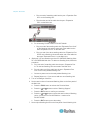
1. Connect a user station to the Main Unit.
a. Plug one end of a Cat5 UTP cable into User Port number 1 on the
back of the Main Unit.
b. Plug the other end of the cable into the RJ45 port on the back of
the user station.
2. Connect a power cord to the user station and turn it on.
13
Chapter 2: Quick Start
3. Connect a PS/2 or USB keyboard, mouse, and a VGA monitor to the
user station. Both wired and wireless keyboards and mice are
supported as of release 4.8.
Note 1: P2-EUST/C provides USB ports only for keyboard and mouse.
Note 2: P2-EUST no longer supports the Sun dim8 keyboard as of
release 4.8, but still supports the Sun USB keyboard. If a Sun dim8
keyboard must be used, downgrade your P2-EUST user stations to
3F5.
4. Turn on the monitor.
5. Repeat Steps 1 to 4 for all other user stations you want to connect to
remaining User Ports.
The user station does not support the use of a VGA-to-DVI converter.
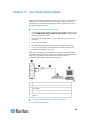
Step (C): Connect Servers
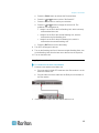
To connect one or more servers
1. Connect a Paragon II CIM to the Main or Stacking Unit.
a. Plug one end of a Cat5 UTP cable into Channel Port number 1 on
the back of the Main Unit or any connected Stacking Unit.
b. Plug the other end of the cable into the RJ45 port of the CIM.
14
Chapter 2: Quick Start
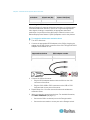
2. Depending on the CIM model you purchased, plug the connectors of
the CIM into a server's PS/2 or USB keyboard, mouse, and VGA ports.
Tip: If the server provides a DVI connector instead of a VGA port,
Raritan recommends using a Raritan or Smart View DVI-to-VGA
converter to connect the CIM. Raritan's ADVI-VGA converter is a DVI
male to VGA female converter, which supports both analog and
integrated (digital and analog) signals. The Smart View DV-101
converter is a DVI female to VGA female converter, which supports
digital signals only. Note that only these two converters have been
tested and are officially supported by Raritan for use with Paragon II.
3. Turn on the server.
4. Repeat Steps 1 to 3 for all other servers you want to connect to
remaining Channel Ports.
Initial Verification
To verify that the server connected to the Paragon system can
be operated:
1. Turn on all devices in the Paragon II system.
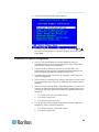
2. The Login screen of the On-Screen User Interface (OSUI) is displayed
on the monitor connected to the user station.
3. Type your user name and password in the appropriate fields and
press Enter. For example, if you are the administrator:
a. Type admin in the User Name field and press Enter.
15
Chapter 2: Quick Start
b. Type raritan (the default password; all lowercase) in the
Password field and press Enter. Note the password is
case-sensitive.
Tip: You can also type any user name for regular users. The
factory-default user names for regular users are user01 through up to
user15, depending on the model of your Main Unit. By default, there
are no passwords for these user names.
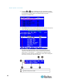
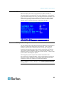
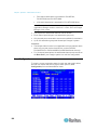
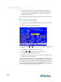
4. The Selection Menu appears.
Channels connecting to servers appear in green. At first there are no
names for any servers so all Name fields are blank.
Note: The only exception is IBM BladeCenter chassis. Paragon II
shows a default name “IBM-Blade” for the device.
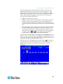
5. Press or on the keyboard to move the highlight to one of the
green channels and press Enter.
6. Now you can view and control the chosen server with the keyboard
and mouse.
7. Press the Scroll Lock key twice QUICKLY to activate the OSUI, and
do one of the following:
16
To choose another green channel for verification, repeat Step 5.
To log out of the system, press F9.
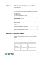
Chapter 3
Rackmount and Installation
This chapter includes full instructions for how to rack-mount Paragon II
devices, install a single Paragon switch, cascades of multiple Paragon
switches, Stacking Units and other devices.
In This Chapter
Rack-Mounting ........................................................................................17
A KVM System with A Single Paragon Switch ........................................19
A KVM System with Cascaded Paragon Switches .................................24
Installing a P2-UMT832S Stacking Unit ..................................................29
Installing a P2-UMT1664S Stacking Unit ................................................30
Installation of the HubPac........................................................................31
Using the OSUI for Initial Configuration ..................................................36
Rack-Mounting
Paragon II user stations and most KVM switches can be mounted in 1U
(1.75", 4.4 cm) of vertical space in a standard 19" equipment rack, except
that P2-UMT1664M switch shall be mounted in 2U (3.5", 8.9 cm) of space.
To rack-mount a Paragon switch, use the brackets and screws that came
with the device. To rack-mount a user station, use Raritan's RUST-LM304
rackmount kit. You can mount a Paragon switch or user station facing the
front of the rack or facing the rear.
Note: If you lose or damage a switch's brackets, replace them with the
RUMT-1U-LM304 kit for any 1U switch or RUMT-2U-LM304 for a
P2-UMT1664M.
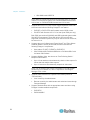
Forward Mount
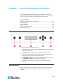
The steps correspond to the numbers shown in the front rackmount
diagrams.
1. Secure the cable-support bar to the back end of the side brackets
using two of the included screws.
2. Slide the user station or KVM switch between the side brackets, with
its rear panel facing the cable-support bar, until its front panel is flush
with the “ears” of the side brackets.
3. Secure the user station or switch to the side brackets using the
remaining included screws (three on each side).
4. Mount the entire assembly in your rack and secure the side brackets'
ears to the rack's front rails with your own screws, bolts, cage nuts,
and so on.
5. When connecting cables to the rear panel of the user station or switch,
drape them over the cable-support bar.
17
Chapter 3: Rackmount and Installation
Front rackmount of a Paragon switch
Front rackmount of a Paragon user station
Rear Mount
The steps correspond to the numbers shown in the rear rackmount
diagrams.
1. Secure the cable-support bar to the front end of the side brackets,
near the side brackets' “ears,” using two of the included screws.
2. Slide the user station or KVM switch between the side brackets, with
its rear panel facing the cable-support bar, until its front panel is flush
with the back edges of the side brackets.
3. Secure the user station or switch to the side brackets using the
remaining included screws (three on each side).
4. Mount the entire assembly in your rack and secure the side brackets'
ears to the rack's front rails with your own screws, bolts, cage nuts,
and so on.
5. When connecting cables to the rear panel of the user station or switch,
drape them over the cable-support bar.
18
Chapter 3: Rackmount and Installation
Rear rackmount of a Paragon switch
Rear rackmount of a user station
A KVM System with A Single Paragon Switch
If installing a single Paragon switch, keep in mind the maximum numbers
of user stations and servers you can connect:
2 user stations and 42 servers to a P2-UMT242
4 user stations and 42 servers to a P2-UMT442
8 user stations and 32 servers to a P2-UMT832M
16 user stations and 64 servers to a P2-UMT1664M
Prior to installation, all Paragon components, servers, and monitors
must be turned OFF and unplugged.
To install a single-Paragon-switch system and perform initial
configuration
1. Initialize the Paragon switch.
19
Chapter 3: Rackmount and Installation
a. Connect the switch's included power cord from the IEC 320 inlet
on its rear panel to an appropriate AC outlet.
b. Turn on the switch.
2. Connect a user station and its attached devices.
a. Connect one end of a Cat5 UTP cable to user port # 1 on the back
of the switch. Connect the other end of the cable to the RJ45 Cat5
port on the back of the user station.
b. Connect the user station's included power cord from the IEC 320
inlet on its rear panel to an appropriate AC outlet.
c.
Turn ON the user station. It will power up and establish
communication with the Paragon switch.
d. Connect a keyboard, a mouse, and a monitor to the user station.
Both wired and wireless keyboards and mice are supported as of
release 4.8. (To control Sun servers with a PS/2 keyboard, please
see Information about Keyboard, Mouse and Video (on page
45) for additional information.)
Note: P2-EUST no longer supports the Sun dim8 keyboard as of
release 4.8, but still supports the Sun USB keyboard. If a Sun dim8
keyboard must be used, downgrade your P2-EUST user stations to
3F5.
e. Plug in and turn on the monitor.
3. Perform initial configuration of the user station.
a. The Login screen should appear on the user station’s attached
monitor. If the Scroll Lock LED on the user station’s attached
keyboard is blinking, the Paragon is ready to accept function key
commands, which allow users to login, select servers, or
administer the system.
If the monitor instead displays a “.....No connection to Paragon.....”
message, the user station is not properly connected to the
Paragon switch. Check for loose connections and make sure you
are using good, intact Cat5 cables.
b. Type admin in the User Name field and press Enter. In the
Password field, type the default password raritan (all
lowercase) and press Enter.
20
Chapter 3: Rackmount and Installation
c.
The OSUI Selection Menu appears, indicating that the user
station is correctly installed.
4. Repeat steps 2 and 3 for each user station you want to connect to the
Paragon switch.
5. Connect a CIM and the desired server.
a. Connect the cable strands of an appropriate CIM to the
appropriate ports on a server:
P2CIM-APS2 (PS/2 compatible servers) or P2CIM-APS2-B
(IBM BladeCenter Management Module with PS/2 ports):
Plug the HD15 strand into the server’s HD15 VGA video port. Plug
the purple 6-pin mini-DIN keyboard strand into the server’s 6-pin
mini-DIN keyboard port. Plug the light green 6-pin mini-DIN strand
into the server’s 6-pin mini-DIN mouse port.
P2CIM-ASUN (Sun compatible servers):
Plug the HD15 strand into the server’s HD15 VGA video port. Plug
the 8-pin mini-DIN strand into the server’s 8-pin mini-DIN
keyboard/mouse port.
P2CIM-AUSB, P2CIM-AUSB-C (USB compatible servers), or
P2CIM-AUSB-B (IBM BladeCenter Management Module with
USB ports):
Plug the HD15 strand into the server’s HD15 VGA video port. Plug
the USB Type A strand into one of the server’s USB Type A ports.
P2CIM-APS2DUAL (PS/2 compatible servers):
Connect keyboard, monitor, and mouse cables attached to the
CIM to the appropriate 15-pin female video port and 6-pin
mini-DIN mouse and keyboard ports on the server.
21
Chapter 3: Rackmount and Installation
P2CIM-SER, P2CIM-SER-EU and AUATC (serial servers,
routers, and so on):
Please see Connecting Serial Devices to Paragon II System
(see "Connecting Serial Devices to a Paragon II System" on
page 193) for installation instructions.
P2ZCIM and Z-CIM (local single-user IBM PS/2 compatible
servers):
Please see Paragon II and P2ZCIMs (see "P2ZCIMs and
Z-CIMs" on page 128) for installation instructions.
b. Plug in and turn on the server. If the CIM is installed and operating
properly, the CIM’s green LED will start blinking: once per second
while the CIM is idle, more quickly while data is transmitted in
either direction.
c.
Connect one end of a Cat5 UTP cable to channel port #1 on the
back of the Paragon switch. Connect the other end of the cable to
the RJ45 port on the CIM.
6. Configure the CIM and the attached server.
a. The monitor attached to the user station will display the Selection
Menu; with the server you just connected displayed in green. Use
the and keys to move the highlight to that entry and press
Enter. If you can access and operate the server normally, the CIM
is connected successfully. Raritan recommends you give the
server a meaningful system name at this time, as described in the
next steps.
Note: If your video image is fuzzy, you can adjust the video gain to
focus the video image. Fuzzy video images may happen if you are
using an LCD flat-panel monitor. For more information, see Video
Gain Adjustment (on page 61). The P2-EUST and P2 EUST/C
provide automatic and manual skew compensation, which also help
improve the video quality. For more information, see Skew
Compensation with P2-EUST or P2-EUST/C (on page 62).
22
Chapter 3: Rackmount and Installation
b. Press F5 to activate the Administration Menu. Use the and
keys to move the highlight to the Channel Configuration entry and
press Enter.
c.
The Channel Configuration submenu appears. Use the and
keys or Tab to move the yellow highlight to the Name field for the
channel port number where you installed the server and press
Enter. The highlight turns light blue.
d. Edit the name (the highlight turns green when you start typing).
Press Enter when finished, and press S to save the new name.
e. Press F2 to return to the Selection Menu. Verify that the new
name appears in the Selection Menu.
7. Repeat Steps 5 and 6 for each CIM and server you want to connect to
the Paragon switch’s channel ports.
23
Chapter 3: Rackmount and Installation
A KVM System with Cascaded Paragon Switches
Paragon II's channel port capacity can be expanded by installing a
cascade of Paragon matrix switches (Main Units). In a "two-tiered"
cascaded system, one or more subsidiary Paragon switches are
connected to the channel ports of a Base Unit ("first-tier" Paragon switch).
If you fully populate a second tier, you can add a third tier by connecting
additional subsidiary Paragon switches to the channel ports of Paragon
switches in the second tier. Three tiers is the maximum depth of a
cascaded system, and only CIMs may be attached to the channel ports of
Paragon switches in the third tier.
A Servers
B Paragon switches
C User stations with the monitor, keyboard, and mouse attached
Prior to installation, all Paragon components, servers, and monitors
must be turned OFF and unplugged.
To install a cascaded Paragon system and perform initial
configuration
1. Connect one end of a Cat5 UTP cable to user port #1 on the back of
the Base Unit. (Do not attach anything to the switch's channel ports
and do not plug it in or turn it on yet.)
24
Chapter 3: Rackmount and Installation
2. Connect the other end of the cable to the RJ45 port on the back of the
user station.
3. Connect a keyboard, mouse, and monitor to the user station. (Do not
plug in or turn on the user stations or monitors yet.)
4. For each subsidiary Paragon switch you want to attach directly to the
Base Unit, connect Cat5 UTP cables from consecutive channel ports
on the Base Unit to the subsidiary Paragon switch's user ports.
5. If you are installing a third tier, connect Cat5 UTP cables from
consecutive channel ports on a second-tier Paragon switch to the user
ports on a third-tier Paragon switch. Repeat for all other subsidiary
switches in the third tier.
6. Attach CIMs and servers to the free channel ports on the third-tier
Paragon switches, on the second-tier Paragon switches, and on your
Base Unit. (Follow step 5 of A KVM System with A Single Paragon
Switch (on page 19).)
7. Connect and turn on any THIRD-TIER Paragon switches, then the
SECOND-TIER Paragon switches, and finally your Base Unit. (Follow
step 1 of A KVM System with A Single Paragon Switch (on page
19).)
8. Connect and turn on your user stations and monitors. (Follow steps
2B, 2C, and 2E of A KVM System with A Single Paragon Switch
(on page 19).)
The Base Unit should automatically recognize the connected
subsidiary Paragon switches and update its configuration. All monitors
should display the Login screen. If any monitors instead display a
"....No connection to Paragon....." message, the user station which
they are attached to is not properly connected to the Base Unit. Check
for loose connections and make sure you are using good, intact Cat5
cables. (See Specifications (on page 185) for UTP-cabling
information.)
Note: If your video image is fuzzy, you can adjust the video gain to
focus the video image. Fuzzy video images may happen if you are
using an LCD flat-panel monitor. For more information, see Video
Gain Adjustment (on page 61). The P2-EUST and P2 EUST/C
provide automatic and manual skew compensation, which also help
improve the video quality. For more information, see Skew
Compensation with P2-EUST or P2-EUST/C (on page 62).
9. Configure the channel ports in your system. (Check the Scroll Lock
LED on one of your user-station keyboards. If it is blinking, Paragon is
ready to accept the function key commands from that user station.
Function key commands allow users to login, select servers, or
administer the system.)
a. At the Login screen, type admin in the User Name field and press
the Enter key. In the Password field, type the default password
raritan (all lowercase) and press the Enter key.
25
Chapter 3: Rackmount and Installation
b. The monitor displays the Selection Menu, indicating that the user
station is correctly installed.
c.
26
Press F5 to activate the Administration Menu. Use the and
keys to move the highlight to the Channel Configuration entry and
press Enter to select it.
Chapter 3: Rackmount and Installation
d. The Channel Configuration menu appears. Use the and
keys and Page Up and Page Down keys to approach channel
ports to which subsidiary Paragon switches are connected. The
port default device names appear in the Name column and the
device type in the Device column. ("P242" for a 2 x 42 switch
[P2-UMT242], "P442" for a 4 x 42 switch [P2-UMT442], "P832" for
an 8 x 32 switch [P2-UMT832M], or "P1664" for a 16 x 64 switch
[P2-UMT1664M].
e. Continue using the and keys and Page Up and Page Down
keys to move the yellow highlight to the Name field for the channel
port number where a subsidiary Paragon switch is installed and
press Enter. The highlight should turn light blue.
f.
Type the name you want to assign to the subsidiary Paragon
switch on this channel port (the highlight should turn green when
you start typing). Press Enter when finished and then press S to
save the new name. All other paths (channel ports) by which that
subsidiary Paragon switch is attached to the Paragon switch
above it will be given the same name automatically.
27
Chapter 3: Rackmount and Installation
g. Press F2 to reopen the Selection Menu; make sure that the
channel port(s) of the second-tier Paragon switch are properly
established. All paths to that Paragon switch should be displayed
in purple.
h. Press F5 to return to the Administration Menu. Select Channel
Configuration again. Select a channel port that has been
configured for the subsidiary Paragon switch you just set up.
Press G to activate a dedicated Channel Configuration menu for
the subsidiary Paragon switch.
i.
Edit the names of all servers attached to this subsidiary Paragon
switch. Each highlight should turn green as you start typing. Press
Enter when finished with each name. Press S to save all of the
new names.
j.
Press F2 to access the dedicated Selection Menu for that
subsidiary Paragon switch. Verify that new names appear in
green in the Selection Menu.
k.
If you are configuring a second-tier subsidiary Paragon switch,
and there are any third-tier Paragon switches attached to it, repeat
steps C through J for a third-tier path configuration. Press S to
save the configuration. Press F2 to activate the Selection menu
and verify that the third-tier Paragon switch is properly configured:
select a channel port for the second-tier path and press Enter,
then a channel port for the third-tier path and press Enter, and
then a channel port for a server attached to the third-tier Paragon
switch and press Enter. If you can properly access and operate
the chosen server, the third-tier Paragon switch is properly
installed.
Note: Repeat Step K for all remaining third-tier Paragon switches (if
any) attached to this second-tier Paragon switch.
l.
Press S to save the configuration. Press F2 to activate the
Selection menu and verify that the second-tier Paragon switch is
properly configured: Select a channel port for the second-tier path
and press Enter, then a channel port for a server attached to the
second-tier Paragon switch and press Enter. If you can properly
access and operate the chosen server, the second-tier Paragon
switch is properly installed.
m. Repeat steps C through L for all remaining (if any) second-tier
Paragon switches attached to the Base Unit.
n. Edit the names of any servers directly attached to the Base Unit.
Verify the Base Unit's configuration as described in steps 6B
through 6E of the section A KVM System with A Single Paragon
Switch (on page 19).
Important: If you rearrange a cascaded system or dismantle one and
rebuild it differently later, you must recycle power to each Paragon switch
in the new cascade. A soft reset allows each switch to retain all user and
28
Chapter 3: Rackmount and Installation
system profiles, and to auto-detect the current status of its channel ports
and user ports. Follow the installation steps in this section to install the
new cascade, but when you turn on each switch (which must be done in
proper tier order, from upper tier to base tier), press FUNC on the unit's
front panel until "Clear Database Hit Ent/ESC?" appears on the LCD
panel. Press the ENT and the ESC buttons sequentially to execute a
partial reset on the database. For information on partial reset, see Reset
Unit (on page 43).
Guideline for Turning On a Cascaded System
When turning ON existing stable configurations (that is, if you are NOT
replacing or adding Paragon switches and NOT swapping their order),
or when you are power cycling a cascaded configuration, follow this
sequence:
1. Turn ON the third tier (if a third tier exists).
2. Turn ON the second tier.
3. Turn ON the base tier (first tier).
For configurations where Paragon switches are added, replaced, or
swapped (in order), follow this sequence:
1. Turn ON the third tier (if a third tier exists).
2. Turn ON the second tier.
3. Turn ON the base tier (first tier).
4. Perform a partial reset of the database on impacted Paragon
switches. For example, if you swap the switches connected to the
base tier, perform the partial reset on the base tier. If you swap the
switches connected to the second tier, perform the partial reset
from the second tier to the base tier. For information on partial
reset, see Reset Unit (on page 43).
User stations can be turned ON and OFF at any time as needed.
Installing a P2-UMT832S Stacking Unit
1. Turn OFF all Paragon switches, including the Main Unit and Stacking
Unit.
2. Connect a power cord to a Stacking Unit.
3. Connect one end of a stacking cable to "Expansion Port Out" on the
back of the Stacking Unit. Connect the other end of the cable to
"Expansion Port" on the Main Unit.
4. (Optional) To cascade more than one Stacking Unit, connect one end
of another stacking cable to "Expansion Port In" on the back of the
Stacking Unit and the other end of the cable to "Expansion Port Out"
of another Stacking Unit. For P2-UMT832M, up to 3 Stacking Units
can be cascaded.
29
Chapter 3: Rackmount and Installation
5. Turn ON all Paragon switches.
6. On the front panel of the Main Unit:
a. Press the FUNC button and use the and buttons to select
"Stacking Support." Press the ENT button to confirm the selection.
b. Select the total number of Stacking Units (3 units maximum) and
press the ENT button.
7. On the front panel of each connected Stacking Unit:
a. Press the FUNC button and use the and buttons to select
"Set Stack ID." Press the ENT button to confirm the selection.
b. Assign the Stacking Unit ID using the and buttons. (Each
Stacking Unit MUST HAVE A UNIQUE ID [1-3], and sequential
order is not necessary).
8. Press the ENT button to save the ID setting.
9. Turn OFF all Paragon switches.
10. Turn on the Stacking Unit.
11. Turn on the Main Unit.
Installing a P2-UMT1664S Stacking Unit
1. Turn OFF all Paragon switches, including the Main Unit and Stacking
Unit.
2. Connect a power cord to a Stacking Unit.
3. Connect the Main Unit with the Stacking Unit using two stacking
cables.
a. Connect one end of a stacking cable to "Expansion Port Out A" on
the back of the Stacking Unit. Connect the other end of the cable
to the lower "Expansion Port In" on the Main Unit.
b. Connect one end of the other stacking cable to “Expansion Port
Out B” on the back of the other Stacking Unit. Connect the other
end of the cable to the upper “Expansion Port In” on the Main Unit.
4. Turn ON all Paragon switches.
5. On the front panel of the Main Unit:
a. Press the FUNC button and use the and buttons to select
"Stacking Support." Press the ENT button to confirm the selection.
b. Set the total number of Stacking Units (1 unit maximum) and
press the ENT button to save the setting.
6. On the front panel of the Stacking Unit:
a. Press the FUNC button and use the and buttons to select
"Set Stack ID." Press the ENT button to confirm the selection.
30
Chapter 3: Rackmount and Installation
b. Assign the Stacking Unit ID using the
and
buttons.
7. Press the ENT button to save the setting.
8. Turn OFF all Paragon switches.
9. Turn on the Stacking Unit.
10. Turn on the Main Unit.
Note for Turning Off the Stacking Unit
After completing the hardware installation of the Paragon system,
whenever you want to turn off a Stacking Unit, you must disconnect
it from the Main Unit before turning it off. This is because turning off
the Stacking Unit when it remains connected to the Main Unit results in
incorrect channel color display on the OSUI Selection Menu. If this occurs,
follow this procedure to restore the color display to normal.
To restore the color display to normal
1. Remove the stacking cable connected between Stacking and Main
Units.
2. Turn off the Main Unit.
3. Re-connect the stacking cable between Main and Stacking Units.
4. Turn on the Stacking Unit first.
5. Turn on the Main Unit.
Installation of the HubPac
P2-HubPac is available for use with Paragon II. HubPac devices allow
users of different Paragon switches to access the same server(s). Each
five-port cluster on a HubPac is capable of connecting a server to up to
four Paragon switches.
CIM models capable of connecting to a P2-HubPac include:
P2CIM-APS2
P2CIM-AUSB
P2CIM-ASUN
UKVMC
31
Chapter 3: Rackmount and Installation
Installing a HubPac
Please use the basic installation instructions below to create the HubPac
configuration that gives users of up to 4 Paragon switches the capability to
access the same server(s).
P2-HubPac does not support the card reader functionality. Make sure
the servers that require the card reader authentication are not
connected to the P2-HubPac.
The firmware version for P2-HubPac is 0D1 at this time. If your user
stations are NOT upgraded to the latest firmware version, a mouse or
OSUI issue may appear. When this happens, see Troubleshooting
(on page 228) for resolutions.
32
Chapter 3: Rackmount and Installation
HubPac
Server
CIM
Cat5 cable
Paragon switch (the model illustrated is P2-UMT1664M)
User station
Monitor, keyboard and mouse connected to the user station
To install a HubPac
1. Turn OFF each Paragon switch.
Note: Prior to installation all Paragon switches and HubPac devices
must be turned OFF. Servers and user stations to be connected can
be in a powered ON state.
2. Connect a server, via CIM, to the HubPac:
Note: Up to 8 servers can be connected to one HubPac. Each 5-port
cluster on the HubPac represents one server connection, with four
associated HubPac switch ports. Each HubPac switch port in a cluster
can be attached to a separate Paragon switch, enabling users of
these attached Paragon switches to access the same server.
a. Connect a CIM to a server—see Specifications (on page 185) for
specific instructions on connecting different CIM types to a server.
33
Chapter 3: Rackmount and Installation
b. Plug one end of a Cat5 UTP cable into the RJ45 port on a CIM.
c.
Plug the other end of cable into the RJ45 1-IN port on the back of
HubPac.
d. Turn ON the server.
e. Repeat the above steps to connect the remaining servers,
connecting the Cat5 UTP cable to the HubPac at the RJ45 2-IN,
3-IN, 4-IN, 5-IN, 6-IN, 7-IN, and 8-IN port for each consecutive
server (2 through 8) added.
3. Connect the HubPac to each Paragon switch by repeating all of the
following steps for each 5-port cluster on the HubPac:
Note: There are 8 five-port clusters on the HubPac. For each cluster
the number in front of the RJ45 IN port represents the cluster number.
For example, cluster 1’s first RJ45 port is 1 IN, cluster 2’s is 2 IN, and
so on. In the instructions below, “X” represents the cluster number (1
through 8).
a. Plug one end of a Cat5 UTP cable into the RJ45 X-1 port on the
back of the HubPac.
b. Plug the other end of the cable into channel port # N on the back
of one of the desired Paragon switches.
c.
Plug one end of a Cat5 UTP cable into the RJ45 X-2 port on the
back of the HubPac.
d. Plug the other end of the cable into channel port # N on the back
of the second desired Paragon switch.
e. Plug one end of a Cat5 UTP cable into the RJ45 X-3 port on the
back of the HubPac.
f.
Plug the other end of the cable into channel port # N on the back
of the third desired Paragon switch.
g. Plug one end of a Cat5 UTP cable into the RJ45 X-4 port on the
back of the HubPac.
h. Plug the other end of the cable into channel port # N on the back
of the fourth desired Paragon switch.
4. Connect the power cord to the back of the HubPac. Turn ON the
HubPac.
5. Turn ON each of the Paragon switches.
A HubPac can connect 8 servers, and allows each server to be connected
to 4 different Paragon switches at once. Follow the above steps for each
additional HubPac to be added.
Important: In order to perform the Multiple Video function with P2-HubPac,
ensure a supported P2-HubPac configuration has been deployed. For
details, see P2-HubPac Configuration and Multiple Video (on page 161).
34
Chapter 3: Rackmount and Installation
Channel Configuration
Paragon recognizes a HubPac as an extension of a CIM, rather than as a
device. As a result, each server connected to the HubPac is configured as
a directly connected server would be.
1. On the Selection Menu (by channel number) each green line indicates
an active channel (CIM/server). Highlight the CIM/server to be
selected by using the , , or Page Up, Page Down keys. Press
Enter.
2. Normal server access indicates successful connection. If necessary,
manually adjust the video skew by pressing the + or - keys on the
numeric keypad.
3. Enter a meaningful name for each server (channel).
a. Press F5 for Administration Menu.
b. Select Channel Configuration with
c.
or
keys and press Enter.
Press or to highlight (in yellow) the Name field for channel ID
where CIM/server was just installed. Press Enter. The highlight
turns light blue.
d. Edit the name (turns green when typing begins). Press Enter
when completed.
e. Press S to save the new name.
f.
Press F2 to return to Selection Menu (by channel number). Verify
that new name appears on the Selection Menu in green.
4. Repeat for each CIM/server desired.
35
Chapter 3: Rackmount and Installation
Using the OSUI for Initial Configuration
You will use the Paragon II OSUI after you install the Paragon system, so
here are some OSUI basics to familiarize yourself before starting your
installation. After the user station and the attached equipment are in place
and turned on, activate the OSUI by QUICKLY pressing the default hot key
(Scroll Lock) twice on an attached keyboard. Each OSUI menu contains
the following sections: a menu-title line, a menu/screen body (for text and
fields), a prompt/message bar, and a status line that consists of:
The current OSUI hotkey which can invoke the OSUI
Scan/Skip function status
NCS (Num Lock, Caps Lock, and Scroll Lock) status indicator
A communication-speed indicator (“L” for low or “H” for high, which will
depend on your Paragon components) showing the communication
speed between the user station and Base Station
Menu name
OSUI main screen (showing menu options and fields)
Message bar
36
Chapter 3: Rackmount and Installation
Status line, displays:
a. The current OSUI hot key activator (in the illustration, the Scroll
Lock key)
b. Scan/Skip function status (if yellow, the function is ON; if white,
the function is OFF)
c.
(N) Num Lock, (C) Caps Lock, (S) Scroll Lock, followed by
Paragon II Communication Speed Indicator: (L) Low or (H) High.
The speed depends on your component versions.
Use function keys F1, F2, F3, F4, F8, and F12 to toggle between first-level
menus. Pressing F1 while the OSUI is on the screen can activate the Help
Menu, a list of available help options.
While the OSUI is on the screen, the user-station keyboard's Scroll Lock
LED indicator blinks.
Below is an abbreviated table of the function keys you will use when
working with the OSUI:
Key
F1
Action
View the Help Menu
F2
Go to the Selection Menu for accessing channel ports
F3
View the Power Control Menu for associated channel
F4
Go to the User Profile Menu for users to customize their
settings
F5
Administrator only: Go to the Administration Menu for the
administrator to manage the system settings
F6
Administrator only: Toggle the autoscan function on or off
F7
Administrator only: Toggle the autoskip function on or off
F8
View the Information Menu
F9
Log out of the system
Shift + F9 Disconnect from the currently accessed channel without
logging out of the system
F10
Toggle the display of all channel ports (including inaccessible
ones) on or off
F11
View the Unit Status Menu for connected Raritan Remote
Power Control unit (available only from Power Control Menu)
F12
Toggle the Selection Menu's sorting way: numerically by port
number or alphabetically by name
Esc
Exit the current OSUI screen
37
Chapter 4
Front Panel Display and Controls
The control buttons and LCD display on the Paragon switch provide
system management and technical support functions. For most situations,
there is no need to use the front panel beyond viewing status.
In This Chapter
Introduction to Front Panel Components.................................................38
Start-Up Display ......................................................................................38
Normal Display ........................................................................................39
Power Up Option .....................................................................................39
Function Selection Screen.......................................................................40
Selecting a Function ................................................................................40
Introduction to Front Panel Components
Front Panel Components and Functions:
1. The ESC button is used for canceling displayed function and returning
system to normal state.
2. The FUNC button is used to switch between various functions.
3. The LCD displays system status and indicates functions that can be
selected by pressing front panel control buttons.
4. The , , , and buttons are used for selecting or setting various
options, depending on the function being performed.
5. The ENT button is used for confirming and executing selected
function.
Start-Up Display
When a Paragon switch is turned ON, it performs a start-up test at the
beginning. It checks each channel and user port to ensure proper
operation.
38
Chapter 4: Front Panel Display and Controls
Normal Display
After the start-up test, LCD panel displays two lines of messages:
Line 1: Running message: "Raritan Computer Paragon II:
Paragon832/1 Ready"
For a Paragon II model P2-UMT832M, "Paragon832" is the default
name (this name may be changed through the OSUI's System
Configuration submenu).
Line 2: User port status message: "A/N User (1, 2, 3 ...) -> None"
User port status displays a scrolling status of all user ports, one user
port per second. The User's active channel, 1 through 128, is
displayed after the user port number.
A=Active User # 1-8
—OR—
N=Non-Active User # 1-8
Power Up Option
If you hold down the FUNC button on the front panel of the Paragon switch
during Power Up, the Paragon switch will clear its database and reset to
factory defaults. Confirm functions by pressing the ENT button on the front
panel.
When "Clear Database Hit Ent/ESC?" appears on the LCD:
Press the ESC button if you want to exit the screen without clearing
the database.
Press the ENT button if you want to clear the database. "Clear All?"
appears on the LCD.
If you press the ESC button once more, the channel configuration
will be cleared and will be rebuilt later by the Paragon switch. This
is called a Partial Reset.
39
Chapter 4: Front Panel Display and Controls
If you press the ENT button, both the channel configuration and
the user profile and system settings will be cleared.
Function Selection Screen
Several administrative functions can be performed on the Function Menu
on the Paragon switch's front panel LCD.
Display Ver./SN
Test User UST1
Test Chan. UKVM
Test Stack Unit
Stacking Support
Set LCD Contrast
Re-Configure
Set IP Address
Reset Unit
Selecting a Function
To select a function on the front panel
1. Press the FUNC button on the front panel of the Paragon switch to
enter the Function Menu mode.
2. Press the
and
buttons to scroll through the Function List.
3. Press the ENT button on the front panel to select one displayed
function and use the instructions described for each specified function
on the following pages.
4. Press the ESC button on the front panel at any time to return to
Normal Display.
Display Ver./SN
This function displays current version of firmware, the firmware loader, the
device's serial number, and the field programmable gate array (FPGA).
40
Chapter 4: Front Panel Display and Controls
Press the ESC button on the front panel at any time to return to Normal
Display.
Test User UST1
This function checks whether user stations (USTs) are functioning
properly.
1. Press the or button to change user port number. Display will read
"OK", "None", or "Failed."
If a "Failed" condition is detected, make sure the Cat5 UTP cable
is installed properly and secured, or try using another user station
(UST) to see if the user station under test has become defective.
2. Press the ESC button on the front panel at any time to return to
Normal Display.
Test Chan. UKVM
This function checks whether a CIM is functioning properly.
1. Press the or button to change channel number. Display will read
"OK", "None", or "Failed."
If a "Failed" condition is detected, make sure the Cat5 UTP cable
is installed properly and secured, or try using another CIM to see if
the CIM under test has become defective.
2. Press the ESC button on the front panel at any time to return to
Normal Display.
Stacking Support
1. Press the or button to set the Stacking Unit ID number (0~3 for a
P2-UMT832M or 0~1 for a P2-UMT1664M).
The default is set to "0" (no Stacking Units connected).
If you wish to add Stacking Units, this number must be equal to the
number of Stacking Units connected.
41
Chapter 4: Front Panel Display and Controls
2. Press ENT to save the value or ESC to cancel and return to normal
display.
Test Stack Unit
1. Press the or button to select the corresponding Stacking Unit ID
for any connected Stacking Units.
If there are no Stacking Units connected, the LCD will display
"None."
If there are Stacking Units connected, the LCD should read "OK"
for each unit.
2. Press the ESC button on the front panel at any time to return to
Normal Display.
Set LCD Contrast
This function modifies contrast level of front panel LCD Display.
or
1. Press the
button to increase or decrease the contrast.
2. Press the ESC button on the front panel at any time to return to
Normal Display.
Note: LCD contrast can also be adjusted by holding the
pressing the or button at any time.
button and
Re-Configure
Paragon II will automatically configure the system when adding or
removing servers or devices. However, the system administrator can use
this function to scan and re-configure the system manually. When
complete, it returns to Normal Display.
Set IP Address
You may change Paragon II's IP address directly from the front panel of
the device. When selecting the function, the current IP address is
displayed, along with a cursor.
42
1. Use the
and
2. Use the
or
buttons to move the cursor over digit-by-digit.
buttons to change the value of the selected digit.
Chapter 4: Front Panel Display and Controls
3. Press the ENT button after setting the new IP address.
4. Press the ENT button again to save changes and reboot the device
when asked to "Save Changes?" The device will restart with the new
network address.
Note: Stacking Units do not have their own databases, configuration
settings, and network addresses. You cannot configure one using its front
panel controls.
Reset Unit
The function enables restart of Paragon switch as if the switch's power is
physically turned off and back on again.
With the Paragon switch with firmware 2B1 or later, and user station
(UST1) with firmware 2K10 or later, you can perform either a power reset
or a factory "function" reset from the front panel using shortcut button
combinations.
Important: Performing a reset or partial reset in a cascaded Paragon
system must start from the third tier (if any) to the second tier, and finally
move to the base unit (first tier).
Power Reset:
1. Hold the and buttons on the front panel of the Paragon switch
simultaneously for approximately three seconds.
2. When the front panel LCD stops scrolling, release the buttons.
Factory "Function" Reset:
1. Hold the and buttons on the front panel of the Paragon switch
simultaneously while pressing the FUNC button.
2. When the front panel stops scrolling, release the
and
buttons.
3. Wait for additional three seconds, and then release the FUNC button.
4. "Clear Database Hit Ent/ESC?" appears on the LCD.
5. Press the ESC button if you want to exit the screen without clearing
the database, or press the ENT button if you want to clear the
database.
"Clear All?" appears on the LCD if pressing the ENT button. Then do
one of the following:
Press the ESC button once more to clear the channel
configuration. Paragon switch will rebuild the channel
configuration later. This is called a "Partial Reset."
Press the ENT button to clear the channel configuration, user
profile and system settings.
After resetting the device, a progress indicator appears on the OSUI
message bar, indicating the current update percentage. During the
database updating, users are unable to operate the OSUI functions.
43
Chapter 4: Front Panel Display and Controls
44
Chapter 5
Information about Keyboard, Mouse
and Video
From the release 4.8 onward, Paragon II supports both wired and wireless
mice and keyboards with the following combinations:
Both are wired
Both are wireless
One is wired and the other is wireless
The only exception is that when a USB combination keyboard is
connected, the mouse must be a wired one. See How to Connect a USB
Combo Keyboard (on page 47).
For a list of compatible mouse and keyboards, visit the Firmware and
Documentation section
(http://www.raritan.com/support/firmware-and-documentation/) of
Raritan's website.
In This Chapter
Support for 16:10 Widescreen LCD Monitors..........................................45
Compatible USB Combination Keyboards ..............................................47
Changing the Keyboard Layout Settings.................................................49
Kensington Mouse Type Settings............................................................54
Emulating Sun Keys with a PS/2 Keyboard ............................................55
Macintosh Key Mapping ..........................................................................56
Support for 16:10 Widescreen LCD Monitors
Paragon II supports 16:10 widescreen LCD monitors as of release 4.5.
You can connect widescreen LCD monitor to the Paragon system. The
table lists the resolutions that are supported using a 16:10 widescreen
monitor.
For good video quality, you must limit the total cable length between
servers and user stations within the values specified in the Distance limit
column.
Resolutions
Refresh rate (Hz)
Distance limit (feet)
1680 x 1050
60
750
1600 x 1200
60/75
750
1440 x 900
60/75
1000
1280 x 1024
60/75
1000
1280 x 768
60/75
1000
45
Chapter 5: Information about Keyboard, Mouse and Video
Resolutions
Refresh rate (Hz)
Distance limit (feet)
800 x 600
60/75
1000
Connecting the DDC2 Adapter
Although Paragon II supports widescreen resolutions, it is likely that the
connected widescreen monitor or server do not generate appropriate
video signals, leading to unavailability of appropriate widescreen
resolutions or even failure of the video output. When this occurs, use
Raritan Display Data Channel 2 (DDC2) adapters to solve the problem.
To resolve the widescreen resolution issue
1. Turn OFF all devices.
2. Connect the appropriate DDC2 adapter to the CIM by plugging the
adapter into the HD15 video connector of the CIM. Two types of DDC2
adapters are available for use:
Supported resolutions
DDC2 adapter number
Up to 1440 x 900
DDC-1440
Up to 1680 x 1050
DDC-1680
3. Connect the CIM to the server.
Plug the DDC2 adapter attached with the CIM into the VGA
connector of the server.
Plug the CIM's USB or PS/2 connectors to the USB or PS/2
keyboard and mouse ports of the server.
4. Repeat Steps 2 to 3 for other servers that have the widescreen
resolution issues.
5. Make a connection among these devices. For detailed information,
see Basic Installation (on page 11).
46
Connect the CIM to a channel port on the Paragon switch.
Connect the user station to a user port on the Paragon switch.
Chapter 5: Information about Keyboard, Mouse and Video
Connect the widescreen monitor, keyboard and mouse to the user
station.
6. Turn ON all devices and the servers will automatically adjust their
video resolutions to the optimal widescreen resolutions which their
VGA adapters support.
7. (Optional) If you prefer a different widescreen resolution, you can
change the widescreen resolution after logging in to the Paragon
system and accessing the server.
Compatible USB Combination Keyboards
P2-EUST and P2-EUST/C user stations may have compatibility issues
with some USB combination (combo) keyboards, which provide additional
USB ports. This section lists the USB combo keyboards which work
properly with P2-EUST and P2-EUST/C user stations. However, USB
combo keyboards that are not listed in the table may also be compatible
with Paragon II user stations. For the latest compatibility list, visit the
Firmware and Documentation section
(http://www.raritan.com/support/firmware-and-documentation/) on
the Raritan website.
Manufacturer
Model name or number
Dell
SK-8125
SK-8135 (Y-UK-DEL1)
Belkin
F8E887
Microsoft
Natural Keyboard Pro
IBM
SK-8815
Sun
Type 7
Apple
M2452*
M7803*
A1048*
* There is no Scroll Lock key on these keyboards so you must specify a
different key as the OSUI hot key.
How to Connect a USB Combo Keyboard
To connect a combination keyboard and a USB mouse to the user station,
you must follow the following procedure to make the connection.
Otherwise, the keyboard and mouse work improperly.
To connect the USB combo keyboard and the USB mouse
1. Turn OFF the user station.
47
Chapter 5: Information about Keyboard, Mouse and Video
2. Connect the USB mouse to one of the available USB ports on the USB
combo keyboard. Note that this mouse must be a wired one instead of
a wireless mouse.
Important: Do NOT directly connect the USB mouse to the user station
where a USB combo keyboard is connected.
3. Connect the USB combo keyboard to one of the available USB ports
on the user station.
4. Turn ON the user station.
If you do not follow the procedure described in this section, the
keyboard and mouse may function abnormally. When the problem
occurs, power cycle the user station to resolve it.
Replacing or Reconnecting the USB Mouse
It is likely that you need to replace the mouse or swap it to a different USB
port after completing the initial connection of the USB Combo keyboard
and USB mouse. When this occurs, follow the procedure in this section to
replace or reconnect the mouse. There are two ways.
To replace or reconnect the USB mouse when the user station is
turned OFF
1. Turn OFF the user station.
2. Now swap the USB mouse to another USB port on the keyboard or
make a replacement for the mouse.
3. Turn ON the user station.
To replace or reconnect the USB mouse when the user station is
turned ON
1. Disconnect the USB Combo keyboard from the user station.
2. Now swap the USB mouse to another USB port on the keyboard or
make a replacement for the mouse.
3. Reconnect the USB Combo keyboard to the user station.
If you do not follow the procedure described in this section, the
keyboard and mouse may function abnormally. When the problem
occurs, power cycle the user station to resolve it.
48
Chapter 5: Information about Keyboard, Mouse and Video
Changing the Keyboard Layout Settings
Different language versions of keyboards are provided for use in different
countries. For example, the layout of a French keyboard is different from
that of a US English keyboard. The Paragon CIMs enable you to change
the keyboard's layout setting to match your keyboard type if you are not
using a US English keyboard (the factory default). Please note that
different types of CIMs come with different keyboard setting methods so
you should change the keyboard setting based on the CIMs.
USB Keyboard Layout Settings (P2CIM-AUSB, P2CIM-AUSB-B or
P2ZCIM-USB)
When you connect a USB CIM to the server and your keyboard is not US
English (code 33), you have to change the keyboard layout setting. To do
so, you need to enter the setting mode by pressing appropriate hot key
combinations based on your CIM type.
1. Highlight the channel of the desired server on the Selection Menu, and
press Enter.
2. Activate a text editor, such as Notepad, on the server.
3. Press Left Ctrl + NumLock to enter the setting mode. A message
similar to the following appears in the text editor.
For P2CIM-AUSB:
49
Chapter 5: Information about Keyboard, Mouse and Video
For P2CIM-AUSB-B or P2ZCIM-USB:
A
Frequently-used keyboard layout codes
B
Current keyboard layout is US English (code 33)
4. Press the appropriate keyboard layout code (see the following table
for codes).
5. Either press Esc to exit the setting mode or close the text editor.
Generic Keyboard Layout Code
50
Language
Arabic
Layout code
01
Language
Netherlands
Layout code
18
Belgian
02
Norwegian
19
Canadian-Bilingual
03
Persian
20
Canadian-French
04
Poland
21
Czech Republic
05
Portuguese
22
Danish
06
Russia
23
Finnish
07
Slovakia
24
French
08
Spanish
25
German
09
Swedish
26
Greek
10
Swiss/French
27
Hebrew
11
Swiss/German
28
Hungary
12
Switzerland
29
International (ISO)
13
Taiwan
30
Chapter 5: Information about Keyboard, Mouse and Video
Language
Italian
Layout code
14
Language
Turkish
Layout code
31
Japan
15
UK
32
Korean
16
USA (Default)
33
Latin American
17
Yugoslavia
34
Sun Keyboard Layout Settings (P2CIM-SUN or P2CIM-ASUN)
When you connect a Sun keyboard to the user station and access a Sun
server which has P2CIM-SUN or P2CIM-ASUN connected, you must
change the Sun keyboard's layout setting.
P2-EUST no longer supports the Sun dim8 keyboard as of release 4.8, but
still supports the Sun USB keyboard. If a Sun dim8 keyboard must be used,
downgrade your P2-EUST user stations to 3F5.
To determine the Sun keyboard layout for P2CIM-SUN and
P2CIM-ASUN
1. Highlight the channel of the desired Sun server on the Selection Menu,
and press Enter.
2. Activate a text editor on the server.
3. Press Left Ctrl + Delete to enter the setting mode. A message similar
to the following appears in the text editor. The text inside the red
rectangle indicates the current keyboard layout is set to US5 Unix
(code 22).
4. Press the appropriate keyboard layout code (see the table in the end
of this section for codes).
5. When you see a “setup end” message similar to the following, the
setting is changed successfully.
6. Either press Esc to exit the setting mode or close the text editor.
Sun Keyboard Layout Code
Country
Canada Fr5
Layout code
32
Country
Netherland5
Layout code
27
Canada Fr5 Tbits5
3F
Norway5
28
51
Chapter 5: Information about Keyboard, Mouse and Video
Country
Czech5
Layout code
35
Country
Poland5
Layout code
34
Denmark5
24
Portugal5
29
Estonia5
3A
Russia5
36
France5
23
Spain5
2A
Germany5
25
Sweden5
2B
Greece5
39
Switzer Fr5
2C
Hungary5
33
Switzer Ge5
2D
Italy5
26
Taiwan5
30
Japan5
31
Turkey5
38
Korea5
2F
UK5
2E
Latvia5
37
US5
21
Lithuania5
3B
US5 Unix (Default)
22
Sun Keyboard Layout Settings (P2ZCIM-SUN)
When you connect a Sun keyboard to the user station and access a Sun
server which has P2ZCIM-SUN connected, you may need to change the
Sun keyboard's layout setting.
P2-EUST no longer supports the Sun dim8 keyboard as of release 4.8, but
still supports the Sun USB keyboard. If a Sun dim8 keyboard must be used,
downgrade your P2-EUST user stations to 3F5.
To determine the Sun keyboard layout for P2ZCIM-SUN
1. Highlight the channel of the desired Sun server on the Selection Menu,
and press Enter.
2. Activate a text editor on the server.
52
Chapter 5: Information about Keyboard, Mouse and Video
3. Press Left Ctrl + NumLock to enter the setting mode. A message
similar to the following appears in the text editor. The text inside the
red rectangle indicates the current keyboard layout is set to US5 Unix
(code 22).
4. Press the appropriate keyboard country code. See the “Sun Keyboard
Layout Code” table in the section titled Sun Keyboard Layout
Settings (P2CIM-SUN or P2CIM-ASUN) (on page 51).
5. Either press Esc to exit the setting mode or close the text editor.
Switching between 101 and 102 keys (P2CIM-APS2)
In some operating systems, the pipe key ( | ) on the 102-key keyboard
cannot be recognized and is not displayed on the screen. To recognize
this key, you should change the keyboard setting from 101-key to 102-key
type. This function is supported by P2CIM-APS2 with firmware version
3C0 or later.
1. Highlight the channel of the server where the pipe key is unrecognized,
such as a Unix server.
2. Activate a text editor on the server.
3. Press Left Ctrl + Delete to enter the setting mode. The following
message appears in the text editor, indicating that you can change the
keyboard setting now. The text “-now keyboard type-101key”
means the current keyboard layout is 101-key version.
4. Press c to change the keyboard type.
53
Chapter 5: Information about Keyboard, Mouse and Video
5. (Optional) You can press Left Ctrl + Delete again to verify whether
the current keyboard setting is 102-key. If the message shows “now
keyboard type-102key”in the text editor, the current setting is
102-key keyboard.
6. Either press Esc to exit the setting mode or close the text editor.
To reverse the keyboard type from 102 keys to 101 keys, simply repeat the
above steps 1 through 4.
Kensington Mouse Type Settings
With P2CIM-AUSB (with firmware version 0D0 or later) and the
P2-UST/P2-EUST (or P2-EUST/C) user station, you can use two types of
multi-button Kensington mouse: one is Expert Mouse, and the other is
Turbo Mouse trackball. By default the CIM enables you to use a 3-button
wheel mouse, and you must change the mouse setting in order to use
more buttons on the Kensington mouse.
1. Highlight the channel of the desired server on the Selection Menu, and
press Enter.
2. Activate a text editor, such as Notepad, on the server.
3. Press Left Ctrl + NumLock to enter the setting mode. A message
similar to the following appears in the text editor.
54
Chapter 5: Information about Keyboard, Mouse and Video
A
Available mouse setting codes
B
Current mouse setting is set to standard 3-button wheel mouse (code
0)
4. Type m1 to have the CIM support the use of 4-8 button wheel mouse.
5. Either press Esc to exit the setting mode or close the text editor.
6. Press the hot key (default: Scroll Lock) twice quickly to trigger the
OSUI Selection Menu and re-select the same channel to make the
new mouse setting effective.
To reverse the mouse type from 4-8 buttons to 3 buttons, simply repeat the
above steps 1 through 3, and then type m0.
Emulating Sun Keys with a PS/2 Keyboard
We recommend that you use a Sun keyboard and mouse at your user
stations if there are any Sun servers in your Paragon system. If you must
use a PS/2 keyboard to control a Sun server attached to your Paragon
system, Paragon is able to perform some keyboard emulation. To emulate
most of the special “extra” keys that are present on Sun keyboards but not
on PS/2 keyboards, first press and hold either Scroll Lock or the
combination of Ctrl and Alt; these function as permanent “Sun keystroke
hot keys.” (If Scroll Lock is your OSUI hot key or previous-channel hot
key, you will want to use Ctrl + Alt.) Then press the corresponding
character on the PS/2 keyboard:
While pressing a character
...to generate this Sun keyboard
hotkey, press this PS/2 keyboard keystroke:
key...
F2
Again
F3
Props
F4
Undo
F5
Front
F6
Copy
F7
Open
F8
Paste
F9
Find
F10
Cut
F11
Help
F12
Mute
* on the keypad
Compose
55
Chapter 5: Information about Keyboard, Mouse and Video
While pressing a character
...to generate this Sun keyboard
hotkey, press this PS/2 keyboard keystroke:
key...
+ on the keypad
Vol +
- on the keypad
Vol -
The one exception to this procedure is the Sun keyboard's Stop character.
To generate Stop with a PS/2 keyboard, hold down the Pause/Break key
and press the letter A.
Macintosh Key Mapping
If you use a Macintosh keyboard, you may want to know which keys are
supported or recognized by Paragon II system. This is especially
important when you want to use the Command Key combinations. Actually
Paragon II system only recognizes regular PC keyboard and therefore all
Macintosh keys are mapped with the PC keys based on each key's
position. For unique Macintosh keys, which regular PC keyboard does not
have, such as F13 to F15, Paragon II system can neither recognize nor
support them.
Mapped PC Keys for Macintosh Keys
Macintosh key
Command key
Mapped PC key
Windows key
Option
Alt
Shift
Shift
Control
Control
Tab
Tab
Left/Right/Up/Down Arrow
Left/Right/Up/Down Arrow
Caps Lock
Caps Lock
Escape
Escape
All alphabetical keys (A ~ Z) and All alphabetical keys (A ~ Z)
numeric keys (0~9)
and numeric keys (0~9)
56
F1 ~ F12
F1 ~ F12
F13 ~ F15*
No mapping
Page Up/Down
Page Up/Down
Home/End
Home/End
Delete
Delete
Power*
No mapping
Chapter 5: Information about Keyboard, Mouse and Video
Macintosh key
Command key
Mapped PC key
Windows key
Help*
Insert
Volume control keys*
No mapping
* No appropriate mappings are found for these keys on PC keyboards, and
these Mac keys may not function properly.
57
Chapter 6
Operation - User Functions
User functions for configuration and operation of your Paragon II system
are processed through the OSUI. To activate the OSUI at any time, press
the hot key (default: Scroll Lock) twice in QUICK succession.
In This Chapter
Login ........................................................................................................59
Video Gain and Skew Compensation......................................................61
Selecting a Server ...................................................................................63
Switching between Previous and Next Channels....................................73
User Profile Customization ......................................................................77
Help Menu ...............................................................................................81
Keyboard-Controlled OSUI Functions .....................................................81
Information Menu.....................................................................................83
Concurrent Multiple Video Outputs .........................................................83
Authentication with a Smart Card............................................................88
58
Chapter 6: Operation - User Functions
Login
Log in to Paragon II so you can access servers and other devices
connected to the Paragon II system. The Login screen is automatically
displayed on every user-station monitor after the single Paragon switch or
Base Unit is turned on. To activate the Login screen on a user-station
monitor at any other time, press the system's hot key (factory default:
Scroll Lock) twice in QUICK succession to activate the OSUI, and then
press F9.
Note: If a user-station monitor displays the message “...No Connection to
Paragon...” instead of the Login screen, either the user station is not
connected properly to the Paragon switch, the switch is turned OFF, or the
switch is malfunctioning. Make sure that the cabling between the user
station and the switch is intact and is securely connected at both ends.
Make sure that when you turn the Paragon switch off and back on, the
LEDs run through the sequence described in step 1B of A KVM System
with A Single Paragon Switch (on page 19).
The Device ID field in the login screen will initially contain the single
Paragon switch or Base Unit's default device name: “Paragon II” followed
by “2x42” for a P2-UMT242, “4x42” for a P2-UMT442, “8x32” for a
P2-UMT832M, or “16x64” for a P2-UMT1664M. (The administrator can
assign a different name.) The User Port is the number of the user port on
the Paragon switch—from 1 to 16 depending on the model—to which this
user station is attached.
Paragon's Login screen is designed to move from corner to corner of the
monitor, acting as a screen saver. “Saver” mode is configurable in the
System Configuration menu, under Login Sleep. Please see System
Configuration (on page 100) for additional information.
To log in at the Login screen and start operating the system
1. Type the user name assigned to you by the system administrator, and
press Enter.
Note: If user names have not been assigned, use default names:
user01 through user15 (depending on the model) for regular users
and admin for the administrator. User names are not case-sensitive.
59
Chapter 6: Operation - User Functions
2. Paragon II will prompt you if a password is necessary. If so, type your
password and press Enter. The default password for the admin user
is raritan (all lowercase; passwords are case-sensitive). We
recommend changing this password right away. See User Profile
Customization (on page 77) for additional information.
3. The Selection Menu appears. To view other menus, use the function
keys as described in this section later.
Note: To log out of the system, press F9 while the OSUI is on the screen.
Below are the function keys used when working with the OSUI:
Key
F1
Action
View the Help Menu
F2
Go to the Selection Menu for accessing channel ports
F3
View the Power Control Menu for associated channel
F4
Go to the User Profile Menu for users to customize their
settings
F5
Administrator only: Go to the Administration Menu for the
administrator to manage the system settings
F6
Administrator only: Toggle the autoscan function on or off
F7
Administrator only: Toggle the autoskip function on or off
F8
View the Information Menu
F9
Log out of the system
Shift + F9 Disconnect from the currently accessed channel without
logging out of the system
F10
60
Toggle the display of all channel ports (including inaccessible
ones) on or off
Chapter 6: Operation - User Functions
Key
F11
Action
View the Unit Status Menu for connected Raritan Remote
Power Control unit (available only from Power Control Menu)
F12
Toggle the Selection Menu's sorting way: numerically by port
number or alphabetically by name
Esc
Exit the current OSUI screen
Video Gain and Skew Compensation
When traveling the distance from the target server to the monitor
connected to a user station over different cables, Red, Green, and Blue
(RGB) color signals may arrive at different times, causing color separation
on your monitor. What should appear as a solid white line may instead be
separated into three different colored lines: a Red, a Green, and a Blue.
Video Gain and Skew Compensation allow you to re-synchronize the
arrival of RGB signals by adding a time delay on any color signal (R, G, or
B) that arrives at your user station sooner. After successful skew
compensation, the RGB signals are re-synchronized and form a solid
white line once more.
Skew Compensation is available with these user stations:
P2-EUST
P2-EUST/C
Video Gain is available with these user stations:
P2-EUST
P2-EUST/C
P2-UST (no longer available for sale)
Video Gain Adjustment
A video-gain adjustment is available to focus the video image, which can
be especially useful if you are using an LCD flat-panel monitor. Please
note that you must access each channel individually to adjust that
channel's video gain.
To make the video-gain adjustment
1. Press the hot key (default: Scroll Lock) twice QUICKLY to activate
the Selection Menu.
2. Press the + and - (plus- and minus-sign) keys on the keypad of your
keyboard to adjust the video image until it appears to be in focus.
61
Chapter 6: Operation - User Functions
For P2-UST, the video-gain range is -15 to +15.
For P2-EUST or P2-EUST/C, the video-gain setting is named
"AGC," and its range is 0 to +6.
3. Press Esc or Enter to quit the OSUI and save the video setting.
4. To adjust another channel's video-gain setting, access it and then
repeat Steps 1 to 3.
Skew Compensation with P2-EUST or P2-EUST/C
Note that “AUTOMATIC” skew compensation is only available when
using P2-EUST or P2-EUST/C along with one of these CIMs:
P2CIM-APS2, P2CIM-AUSB, P2CIM-ASUN, P2CIM-APS2DUAL,
P2CIM-AUSBDUAL, P2CIM-APS2-B, P2CIM-AUSB-B or
P2CIM-AUSB-C. However, “MANUAL” skew compensation is always
available with a P2-EUST or P2-EUST/C, regardless of the CIM type
being used.
Automatic skew compensation adjusts the video quality automatically
based on varying cable distances and cable types. If this video quality
adjustment on an active CIM using the P2-EUST or P2-EUST/C is
unsatisfactory, you can manually adjust the skew delay of each color on
the OSUI. Once adjusted, the skew delay values are stored in the
database of the Paragon switch that the P2-EUST or P2-EUST/C
connects to.
To adjust video quality on any channel you wish to adjust
Please note that you must access each channel individually to adjust that
channel's video gain and skew delay.
1. Press the hot key (default: Scroll Lock) twice QUICKLY to activate
the Selection Menu.
2. Press the * or / keys on your numeric keypad to select the skew delay
option you want from four options: AGC, R (skew delay of Red), G
(skew delay of Green), and B (skew delay of Blue).
3. Press the + or - keys on the keyboard's numeric keypad to increase or
decrease the value until you are satisfied with the video quality. The
skew compensation range is 0 to 31.
4. Press Esc or Enter to quit the OSUI and save the video setting.
62
Chapter 6: Operation - User Functions
See Video Display Adjustment for P2-EUST (on page 112) for
additional information.
Selecting a Server
Immediately following user login, the Selection Menu appears. If you
already switched to a server, you can activate the Selection Menu by
pressing the hot key (default: Scroll Lock) twice QUICKLY.
The Selection Menu lists devices sorted either by channel number (“Ch”)
or alphabetically by the name of the server or other device connected to
that channel port (“Name”). You can toggle between these two ways of
sorting by pressing F12. Default sorting is by channel number, but unless
the system is re-initialized, the last selected sort order will be shown the
next time that the Selection Menu is activated.
Other columns in the channel number view include “No,” row number, and
“Scn,” the individual scan-delay time in seconds (unless the channel port
has a subsidiary Paragon switch or tiered device connected to it, in which
case the Scn column shows “--”).
Selection Menu Sorted by Channel Number
63
Chapter 6: Operation - User Functions
Selection Menu Sorted by Channel Name
Important: In the triangle configuration, you must sort the channels by
name, or there are problems accessing channels. See Triangle
Configuration (on page 151).
The Selection Menu displays up to eight channel ports per page; total
number of pages appears in the upper right-hand corner, for example
“Page 2/5” indicates that you are on the second of five pages. Use the
Page Up and Page Down keys on your keyboard to move between the
pages. Once you have selected a server as described on the following
pages, Paragon II will switch to that channel port. If “ID Display” is enabled
in the User Profile configuration, a display will appear at the top of your
screen to identify the chosen channel port for the number of seconds set.
To select a server from the Selection Menu
1. If the OSUI does not show the Selection Menu, press F2.
2. Press F12 to toggle the menu to sort-order view of your choice (by
channel number or alphabetically by channel name). The entry for the
channel port you currently have selected (if any) will be highlighted
and will have a small red arrow ( ) to the left of its channel port name.
Note: In the channel number view, the Selection Menu can display
either all channel ports or only those channel ports that the current
user is allowed to select (the default view). If the system administrator
has set the “Display All Computers” option in the System
Configuration menu (see "System Configuration" on page 100) to
"Yes", you can press F10 to toggle between the restricted and
unrestricted views. In the unrestricted "all channel ports" view, the
Paragon displays a red "S" next to the scan rate of any channel port
that the user is not permitted to access.
64
Chapter 6: Operation - User Functions
3. Use the and keys (and, for switching between pages, the Page
Up and Page Down keys) to move the highlight bar to the channel
port you want to select, and then press Enter. Note that although the
highlight will move, the small red arrow ( ) to the left of the channel
port name will remain stationary, indicating the user's
currently-selected channel port, until a new selection is made.
a. In the channel number view, once all channel ports page are
assigned, you can press the desired channel port's key number (1
through 8) to move the highlight to that channel port instantly.
b. In the channel name view, you can type the first few characters of
the desired channel port's name to move the highlight to the first
channel port whose name begins with that character sequence.
4. Press Enter.
Depending on the type of device connected to the selected channel port,
the OSUI responds differently:
If the device is a server and you are permitted to access it
Paragon II automatically switches you to that channel port for normal
server operation, and the OSUI disappears.
If the device is a cascaded tiered device
An OSUI Selection Menu specific to that tiered device will appear.
Keep moving through the Selection Menu layers until you reach the
server you want.
Note: To return to the Base Unit's Selection Menu from any second- or
third-tier-specific Selection Menu, press the Home key on your keyboard
once, or press the Esc key once or twice depending on which tier you are
currently on.
After accessing a server, you can continue switching by pressing the hot
key (default: Scroll Lock) twice QUICKLY to invoke the Selection Menu. If
you want to return to your previously selected channel port without using
the OSUI, press the “previous channel port” command key (default: Num
Lock) twice QUICKLY.
In the Selection Menu, each channel port's availability is visually indicated
by the following text colors.
Color
Black
Channel port status
No device is connected or the connected device is turned OFF.
Green
Server is connected and the channel port is active and available. However, if the
Paragon system is in PC Share Mode, another user may currently be accessing the
server.
Red
Channel port is unavailable, currently being accessed by another user. (This happens
only when the Paragon II system is in Private Mode.) A blocked Paragon switch will be
in red in the Selection Menu (in order of channel number).
65
Chapter 6: Operation - User Functions
Color
Yellow
Channel port status
Channel port is unavailable for control (being controlled by another user), but video can
be viewed. (This happens only when the Paragon system is in Public View Mode. See
the paragraphs below for information about other OSUI displays that appear when the
system is in Public View Mode.)
Purple
A second- or third-tier cascaded switch is connected to this channel port. See A KVM
System with Cascaded Paragon Switches (on page 24).
White
Channel port's current status is unknown. This should not happen if the Paragon II is
operating normally.
Light
Blue
Channel port is connected to a device and active, but is unavailable to access due to
lack of tier path. It operates in Private mode only as 'Blocked Channels Identification'.
Another possibility is the path you manually choose overlaps with another user's path
partially or completely and thus limit your accessibility to any servers other than the
server being accessed by another user.
For additional information about Private Mode, Public View Mode, and PC
Share Mode, see the bulleted item Operation Mode under System
Configuration (on page 100).
Messages Shown in Public View (P-View) Mode
When the system is set to Public View mode, one user can select the
server which another user has already selected. However, the second
user can only view video output without the capability to control the server
or input any data using the keyboard and mouse. In this mode, other OSUI
graphic elements appear on the screen when:
You select a server that someone else is already controlling. A
message showing the name of the server being viewed appears on
your monitor. It cannot be removed, but will disappear after three
seconds.
Note: To return to the Selection Menu, press Esc.
66
Another user selects the server you have been accessing. You will
see a message bearing that user's name for three seconds,
twice—first when the second user begins viewing the server and then
when the second user stops viewing.
Chapter 6: Operation - User Functions
Blocked Channels Identification in Private Mode
When the system is set to Private mode, “Blocked Channels Identification”
is activated automatically.
When a blocked channel is detected, it will be displayed in light blue
on the Selection Menu (whether in order of channel number or name)
to distinguish from a channel that is active and available to access (in
green).
When a blocked switch is detected, it will be displayed in red on the
Selection Menu (in order of channel number only) to distinguish from a
switch that has available path reach (in purple).
The 'Blocked Channels Identification' is user station dependent. User
login at different user stations may see different blocked channels.
Definition of a blocked channel:
Channel that is active and unoccupied by a user.
User is unable to switch to that channel because there is no available
path in the upper tier.
Definition of a blocked switch:
All tier paths from lower tier switches to that switch are occupied.
User is unable to switch to servers that are connected to channel ports
of the switch.
The identification of blocked channels is fully supported whether in a
single-base or multiple-base regular Paragon configuration with some
limitations as below.
Blocked Channels Identification only functions within a regular
Paragon configuration (no diamond connection and triangle
connection inside). There is no guarantee that it will function correctly
in the diamond or triangle configuration (For additional information
about this configuration, see Non-Standard Tiered Configurations
(on page 150)). However, from user's perspective, the user behavior
on the light blue channel (the blocked one) is the same as that on the
green channel (the active and unoccupied one).
Blocked channel/switch identification are only activated in the Private
mode. This feature will be disabled when in PC Share or P-View
modes.
Manually Selecting the Access Path
When all tiered devices in the Paragon II system are implemented with
firmware version later than 3E3, you can manually choose a path to
access a target server in the channel number view. For older Paragon I
or Paragon II products to support this feature, see the note in the end of
this section for more information.
1. Make sure you are in the channel number view in the Selection Menu.
If not, press F12 to toggle the view.
67
Chapter 6: Operation - User Functions
2. Press the and
keys to highlight one of the channels in purple
(available paths) or yellow (in PC share mode) which are connected to
a tiered device (a tiered device is indicated with the symbol “- -”
displayed in the Scn field).
3. Press Enter. Both of the chosen path information and the channel list
of the selected tiered device are displayed on the screen.
The path information includes “name of the base/tiered device,”
“number of the selected user port” and “number of the selected
channel port.” If this symbol “- -” is displayed, it indicates the port
number is currently unknown, and this port number will be displayed
only when you access to the next channel.
Device name of the base unit
Selected user port's number
68
Chapter 6: Operation - User Functions
Selected channel port's number
The arrow indicates the current tier which you are on
Device name of the currently selected tiered device
The user port's number is currently unknown
4. Repeat steps 2 to 3 if you want to access the third-tier device.
5. Choose the channel port of the desired server in the specific tiered
device's Selection Menu.
Note: Manual Path Selection is automatically disabled and replaced by
Automatic Path Selection when one of the following scenarios occurs:
(1) The desired server is accessed while the Selection Menu is sorted by
channel name instead of the channel number.
(2) The path passes through Paragon II products with the firmware version
older than 3E3. You must upgrade their firmware to support this function.
See Firmware Upgrade (on page 167) for more information.
(3) The path passes through Paragon I products. If the Paragon I
hardware version is older than HW3, it is impossible to support the Manual
Path Selection function. But if the hardware version is HW3 (the HW3 unit
has only one stacking port), you can upgrade its firmware to support this
function. See Firmware Upgrade (on page 167) for more information.
Path Overlapping Constraint
The path you manually choose may completely or partially overlap a path
having been selected by another user in the PC Share or Public View
mode. In this case, Paragon either limits your server accessibility to the
one accessed by the user with whom you share the path or disallows any
server accessibility. To access a different server, you must choose a path
not overlapping with anyone's path.
Detailed path overlapping instances are illustrated below:
Background: The “A” user manually chooses a path for accessing Server
3-2. Later on the “B” user attempts to access a server and overlaps his
path partially or completely with the “A” user's path.
Blue solid line:
indicates the “A” user's path
Black dotted line:
indicates the “B” user's path
69
Chapter 6: Operation - User Functions
Instance 1: “B” user overlaps the path with “A” user's in the segment
between UMT-1 and UMT-2; therefore, all servers connected to UMT-2
become inaccessible to the “B” user.
70
Chapter 6: Operation - User Functions
Instance 2: “B” user overlaps the path with “A” user's in the segment
between UMT-1 and UMT-2; therefore, all servers connected to UMT-3
become inaccessible to the “B” user.
71
Chapter 6: Operation - User Functions
Instance 3: “B” user overlaps the path with “A” user's in the segment
between UMT-2 and UMT-3; therefore, only the server 3-2 connected to
UMT-3 is accessible to the “B” user.
72
Chapter 6: Operation - User Functions
Instance 4: “B” user completely overlaps the path with “A” user's;
therefore, only the server 3-2 connected to UMT-3 is accessible to the “B”
user.
Switching between Previous and Next Channels
There are two ways for you to switch between active channels: one is
through the OSUI operation, and the other is through the “Up/Down
Channel” hot key combination, which enables quick access by bypassing
the OSUI. The availability of the “Up/Down Channel” function depends on
two requirements as described below.
The user station you operate must be “P2-EUST” or “P2-EUST/C” with
the following firmware version.
P2-EUST: firmware version 3EB or later
P2-EUST/C: firmware version 4EB or later
A P2-UST does not support this feature.
73
Chapter 6: Operation - User Functions
The Paragon switch to which your user station connects must be with
the firmware version 3EB or later.
Note: If your Paragon switch or P2-EUST (or P2-EUST/C) is implemented
with old firmware, you can upgrade the firmware to benefit from the feature.
See Firmware Upgrade (on page 167) for more information.
Definition of the Previous and Next Channels
Please note that the Up/Down Channel function is performed based on the
alphanumerical sequence, that is, the sequence of channel names instead
of channel numbers. After pressing the Up/Down Channel key
combination, the channel you will be switched to is the one with all of the
following characteristics:
It is the next or previous channel in the alphanumerical order
It is an active channel
It is available — for example, it is not being accessed by any user in
the Private mode
It is one of the channels that you have permission to access
Performing the Up/Down Channel Function
In order to use the hot key combination, follow two major steps below:
STEP (A): Set up the Up/Down Channel key
STEP (B): Change channels with the key combination
STEP (A): Set up the Up/Down Channel Key
Prior to the use of the Up/Down Channel hot key combination, you must
activate and assign the Up/Down Channel key in the User Profile menu
first.
1. If the OSUI is not on the screen, activate it by pressing the hot key
(default: Scroll Lock) twice in quick succession.
74
Chapter 6: Operation - User Functions
2. Press F4 to access the User Profile menu.
3. Press Tab until the UpDnChnl field is highlighted.
4. Press Enter and the highlight turns green.
5. Press the arrow keys ( , , , ) to switch between available
options, which include LftAlt (Left ALT), LShift (Left SHIFT), CapLck
(Caps Lock), NumLck (Num Lock), ScrLck (Scroll Lock), and None
(function disabled). Note that those options that have been selected
by the HotKey and Previous Channel Key fields are not available.
6. Press Enter to select the desired option and the highlight turns back to
yellow.
7. Press S to save the changes.
STEP (B): Change Channels with the Key Combination
When you want to view the previous channel, use the following key
combination:
Press the <Up/Down Channel key> twice quickly, and then press
within 1 second
When you want to view the next channel, use this key combination:
Press the <Up/Down Channel key> twice quickly, and then press
within 1 second
75
Chapter 6: Operation - User Functions
For example, if you have assigned the LEFT Shift key as the Up/Down
Channel key in the User Profile menu, press the LEFT Shift key twice and
then press or . The video of the previous or next channel is
immediately displayed on the screen.
Each time the use of the Up/Down Channel key changes the Selection
Menu from sorting by channel number to sorting by name on the
background. Therefore, when activating the OSUI after performing the
Up/Down Channel function, you see the “Selection Menu by Name”
screen (see below). To return to the sorting by channel number, press
F12.
Constraint:
If you access a channel in the Public View mode, and do not gain the
keyboard and mouse control, your Up/Down Channel hot key will NOT
function. When this occurs, the only way to access the previous or next
channel is to activate the OSUI by pressing the Enter key and then select
the desired channel.
76
Chapter 6: Operation - User Functions
User Profile Customization
Users can change their own profiles and administrators can set blank user
profiles or change an individual user profile on the User Profile screen. To
access this menu, press F4 when the OSUI is on the screen. This menu
displays Paragon II's configuration and allows you to set preferred
operating parameters for individual user accounts or for a group of
accounts, as the administrator, or change your profile as a logged-in user.
To view or change your user profile
1. If the OSUI is not on the screen, activate it by pressing the hot key
(default: Scroll Lock) twice in quick succession.
2. Press F4 to access the User Profile menu. The topmost fields are
identifiers that cannot be changed by the user:
a. The Connected field displays the name and channel port ID of the
currently selected device, if you are currently connected to a
channel port.
b. The User field displays the user name you entered at login.
c.
The User Port field shows which user port on the Paragon switch
your user station is attached to.
d. The Admin field shows whether or not you have administrator
privileges.
e. The Group field displays the user's group ID(s) (see Group
Settings (Access Rights) (on page 115)).
3. To change any of the other fields, use your keyboard keys to select
the field you want to edit: Press Tab to move forward through the
editable fields, Shift+Tab to move backward, the and keys to
and
keys to move left and right.
move up and down, and the
Press Enter to begin editing; the highlighted area will turn green, and
the message text changes to the following:
77
Chapter 6: Operation - User Functions
See the next section for interpreting specific User Profile entries.
When finished, press Enter to retain the changes (the highlighted area
will turn yellow) or press the Esc key to cancel the changes. When you
are going to leave the menu, (for example, if you press a function key)
the prompt in the message bar will change to “Save the changes
(Y/N/ESC)” Press S to save the changes to long-term memory, Esc to
discard your changes, or N to discard your changes and exit the menu.
Note: When you type new numeric values, always use the number keys at
the top of your keyboard, not the number keys on your keypad. Paragon
does not support the keypad number keys.
User Profile Parameters and How to Change Settings
78
Scan Mode: Indicates how Paragon II determines the length of time to
pause at each channel port during autoscanning. Default setting is
“Global.” Use any of the arrow keys to toggle between these values.
Global: the system pauses at each channel port for the same
length of time set in the Global Scan Rate field.
Individual: this indicates that the administrator has set a specific
length of time for each individual channel ports (as displayed in
the Selection Menu).
Global Scan Rate: If Scan Mode is set to “Global,” this parameter
determines the length of time that the system pauses at each channel
port while scanning. Using leading zeroes if necessary, type in a
two-digit number of seconds from 01 to 24, or use the and keys
to increase and decrease the current value by 1 respectively. The
default setting is 03.
ID Display: The ID Display is a small window that can appear on the
screen to display the name and ID of each channel port as you switch
between them or scan them. Edit the two fields to determine how the
system will show you this window:
Possible values in the first field are “On” (ID Display is shown, the
default value) and “Off” (ID Display isn’t shown). Use any of the
arrow keys to toggle between these values.
If the ID Display is set to “On,” the number in the second field,
Seconds, indicates how many seconds it will remain onscreen.
Using leading zeroes if necessary, type a two-digit number of
seconds from 01 to 24, or use the and keys to increase and
decrease the current value by 1 respectively. If you type a number
greater than 24, the second field will be filled with a “- -”, indicating
that the ID Display will be shown at all times. The default setting is
03. If the ID Display is set to “Off,” the number in this field will have
no effect.
Chapter 6: Operation - User Functions
Sleep Mode: A power-saving mode that is activated once a user logs
in. Sleep mode acts as a screensaver if the user station is idle (no
keyboard or mouse activity) for a specified amount of time. Sleep
mode is user-specific; whatever mode a user sets applies to only that
user once logged in. Edit this field and the Minutes field that follows to
determine how the system handles sleep mode. Possible values are
Saver, Green, and Off. Use the and keys to toggle between
these values.
Saver: The OSUI, with or without background, is a “floater” and
appears regularly in random locations on the screen.
Green: The monitor goes blank.
Off: Sleep Mode is disabled and the screen displays normal video
indefinitely.
If Sleep Mode is set to Saver or Green, in the Minutes field, type
the number of minutes of inactivity before Sleep Mode is triggered.
Using leading zeroes if necessary, type a two-digit number of
minutes from 01 to 99, or use the and keys to increase and
decrease the current value by 1 respectively. The default setting is
05. If Sleep Mode is set to “Off,” the number in this field will have
no effect.
79
Chapter 6: Operation - User Functions
Hotkey: The keyboard key that, when pressed twice quickly, activates
the OSUI. The alternatives are Scroll Lock (the default), Caps Lock,
Num Lock, the LEFT ALT key, and the LEFT SHIFT key. Use any of
the arrow keys to switch between the choices. You cannot select the
key currently being used as the Previous Channel Key (see below).
Display Position: This position indicates where the OSUI menus and
ID Display appear on your monitor. Move the highlight to “Menu” (for
the OSUI) or “ID” (for the ID Display) and press Enter to highlight it,
keys to move the chosen window as
then use the , , , and
desired. When finished, press Enter to save the change.
Previous Channel Key: The keyboard key that, when pressed twice
quickly, causes Paragon II to return to the previously selected channel
port (provided that that channel port is still available) without going
through the OSUI. The alternatives are the LEFT ALT key, the LEFT
SHIFT key, Caps Lock, Num Lock (the default), Scroll Lock, and
None (no Previous Channel Key; function disabled). Use any of the
arrow keys to switch between the choices, but you cannot select the
key currently being used as the Hotkey (see above).
UpDnChnl: The keyboard key that, when pressed twice quickly and
followed by the or key within one second, causes Paragon II to
switch to the previous or next channel port (provided that that channel
port is still available) without going through the OSUI. The alternatives
are the LEFT ALT key, the LEFT SHIFT key, Caps Lock, Num Lock,
Scroll Lock, and None (function disabled; the default). Use any of the
arrow keys to switch between the choices, but you cannot select the
key currently being used as the Hotkey or Previous Channel Key (see
above). For more information, see Switching between Previous and
Next Channels (on page 73) earlier in this chapter.
Local PC: Use any of the arrow keys to toggle Local PC Mode On or
Off (the default) for the attached user station. Turn PC Mode “On” only
if you have used a Z-CIM to attach a local PC between the user station
and the Paragon switch.
Password Change or Deletion
To change or delete your password
You can delete a password (if "Require Password” is set to “No”), or
change it after entering the User Profile Menu.
1. When the User Profile Menu is on the screen, press P.
2. Type your old password at the first prompt.
3. Type a new password up to eight characters at the next prompt, and
press Enter. (To delete your password, press Enter without typing
anything in the field.)
4. Confirm the new password by typing it again at the third prompt.
80
Chapter 6: Operation - User Functions
5. Either press Enter to save the new password, or Esc to abort the
change and continue using the old password.
Note: Be careful when you change your password. If you forget or lose it,
the administrator has no way of recovering or erasing it; your account will
have to be deleted and recreated.
Help Menu
When the OSUI is open, activate the Help Menu by pressing F1. This
menu displays a list of function keys and their functions.
Keyboard-Controlled OSUI Functions
Use the following function keys to access Paragon's OSUI functions:
Key
F1
Action
View the Help Menu
F2
Go to the Selection Menu for accessing channel ports
F3
View the Power Control Menu for associated channel
F4
Go to the User Profile Menu for users to customize their
settings
F5
Administrator only: Go to the Administration Menu for the
administrator to manage the system settings
F6
Administrator only: Toggle the autoscan function on or off
F7
Administrator only: Toggle the autoskip function on or off
F8
View the Information Menu
F9
Log out of the system
81
Chapter 6: Operation - User Functions
Key
Action
Shift + F9 Disconnect from the currently accessed channel without
logging out of the system
F10
Toggle the display of all channel ports (including inaccessible
ones) on or off
F11
View the Unit Status Menu for connected Raritan Remote
Power Control unit (available only from Power Control Menu)
F12
Toggle the Selection Menu's sorting way: numerically by port
number or alphabetically by name
Esc
Exit the current OSUI screen
Note 1: If a user owns administrator privileges but is not the administrator
(the Admin account), functions F6 and F7 are shown in red in the Help
Menu, indicating that these functions are not available.
Note 2: If a system administrator has set Display All Computers to "No,"
then F10 is shown in red in the Help Menu for all users, indicating that this
function is not available (even for administrators).
Note 3: Raritan recommends using a Sun keyboard when there are any
Sun servers in your system. If you want to control Sun servers with a PS/2
keyboard instead, see Information about Keyboard, Mouse and Video
(on page 45).
82
Chapter 6: Operation - User Functions
Information Menu
When the OSUI (On Screen User Interface) is visible, activate the
Information Menu by pressing F8. This menu displays the “vital statistics”
of the user station that you are using, including its firmware, hardware, and
FPGA revisions, serial number, which console port (user port) and port
number on the Paragon switch attached to it, and the number of KVM
switches and PCs (servers) that can be accessed through it.
Concurrent Multiple Video Outputs
You can access one single channel and thus activate the video outputs of
another or several other channels at the same time. That is, when a
channel is selected in the Selection Menu, the other pre-configured
channel(s) automatically output video data to subsequent user stations.
This function is called “Multiple Video” or “Port-Following Switch.” It is
especially useful if you have a multi-channel video server, or intend to set
up a TV wall in the Paragon II system.
Performing this function requires the channel association to be
pre-configured in Paragon Manager. Only the administrator is allowed to
set up the channel association. If the desired association has not been
configured, contact your Paragon II system administrator.
Note: To download Paragon Manager, see Installing Paragon Manager
(on page 204).
83
Chapter 6: Operation - User Functions
Four-Channel Example
Four channels (numbers 2, 4, 6 and 7) of Paragon II system are connected
to the same server which has four video ports. The Paragon administrator
has configured these four channels as an association group in Paragon
Manager, and Channel 4 is set as the “first” channel in the
association setting.
In this example, you use the user station attached to the user port #2 to
access the “first” channel—Channel 4. When you do this, channels 2, 6
and 7 will automatically output their video data to user stations subsequent
to your user station, which are 3, 4 and 5.
The user station you operate to activate the Multiple Video function
The user stations that receive the Multiple Video outputs
Note: Depending on your purpose, the associated channels can also be
connected to different servers and output the video data accordingly.
Naming Convention for Multiple Video
For documentation purpose, the following name conventions will be used
to describe the Multiple Video function:
84
Chapter 6: Operation - User Functions
Name
ACTIVATOR channel
Meaning
The “first” channel specified in the Paragon Manager's channel
association setting.
Access to this channel causes the other channels of this association
group to output their data.
FOLLOWER channel
The channel(s) other than the ACTIVATOR channel in the
association setting.
These channels automatically output their data when the
ACTIVATOR channel is accessed.
ACTIVATOR user station
(or user port)
FOLLOWER user station
(or user port)
The user station (or user port) that you use to access an ACTIVATOR
channel of an association group.
For two- or four-channel association groups, any user station can
be the ACTIVATOR.
For 16-channel association groups, only the user station
connected to user port number 1 can be the ACTIVATOR.
The user stations (or user ports) that receive the data outputs from
the FOLLOWER channels after the Multiple Video function is
activated.
FOLLOWER user stations (or user ports) are subsequent to the
ACTIVATOR user station (or user port).
Connecting CIMs to a Multi-Channel Video Server
A multi-channel video server is a server with multiple video ports. When
you connect CIMs to this kind of server for multiple video outputs, make
sure that each CIM gets its power from the server's PS/2 keyboard or USB
port. Usually a server provides one PS/2 keyboard port only. Therefore,
you must use P2CIM-AUSB for additional CIMs to gain power from
available USB ports on the same server.
1. Fully connect one CIM to the server's ports, be it P2CIM-APS2 or
P2CIM-AUSB.
P2CIM-APS2: Connected to the server's video, keyboard and
mouse ports.
P2CIM-AUSB: Connected to the server's video and USB ports.
Note: This CIM must be set as the ACTIVATOR channel so note down
its channel number for later use.
2. Connect other P2CIM-AUSB to the remaining video and USB ports of
the server. Make sure each CIM is connected to one USB port. If there
are not enough USB ports on the server, connect their USB
connectors to a USB hub's USB ports for power supply.
3. Connect these CIMs to the channel ports of the desired Paragon
switch using the Cat5 cables.
85
Chapter 6: Operation - User Functions
Operation Rules
This section describes the general concept for operating the Multiple
Video function, including the activation and termination of the Multiple
Video mode.
Activation
Only access to the ACTIVATOR channel can trigger the function.
For a 16-channel association, the additional requisite is the
ACTIVATOR user port is user port No. 1, or the 16-channel
Multiple Video function is NOT triggered even though the
ACTIVATOR channel is accessed.
The sequence of the ACTIVATOR and FOLLOWER user ports is
consecutive. For example, with the precondition of four associated
channels, if the ACTIVATOR user port is No. 3, the FOLLOWER user
ports start from the next number, which are 4, 5, and 6.
The function is forced regardless of the login status or the permissions
of the logged-in users on the FOLLOWER user stations.
This function can be remotely triggered through Raritan's IP-Reach (if
any).
Note: Accessing the ACTIVATOR channel with the Forced Video
command CANNOT trigger the Multiple Video function. The associated
channels will not output their data automatically.
Termination
The hot key for triggering the OSUI is disabled on the FOLLOWER user
stations. Therefore, choose one method below to make the user station(s)
exit the Multiple Video mode.
86
On the ACTIVATOR user station, press the hot key (default: Scroll
Lock) twice quickly to trigger the OSUI, and do one of the following.
Both of the ACTIVATOR and FOLLOWER user stations will then exit
the mode.
Press Shift+F9 to disconnect the ACTIVATOR channel.
The FOLLOWER user stations' monitors remain showing the
FOLLOWER channel videos, while the keyboard and mouse
control is back on these user stations.
Press F9 to log out of the system.
ACTIVATOR and FOLLOWER user stations are all logged out of
the system.
Choose a non-ACTIVATOR channel in the Selection Menu.
The FOLLOWER user stations' monitors remain showing the
FOLLOWER channel videos, while the keyboard and mouse
control is back on these user stations.
Chapter 6: Operation - User Functions
Power cycle the desired user station(s), be it an ACTIVATOR or
FOLLOWER user station.
Note: If the user station is P2-USTIP, it automatically enters the
remote mode when quitting the Multiple Video mode. Press
Ctrl+Alt+Delete on the P2-USTIP if you want to return to the local
mode.
Limitation
The function is not applicable to those channels which share only one
path via the tiered device, such as P2ZCIM, P2CIM-APS2-B or
P2CIM-AUSB-B (for IBM BladeCenter servers).
For 16-channel associations, the associated channel ports must be on
the Base Unit if your Paragon system is a multi-tier configuration.
Messages on the ACTIVATOR User Station
The success or failure of data outputs from the FOLLOWER channel(s)
will be reported on the screen of the ACTIVATOR user station (see the
example images below).
The 1st FOLLOWER channel successfully outputs its data
The 2nd FOLLOWER channel successfully outputs its data
The 3rd FOLLOWER channel fails to output its data
Every FOLLOWER channel successfully outputs its data
The failure of data output can be caused by one of the following reasons:
Blockage to the FOLLOWER channel port(s). For example, other
user(s) may be accessing one or more of the FOLLOWER channels in
Private mode and thus block the access.
Mouse/keyboard activity is detected on the FOLLOWER user
station(s) when the Multiple Video command is issued. Paragon will
NOT execute Multiple Video in order to protect that server's operation.
The FOLLOWER user station is P2-USTIP which enters the remote
mode (no OSUI displayed). This message will be displayed on the
screen.
87
Chapter 6: Operation - User Functions
The FOLLOWER user station is set to Local PC mode.
The FOLLOWER user station is P2-EUST/C which detects the
insertion of the smart card. This message will be displayed on the
screen.
There are not enough FOLLOWER user stations subsequent to the
ACTIVATOR user station. This message will be displayed on the
screen.
Messages on the FOLLOWER User Stations
When the Multiple Video command is issued, a message similar to the
following will be displayed on the FOLLOWER user stations. Any
keyboard and mouse outputs on these user stations are invalid while in the
Multiple Video mode.
Using P2-USTIP for Multiple Video Outputs
P2-USTIP has two operation modes: remote and local modes. Only local
mode supports the Multiple Video function.
In the remote mode (no OSUI displayed):
P2-USTIP CANNOT function as either the ACTIVATOR or FOLLOWER
user station in this mode. If a remote user accesses an ACTIVATOR
channel via P2-USTIP, the Multiple Video function is NOT triggered at all.
In the local mode (OSUI displayed):
This is the only mode in which Multiple Video functions. Enter the local
mode by pressing Ctrl+Alt+Delete. Then P2-USTIP can act as either the
ACTIVATOR or FOLLOWER user station.
Authentication with a Smart Card
With the use of the P2-EUST/C user station and the P2CIM-AUSB-C CIM,
Paragon II enables you to control access to servers that require user
authentication with an appropriate smart card. Therefore, data security is
further enhanced by only permitting users who pass appropriate login
credentials to a target server to view and manage the server's data. Note
that the integrated card reader of the P2-EUST/C is used when accessing
target servers, but not when accessing Paragon II. The method of
accessing Paragon II is unchanged.
88
Chapter 6: Operation - User Functions
Installing the P2CIM-AUSB-C Driver in Windows
The target server must be running the proper driver in order to
communicate with the card reader. If the operating system of your server
is Windows 2000, 2003, XP, Vista, Server 2003 or Server 2008 (including
32-bit and 64-bit versions), it has the capability to auto-detect and install
the proper driver. Depending on the operating system, the driver
installation procedure may vary slightly.
To install the P2CIM-AUSB-C driver:
1. Connect the target server to the network.
2. Plug the P2CIM-AUSB-C into the server's USB port. The Found New
Hardware Wizard dialog appears.
If the wizard does not appear automatically, do this:
a. Choose Start.
b. Right-click My Computer, and then choose Manage from the
shortcut menu. The Computer Management window opens.
c.
Click Device Manager on the left pane.
d. Right-click Smart card readers on the right pane, and then
choose Scan for hardware changes from the shortcut menu.
3. Select "Yes, this time only" and click Next.
89
Chapter 6: Operation - User Functions
4. Select “Install the software automatically (Recommended)” and click
Next.
5. (Optional) If this dialog appears, select "Yes, connect and search for
the software on the Internet" and click Next.
90
Chapter 6: Operation - User Functions
6. Click Finish when the installation is complete.
Note: If one of the following scenarios occurs, you can obtain the Windows
driver by downloading the P2-EUST/C update from Raritan's Firmware
and Documentation section
(http://www.raritan.com/support/firmware-and-documentation/):
(1) If your target server cannot be connected to the Internet, connect a PC
to the Internet to download the driver, and then install the driver on the
target server.
(2) If the driver cannot be found or does not install properly with the Found
New Hardware Wizard, download the driver and assign the driver's
location during the installation.
Contact Raritan Technical Support for assistance when necessary.
91
Chapter 6: Operation - User Functions
Requisites for Card Reader Functionality
In order to enable the card reader functionality, the following Paragon II
components must be included in the path you choose to access a specific
server.
Reader-enabled user station: P2-EUST/C
Reader-enabled CIM: P2CIM-AUSB-C
Reader-enabled firmware: Paragon II switch (including the Main Unit
and the Stacking Unit, if any) with firmware version 4.3 or later
To utilize the integrated card reader, client authentication software must
have been installed and configured properly in the target servers. The
Paragon II card reader supports the PC/SC specification, enabling
communication between cards and authentication middleware. It also
conforms to the ISO7816 standard for the card-to-reader interface.
Specifically, the reader supports ISO7816 Class A and AB smart cards.
Note: Raritan does not provide the client authentication software. If you
encounter any problems regarding the authentication messages, please
consult the user documentation shipped with the authentication software
or contact your system administrator.
The connection pattern in the chosen path will look like the figure below.
Server
92
Chapter 6: Operation - User Functions
P2CIM-AUSB-C
Cat5 cable
Paragon II switch (firmware version 4.3 or later)
P2-EUST/C
The maximum cable length between the reader-enabled CIM and the
Paragon switch to which it is directly connected CANNOT exceed 500
feet (152 m). A cable longer than 500 feet may result in the card's data
loss during the transmission.
If the path runs through the second- or even third-tier Paragon switches,
the firmware version of these upper tiers must also be 4.3 or later.
Otherwise, the card reader function in the path will not be enabled. For
information on connecting user stations, CIMs, servers and Paragon
switches, see Basic Installation (on page 11).
Notes:
(1) A Paragon Main Unit is not used when in Direct Mode. In Direct Mode,
only P2-EUST/C and P2CIM-AUSB-C are required to activate the card
reader functionality. See User Station Direct Mode (on page 165) for
more details.
(2) P2-HubPac does not support the card reader functionality at this time.
Therefore, make sure the servers that require the card reader
authentication are not connected to the Paragon switch via P2-HubPac.
Introduction to P2-EUST/C
This device is an enhanced user station with a built-in card reader.
Its functions are similar to those of P2-EUST and can work with Paragon II
that has been upgraded to version 4.3 or later. The internal card reader
allows users to insert their smart cards when prompted by the
authentication software installed in the servers, and deliver the necessary
authentication data to the server. The P2-EUST/C is compatible with all
CIMs that are compatible with the standard P2-EUST. This allows for use
of the P2-EUST/C in environments that also include servers that do not
require the card authentication.
Comparison between P2-EUST/C and P2-EUST
Components / Functions
USB Keyboard/Mouse Support
P2-EUST/C
P2-EUST
PS/2 Keyboard/Mouse Support
Sun Keyboard/Mouse Support
Automatic Skew Compensation
93
Chapter 6: Operation - User Functions
Components / Functions
Internal Card Reader
P2-EUST/C
P2-EUST
LED
Card reader slot
LED Status
LED Color
Blue (Solid)
Status
The user station is turned on without any card inserted
Blue (Blink)
Only keyboard/mouse signals are being transmitted to the
Paragon switch or when the keyboard/mouse activity is detected
Green (Solid)
A card is inserted into the card reader slot when the user station
is turned on
Green (Blink)
Only the card's data is being transmitted to the Paragon switch
Alternate between
Green and Blue
Both of the card's data and keyboard/mouse signals are being
transmitted to the Paragon switch
Note: An external USB card reader is not supported at this time.
Introduction to P2CIM-AUSB-C
This device is a USB CIM and is required when using a smart card.
Its functions are similar to those of P2CIM-AUSB and can work with
Paragon II that has been upgraded to version 4.3 or later.
94
Chapter 6: Operation - User Functions
Paragon II 4.3 or Later Firmware Version
As long as the card reader function is intended in the Paragon II system,
you must ensure the firmware version of the Paragon switch (or switches)
in the chosen path is 4.3 or later. Otherwise, the card reader function is not
available even though both of the reader-enabled user station and CIM are
present in the path.
To upgrade the firmware version of existing Paragon switches to 4.3 or
later, including Paragon I HW3 and Paragon II, see Firmware Upgrade
(on page 167) for additional information.
Using the Card Reader
Once all required reader-enabled components are installed in the Paragon
system, and the proper driver and authentication software have been
configured in the servers, the card reader authentication is ready for use.
Note that when you connect the P2-EUST/C user station to the Paragon
Base Unit with 4.3 or later firmware version, the whole system comprising
the Base Unit and its tiers enters the Private Mode regardless of the
original Operation Mode setting. This is to ensure that only the user that
has validated his or her credentials may view the server's video output.
1. Using the P2-EUST/C, verify that the user station is connected to a
keyboard/mouse/VGA monitor, and is turned on. See Basic
Installation (on page 11) for more details.
2. Log in to the Paragon system by typing a valid user name and
password and then pressing Enter. See Login (on page 59) for more
details.
3. After logging into the system, the Selection Menu appears on the
screen.
or
to move the highlight to the desired server which
4. Press , ,
is connected to the reader-enabled CIM (P2CIM-AUSB-C).
5. Press Enter to access the server. See Selecting a Server (on page
63) for more details.
6. If the client authentication software has been configured properly,
either a blank screen or a message prompting you to insert the card
appears. The message varies depending on the configuration of your
authentication software.
95
Chapter 6: Operation - User Functions
7. Insert your card into the card reader slot on the user station. The LED
of the user station turns green.
Note: The Paragon II integrated smart card reader may not recognize
the insertion of a smart card when there is conflict with an external
card reader, including keyboards that consist of a built-in smart card
reader. When there is conflict with an external reader, the LED on the
user station (which normally turns from blue to green when a card is
inserted) will not react to the insertion of the card.
8. The card reader reads the data of the card and transmits the data to
the server. Follow the server's onscreen instructions, if any, to
complete the login authentication process.
For more information on completing the authentication process, see
the user documentation provided with your system's authentication
software or contact your system administrator.
IMPORTANT: Whenever the card reader is reading and
transmitting the data (indicated by the green blinking LED), do
NOT do anything that interrupts the transmission, such as the
removal of the card or CIM, turning off the Paragon switch or
server, and so on. Doing this may cause abnormal function and
require you to restart all of the devices in order to return to
normal operation.
The Paragon system does not allow you to switch to any server during
the transmission of the card's data. When attempting to do so, the
system displays the message below on the OSUI.
9. Once you pass the authentication process, you are allowed to view
and manage the server.
10. When finishing your server task, press the hot key (default: Scroll
Lock) twice quickly to trigger the OSUI.
11. Depending on what you want to do next, either keep the card inserted
or remove it.
Desired action
Do this
To access another server which is attached Keep the card inserted and press F2 to
with the reader-enabled CIM and requires the choose another server
use of the smart card as well
96
To log out of the system
Remove the card and press F9
To access another server which is attached
with a NON-reader-enabled CIM
Remove the card and press F2 to choose
another server
Chapter 6: Operation - User Functions
Note: Paragon does not automatically disconnect you from the server
upon the removal of the card, but the server may respond to this based on
the configuration of the authentication software and thus deny your access
and management of the server.
You can insert the card into the reader-enabled user station before
accessing the server or turning on the user station. The user station is
capable of informing the accessed server of the card's existence as long
as it is physically inserted in the card reader.
If Using the OmniView Secure KVM Switch
If you use the OmniView Secure KVM Switch as the front end of the
Paragon system and connect it to any P2-EUST/C device, you must obey
these rules when using the P2-EUST/C card reader.
Reinsert the smart card into the built-in card reader of P2-EUST/C
each time when switching to a different server that requires the smart
card authentication.
When the built-in card reader is reading and transmitting the card data
(indicated by the green blinking LED), do not press the buttons
(Switch Selectors) on the OmniView Secure KVM Switch to switch
channels. Doing this leads to the interruption of the card data
transmission as well as the authentication failure.
97
Chapter 7
Operation - Administrator Functions
In This Chapter
The Administration Menu.........................................................................98
Guidelines for System Configuration.......................................................99
System Configuration ............................................................................100
Video Redirection (Forced Video) .........................................................104
Channel Association for Multiple Video.................................................107
User Configuration.................................................................................108
Channel Configuration...........................................................................110
User Station Profile................................................................................113
Group Settings (Access Rights) ............................................................115
Recommendations.................................................................................118
System Reboot and System Reset .......................................................118
Network Settings ...................................................................................120
Autoscan and Autoskip..........................................................................122
Power Management ..............................................................................122
Paragon II Network Port ........................................................................127
The Administration Menu
Administrators can use the Administration Menu to set security classes,
maintain user names and privileges, and manage the system
configuration, including controlling user access to Paragon II and all
connected devices.
Note: Administrative user IDs assigned to group 00 have complete access
to all of the Administration Menu's submenus. Other administrative users
have limited access and cannot select the System Configuration, User
Configuration and Network Setting submenus.
To reach any of the Administration Menu's submenus:
1. Log in using the admin user name (or your own user name if you have
administrator privileges). The default password for the admin account
is raritan, all lowercase, but we recommend this password be
changed as soon as Paragon II is initially installed (see User Profile
Parameters and How to Change Settings (on page 78) for
additional information). After login, the Selection Menu appears.
98
Chapter 7: Operation - Administrator Functions
2. Press F5. The Administration Menu appears.
3. Press any keyboard number from 1 through 7, or use the and
keys to move the highlight to your desired option (submenu), and
press Enter.
Guidelines for System Configuration
Only one user should attempt to modify/update the system's
Administration Menu at one time (especially the User Configuration
and Channel Configuration submenus).
Z-CIMs should be added one at a time to a Z-CIM chain. The
administrator should read from message bar that the database has
been completely updated before adding a new Z-CIM.
If updating the system is necessary at installation, make certain all
users have logged out.
When naming or renaming a CIM, switch to that CIM to activate it and
to ensure the new name is stored or updated in the Paragon switch's
database.
When turning ON existing stable configurations (that is, if you are NOT
replacing or adding Paragon switches and NOT swapping their order),
or when you are power cycling a cascaded configuration, follow this
sequence:
1. Turn ON the third tier (if a third tier exists).
2. Turn ON the second tier.
3. Turn ON the base tier (first tier).
For configurations where Paragon switches are added, replaced, or
swapped (in order), follow this sequence:
1. Turn ON the third tier (if a third tier exists).
2. Turn ON the second tier.
99
Chapter 7: Operation - Administrator Functions
3. Turn ON the base tier (first tier).
4. Perform a partial reset of the database on impacted Paragon
switches. For example, if you swap the switches connected to the
base tier, perform the partial reset on the base tier. If you swap the
switches connected to the second tier, perform the partial reset
from the second tier to the base tier. For information on partial
reset, see Reset Unit (on page 43).
User stations can be turned ON and OFF at any time as needed.
System Configuration
To set certain global parameters, select option 1, System Configuration,
from the Administration Menu and press Enter.
1. Press the or Tab key to move the highlight forward, or the or
Shift + Tab to move the highlight backward to a desired field. Press
Enter to edit the field. The highlighted area will turn green. Some
fields have character or numeric values you can type; others have
values you can toggle between with the arrow keys. When editing is
complete, either press Enter followed by S to save your changes, or
press Esc to abort the changes and continue using the previous
settings.
100
Device ID: Type the desired name for the single Paragon switch
or Base Unit. It is important for Paragon switches in a “cascaded
system with multiple matrix switches” to have distinctive names,
so that users can tell them apart. (The system will assign each
switch the default name “Paragon <user ports><channel ports>”:
each P2-UMT242 will be named “Paragon 242, each P2-UMT442
“Paragon 442,” and so on.)
Chapter 7: Operation - Administrator Functions
Display All Computers: This option can be “Yes” or “No” to
respectively allow or disallow users from viewing channel port
listings for all connected devices through the OSUI, even if the
user doesn’t have the security privileges to access them. The
factory-default setting is No.
Logoff Timeout: If enabled, after the amount of time in minutes
that a user station can remain inactive (no keyboard or mouse
activity), the logged-in user at that station is logged out of the
Paragon II system.
Possible values in the first field are “On” (Logoff Timeout is
enabled) and “Off” (Logoff Timeout is disabled – the default value).
Use the and keys to toggle between these values.
If Logoff Timeout is set to “On,” the number in the second field is
the number of minutes of inactivity that must elapse before the
timeout is triggered and the user is logged out. Using leading
zeroes if necessary, type a two-digit number of minutes from 01 to
99, or use the and keys to increase and decrease the current
value by 1 respectively. The default setting is 05. If Logoff
Timeout is set to “Off,” the number in this field will have no effect.
Operation Mode: Any of the three ways in which the Paragon
system handles requests from multiple users for access to the
same channel port. Use the and keys to switch between the
choices:
Private: A server or other device on a specific channel port can be
accessed exclusively by only one user at a time. No other users
can see or control that device until its controlling user selects a
different channel port.
Public View (P-View): While one user is accessing a server or
other device on a specific channel port, other users can select that
channel port and view the video output from that device, but only
the first user will have keyboard and mouse control. When the first
user disconnects or selects a different channel port, the waiting
user who is first to type or move his/her mouse is given keyboard
and mouse control. Status messages showing users’ identities
appear on video-sharing users’ monitors when Public View mode
is in effect.
PC Share: A server or other device on a specific channel port can
be selected and controlled by more than one user, but only one
user has keyboard and mouse control at any one time. If the PC
share timeout is enabled and the user in control is idle (no
keyboard or mouse activity) for the duration of the timeout, the
waiting user who is first to type or move his/her mouse is given
keyboard and mouse control of the PC.
101
Chapter 7: Operation - Administrator Functions
Hide Admin From Users: When Operation Mode is set to “Public
View,” the user in control of a server is normally notified when
other users start and stop viewing the channel port’s video.
However, when Hide Admin From Users is set to “Yes,”
administrators can view other users’ video without activating this
viewing-notification message. Use and to toggle between
“Yes” and “No.” The default setting is No.
PC Share Timeout: If Operation Mode is set to “PC Share” and
more than one user has selected a server, the first user to type or
use his/her mouse will have control of the server. However,
another user can gain control of the server if the first user’s
keyboard and mouse remain idle for the length of this timeout.
Using leading zeroes if necessary, type a two-digit number of
seconds from 01 to 99, or use the and keys to increase and
decrease the current value by 1 respectively. The default setting is
01.
Ghosting Mode: In a Paragon system, when a CIM (attached to a
server) or tiered device is removed from the system or turned off
(manually or accidentally), a record of the CIM or CIMs connected
to that device is reserved in the Paragon system. The target (or
port) name continues to appear in black text on the OSUI of local
user ports, and also appears with inactive status in other Raritan
clients that operate with Paragon II, such as Paragon Manager,
RRC/MPC, P2SC, and CC. If Ghosting is set to Enable, when an
active CIM is removed from one channel port and connected to
another channel port (‘hot-swapped’), you will see two identical
CIM entries on the OSUI of Paragon Clients: one in green text
(active) and another in black text (inactive). The inactive CIM is
known as a ‘ghost’ CIM. To remove records of the inactive CIMs
after they are hot-plugged into a different port, select Disable. The
default Ghosting Mode setting is Enable.
Login Sleep: This is a power-saving mode that is activated when
the Login screen is on the screen. Login Sleep acts as a screen
saver if the user station is idle (no keyboard or mouse activity) for
a specified amount of time. When an administrator sets this mode,
it applies to a Paragon switch and its attached configuration;
individual users can change this mode in the Login Sleep field of
their User Profile screens. Edit this field and the Minutes field
that follows to determine how the system handles sleep mode.
Possible values are Saver, Green, and Off. Use the and
keys to toggle between these values.
Saver: The login screen or the OSUI are “floaters” and appear
regularly in random locations on the screen.
Green: The monitor goes blank.
Off: Login Sleep is disabled and the screen displays normal video
indefinitely.
102
Chapter 7: Operation - Administrator Functions
If Login Sleep is set to Saver or Green, in the Minutes field, type
the number of minutes of inactivity before Login Sleep is triggered.
Using leading zeroes if necessary, type a two-digit number of
minutes from 01 to 99, or use the and keys to increase and
decrease the current value by 1 respectively. The default setting is
05. If Login Sleep is set to “Off,” the number in this field has no
effect.
Require Password: Determines whether a user can specify a
blank password, that is, delete any existing password and have no
password at all. Use the and keys to toggle between “No”
(users may delete their existing passwords) and “Yes” (the default
setting; starting with the first time they change their password,
users must always specify a password). Newly created users
always start with no password, and must assign one to
themselves during initial setup.
Default Login Name Blank: Determines whether the User Name
field in the Login screen will be blank, or if the field will contain the
default user name (the first available “userxy” name, where “xy” is
a two-digit number with leading zeroes—“user01,” “user02,” and
so on). Use the and keys to toggle between “Yes” (the field
is blank – the default value) and “No” (field contains the user
name).
2. When you are finished, either press Enter followed by the letter S to
save your changes, or press Esc to abort the changes and continue
using the previous settings.
103
Chapter 7: Operation - Administrator Functions
Video Redirection (Forced Video)
You can have any server send its video/keyboard/mouse data to any user
station other than yours. This function is called “Forced Video” and it can
be performed using either OSUI or Paragon Manager.
As an administrator, you can authorize specific normal users to perform
this function. Both of the authorization and operation of these users can
only be done through Paragon Manager. In addition, with Paragon
Manager, you can remotely perform the Forced Video function. See
Paragon Manager User Guide for additional information. This user guide is
available on Raritan website's Firmware and Documentation section
(http://www.raritan.com/support/firmware-and-documentation/).
Those who have the permission to perform Forced Video include:
Administrator—the Admin account (by default)
Users with administrator privileges (by default)
Users who are authorized to perform the Forced Video function;
however, these users must operate the function through Paragon
Manager only instead of OSUI
Illustration Example
You are operating on the user station “A” as shown in the diagram below.
Now you can issue the Forced Video command to direct one server to
output its data to one of the user stations connected to the same Paragon
II switch as your user station. It is impossible to direct the server to output
its data to user stations connected to a Paragon switch other than the
Base Unit—UMT-1, such as user station “E” or “F.”
The permitted data direction is shown below:
Data transmitted from one of the base-tier servers (from 1-1 to 1-3)
TO one of the user stations connected to UMT-1 (B to D)
—OR—
104
Chapter 7: Operation - Administrator Functions
Data transmitted from one of the upper-tier servers (from 2-1 to 2-3)
TO one of the user stations connected to UMT-1 (B to D)
The user station you operate to issue the Forced Video command
Operating Forced Video Using OSUI
1. At the Selection Menu, press the and keys to highlight the
channel number of the server whose video/keyboard/mouse data
output you want to redirect.
2. Press Tab, and the OSUI message bar displays a switch message.
105
Chapter 7: Operation - Administrator Functions
3. Type the two-digit number of the user port to which the data output is
redirected.
4. Press Enter to have the data output to the assigned user port or press
Esc to cancel.
The Forced Video function is always performed regardless of the login
status or the permissions of that logged-in user on the assigned user
station. If it is performed successfully, the following message appears on
the screen of the administrator.
Possible Failure Causes
Several scenarios will lead to the failure of the function:
There is blockage to the selected channel because it has been
accessed by another user.
Mouse/keyboard activity is detected on the assigned user station
when the Forced Video command is issued. Paragon will NOT
execute Forced Video in order to protect the server operation.
Multiple Video (Port-Following Switch) function is being applied to the
assigned user station.
The user station is set to Local PC mode.
No available path between the server and the user station.
The assigned user port is not attached to any user station.
When the failure occurs, a failure message appears on the screen of the
administrator.
Operating Forced Video Using Paragon Manager
You can also use Paragon Manager in a remote PC to redirect the
video/keyboard/mouse output. For more information, see Paragon
Manager User Guide. This user guide is available on Raritan website's
Firmware and Documentation section
(http://www.raritan.com/support/firmware-and-documentation/).
User Station Receiving Forced Video
When the Forced Video command is issued, a message similar to the
following appears on the user station which receives the forced video
output.
106
Chapter 7: Operation - Administrator Functions
To exit the Forced Video mode:
1. Press the hot key (default: Scroll Lock) twice quickly, this message
appears.
2. Press F9 to log out of the system.
Note: Pressing Esc will return you to the current forced video mode.
Channel Association for Multiple Video
“Multiple Video” (or called Port-Following Switch) enables up to four user
stations to simultaneously receive the video output of a server that has
multiple video ports.
Besides, you may also use this function to make a maximum of 16
separate servers simultaneously output their video data by accessing only
one of the channels.
In order to perform this function, the administrator must configure channel
port association in Paragon Manager. See Paragon Manager User Guide
for more information. This user guide is available on Raritan website's
Firmware and Documentation section
(http://www.raritan.com/support/firmware-and-documentation/).
The association setup can only be done by those listed below, but any
normal user can perform the Multiple Video function once the association
setup is finished.
Administrator (the Admin account)
Users with administrative privileges
For more information on this operation, see Concurrent Multiple Video
Outputs (on page 83).
Channel Association Guidelines
This section describes the general concept for associating channels.
This function applies to both Paragon II Main and Stacking Units.
Channel ports of the same association group are all on the same
Paragon II Main Unit (either with or without any Stacking Units
connected).
Set the channel intended to activate other channels as the “first”
channel in the Paragon Manager's association setting.
Available channel association options vary from model to model.
Two-channel association is permitted for all Paragon II models.
107
Chapter 7: Operation - Administrator Functions
Four-channel association is permitted for P2-UMT442,
P2-UMT832M, and P2-UMT1664M.
16-channel association is permitted for P2-UMT1664M alone.
Note: To obtain the 16-channel association capability, you must
upgrade the Paragon switch to version 4.7 or later, and use Paragon
Manager 2.0.4 or later.
The sequence of associated channels can be random.
Each channel port belongs to one association group only.
Only channel ports connected to servers are available for association.
Up to 126 association groups are allowed per Paragon II system.
Limitations:
The Multiple Video function is not applicable to those channels which
share only one path via the tiered device, such as P2ZCIM,
P2CIM-APS2-B or P2CIM-AUSB-B (for IBM BladeCenter servers).
For 16-channel associations, the associated channel ports must be on
the Base Unit if your Paragon system is a multi-tier configuration.
User Configuration
To view the current connection status for each user and to add, delete,
and edit user names and security rights, select option 2, User
Configuration, from the Administration menu.
108
Chapter 7: Operation - Administrator Functions
This menu displays one user's information in each row. There are two
panels of this menu—left and right panels, as indicated by the
right-pointing arrow ( ) at the top of the menu. The fields and columns in
the left panel of this menu include:
User: Your user name. This field cannot be edited.
Name: The user names assigned to all user accounts. Except for the
special user name “admin,” these user names can be edited: You can
type new names up to eight alphanumeric characters long (not
case-sensitive).
Group: The ID numbers of the security groups to which users are
assigned.
Adm: Indicates whether any given user has administrator privileges.
You can use the and keys to toggle between “Yes” and “No” (the
default setting).
Use the arrow keys, Tab, Shift + Tab, Page Up, and Page Down to move
within this menu and its submenus. Press Enter to edit a highlighted field;
it will turn green. When you finish editing a field, press Enter to save the
changes or press Esc to abort changes.
key to move through the fields to the right panel of the
Press Tab or the
menu and display users' connection information. The Connection column
displays which channel port (if any) each active user is currently
connected to.
109
Chapter 7: Operation - Administrator Functions
You can also perform three other functions at this menu:
Add a new user by pressing the Insert key. A new default user name
will be added in the end of the existing list (for example, if users
“user01” through “user25” already exist and a new one is added, its
default name will be “user26”); you can edit the name as desired. The
maximum number of users is 127 (512 with an added memory card).
Delete a user by moving the highlight to a user name and pressing
Delete. Paragon II will ask for confirmation; if you respond by pressing
Y, that user account will be deleted from the system.
A user with administrator privileges can log out another connected
user by highlighting a user name and pressing L. That user name will
then be disconnected from the Paragon system.
Channel Configuration
To edit or initialize a P2CIM, change the device name, individual scan rate,
device type, and group IDs associated with each server or device, select
option 3, Channel Configuration, from the Administration Menu. When
you save Channel Configuration changes, Paragon II will update each
affected P2CIM as necessary.
110
Chapter 7: Operation - Administrator Functions
This menu displays one channel port's information in each row. If the
Paragon system detects a powered device on that channel port, it will
display the text in that row in green; otherwise, it will display it in black.
Again, there are two panels in this menu—left and right panels, indicated
by the right-pointing arrow ( ) at the top of the menu. The fields and
columns on the left panel of this menu:
ChID: The channel port's number.
Name: The name of the device attached to that channel port. Device
names are case-sensitive and may be up to twelve alphanumeric
characters long. As shown with channel port #1 in and elsewhere, you
may leave a device name blank if you wish, but we do not recommend
this.
Scn: Displays the device's individual scan rate (the length of time that
the system pauses while scanning that channel port for those users
who set their Scan Mode to “Individual” rather than “Global”). Using
leading zeroes if necessary, type a two-digit number of seconds from
01 to 24, or use the and keys to increase and decrease the
current value by 1 respectively. The default setting is 03.
Use the arrow keys, Tab, Shift + Tab, Page Up, and Page Down to move
within this menu and its submenus. Press Enter to edit a highlighted field;
it will turn green. When you finish editing a field, press Enter followed by S
to save the changes, or press Esc to abort them.
key to move to
While the cursor is in the Device column, press Tab or
the right panel of this menu and display device group information: The
Group columns display which groups (if any) the device has been
assigned to.
111
Chapter 7: Operation - Administrator Functions
Video Display Adjustment for P2-EUST
The P2-EUST and P2-EUST/C have additional capabilities for allowing
adjustment of your video display. Specify skew levels for Automatic Gain
Control (AGC), Red (R), Green (G), and Blue (B) to improve video quality.
After selecting any channel from P2-EUST or P2-EUST/C, press the hot
key twice quickly to activate the OSUI. The Selection Menu will be
displayed with a RED arrow ( ) on the left side of the channel name you
are accessing. Press the * (asterisk) key to view the skew delay settings,
which appear in the message bar. See Skew Compensation with
P2-EUST or P2-EUST/C (on page 62) for additional information.
Use the numeric keypad for the following operations:
To select the value to change (when selected, the value appears
in red):
Press / (forward slash) to move cursor to the left.
Press * (asterisk) to move curser to the right.
To change values:
Press + (plus sign) to increase the value.
Press - (hyphen or minus sign) to decrease the value.
Once you have specified video values and the video quality is acceptable,
the values will be stored on your system until you change them again.
112
Chapter 7: Operation - Administrator Functions
User Station Profile
To activate the User Station Profile and set the global keyboard type and
video delay, select option 4, User Station Profile, from the Administration
Menu.
Keyboard Type
The OSUI supports three types of keyboard mappings: Select either
“English”—the default is U.S. English—“French,” or “German.” If you are
using a non-English keyboard, you must temporarily attach an
English-language keyboard to change the keyboard type.
To set the keyboard type, use arrow keys to move the highlight to the
Keyboard Type Setting field, press Enter to turn the highlight green, use
any of the arrow keys to toggle the field to the correct keyboard type, and
press Enter again to select it.
Press S to save your changes, or press Esc and then N to exit without
saving changes. You can now attach the keyboard type you selected.
113
Chapter 7: Operation - Administrator Functions
Video Delay
If channel switching or autoscanning takes too long to sync up on Paragon
II, especially when your servers are set with different resolutions, it may
create a displaying issue with your monitor. At this time, set a video delay
for channel port switching at your user station.
If you set the video delay to any number of seconds greater than zero,
Paragon II will wait until a video signal is constant for that number of
seconds before passing it through to the monitor.
To set video delay, use any of the arrow keys to move the highlight to the
Video delay--switching field, press Enter to turn the highlight green, type
the desired two-digit delay from 00 to 30 seconds (or use the and
keys to increase or decrease the value by 1), and press Enter again to
select it.
Press S to save the changes, or press Esc and then N to exit without
saving changes. The changes are applied only to your user station (the
station at which the change was made).
114
Chapter 7: Operation - Administrator Functions
User Port Timeout
Similar to the Logoff Timeout field in the System Configuration submenu
(see System Configuration (on page 100) for more details), this field also
sets up the amount of time in minutes the user station can remain inactive
(no keyboard and mouse activity) before the logged-in user at this user
station is logged out of the Paragon II system. The difference between
these two is the Logoff Timeout field controls all user stations of the
system, and the User Port Timeout field controls only the one you are
operating.
To turn on the function, use any arrow key to move the highlight to the
User Port Timeout field, press Enter to turn the highlight green, use any
arrow key to toggle the field to “On,” and press Enter again to select it.
to highlight the
To specify the amount of inactive time preferred, press
next field, press Enter to turn the highlight green, type the desired
two-digit number from 01 to 99 minutes (or use the and keys to
increase or decrease the value by 1), and press Enter again to select it.
Press S to save the changes, or press Esc and then N to exit without
saving changes. The changes are applied only to the user port at which
the changes were made. Note that the timeout setting is not assigned to
the user station. The setting is assigned to the user port. Any user station
can be connected to the port and will be “timed out” based on the setting.
Note: If you turn on both of the Logoff Timeout and User Port Timeout
functions at the same time, only the User Port Timeout function is applied
to the user station(s) where the User Port Timeout is enabled. However,
the Logoff Timeout setting is applied back once you turn off the User
Port Timeout function at the user station(s).
Group Settings (Access Rights)
To assign access rights to users and security levels to servers in a
Paragon system, assign users to user groups with defined rights and
servers to channel port groups with defined accessibility. Each group can
contain multiple users or servers. By default, all users start out assigned to
user group 00 and all servers start out assigned to channel port group 00.
You can create groups numbered from 00 to 99 for both users and servers.
Each user can belong to a maximum of five user groups. Each server can
belong to a maximum of eight channel port groups.
Note: Cascade channel ports cannot be assigned to groups.
Available Group IDs for Assignment
User
groups:
00 -- 99
Computer
groups:
00 -- 99
Maximum Number of Group IDs available
5
8
115
Chapter 7: Operation - Administrator Functions
Users and computers communicate according to the following Group ID
access rules.
Group ID for users:
00
Can access computers with group IDs:
00 through 99 (all computers)
For IDs 01 through 09:
0x through 0x
00, 0x; and x0, x1, x2, x3, x4, x5, x6, x7, x8, and x9
For example:
05
00, 05; and 50, 51, 52, 53, 54, 55, 56, 57, 58, and 59
For IDs 10 through 99:
x0 through x9
00, 0x, and exact same computer ID# as the user's ID#
For example:
98
00, 09 and 98
Group ID for computers:
00
Can be accessed by users with group IDs:
00 through 99 (all users)
For IDs 01 through 09:
0x through 0x
00, 0x; and x0, x1, x2, x3, x4, x5, x6, x7, x8, and x9
For example:
08
00, 08; and 80, 81, 82, 83, 84, 85, 86, 87, 88, and 89
For IDs 10 through 99:
x0 through x9
00, 0x, and exact same computer ID# as the user's ID#
For example:
12
00, 01, and 12
These user groups...
00
...can access these channel port groups:
00 through 99 (all servers)
0x (01 through 09)
00, 0x, and x0 through x9
116
Chapter 7: Operation - Administrator Functions
These user groups...
For example:
...can access these channel port groups:
01 can access 00, 01, and 10 through 19
02 can access 00, 02, and 20 through 29
00, 0x, and xy
xy (10 through 99)
For example:
10 can access 00, 01, and 10
23 can access 00, 02, and 23
97 can access 00, 09, and 97
These channel port
groups...
00
...can be accessed by these user groups:
00 through 99 (all users)
0x (01 through 09)
00, 0x, and x0 through x9
For example:
01 can be accessed by 00, 01, and 10 through 19
02 can be accessed by 00, 02, and 20 through 29
xy (10 through 99)
00, 0x, and xy
For example:
10 can be accessed by 00, 01, and 10
45 can be accessed by 00, 04, and 45
86 can be accessed by 00, 08, and 86
117
Chapter 7: Operation - Administrator Functions
Recommendations
Systems Requiring High Security:
We recommend assigning IDs of 10 through 99 to computers requiring
high protection. This will make them less accessible than computers with
IDs of 00 or 01 through 09.
Main System Administrator and Assistant Administrators:
Although any user may be assigned administrator privileges, we
recommend the user ID “00” for the Main System Administrator, and user
IDs 01 through 09 for Assistant Administrators. These IDs provide a
broader scope of access.
Correspondingly, we recommend that those servers that all users will
need to access, such as application or document servers, be assigned to
channel port group 00, and that servers needing the most security
protection be assigned to channel port groups from 10 to 99.
System Reboot and System Reset
System Reboot and System Reset commands affect your entire Paragon
configuration, that is, if you perform a System Reset on your Base Unit, the
3rd-tier switch (or switches) will reset, then the 2nd-tier switch (or switches)
will reset, and finally the Base Unit will reset. Each switch sends a
Ready-to-Reset report to Paragon clients (P2SC, Paragon Manager,
UST-IP, and so on) as an event log.
System Reboot
To reboot your Paragon II from the OSUI, select option 5, System Reboot,
from the Administration Menu, and press Enter.
118
Chapter 7: Operation - Administrator Functions
A message in the message bar asks you to confirm the System Reboot
command. You must type Y-E-S, the complete word 'Yes,' and press
Enter to confirm, or press Esc to cancel. A “Reset” message screen
appears and remains onscreen while your system reboots. If you have
multiple tiers, the reboot will take slightly longer than if you are rebooting
only a single Paragon switch.
System Reset
To reset the Device Name, Network Settings, User Profiles, System
Configuration, and Channel Configuration, returning them to the original
factory default values, without having to physically go to each switch to
reset it, select option 6, System Reset Settings, from the Administration
Menu. You can reset one, several, or all system settings in any
combination.
1. On the System/Device Reset menu, press
the field you want to reset.
,
, or Tab to move to
2. Press Enter, and then press the arrow keys to toggle between Yes
and No. When finished, press Enter.
3. When finished, press the letter O on your keyboard.
4. A message in the message bar asks you to confirm the System Reset
command. You must type Y-E-S, the complete word 'Yes,' and press
Enter to confirm, or press Esc to cancel.
5. The Paragon switch logs out all local users, disconnects all
connections, and then sends a Ready-to-Reset report to all Paragon
clients. A progress indicator appears on the message bar to indicate
the current update percentage. During the database update, users are
unable to operate the OSUI functions.
119
Chapter 7: Operation - Administrator Functions
After the reset is complete, the Paragon clients can log in again.
Network Settings
To configure Paragon II's network settings from the OSUI, select option 7,
Network Settings, from the Administration Menu.
Current IP: This field allows administrators to configure the Paragon
II's address on the network. Use the arrow keys to scroll over to each
byte and change the IP as needed. The default IP address is
192.168.0.192.
Net Mask: The net mask for the Paragon switch is set at a default
value of 255.255.255.0. Reset this as necessary.
Gateway IP: This default is set to 192.168.0.1. Reconfigure as
needed.
Port No: Default is 3000.
Encryption: If you enable Encryption for the network port,
communications between the Paragon switch and Paragon Manager
clients run from a PC are encrypted with a 128-bit key. Default setting
is Off.
Note: The Ethernet port on the Paragon switch is hard coded (not
configurable) and supports only 10-BaseT/half duplex.
120
Chapter 7: Operation - Administrator Functions
Keys (16-field encryption key): These fields are designed to contain
the hexadecimal encryption key used in encrypting network traffic.
Only a valid hexadecimal number will be accepted in these fields.
Default value of each field is set to 00.
After saving the changes, the Paragon II will automatically reboot with the
new network settings.
When building a tiered system of Paragon switches, each Paragon II
switch should be connected to the network with a unique IP address. In
such a system, changing the network settings through a user station will
change the network settings of the Paragon II switch that user station is
physically connected to. For example, a P2-UST connected to the base
tier of a system will change the IP address only of that Base Unit, while a
P2-UST connected to a third tier Paragon II will change the IP address of
that particular third-tier unit.
It is essential to put all matrix switches in a Paragon II system on the
network, as firmware upgrades are pushed across the system through
TCP/IP.
121
Chapter 7: Operation - Administrator Functions
Autoscan and Autoskip
As an administrator, you can press F6 to turn autoscanning on and off.
When autoscanning is turned on and you press Esc to leave the OSUI
screen, Paragon sequentially and automatically switches from one
channel port to the next, displaying each channel port's video for the
duration of the user's global scan rate or the channel port's individual scan
rate (see User Profile Customization (on page 77)), starting over at port
1 when it reaches the last channel port.
In a cascaded system, when the scan reaches a channel port to which a
subsidiary Paragon switch is attached, it “drops down” to the subsidiary's
channel ports and scans them before resuming with the higher-level
channel ports.
To stay on a given channel port while Paragon is switching between
channels one by one due to autoscanning, you must turn off autoscanning.
Press the hot key (default: Scroll Lock) twice quickly to trigger the OSUI
when the desired channel is displayed and press F6 to turn off the function.
The word “Scan” at the bottom of the OSUI will appear in black when
autoscan is off or yellow when autoscan is on.
In Paragon II's default setting, autoscanning will display all channel ports
(including vacant ones, which are not connected to any devices), except
those occupied by servers that the user has no rights to access, that is, the
servers that are not in one of the user's permitted groups—see the section
Group Settings (Access Rights) (on page 115). To allow a user to see
servers that he or she cannot otherwise access, an administrator must set
“Display All Computers” to “Yes” (see the section System Configuration
(on page 100)). To force the system to skip over vacant channel ports, an
administrator must turn on autoskipping.
After logging into Paragon II, administrators can press F7 to turn
autoskipping on and off. When autoskipping is on, Paragon will
automatically skip vacant channel ports during autoscanning or when a
user tries to switch to such a port manually. The word “Skip” at the bottom
of the OSUI will appear in black when autoskip is off or yellow when
autoskip is on.
Power Management
An administrator can control power to connected devices directly via the
Paragon II OSUI. To use the power management features of Paragon II,
you need Raritan's power strips in one of these models, depending on
your needs:
Product family
Number of
outlets
Rack space
Corresponding device
option in the OSUI
DPCR8 series
8
1U rack mount
PCR8
122
Chapter 7: Operation - Administrator Functions
Product family
Number of
outlets
Rack space
Corresponding device
option in the OSUI
DPXR8 series
8
1U rack mount
PCR8
DPCS12 series
12
0U vertical mount
PCS12
DPXS12 series
12
0U vertical mount
PCS12
DPCS16 series
16
0U vertical mount
DPX16
DPCR2X8 series
16
2U rack mount
DPX16
DPXS16 series
16
0U vertical mount
DPX16
DPCS20 series
20
0U vertical mount
PCS20
DPXS20 series
20
0U vertical mount
PCS20
DPCR20 series
20
2U rack mount
PCS20
DPXR20 series
20
2U rack mount
PCS20
PX-5520, PX-5522,
PX-5532/E, PX-5534/E,
PX5314, PX5318,
PX-5528, PX-4532,
PX-4534, PX-5501,
PX-5635
24
0U vertical mount
DPX24
A special Raritan Power CIM (P2CIM-PWR) is available for use with this
kind of power strip.
To connect the power strip to the Paragon switch
1. Plug the Power CIM to the RJ45 port on the power strip.
2. Connect the power strip to an AC source.
3. Connect the Power CIM to one of the channel ports on a Paragon
switch via a Cat5 UTP cable.
Configuring and Naming the Power Strip
Activate the Paragon II OSUI by logging into the system or pressing the
hot key (default: Scroll Lock) twice quickly. The new Power Strip should
appear in the appropriate channel port with the name PCR8, PCS12, or
PCS20, depending on the model type. The Power Strip will be treated
exactly like a tiered device.
1. Press F5 to activate the Administration Menu.
2. Select option 3, “Channel Configuration,” and press Enter.
3. Select the Power Strip's channel port, and edit the name of the Power
Strip. The appropriate model type should already be selected in the
Device column.
4. Press S to save the changes.
123
Chapter 7: Operation - Administrator Functions
5. If you want to configure the individual power outlets on the Power Strip,
press G to enter the “Outlet Configuration” Menu.
6. When finishing the configuration, press S to save the changes.
Associating a Device with a Power Outlet
Since Paragon II cannot detect which type of device is connected to which
power outlet, associations of devices with individual power outlets must be
done manually.
1. Press F5 to activate the “Administration Menu.”
2. Select option 3, “Channel Configuration,” and press Enter.
3. Highlight the connected Power Strip and press G to enter the “Outlet
Configuration” Menu. The physical outlet number corresponds to the
number in the “Ch. ID” column.
4. In the “Type” column, highlight an outlet and press Enter to configure
the device type:
PWR: This is the default association type and refers to devices not
connected to the Paragon II system (a router or a monitor).
CPU: Select this type for all devices connected to the Paragon II
system (including “non-server” devices such as Paragon
switches).
5. Press
to highlight the name field. Then press Enter to configure the
name of a device associated with that outlet.
If the type is set to PWR, users will be able to change the name of
the device as desired.
If the type is set to CPU, the OSUI will request you to save
changes (“Y/N/ESC”), and then displays a “Select Powered
Device” menu. This is an alphabetized list of all devices
connected to the Paragon II system, allowing the user to indicate
which device is powered by the newly configured outlet. Highlight
the desired device and press Enter.
6. The selected device (if any) will be automatically associated with that
power outlet. The outlet name will be the name of the selected server.
Press S to save the configuration.
to scroll to the next page of the configuration menu for
7. Press
setting security groups for a power outlet. See Group Settings
(Access Rights) (on page 115) for more information on setting
access rights. This allows administrators to limit who is authorized to
control power to various devices. The default setting for each group on
that outlet is “- -“, which means no accessibility to any user other than
the Admin user. Note, once a group ID setting is changed, it can
never return to the original “- -“ state.
124
Chapter 7: Operation - Administrator Functions
Controlling Power to an Outlet
The addition of a Power Strip to the Paragon II system allows
administrators to control the power to devices in two ways:
To control power from the Channel/Server Selection Menu
Normal Paragon II operation involves browsing the list of servers on the
OSUI and pressing Enter to switch to that server. By pressing F3 instead
of Enter when a server is highlighted, Paragon II will check that server for
Power Strip outlet associations:
If Paragon II does not detect any associations with that server, a
message indicating ”No Outlets / Access Denied” appears, and the
action is cancelled.
If the server has associated power outlets, but the user is not
authorized to control those outlets, a ”No Outlets / Access Denied”
message appears and the action is cancelled.
If Paragon II detects that this server is associated with at least one
power outlet, it will switch to that server. The OSUI will remain
onscreen, displaying a list of power outlets associated with the
specific server. This allows users to see the server before power is
cycled to it.
Four choices are offered in this menu: Power Off (X), Power On (O),
Recycle Power (R), and Select All (A).
If the server is powered OFF, pressing O will power ON the outlet
instantly.
If the server is powered ON, pressing X or R will activate a
confirmation dialog “Are you sure (yes/no)?” As a safeguard, type
the whole word yes, to confirm cutting power to the server. Typing
in y only, or any word other than yes will be taken as a “no”
response.
In the case of a server associated with multiple outlets, such as a
server with dual power supplies, pressing A will highlight all of the
associated outlets, allowing them to be turned on, off, or recycled
simultaneously.
125
Chapter 7: Operation - Administrator Functions
To control power from the Outlet Selection Menu
A connected Power Strip is treated as a tiered device. The Power Strip,
therefore, has its own device menu consisting of “ports” for each power
outlet with which power can be controlled on a per-outlet basis.
Navigate the Paragon II OSUI Selection Menu, select the Raritan
Power Strip and press Enter. You will now be at the “Outlet Selection”
menu.
A list of outlets (up to 8 per page) will appear. Outlets in green are
switched ON; outlets in black are switched OFF.
Press X, O, or R to turn off, turn on, or recycle power to the outlet
respectively. Type yes to confirm turning off the power if you select X
or R.
Getting Power Strip Unit Status from the Outlet Selection Menu
At any time while navigating the “Outlet Selection” Menu, pressing F11 will
provide a status screen showing certain parameters of the connected
power strip. These parameters vary depending on the model of the power
strip, and they may include:
Average power
True RMS Current
True RMS Voltage
Internal Temperature
Apparent Power
Maximum Detected
Outlet Circuit Breaker
Note: Unlike second-tier channel ports, the power outlet “channel ports”
will not appear in the list of channels when the OSUI is sorted by the
channel name.
126
Chapter 7: Operation - Administrator Functions
Paragon II Network Port
Paragon II has a network port and is designed as a network-aware device.
This network port is used to communicate with Paragon Manager
administrative software, which can be downloaded from Raritan website
(http://www.raritan.com). See Paragon Manager User Guide for
additional information. This user guide is available on Raritan website's
Firmware and Documentation section
(http://www.raritan.com/support/firmware-and-documentation/).
Note: The Ethernet port on the Paragon switch is hard coded (not
configurable) and supports only 10-BaseT/half duplex.
127
Chapter 8
P2ZCIMs and Z-CIMs
In This Chapter
Introduction............................................................................................128
Paragon II and P2ZCIMs .......................................................................129
Paragon II and Z-CIMs (For Paragon Release 4.4 or Earlier)...............135
Introduction
Many CIMs, including Paragon II Z-CIMs (P2ZCIMs) and Paragon I
Z-CIMs (UKVMSPD and UKVMSC), enable access and control of multiple
servers from a Paragon user station, occupying only one channel port on
your Paragon switch. P2ZCIMs or Z-CIMs are set up in a chain-like
server-to-server arrangement, with each P2ZCIM or Z-CIM connected to
the keyboard, video, and mouse ports of each server and linked with
standard Cat5 UTP cables. Through this chained cabling, they transmit
keyboard, video, and mouse signals to the system. You can access and
control any server connected in the chain via the OSUI and new servers
can be added at any time without interrupting server operation.
Paragon II operates using P2ZCIMs and Z-CIMs (UKVMSPD and
UKVMSC). Although all these Z-CIMs are installed the same way, certain
Z-CIMs will not function if used in the same chain as other Z-CIMs.
Important: As of release 4.4.1, Paragon II no longer supports Paragon I
Z-CIMs, including the UKVMSPD, which supports local PC mode.
Therefore, to ensure your system continues working with these first
generation Z-CIMs, do NOT upgrade it to 4.4.1 or later. If a downgrade to
4.4 is needed, you can download prior firmware releases from the Raritan
website (http://www.raritan.com). For details, see Downloading Release
4.4 Firmware (on page 223).
P2ZCIM Features
For use with the Paragon II switch
Can be used on the Paragon I switch whose hardware version is HW3
(running Paragon II code)
Tip: The easiest way to determine whether the hardware version of
your Paragon I unit is HW3 is to check the number of its stacking ports
on the rear side. If there is only one stacking port, the hardware
version is HW3.
128
Chapter 8: P2ZCIMs and Z-CIMs
Support PS2 (P2ZCIM-PS2), USB (P2ZCIM-USB) and Sun
(P2ZCIM-SUN) interfaces
Support up to 42 P2ZCIMs in any mixed arrangement on a Cat5 chain
Span up to 1,000 feet (304 m.) from the user station to the last
P2ZCIM on a Cat5 chain
Cannot be mixed on a Cat5 chain with Paragon I ZCIM—UKVMSPD
or UKVMSC
P2ZCIM-USB can be used for either Sun USB or PC USB (controlled
by a toggle switch on the back of the P2ZCIM)
“L” models (e.g., P2ZCIM-PS2L) are available, which feature longer
cables 36" (91 cm) for use with cable management arms
P2ZICM-PS2 features local KVM ports
Z-CIMs Features (For Paragon Release 4.4 or Earlier)
For use with Paragon I and Paragon II switches with firmware release
4.4 or earlier
Support PS2 interface only
Support up to 42 units on a single Cat5 chain
Span up to 1,000 feet (304 m.) from the user station to the last Z-CIM
on a Cat5 chain
Cannot be mixed on a Cat5 chain with P2ZCIMs
UKVMSC Z-CIM features local KVM ports
Paragon II and P2ZCIMs
P2ZCIM installation requires that each server be assigned a channel
name as it is added to the P2ZCIM chain. Server channels are organized
alphanumerically by the assigned names or the default names of
P2ZCIMs—their serial numbers, rather than in the order of their placement
within the P2ZCIM chain. We recommend that users assign channel
names before connecting all servers to eliminate any difficulty in locating
the respective channel for each server. When naming or renaming a
P2ZCIM, switch to that P2ZCIM to activate it, thereby ensuring that its new
name is updated in the Paragon switch's database.
129
Chapter 8: P2ZCIMs and Z-CIMs
Connecting P2ZCIMs as Tiers
The following diagram shows the final setup when connecting P2ZCIMs as
a tier. Up to 42 P2ZCIMs can be connected in one single chain.
130
1
Cat5 cable
I
Input
2
P2ZCIM
O
Output
3
Server
4
Paragon switch (the model shown in the illustration is
P2-UMT832M)
5
P2ZCIM terminator (required for the last P2ZCIM in the chain)
6
“The last” P2ZCIM in the chain
Chapter 8: P2ZCIMs and Z-CIMs
Prior to P2ZCIM tier installation, you must:
Turn ON all Paragon II components.
Turn OFF all servers in the P2ZCIM chain.
When following the installation and configuration instructions, sort the
Selection Menu by channel number, not by name. Display the Selection
Menu by pressing the F2 key on your keyboard and change the sorting
method by pressing the F12 key.
To connect a P2ZCIM as a tier
1. Connect a Cat5 UTP cable to the channel port on the Paragon II
switch reserved for the P2ZCIM chain.
2. Connect the other end of this Cat5 UTP cable to the UTP OUT (O) port
on a P2ZCIM, which will be the first P2ZCIM in the chain.
3. Connect a server to the first P2ZCIM.
a. Connect the 6-pin mini-DIN keyboard and mouse and HD15 video
connectors on the P2ZCIM to the server’s keyboard, mouse, and
video ports.
b. Place the P2ZCIM Terminator in the P2ZCIM’s UTP IN (I) port.
c.
Turn ON the server.
To perform P2ZCIM channel configuration
1. At a user-station Login screen, type admin in the User Name field
and press Enter.
2. Type the default password raritan or your new password, if already
changed, in the Password field and press Enter.
3. Press F5 to go to the Administration Menu and select the Channel
Configuration submenu.
4. Use the and or the Page Up and Page Down keys to highlight
the Paragon II channel where the P2ZCIM was just added.
5. Ensure that the Device field reads P2-ZCIM for a P2ZCIM.
6. If P2-ZCIM does not appear in the Device field:
a. Press Tab until the Device field is highlighted and then press
Enter—the highlight will turn light blue.
b. Use the and keys to change device type to P2-ZCIM and
press Enter—the light blue highlight will return to yellow.
c.
Press S to save the change, or press Esc to exit without saving.
7. If a more descriptive name is desired:
a. Hold the Shift key and press Tab to go back to the Name field,
and then press Enter—the highlight will turn light blue.
131
Chapter 8: P2ZCIMs and Z-CIMs
b. Edit the default name and press Enter—the highlight will turn
green as you begin to type.
c.
Press S to save the change, or press Esc to exit without saving.
8. Press F2 to go to the Selection Menu, select the tiered P2ZCIM device,
and press Enter to validate that the second-tier P2ZCIM is properly
configured.
To name the server channel on the Tiered Selection menu of
P2ZCIM
1. When the OSUI is on the screen, press F5 to go to the Administration
Menu.
2. Select the Channel Configuration submenu, and press Enter.
3. Select the P2ZCIM device channel.
4. Press G to bring up a Channel Configuration submenu for the CIM
chain.
5. Use the and keys to highlight the Name field of the server just
connected via P2ZCIM. The channel will display in black and the
highlight will turn yellow when it is selected.
6. Press Enter—the highlight will turn light blue.
7. Type the desired computer name—the highlight will turn green as you
begin to type.
8. Press Enter—the highlight will turn yellow.
9. Press S to save the new name.
10. Press F2 to return to the Selection Menu. Go to the Z-CIM channel to
verify both of the name change and the server operation are OK.
To resize the P2ZCIM Chain
The size limit for a P2ZCIM chain is 42 units. If you never resize the chain,
it displays 42 channels (that is, 6 pages) no matter how many P2ZCIMs
are actually added in the chain. After resizing, only the number of channels
you specify will be shown on the OSUI screen. Resizing the P2ZCIM chain
does not change the name of the chain. It changes only the size. Next time
when you add new P2ZCIMs to the chain, remember to resize it again so
the new P2ZCIMs can be displayed on the OSUI.
1. At a user-station Login screen, type admin in the User Name field
and press Enter.
2. Type raritan or your new password in the Password field and
press Enter.
3. If the Selection Menu is not sorted by the channel number, press F12
to toggle the sorting.
4. Press the F5 key.
132
Chapter 8: P2ZCIMs and Z-CIMs
5. Select the Channel Configuration submenu and press Enter.
6. Use the and or the Page Up and Page Down keys to select the
P2ZCIM chain you wish to resize.
7. Press Enter and type SetPZSize-NN (NN represents the two-digit
number for the size of your chain, from 01-42).
8. Press Enter.
9. Press S to save the new chain size.
10. Press F2 to go to the Selection Menu and verify that the chain size has
changed.
To refresh a P2ZCIM chain
The Refresh command resets the Communication Addresses of each
P2ZCIM by reassigning all Communication Addresses sequentially. All
active P2ZCIM channels will be rearranged so they are placed together in
the former part of the channel list.
1. At a user-station Login screen, type admin in the User Name field
and press Enter.
2. Type raritan or your new password in the Password field and
press Enter.
3. If the Selection Menu is not sorted by the channel number, press F12
to toggle the sorting.
4. Press the F5 key.
5. Select the Channel Configuration submenu and press Enter.
6. Use the and or the Page Up and Page Down keys to select the
P2ZCIM chain you wish to refresh.
133
Chapter 8: P2ZCIMs and Z-CIMs
7. Press Enter and type RefreshPZ.
8. Press Enter again.
9. Press S to refresh the chain.
10. Press F2 to go to the Selection Menu and verify that channel order of
the chain has been refreshed.
Important: Please follow the guideline here to ensure that there is enough
power to support all P2ZCIMs in a chain.
For Paragon I UMT242, 442, 832 and 1664 with hardware III and
Paragon II firmware, and Paragon II switches, in chains up to 20
individual P2ZCIM units at least one P2ZCIM must be powered ON; in
P2ZCIM chains from 21 to 42 P2ZCIM units, at least 15 P2ZCIMs must
be powered ON.
P2ZCIM LED Status
The LED on each P2ZCIM indicates its operational state:
If the LED blinks rapidly: P2ZCIM does not have a confirmed
Communication Address.
If the LED is primarily off and blinks on every two (2) seconds:
P2ZCIM has a confirmed Communication Address but is not switched
to that Address.
If the LED is on and blinks on/off rapidly when there is
keyboard/mouse traffic: CIM has a confirmed Communication
Address and is switched to that Address.
Note: The P2ZCIM blinks from time to time even if there is no
keyboard/mouse traffic, which demonstrates that the P2ZCIM is
operating normally and not locked.
134
Chapter 8: P2ZCIMs and Z-CIMs
If the LED is blinking on and off but at a regulated, moderate speed,
that is, every half second: that P2ZCIM is acting as Manager of the
chain.
Paragon II and Z-CIMs (For Paragon Release 4.4 or Earlier)
Z-CIM installation requires that servers are assigned names when added
to the Z-CIM chain. The default name of any Z-CIM is its serial number,
which is not meaningful to you. In order to name the Z-CIM, it must be
connected to a server that is turned on and to the Paragon switch to get
status and name assignment.
To organize and track Z-CIMs and the servers to which they are
connected, we recommend one of two methods:
Record the serial numbers of the Z-CIMs connected to each server,
and then name all Z-CIMs at one time after the chain is complete.
First complete the chain and then turn on the Z-CIM one at a time,
checking the serial number on the Z-CIM as it is connected, and
assigning the proper name to the proper server Z-CIM.
When naming or renaming a Z-CIM, switch to that Z-CIM to activate it,
thereby ensuring that its new name is updated in the Paragon switch's
database.
Important: As of release 4.4.1, Paragon II no longer supports Paragon I
Z-CIMs, including the UKVMSPD, which supports local PC mode.
Therefore, to ensure your system continues working with these first
generation Z-CIMs, do NOT upgrade it to 4.4.1 or later. If a downgrade to
4.4 is needed, you can download prior firmware releases from the Raritan
website (http://www.raritan.com). For details, see Downloading Release
4.4 Firmware (on page 223).
135
Chapter 8: P2ZCIMs and Z-CIMs
Connecting Z-CIMs as Tiers
The following diagram shows setup guidelines for connecting Z-Series
Z4200U Z-CIMs (UKVMSPD or UKVMSC). Up to 42 Z-CIMs can be
connected in one single chain.
136
1
Cat5 cable
I
Input
2
Z-CIM (UKVMSPD or UKVMSC)
O
Output
3
Server
4
Paragon switch (the model shown in the illustration is
P2-UMT832M)
5
Z-CIM terminator (required for the last Z-CIM in the chain)
6
“The last” Z-CIM in the chain
Chapter 8: P2ZCIMs and Z-CIMs
All Paragon II components must be turned ON prior to Z-CIM tier
installation. All servers and components in the Z-CIM chain must be turned
OFF prior to installation.
When following the installation and configuration instructions below, sort
the Selection Menu by channel number, not by name. Display the menu by
pressing the F2 key on your keyboard and change the sorting method by
pressing the F12 key.
To connect a Z-CIM as a tier
1. Connect a Cat5 UTP cable to the channel port on the Paragon II
switch reserved for the Z-CIM chain.
2. Connect the other end of this Cat5 UTP cable to the UTP OUT port on
a Z-CIM, which will be the first Z-CIM in the chain.
3. Connect a server to the first Z-CIM.
a. Connect the 6-pin mini-DIN keyboard and mouse and HD15 video
connectors on the CIM to server’s keyboard, mouse, and video
ports.
b. Place the CIM Terminator in the CIM’s UTP IN port.
c.
Turn ON the server.
To perform Z-CIM channel configuration
1. At a user-station Login screen, type admin in the User Name field
and press Enter.
2. Type the default password raritan or your new password, if already
changed, in the Password field and press Enter.
3. Press F5 to go to the Administration Menu and select the Channel
Configuration submenu.
4. Use the and or the Page Up and Page Down keys to highlight
the Paragon II channel where the Z-CIM was just added.
5. Ensure that the Device field reads "ZSeries" for a Z-CIM.
6. If ZSeries does not appear in the Device field:
a. Press Tab until the Device field is highlighted and then press
Enter—the highlight will turn light blue.
b. Use the and keys to change device type to ZSeries and
press Enter—the light blue highlight will return to yellow.
c.
Press S to save the change, or press Esc to exit without saving.
7. If a more descriptive name is desired:
a. Hold the Shift key and press Tab to go back to the Name field,
and then press Enter—the highlight will turn light blue.
137
Chapter 8: P2ZCIMs and Z-CIMs
b. Edit the default name and press Enter—the highlight will turn
green as you begin to type.
c.
Press S to save the change, or press Esc to exit without saving.
8. Press F2 to go to the Selection Menu, select the tiered Z-CIM device,
and press Enter to validate that the second-tier Z-CIM is properly
configured.
To name the server channel on the Tiered Selection Menu of
Z-CIM
1. When the OSUI is on screen, press F5 to go to the Administration
Menu.
2. Select the Channel Configuration submenu, and press Enter.
3. Select the Z-CIM device channel.
4. Press G to bring up a Channel Configuration submenu for the CIM
chain.
5. Use the and keys to highlight the Name field of the server just
connected via Z-CIM. The channel will display in black and the
highlight will turn yellow when it is selected.
6. Press Enter—the highlight will turn light blue.
7. Type the desired server name—the highlight will turn green as you
begin to type.
8. Press Enter—the highlight will turn yellow.
9. Press S to save the new name.
10. Press F2 to return to the Selection Menu, and verify that the server
name on the Z-CIM chain is changed successfully, and the server
operation is normal.
To attach a new Z-CIM to the existing Z-CIM chain
1. Remove the Z-CIM Terminator from the UTP IN port of the last Z-CIM
in the chain and set aside.
2. Connect a Cat5 UTP cable to UTP IN port on the last Z-CIM in the
chain.
3. Connect the other end of this Cat5 UTP cable to the UTP OUT port on
the next Z-CIM/server currently being added to the chain.
4. Place the Z-CIM Terminator in the added Z-CIM’s UTP IN port.
5. Turn ON the server.
6. (Optional) Connect a local user console to the UKVMSC Z-CIM.
7. Name the newly added server by repeating the steps described in the
previous section—To name the server channel on the Tiered
Selection Menu of Z-CIM.
138
Chapter 8: P2ZCIMs and Z-CIMs
8. Press F2 to return to the Selection Menu. Go to the Z-CIM channel to
verify both of the name change and the server operation are OK.
Repeat the steps in the above sections for each server to be added to the
chain. Name and test each server as it is added. Follow the steps below to
add the rest of the Z-CIM chain of servers.
Insert a new Z-CIM in the chain
Name the server channel on the tiered Selection Menu of Z-CIM
Important: Please follow these guidelines to ensure that there is enough
power to support all Z-CIMs in a chain.
For Paragon I UMT242, 442, 832 and 1664 with hardware III and
Paragon II firmware, and Paragon II switches, in chains up to 20
individual Z-CIM units at least one Z-CIM must be powered ON; in
Z-CIMs chains from 21 to 42 Z-CIM units, at least 15 Z-CIMs must be
powered ON.
At least 75% of UKVMSPD Z-CIMs in the chain must be powered ON in
order for the chain to be recognized by the Paragon switch.
Using a UKVMSPD Z-CIM with a Local PC
To grant specific access to a local PC from a certain user station and to
access the Paragon system servers also, insert a UKVMSPD dual-access
CIM between a user station and a Paragon Base Unit.
To install a P2ZCIM-PS2 between a user station and a Base Unit
1. If you have not already done so, install your Paragon system as
described in Quick Start (on page 11).
2. Disconnect the cable that connects the user station to the Base Unit
from the Base Unit’s user port.
3. Connect the free end of this cable to the UKVMSPD's RJ45 port
labeled “OUT.”
4. Connect another Cat5 cable from the UKVMSPD's RJ45 port labeled
“IN” to the Base Unit’s user port (where you just disconnected the
other cable).
5. Connect the UKVMSPD to the server you want to access.
a. Plug the CIM's HD15 strand into the HD15 VGA port of the server.
b. Plug the purple 6-pin mini-DIN keyboard strand into the server’s
6-pin mini-DIN keyboard port.
c.
Plug the light green 6-pin mini-DIN strand into the server’s 6-pin
mini-DIN mouse port.
139
Chapter 8: P2ZCIMs and Z-CIMs
6. Plug in and turn ON the server. If the UKVMSPD is installed and
operating properly, the UKVMSPD green LED will start blinking (once
per second when the UKVMSPD is idle, more quickly while data
passes in either direction).
After finishing this installation, activate Local PC Mode on the user station.
To activate the Local PC mode
1. Log in at the connected user station.
2. Press the hot key (default: Scroll Lock) twice rapidly to activate the
OSD.
3. Press F4 to activate the User Profile menu.
4. Press Tab or the
field.
and
keys to move the highlight to the Local PC
5. Press Enter. The Local PC field will turn green.
6. Press the
and
to toggle the value of the field to “On.”
7. Press Enter. The highlight will turn yellow.
8. Press S to save the change. If you do not wish to save changes, press
the Esc key to abort the changes.
When Local PC Mode is turned on, you can access the dedicated local PC
server from this user station by pressing the Home key twice rapidly while
viewing the OSD. The user station will immediately switch you to the local
PC. To return to the Paragon system and its connected servers, activate
the OSD by pressing the hot key twice (default: Scroll Lock), and access
any of the listed servers from the Selection Menu.
140
Chapter 9
Managing IBM BladeCenter Servers
Paragon II provides access to the blade servers installed in one IBM
BladeCenter® chassis via a single CIM plugged into the chassis'
Management Module (MM) or Advanced Management Module (AMM).
The CIM specific to IBM BladeCenter is either P2CIM-APS2-B for PS/2
keyboard and mouse, or P2CIM-AUSB-B for USB keyboard and mouse.
The following BladeCenter systems are supported:
BladeCenter E (also referred to as model 8677)
With MM model 48P7055
With AMM model 25R5778
BladeCenter H (also referred to as model 8852)
With AMM model 25R5778
IBM has updated the BladeCenter frequently since its original release. For
best results, please use P2CIM-AUSB-B firmware level 0A8 or later. or
P2CIM-APS2-B firmware level 0A3 or later.
Paragon treats one IBM BladeCenter chassis as one tiered device similar
to the Z-CIM chain. However, Paragon II does not detect and display the
real-time blade server status on the OSUI as it does to the Z-CIM chain.
You must issue a refresh command for the following scenarios:
When connecting the IBM BladeCenter to the Paragon system for the
first time
When there are changes made to BladeCenter's hardware
configuration, such as unplugging, plugging or swapping any blade
server(s), or powering off any blade server(s)
The refresh command updates the OSUI channel information of blade
servers to reflect current blade server status.
Paragon sees the IBM BladeCenter chassis as a tiered device so you
must connect it only to the Base Unit or a second-tier Paragon switch.
Do NOT connect a tiered device to the third-tier Paragon switch or
it will be regarded as the fourth tier, which Paragon does not
support.
In This Chapter
Refreshing Channel Status ...................................................................142
Renaming a BladeCenter Chassis ........................................................143
Renaming a Blade Server .....................................................................144
141
Chapter 9: Managing IBM BladeCenter Servers
Refreshing Channel Status
1. Log in to the Paragon system as an administrator.
a. Type admin in the User Name field and press Enter.
b. Type raritan (the default password; all lowercase) in the
Password field and press Enter. Note the password is
case-sensitive.
2. Make sure the Selection Menu is sorted by the channel number. If not,
press F12 to toggle the sorting.
3. Press F5 to enter the Administration Menu.
4. Select the Channel Configuration submenu, and press Enter.
5. Use the and or the Page Up and Page Down keys to select the
channel port to which the IBM BladeCenter is connected, and press
Enter.
6. Type RefreshBLD-I. Please note this is a case-sensitive command.
7. Press Enter.
8. Press S to refresh the BladeCenter channel status. It takes 5 to 7
minutes to complete refreshing, depending on your blade servers'
installation status.
9. Press F2 to go to the Selection Menu and verify that blade server
status has been updated.
142
Green channels indicate that there is a blade server installed and it
is turned on.
Chapter 9: Managing IBM BladeCenter Servers
Black channels indicate that either there is no blade server
installed or the installed blade server is turned off.
If any user is accessing a blade server while the refresh command is
issued by the administrator, two results are possible:
If the keyboard/mouse activity has been idle for more than 200ms, the
user(s) will be disconnected and the refresh command is executed.
Otherwise, the refresh command is NOT executed and the message
“BladeServer is occupied” will be displayed in the message bar.
Tip: You can remotely update the IBM BladeCenter channel status
through IP-Reach or Paragon Manager:
* Log in to the IP-Reach device that is connected to the Paragon system,
and follow the same OSUI procedure to refresh the IBM BladeCenter
channel. For more information on the IP-Reach device, see the IP-Reach
User Guide. This user guide is available on Raritan website's Firmware
and Documentation section
(http://www.raritan.com/support/firmware-and-documentation/).
* Make a connection to the Paragon system from Paragon Manager, and
then perform the RefreshBLD-I command in the Channel Information
Editor dialog. See Remotely Refreshing IBM BladeCenter Channel
Status (on page 205) for detailed information.
Renaming a BladeCenter Chassis
By default, IBM BladeCenter is named “IBM-Blade” in the Selection Menu
of Paragon system.
1. When the OSUI is on the screen, press F5 to go to the Administration
Menu.
2. Select the Channel Configuration submenu, and press Enter.
143
Chapter 9: Managing IBM BladeCenter Servers
3. Select the IBM BladeCenter's channel and press Enter. The highlight
turns light blue.
4. Type the desired server name—the highlight will turn green as you
begin to type.
5. Press Enter—the highlight will turn yellow.
6. Press S to save the new name.
7. Press F2 to verify the new name in the Selection Menu.
Renaming a Blade Server
By default, each of IBM BladeCenter server is named “IBM-Blade01,”
“IBM-Blade02,” and so on.
1. When the OSUI is on the screen, press F5 to go to the Administration
Menu.
2. Select the Channel Configuration submenu, and press Enter.
3. Select the IBM BladeCenter's channel.
4. Press G to bring up a Channel Configuration menu for the IBM
BladeCenter servers.
144
Chapter 9: Managing IBM BladeCenter Servers
5. Use the and keys to highlight the Name field of any server
whose name you want to edit.
6. Press Enter—the highlight will turn light blue.
7. Type the desired server name—the highlight will turn green as you
begin to type.
8. Press Enter—the highlight will turn yellow.
9. Repeat steps 5 through 8 if you want to edit other servers' names.
10. Press S to save the new name(s).
11. Press F2 to go to the Selection Menu and verify whether the server
names are changed.
145
Chapter 10 Configurations
The aim of the Main Units (such as P2-UMT1664“M”) and Stacking Units
(such as P2-UMT1664“S”) is to allow users to build the Paragon system to
include additional channel ports and the tiers up to three levels, so that
more users and channels can be configured to control more servers. The
system does not need to be over-redundant in accessibility, but
administrators should consider the configurations illustrated in this chapter.
In more complex stacked Paragon setups, there are important guidelines
about legal and illegal device configurations that must be followed to
ensure functionality.
In This Chapter
Principles of Re-Connection ..................................................................146
Tiered Configurations ............................................................................147
Stacked Configurations .........................................................................155
Loop-Back Configuration .......................................................................159
Different Cable Length Configuration ....................................................160
P2-HubPac Configuration and Multiple Video .......................................161
Principles of Re-Connection
When a change is made to a connected tiered device, we recommended
that power to all devices is recycled, if possible. This includes the device
where the connection is changed directly, as well as all devices below it in
the system architecture.
The sequence of power recycling should start from the HIGHEST tiered
device and end with the Base Unit (first-tier Paragon switch). For example,
in a “Single Base” configuration (only one Paragon switch as the Base
Unit), if a connection change is made at a device on the third tier, the
sequence of power recycling should be as follows:
The third-tier device with the changed connection
The second-tier device connected to the third-tier device
The Base Unit
146
Chapter 10: Configurations
Tiered Configurations
Standard Tiered Configurations
Common Guidelines for Tiering Configuration
Only Paragon I with hardware version HW3 (running Paragon II code)
or Paragon II Main Unit can serve as Base Units (first tier).
The version of Base Unit(s), both hardware and firmware, must
always be later than or at least equal to the version of other tiered
devices.
A maximum of three tiers, including the Base Unit, is permitted.
Devices that are not Paragon switches but come with two or more
channel ports, such as Raritan MasterConsole, CompuSwitch, Z-CIM
or P2ZCIM, and IBM BladeCenter chassis are treated as tiered
devices. These devices cannot act as Base Units in a Paragon II
system and can be connected only to a Base Unit or to a second-tier
Paragon switch. Do NOT connect a tiered device to the third-tier
Paragon switch or it will be regarded as the fourth tier, which
Paragon does not support.
Tip: The easiest way to determine whether the hardware version of your
Paragon I unit is HW3 is to check the number of its stacking ports on the
rear side. If there is only one stacking port, the hardware version is HW3.
Guidelines for Single Base Configuration
A single base configuration could be two-tier or three-tier configuration. It
is composed of one Paragon Main Unit, serving as the Base Unit, and
second-tier or even third-tier device(s).
Initialization
After all devices have been connected, turn on the devices from
UPPER tier to lower tier. For example, turn on the second-tier
device(s) first and then the Base Unit in a two-tier configuration.
After initialization, each tiered device has an updated database.
Guidelines for changing connections of tiered devices:
Example A: Relocating a higher-tier device (refer to dotted line)
1. Disconnect some or all of the user ports on the third-tier unit (UMT-3A)
that connect to the channel ports of the second-tier unit (UMT-2A) and
re-connect the user ports to the channel ports of another second-tier
unit (UMT-2B).
2. Recycle the power of all impacted devices. This is recommended to
build a clean database for Paragon switches. Sequence of recycling
power is from the HIGHEST tier (third tier) to the Base Unit. In our
example: UMT-3A --> UMT-2A --> UMT-2B --> UMT-1.
147
Chapter 10: Configurations
The operation is the same for tiered devices that are not Paragon
switches.
A
Tiered devices that are not Paragon switches
B
Paragon switches (UMT-x)
C
User stations
Guidelines for Multiple Base Configuration
A multiple base configuration could be two-tier or three-tier configuration.
It is composed of more than one Paragon Main Unit, serving as Base Units,
and second-tier or even third-tier devices.
Initialization
After all devices have been connected, turn on the devices from
UPPER tier to lower tier. For example, turn on the second-tier
device(s) first and then the Base Units in a two-tier configuration.
After initialization, each tiered device has an updated database.
Guidelines for changing connections of tiered devices:
Example A: Relocating a third-tier device with multiple second-tier
connections (refer to red line in the diagram):
1. Disconnect some or all of the user ports on an third-tier unit (UMT-3A)
that connect to the channel ports of second-tier units (UMT-2A and
UMT-2C) and re-connect the user ports to the channel ports of
another second-tier unit (UMT-2B).
148
Chapter 10: Configurations
2. Recycle the power of all impacted devices. This is recommended to
build a clean database for Paragon switches. Sequence of recycling
power is from the HIGHEST tier (third tier) to the Base Unit. In our
example: UMT-3A --> UMT-2A --> UMT-2B --> UMT-2C --> UMT- 1A
--> UMT-1B.
Example B: Relocating a second-tier device with multiple base
connections (refer to blue line in the diagram):
1. Disconnect some or all of the user ports on a tiered device (UMT-2C)
that connect to the channel ports of a Base Unit (UMT-1A) and
re-connect those user ports to another Base Unit (UMT-1B).
2. Recycle the power of impacted devices. This is recommended to build
a clean database for Paragon switches. Sequence of recycling power
is from the HIGHEST tier (second tier) to the Base Unit. In our
example: UMT-2C --> UMT-1A --> UMT-1B.
The operation is the same for tiered devices that are not Paragon
switches.
Red color
Example A
Blue color
Example B
149
Chapter 10: Configurations
Non-Standard Tiered Configurations
Non-Standard tiered configurations are those configurations supported by
Paragon II, but require special procedure in order to function properly.
These include:
Triangle Configuration
Single Diamond Configuration
Redundant Configuration
FUNC Reset Guidelines for Reconnection
150
After any re-connection subsequent to the Non-Standard tiered
configuration, all Paragon switches should undergo a FUNC reset
to clear the database. See Reset Unit (on page 43) for more
information on clearing the database. This procedure should be
performed starting from the third-tier device down to the Base
Unit.
Whenever a third-tier Paragon switch is replaced, all of the
second-tier Paragon switches and Base Units should undergo a
FUNC reset.
Whenever a second-tier Paragon switch is replaced, all of the
Base Units should undergo a FUNC reset.
Whenever a base-tier Paragon switch (Base Unit) is replaced, only
the new Paragon switch should undergo a FUNC reset.
Chapter 10: Configurations
Triangle Configuration
The following procedure must be followed to ensure this configuration
functions properly.
After re-connection, all Paragon switches must undergo a FUNC reset to
clear the switches' database. See Reset Unit (on page 43) for more
information on clearing the database. This procedure should be performed
starting from the third-tier device down to the Base Unit.
Execute the FUNC reset in the following order: UMT-3 --> UMT-2 -->
UMT-1.
Important: In the triangle configuration, you must sort the channels by
name, or there are problems accessing channels. See Selecting a Server
(on page 63).
Diamond Configurations
Single diamond configuration:
A user configured on the second tier and connected to UMT-2A has
access only to UMT-3A, while a user connected to UMT-2B can access
both UMT-3A and UMT-3B. The Base Unit (UMT-1) administrator has
access to all Paragon switches in the single diamond configuration.
The following procedure must be followed to ensure this configuration
functions properly.
After re-connection, all Paragon switches must undergo a FUNC
reset to clear the switches' database. See Reset Unit (on page 43)
for more information on clearing the database. This procedure
should be performed starting from the third-tier device down to the
Base Unit.
151
Chapter 10: Configurations
Execute the FUNC reset in the following order: UMT-3A -->
UMT-2A --> UMT-2B --> UMT-1.
Double diamond configuration
Officially, the Double Diamond configuration is NOT a Raritan-approved
solution if Stacking Units or P2-HubPac is included in the configuration.
Therefore, it is highly recommended to avoid this configuration especially
when using Paragon II Stacking Units or P2-HubPac.
152
Chapter 10: Configurations
Redundant Configuration
These configurations are simply more complex configurations, and might
be used to ensure redundancy; every Base Unit is configured to another,
in case of individual system failure.
The following procedure must be followed to ensure this configuration
functions properly.
After re-connection, all Paragon switches must undergo a FUNC
reset to clear the switches' database. See Reset Unit (on page 43)
for more information on clearing the database. This procedure
should be performed starting from the third-tier device down to the
Base Unit.
Execute the FUNC reset in the following order: UMT-3A -->
UMT-3B --> UMT-2A --> UMT-2B --> UMT-1A --> UMT-1B.
Whenever a third-tier Paragon switch is replaced, all of the
second-tier Paragon switches and Base Units should undergo a
FUNC reset.
Whenever a second-tier Paragon switch is replaced, all of the
Base Units should undergo a FUNC reset.
Whenever a base-tier Paragon switch (Base Unit) is replaced, only
the new Paragon switch should undergo a FUNC reset.
153
Chapter 10: Configurations
In order to make a redundant configuration system operate more
efficiently, the following connection scheme between tiers is
recommended:
Assume there are two Paragon Base Units: UMT-1A and UMT-1B
Assume there are three second-tier Paragon switches: UMT-2A,
UMT-2B, and UMT-2C
Channel connection of UMT-1A
154
Channel ports 3*N+1 (1, 4, 7….) connect to UMT-2A user
ports sequentially, starting from user port 1
Channel ports 3*N+2 (2, 5, 8….) connect to UMT-2B user
ports sequentially, starting from user port 1
Channel ports 3*N (3, 6, 9….) connect to UMT-2C user ports
sequentially, starting from user port 1
Channel connection of UMT-1B
Channel ports 3*N+1 (1, 4, 7….) connect to UMT-2A user
ports sequentially, starting from the available user port.
Channel ports 3*N+2 (2, 5, 8….) connect to UMT-2B user
ports sequentially, starting from the available user port.
Channel ports 3*N (3, 6, 9….) connect to UMT-2C user port
sequentially, starting from the available user port.
Chapter 10: Configurations
Stacked Configurations
Definition of Stacked Configuration
The Paragon II Stacking Unit expands the number of available
channel ports in a single switching unit. It does not add user ports.
P2-UMT1664S has four 68-pin expansion ports. Two are input
ports and two are output ports. P2-UMT832S has only one 68-pin
expansion input port and one output port.
The Paragon II Main Unit comes with both of user ports and channel
ports. It has a database to store information such as system
configuration, user profiles, channel configuration, and so on.
P2-UMT1664M has two 68-pin expansion ports, and
P2-UMT832M has one 68-pin expansion port. These represent
input ports.
One or more Paragon II Stacking Units connect to a Paragon II Main
Unit through stacking cables in a daisy chain connection—that is, the
expansion port of a P2-UMT832M connects to the expansion output
port of a P2-UMT832S, and the expansion input port of this
P2-UMT832S connects to the expansion output port of another
P2-UMT832S to form a daisy chain.
The Main Unit can be a Base Unit or a second-tier or third-tier device.
The Stacking Unit that connects to a Main Unit becomes an
automatic extension of the Main Unit.
System Constraints
The Base Unit should be a P2-UMT1664M / P2-UMT832M Main Unit.
The Base Unit's hardware and firmware versions must always be the
latest released version of Paragon II product in a closed configuration
system.
A Paragon I product with hardware version HW3 (running Paragon II
firmware) can accommodate only one Stacking Unit.
Note: The easiest way to determine if the hardware version of your
Paragon I unit is HW3 is to check the number of its stacking ports on
the rear side. If it has only one stacking port, the hardware version is
HW3.
155
Chapter 10: Configurations
Up to three P2-UMT832S units (Stacking Units) can be connected to
one P2-UMT832M unit (Main Unit).
Only one P2-UMT1664S unit (Stacking Unit) can be connected to one
P2-1664M unit (Main Unit).
A maximum of 128 channel ports (Main Unit + Stacking Units) is
permitted. When a P2-UMT1664M unit acts as the Main Unit, only one
P2-UMT1664S Stacking Unit can be in daisy chain with it. When a
P2-UMT832M unit acts as the Main Unit, up to three P2-UMT832S
Stacking Units can be in the daisy chain.
You cannot mix unlike configurations of Main Units and Stacking Units.
For example, you cannot use a P2-UMT832S Stacking Unit with a
UMT1664 Main Unit and vice versa.
These cannot be used as Stacking Units: P2-UMT1664M,
P2-UMT832M, UMT1664, UMT832 (Paragon I with hardware version
HW3).
Important: If you power off a Stacking Unit when it remains CONNECTED
to a Main Unit, the channel colors on the OSUI Selection Menu becomes
abnormal . To avoid this problem, you must disconnect the Stacking Unit
from the Main Unit before powering it off. See Note for Turning Off the
Stacking Unit (on page 31) for additional information.
Standard Stacked Configurations
This section shows both of supported and unsupported connection
configurations. In the diagrams of this section, two letters “I” and “O”
represent the following meanings:
I
Input
O
Output
Single Base with Stacking
Example A: Non-blocked System—P2-UMT1664M
Standard configuration—any user can access any channel port in the
system.
156
Chapter 10: Configurations
Example B: Non-blocked System—P2-UMT832M
Standard configuration—any user can access any channel port in the
system.
Example C: P2-UMT1664M—Stacked and Tiered
Standard configuration—any user can access any channel port in the
system.
157
Chapter 10: Configurations
Example D: P2-UMT832M—Stacked and Tiered
Standard configuration—any user can access any channel port in the
system.
Example E: Illegal Configuration
Illegal configurations are those that are not currently supported by
Paragon II.
Example F: Illegal Configuration
158
Chapter 10: Configurations
Example G: Illegal Configuration
Example H: Illegal Configuration
Loop-Back Configuration
This dead-loop setup will cause server database conflict and should
therefore never be used.
159
Chapter 10: Configurations
Different Cable Length Configuration
You may use Cat5 UTP cables of different cable lengths to connect
servers and tiered devices to a Paragon switch, but the CABLE LENGTH
DIFFERENCE SHALL NOT BE TOO LARGE.
Use of both very long and very short cables may result in video issues,
especially when the channel connecting a long cable and the channel
connecting a short cable are being accessed by adjacent user ports on a
P2-UMT1664M model.
Example A: Appropriate cable length difference:
160
Chapter 10: Configurations
Example B: Improper cable length difference:
P2-HubPac Configuration and Multiple Video
Read this section if performing the Multiple Video function in a Paragon II
system in which the P2-HubPac is installed.
Configuration for Multiple Video
In order to perform the Multiple Video function in a system involving the
P2-HubPac, each "switch port" of the same five-port cluster of the
P2-HubPac must be attached to a Paragon switch connected to a
DIFFERENT Base Unit.
In other words, the Paragon switches connected to the same cluster
cannot share the same Paragon Base Unit.
This diagram indicates the four switch ports on a five-port cluster. The
switch ports are marked as x-1, x-2, x-3 and x-4 respectively (x represents
the cluster number).
161
Chapter 10: Configurations
In the following illustrations, the Paragon Base Units are UMT-1A,
UMT-1B, UMT-1C and UMT-1D. You can connect the HubPac's switch
ports either to the Base Units or to the “Stacking Units” attached with these
Base Units. The Multiple Video function works properly in such a
configuration.
162
Chapter 10: Configurations
—OR—
You may connect the switch ports to the tiered Paragon switches of
different Base Units. The Multiple Video function remains workable in this
configuration.
163
Chapter 10: Configurations
The following diagram illustrates a P2-HubPac configuration in which
regular channel access will work properly but the Multiple Video function
will fail. To use the Multiple Video feature properly, do not connect the
P2-HubPac to the Paragon Base Unit and its tiered Paragon switches.
164
Chapter 11 User Station Direct Mode
A Paragon user station set to Direct Mode can be directly connected to a
Paragon CIM, either temporarily for emergency “crash cart” access or
permanently for non-switched extension purposes, without having to go
through a Paragon Base Unit.
To create a “Direct Mode” connection
1. If you have not already done so, follow the instructions in steps 5A and
5B of A KVM System with A Single Paragon Switch (on page 19) to
attach the CIM to the server.
2. If you have not already done so, plug in and turn on your server or
computer.
3. Turn off the user station.
4. Run Cat5 cabling directly between the user station and the CIM.
5. Turn on the user station. It should display a “DIRECT Mode: CIM
connected” message on the screen.
While the user station is in Direct Mode, if the Cat5 cabling between the
user station and the CIM becomes disconnected at any point for more than
three to four seconds, the user station will exit Direct Mode. To
re-establish Direct Mode, repeat the above steps.
A
Server
B
CIM
C
Cat5 cable
D
User station
E
Monitor, keyboard and mouse (connected to the user
station)
To return to normal operation from “Direct Mode”
1. Turn OFF the user station.
165
Chapter 11: User Station Direct Mode
2. Disconnect the opposite end of the Cat5 cabling from the CIM.
3. Connect the opposite end of the Cat5 cabling to a user port of a
Paragon Base Unit.
4. Run other Cat5 cabling from the channel port of a Paragon Base Unit
to the CIM.
5. Turn ON the user station.
166
Chapter 12 Firmware Upgrade
To incorporate the newest Paragon II features, you can upgrade Paragon
II Main Units, Stacking Units, user stations and P2-HubPac with the latest
firmware on Raritan’s website. Upgrades can be done via the network or
the RS-232 connection.
Read the following sections if the device you want to upgrade is a Paragon
Main Unit, Stacking Unit or user station. If the device is P2-HubPac, see
P2-HubPac Upgrade Operation (on page 176) in this chapter for the
upgrade procedure.
In This Chapter
General Update Procedure....................................................................167
Failsafe Upgrade Feature......................................................................170
P2-HubPac Upgrade Operation ............................................................176
General Update Procedure
Procedures for firmware upgrade of the Paragon II Main Unit, Stacking
Unit, and user stations (P2-UST, P2-EUST or P2-EUST/C) all include
these major steps.
STEP (A): Download the latest firmware and release notes
STEP (B): Establish a connection between the device and the
PC running Paragon Update
STEP (C): (Optional) Verify the stacking-related configuration
STEP (D): Launch the Paragon Update utility
STEP (A): Download the Latest Firmware and Release notes
To download the firmware-related files
1. Use your browser to visit Raritan website's Firmware and
Documentation section
(http://www.raritan.com/support/firmware-and-documentation/).
2. Click Paragon II on the left pane.
3. Click the appropriate version number to locate the firmware you want
on the right pane.
4. Click the Firmware Upgrade for the device you intend to upgrade.
5. Click the zipped firmware file.
6. (Optional) If this is your first time to download the program or firmware
from the Raritan website, fill in the Firmware Request form, and click
Submit.
167
Chapter 12: Firmware Upgrade
7. When you see the http hyperlink on the right pane, click it.
8. Click Save to save the file on your computer.
9. Specify the location where you want to save the file, and click Save.
Wait until the download completes.
10. Extract the file if it is a ZIP file. The extracted files include the newest
Paragon Update utility, .hex files, and so on. The .hex file is a firmware
file.
11. (Optional) For some versions, such as version 4.2, the downloaded
firmware file does not include associated release notes. When this
occurs, locate the release notes and download it from the same
webpage where the firmware files are located.
12. Read the release notes for any necessary information.
STEP (B): Establish a Connection between the Device and the PC
The device intended to upgrade must be connected to the PC that runs the
Paragon Update utility. There are two types of connections depending on
your device.
Network connection: If your device comes with a LAN port, such as
Paragon II Main Unit, upgrade it by connecting it to the network and
assigning an IP address to it. However, for Paragon II Stacking Unit, it
must be upgraded by connecting to the Main Unit which is connected
to the network.
RS-232 connection: For those devices without the network port, such
as user stations, this is the only method to upgrade them. Connect the
device to one of the serial ports of the PC that runs the Paragon
Update utility via the RS-232 cable.
Note: One DB9 male-to-female serial (RS-232) cable is shipped with
the user station. It is a direct cable that can be used to upgrade the
firmware with TXD, RXD and GND signals.
168
Chapter 12: Firmware Upgrade
STEP (C): (Optional) Verify the Stacking-Related Configuration
This step is necessary when any Stacking Unit is connected to the Main
Unit and the firmware upgrade of Stacking Units is also desired. For
regular firmware upgrade which does not involve the boot loader or
failsafe feature, Paragon allows you to update the Main Unit and “all”
Stacking Units that are connected to the Main Unit in one single operation.
Before upgrading the Stacking Units, ensure these requirements are met.
The Stacking Units are properly connected to the Main Unit and
turned on.
The “Stacking Support” setting in the Main Unit corresponds to the
number of connected Stacking Units—that is, if there are three
Stacking Units connected to the Main Unit, set the setting to 3. See
Stacking Support (on page 41) for additional information.
The value of the “Set Stack ID” setting in every connected Stacking
Unit is unique: 1 up to 3. See Installing a P2-UMT832S Stacking
Unit (on page 29) for additional information.
Note: For “special” firmware upgrade involving the boot loader or failsafe
feature, only one Stacking Unit is allowed to be connected to the Main Unit
at one time. See the Stacking Units (on page 172) section of Failsafe
Upgrade Feature (on page 170) for more information.
STEP (D): Launch the Paragon Update Utility
Specify the device(s) to upgrade and the appropriate firmware in the
Paragon Update utility. Note that Paragon Update utilized to upgrade
devices must be the latest version downloaded along with the firmware.
This is to ensure the upgrade is performed successfully. The update
utility's filename is “ParagonUpdate_xxx.exe” (xxx represents the
version).
To launch the Paragon Update utility
1. Double click “ParagonUpdate_xxx.exe.” The Paragon Update window
appears.
2. Enter the information of the device that you want to upgrade in the
Paragon Update utility, including the device's name, IP address or the
number of the serial port where the device connects, and so on.
3. Select the device by selecting its checkbox ( ).
4. Click Load Hex File and navigate to select the appropriate firmware
file.
5. Click Send To Paragon.
6. Click Yes. Then the utility starts to upgrade the selected device. If the
device is a Main Unit, the Main Unit and every Stacking Unit (if any)
connected to it are upgraded at one time.
169
Chapter 12: Firmware Upgrade
For more details of the Paragon Update utility, see Paragon Manager
User Guide. This user guide is available on Raritan website's Firmware
and Documentation section
(http://www.raritan.com/support/firmware-and-documentation/).
Note: Usually the .hex file for updating the firmware of both the Main and
Stacking Units is the one whose name is “P2-xxx” (xxx represents the
version) unless you are updating these units for obtaining failsafe upgrade
feature or it is an update failure case for the Stacking Unit. If so, see later
sections in this chapter for the appropriate .hex file.
Failsafe Upgrade Feature
In the past, whenever a firmware update failure occurred on the Paragon II
Main Unit, Stacking Unit or a P2-UST user station, a return to Raritan is
required for function restoration. Now Raritan provides the FAILSAFE
upgrade capability, which enables you to restore its function back to
normal by yourself when any update failure occurs.
The versions of firmware and boot loader required for different
devices to support the failsafe upgrade feature
Device
Main Unit
Required version
Firmware version: Any version after 3B0K
Boot loader version: 0C4 or later
Stacking Unit
Main Unit's firmware version: 3E5 or later
Stacking Unit's boot loader version: 0C5 or later
P2-EUST or
P2-EUST/C user
station
Firmware version: Any version
P2-UST user
station
Firmware version: 1F9 or later
Note: Boot loader is displayed as “F/W Loader” on the Front Panel LCD
display.
The above-mentioned devices in Paragon II version 4.2 or later are
already implemented with the failsafe upgrade feature. If your devices
belong to earlier versions, you can upgrade them with the appropriate
Paragon Update utility (version 2.4.1 or later). See subsequent sections
for how to upgrade different devices for failsafe upgrade feature.
170
Chapter 12: Firmware Upgrade
Main Units
To update Main Units for the Failsafe Upgrade feature
To obtain the failsafe capability for your Paragon II Main Unit, you must
follow three major steps.
STEP (A): Remove all Stacking Units
STEP (B): Upgrade the boot loader
STEP (C): Upgrade the firmware code
Important: During the boot loader upgrade process, the Main Unit's
settings are not accessible. Therefore, please note down your Main Unit's
IP address before starting the boot loader upgrade.
STEP (A): Remove all Stacking Units
1. Disconnect any Stacking Unit(s) from the Main Unit.
2. Set the Main Unit's stacking support to “0.” See Stacking Support (on
page 41) for additional information.
3. The Main Unit restarts itself.
STEP (B): Upgrade the Boot Loader
Although you may upgrade the Main Unit through TCP/IP, it is highly
recommended to upgrade the boot loader by connecting the cross-over
network cable between the Main Unit and the PC with Paragon Update to
avoid any potential risk.
1. Download the appropriate firmware version from Raritan's website.
See STEP 1: Download the Latest Firmware and Release Notes
under General Update Procedure (on page 167) for details.
2. Launch the Paragon Update utility: select “R-P2BL-0C4.hex” as the
firmware update file, and click the “Send To Paragon” button. See
Paragon Manager User Guide for detailed operation.
3. Wait until the upgrade process finishes.
Important: Interrupting the boot-loader upgrade process could
result in permanent damage to the system.
4. When the update completes, a message “Device Update Successful”
appears on the PC's monitor. The Main Unit's LCD panel displays the
following message, which indicates the boot loader is upgraded
successfully.
171
Chapter 12: Firmware Upgrade
STEP (C): Upgrade the Firmware Code
Follow the procedures described in General Update Procedure (on page
167) to upgrade the Main Unit with the latest firmware whose name is
“P2-xxx.hex” (xxx represents the version).
To verify the firmware version
Use the Function Menu on the Front Panel to check the firmware version.
See Selecting a Function (on page 40) for more information.
To recover Main Units after upgrade failure
When any upgrade failure takes place, you can simply return the function
back to normal with the Main Unit's failsafe capability.
1. Check the Front Panel LCD display to see whether the Main Unit
enters the boot loader mode as shown below:
If not, press and hold and on the Front Panel of the Main Unit
simultaneously, and power cycle the Main Unit at the same time. This
forces it to enter the boot loader mode.
2. Repeat the same upgrade procedure:
Activate the Paragon Update utility again
Select the same firmware file that was chosen when the upgrade
failure occurred
Click the Send To Paragon button. For details on the operation of
the Paragon Update utility. See Paragon Manager User Guide for
more details.
Stacking Units
If the boot loader version of your Stacking Unit is earlier than 0C5, it does
not have the failsafe capability, and you must upgrade it if the failsafe
feature is desired. The upgrade of the Stacking Unit for failsafe capability
requires these requisites:
172
Keep only one Stacking Unit connected to the Main Unit at one time.
The Main Unit must be implemented with Paragon II 4.2 firmware or
later as detailed below.
Firmware compartment
Boot loader
Version
0C4 or later
Firmware code
3E5 or later
Chapter 12: Firmware Upgrade
To update Stacking Units for the Failsafe Upgrade feature
The major upgrade procedures may vary depending on the situation of
your devices. For example, if the boot loader version of your Main Unit is
already 0C4 and the firmware version is 3E5, you can skip STEP (A)
below.
STEP (A): Update the Main Unit's boot loader to 0C4 and
firmware to 3E5 or later
STEP (B): Keep only one Stacking Unit connected
STEP (C): Update the Stacking Unit's Firmware
STEP (A): Update the Main Unit's Boot Loader to 0C4 and Firmware to 3E5 or
Later
There are two types of scenarios:
The boot loader version of the Main Unit is earlier than 0C4—you must
upgrade its boot loader to 0C4 or later. See Updating Main Units for
Failsafe Upgrade Feature in Main Units (on page 171) for details.
The boot loader version of the Main Unit is 0C4 or later, but its
firmware code is earlier than 3E5—download the firmware of version
4.2 or later, and upgrade it by following the procedure described in
General Update Procedure (on page 167). The firmware file to
choose is P2-xxx.hex (xxx represents the version).
STEP (B): Keep Only One Stacking Unit Connected
To upgrade the Stacking Unit for obtaining the failsafe capability, only one
unit is allowed to connect to the Main Unit at one time. If there are more
than one Stacking Unit or no Stacking Unit connected to the Main Unit, you
must do the following:
1. Turn off the Main and Stacking Units.
2. Connect only one Stacking Unit to the Main Unit.
3. Turn on the Stacking Unit first.
4. Turn on the Main Unit.
5. Set the Main Unit's stacking support to 1. See Stacking Support (on
page 41) for additional information.
6. Set the Stacking Unit ID to 1. See step 6 of Installing a
P2-UMT1664S Stacking Unit (on page 30) for additional information.
7. Turn off both units.
8. Turn on the Stacking Unit first.
9. Turn on the Main Unit.
173
Chapter 12: Firmware Upgrade
STEP (C): Update the Stacking Unit's Firmware
Both of the Stacking Unit's firmware code and boot loader will be updated
after the following is done.
1. Make sure the Main Unit is connected, via network, to the PC that will
run Paragon Update.
2. Launch the Paragon Update utility: select “R-P2SBL-0C5.hex” as the
firmware file, and click the “Send To Paragon” button. See Paragon
Manager User Guide for detailed operation.
Important: Do NOT interrupt the upgrade process. Otherwise it
results in permanent damages.
3. Stacking Unit automatically restarts itself after the update completes.
To verify the firmware version
Use the Function Menu on the Front Panel to check the firmware version.
See Selecting a Function (on page 40) for more information.
To recover Stacking Units after upgrade failure
If a Stacking Unit encounters the update failure, with its failsafe capability,
you can restore the Stacking Unit's function by yourself.
1. Make sure only one Stacking Unit (the one that encounters the update
failure) is connected to the Main Unit. If not, see STEP (B) in the
previous section "Updating Stacking Units for Failsafe Upgrade
Feature" for instructions.
2. Check the Front Panel LCD display on the Stacking Unit to see
whether it enters the boot loader mode as shown below:
If not, press and hold FUNC and ESC on the Front Panel of the
Stacking Unit simultaneously, and power cycle the Stacking Unit at the
same time. This forces it to enter the boot loader mode.
3. Follow the steps outlined in General Update Procedure (on page 167)
to upgrade your Stacking Unit, but you must choose
“R-P2SBL-0C5.hex” as the firmware file.
174
Chapter 12: Firmware Upgrade
User Stations
The failsafe capability is a standard feature of P2-EUST and P2-EUST/C.
P2-UST with firmware version earlier than 1F9 does not have this feature.
For an older P2-UST, you can upgrade its firmware to get the failsafe
feature.
To update user stations for Failsafe Upgrade feature (P2-UST
Only)
The procedures are the same as those outlined in General Update
Procedure (on page 167). Note that the filename for upgrading the
P2-UST user station for failsafe capability is “V5_1F9.hex” or later.
To verify the firmware version
At the upgraded user station:
1. Activate the Paragon OSUI by pressing the hot key (default: Scroll
Lock) twice quickly.
2. Press F8 to display the user station's version information.
To recover user stations after upgrade failure
As long as your user station has the failsafe capability, you can restore its
function whenever the upgrade failure occurs.
1. Power cycle the user station.
2. Repeat the same upgrade process until the upgrade is finished
successfully.
175
Chapter 12: Firmware Upgrade
P2-HubPac Upgrade Operation
In order to upgrade your P2-HubPac, it must be running at version 0C6 or
later. To upgrade it, you must obtain a USB-to-RS485 cable (model:
P2-IAPCIM) from Raritan. If you don’t have the cable, please contact
Raritan Technical Support. A special USB-to-RS485 driver is also needed
and can be obtained from Raritan Technical Support.
Different from other Paragon II devices, the firmware upgrade of the
HubPac requires the same upgrade operation to be performed 8 times on
the same HubPac device. This is because the HubPac contains 8 five-port
clusters and each cluster needs to be upgraded one after another.
The following diagram illustrates a five-port cluster, where x indicates the
cluster number.
Firmware upgrade of the HubPac covers these major steps:
STEP (A): Get the latest firmware, driver and release notes
STEP (B): Connect one cluster of the HubPac to the PC
STEP (C): Install the USB-to-RS485 driver on the PC
STEP (D): Launch the Paragon Update utility (version 2.4.4 or
later)
STEP (E): Repeat STEP 2 and STEP 4 for the other clusters
STEP (A): Get the Latest Firmware, Driver and Release Notes
To download the latest firmware-related files
1. Use your browser to visit Raritan website's Firmware and
Documentation section
(http://www.raritan.com/support/firmware-and-documentation/).
2. Locate and download P2-HubPac’s firmware and associated release
notes.
176
Chapter 12: Firmware Upgrade
The download procedure is similar to the procedure described in the
section titled STEP 1: Download the Latest Firmware and Release
Notes (see "General Update Procedure" on page 167) earlier in this
chapter. Therefore, you can refer to that section for details.
3. Obtain the USB-to-RS485 driver from Raritan Technical Support.
STEP (B): Connect One Cluster of the HubPac to the PC
After downloading the firmware, you can connect the HubPac, through the
USB-to-RS485 cable, to the PC that is used to upgrade the HubPac.
To connect a cluster to the PC
1. Connect the USB connector of the USB-to-RS485 cable to one USB
port of the PC.
2. Connect one CAT5 UTP cable to the RS232 (RS485) connector of the
USB-to-RS485 cable.
177
Chapter 12: Firmware Upgrade
3. Connect the other end of the same CAT5 UTP cable to the server
connection port of one cluster on the HubPac. The server connection
port is the leftmost port on a cluster, and it is marked as x IN, where x
is the cluster number.
Note: Raritan strongly recommends that you disconnect all Paragon
switches from the HubPac to avoid any improper transmission of
signals from Paragon switches during the firmware upgrade.
178
Chapter 12: Firmware Upgrade
STEP (C): Install the USB-to-RS485 Driver on the PC
The USB-to-RS485 cable connects the HubPac and the PC that is used to
upgrade the HubPac. Prior to the upgrade, install the USB-to-RS485
driver obtained from Raritan Technical Support on the PC. This driver is
supported in both of Windows XP and 2000.
To install the driver
The Windows operating system (Windows XP or 2000) automatically
detects the connected USB-to-RS485 cable, and the Found New
Hardware Wizard dialog appears.
1. Select "Yes, this time only" and click Next.
179
Chapter 12: Firmware Upgrade
2. Select "Install from a list of specific location (Advanced)" and click
Next.
3. Select "Search for the best driver in their locations."
4. Select "Include this location in the search" and click Browse to
navigate to the location where the USB-to-RS485 driver files are
stored. Ensure the other option "Search removable media (floppy,
CD-ROM...)" is NOT selected.
180
Chapter 12: Firmware Upgrade
5. Click Next.
6. If a Hardware Installation dialog appears, click Continue Anyway to
continue the driver installation.
7. Click Finish to complete the driver installation.
To check the COM port number
After connecting the USB-to-RS485 cable to the PC and installing the
driver, the PC assigns a COM port to it. This port number is indispensable
for the firmware upgrade. Therefore, follow the procedure below to retrieve
the port information.
1. Choose Start > Control Panel > System. The System Properties
dialog appears.
2. Click the Hardware tab.
181
Chapter 12: Firmware Upgrade
3. Click Device Manager. The Device Manager window appears.
4. Click the plus (+) symbol beside Ports (COM & LPT) to expand the
item.
5. Locate “USB to Serial Bridge (COMx),” where x is the COM port
number that your PC assigns to the USB-to-RS485 cable. Write down
the COM port number for later use.
Note: If you cannot find “USB to-Serial Bridge (COMx),” either the
USB-to-RS485 driver has not been installed or the USB-to-RS485
driver installation was not successful. If this occurs, reinstall the
USB-to-RS485 driver by following the procedure described in the
previous section.
182
Chapter 12: Firmware Upgrade
STEP (D): Launch the Paragon Update Utility
After the hardware connection is completed, you can execute the Paragon
Update utility to upgrade the firmware. Note that Paragon Update version
2.4.4 or later supports this firmware upgrade. Earlier versions do not have
this capability. Please use the latest version of the Paragon Upgrade utility
which you downloaded along with the HubPac firmware to ensure the
success of the upgrade.
Prior to the firmware update with Paragon Update, ensure the P2-HubPac
is turned on.
To launch the Paragon Update utility
1. Double click “ParagonUpdate_xxx.exe” (xxx represents the version).
The Paragon Update window appears.
2. Specify the device information of the connected HubPac.
a. Type a name for the HubPac in the Name field.
b. Select <Default Serial> in the IP address/Serial field.
c.
Type the COM port number that your PC assigns to the HubPac in
the Port field.
3. Select the checkbox (
) beside the HubPac device.
4. Click Load Hex File and navigate to select the appropriate firmware
file.
5. Click Send To Paragon.
6. Click Yes. The utility starts to upgrade the “connected cluster” of the
HubPac.
7. When the connected cluster is upgraded successfully, the “Device
Update Successful” message appears.
Keep the Paragon Update window open if other clusters of the same
HubPac are not upgraded yet. See the subsequent section for more
information.
For more details of the Paragon Update utility, see Paragon Manager
User Guide.
183
Chapter 12: Firmware Upgrade
STEP (E): Repeat Steps (B) and (D) for the Other Clusters
After finishing the upgrade of one cluster, continue to upgrade the
remaining clusters.
To upgrade the other clusters, repeat the following procedure on
each cluster
1. Disconnect the Cat5 cable attached with the USB-to-RS485 cable
from the HubPac cluster on which the upgrade has finished.
2. Reconnect the Cat5 cable to the server connection port of “another
cluster” on the same HubPac, as described in STEP (B): Connect
One Cluster of the HubPac to the PC (on page 177).
3. Click Send to Paragon in the Paragon Update window to upgrade the
connected cluster. The procedure is the same as those described in
STEP (D): Launch the Paragon Update Utility (on page 183).
Upon upgrading 8 clusters successfully, the P2-HubPac firmware update
is complete.
184
Appendix A Specifications
In This Chapter
Specifications of Paragon II Components .............................................185
Cat5 Cable Guidelines...........................................................................189
Specifications of Paragon II Components
Paragon II
switch
P2-UMT1664M
P2-UMT832M
P2-UMT442
P2-UMT242
Description
Dimensions
Weight
Power
16 users x 64
server ports,
expansion slot,
stacking port,
network port
17.32" (W) x 11.41" (D) x 3.5" 12.52 lbs
(H)
5.68 kg
440mm (W) x 290mm (D) x
89mm (H)
100V/240V
8 users x 32
server ports,
expansion slot,
stacking port,
network port
17.32" (W) x 11.41" (D) x 1.75" 9.83 lbs
(H)
4.46 kg
440mm (W) x 290mm (D) x
44mm (H)
100V/240V
4 users x 42
server ports,
expansion slot,
network port
17.32" (W) x 11.41" (D) x 1.75" 10.13 lbs
(H)
4.59 kg
440mm (W) x 290mm (D) x
44mm (H)
100V/240V
2 users x 42
server ports,
network port
17.32" (W) x 11.41" (D) x 1.75" 10.03 lbs
(H)
4.54 kg
440mm (W) x 290mm (D) x
44mm (H)
100V/240V
50/60 Hz 0.6A
50/60 Hz 0.6A
50/60 Hz 0.6A
50/60 Hz 0.6A
185
Appendix A: Specifications
Paragon II
Stacking Unit
Description
Dimensions
P2-UMT1664S
64 expansion
server ports for
stacking with
P2-UMT1664M
17.32" (W) x 11.41" (D) x 3.5" 11.99 lbs
(H)
5.44 kg
440mm (W) x 290mm (D) x
89mm (H)
100V/240V
32 expansion
server ports for
stacking with
P2-UMT832M unit
17.32" (W) x 11.41" (D) x
1.75" (H)
440mm (W) x 290mm (D) x
44mm (H)
8.99 lbs
100V/240V
4.08 kg
50/60 Hz 0.6A
Paragon II
user station
Description
Dimensions
Weight
Power
P2-UST
Analog access
point with PS/2,
USB and Sun
consoles
11.4” (W) x 10.1” (D) x 1.75”
(H)
4.3 lbs
100V/240V
1.9 kg
50/60 Hz 0.6A
Analog access
point that provides
enhanced video
for PS/2, USB and
Sun consoles
11.4” (W) x 10.1” (D) x 1.75”
(H)
4.3 lbs
100V/240V
1.9 kg
50/60 Hz 0.6A
Analog access
point that provides
enhanced video
for USB consoles
and a built-in card
reader for
authentication
11.4” (W) x 10.1” (D) x 1.75”
(H)
4.3 lbs
100V/240V
1.9 kg
50/60 Hz 0.6A
Remote digital
access point for
one KVM/IP user
17.2” (W) x 11.46” (D) x 1.72” 8.05 lbs
(H)
(3.65 kg)
440mm (W) x 291mm (D) x 44
mm (H)
P2-UMT832S
P2-EUST
P2-EUST/C
P2-USTIP1
P2-USTIP2
186
Weight
Power
50/60 Hz 0.6A
290mm (W) x 255mm (D) x
44mm (H)
290mm (W) x 255mm (D) x
44mm (H)
290mm (W) x 255mm (D) x
44mm (H)
Remote digital
17.2” (W) x 11.46” (D) x 1.72” 8.16 lbs
access point for
(H)
(3.7 kg)
two KVM/IP users
440mm (W) x 291mm (D) x 44
mm (H)
115V/230V
50/60 Hz 0.3A
115V/230V
50/60 Hz 0.6A
Appendix A: Specifications
Paragon II CIMS
P2CIM-APS2
P2CIM-APS2-B
P2CIM-ASUN
P2CIM-AUSB
P2CIM-AUSB-C
P2CIM-AUSB-B
Description
Dimensions
CIM for PS/2.,
1.3” (W) x 3.0” (D) x 0.6” (H)
provides automatic
32mm (W) x 77.4mm (D) x 15.6mm (H)
skew compensation
with P2-EUST or
P2-EUST/C
Weight
0.20 lb
CIM for IBM
BladeCenter with
PS/2, provides
automatic skew
compensation with
P2-EUST or
P2-EUST/C
1.3” (W) x 3.0” (D) x 0.6” (H)
0.20 lb
32mm (W) x 77.4mm (D) x 15.6mm (H)
0.07 kg
CIM for Sun,
1.3” (W) x 3.0” (D) x 0.6” (H)
provides automatic
32mm (W) x 77.4mm (D) x 15.6mm (H)
skew compensation
with P2-EUST or
P2-EUST/C
0.13 lb
CIM for USB,
1.3” (W) x 3.0” (D) x 0.6” (H)
provides automatic
32mm (W) x 77.4mm (D) x 15.6mm (H)
skew compensation
with P2-EUST or
P2-EUST/C
0.20 lb
CIM for USB,
1.3” (W) x 3.0” (D) x 0.6” (H)
provides automatic
32mm (W) x 77.4mm (D) x 15.6mm (H)
skew
compensation, and
emulates a card
reader when used
with P2-EUST/C
0.20 lb
CIM for IBM
BladeCenter with
USB, provides
automatic skew
compensation with
P2-EUST or
P2-EUST/C
1.3” (W) x 3.0” (D) x 0.6” (H)
0.20 lb
32mm (W) x 77.4mm (D) x 15.6mm (H)
0.07 kg
0.07 kg
0.06 kg
0.07 kg
0.07 kg
187
Appendix A: Specifications
Paragon II CIMS
P2CIM-PWR
P2CIM-APS2DUAL
P2CIM-AUSBDUAL
188
Description
CIM for Integrated
Power Control
Dimensions
1.3” (W) x 3.0” (D) x 0.6” (H)
Weight
0.066 lb
32mm (W) x 77.4mm (D) x 15.6mm (H)
0.03 kg
Doubles the
1.42” (W) x 3.39” (D) x 0.65” (H)
number of users
36mm (W) x 86mm (D) x 16.5mm (H)
that may access a
specific PC or
server, and
provides automatic
skew compensation
with P2-EUST or
P2-EUST/C
0.17 lb
Doubles the
1.42” (W) x 3.39” (D) x 0.65” (H)
number of users
36mm (W) x 86mm (D) x 16.5mm (H)
that may access a
specific PC or
server, and
provides automatic
skew compensation
with P2-EUST or
P2-EUST/C
0.17 lb
0.08 kg
0.08 kg
Appendix A: Specifications
Cat5 Cable Guidelines
Use only straight-through-pinned four-pair (eight-wire) Cat5 unshielded
twisted pair (UTP) cables, terminated with standard RJ45 plugs, for the
Cat5 cabling links in your Paragon system.
If your existing Cat5 site-wiring system meets these requirements, feel
free to send the signals through your site's patch panels, existing wiring,
and so on, but you should keep the number of patches and splices to a
minimum to avoid degrading the video signals. Maximum end-to-end
cabling distance from any server to any user station should not exceed
1000 feet (304 m).
Please note that although users and servers can be located up to 1000
feet apart, for optimal video quality, limit cable length between the user
station and CIM to less than 100 feet (30.5 m). For good video quality, limit
cable length between the user station and CIM to less than 500 feet (152
m).
Looking into an RJ45 socket on any Paragon component, or looking at the
cable plug from behind with the tab on the bottom, Pin 1 should be on the
left and Pin 8 on the right, and the wires should be arranged this way, as
per the TIA-568B standard:
Pin
1
Color
White/Orange
Function
TX (transmit signals)
Pair
Pair 2
2
Orange/White
RX (receive signals)
Pair 2
3
White/Green
TX
Pair 3
4
Blue/White
RX
Pair 1
5
White/Blue
TX
Pair 1
6
Green/White
RX
Pair 3
7
White/Brown
TX
Pair 4
8
Brown/White
RX
Pair 4
189
Appendix A: Specifications
Component
A
Cat5 cable
Color
W
White
B
RJ45 connector
G
Green
C
Pin
O
Orange
BL
Blue
BR
Brown
Note: Use the configuration for T568A OR the configuration for T568B.
190
Appendix B Recommendation for Better Video
Quality
In This Chapter
Deployment Recommendations ............................................................191
Supported Resolutions on P2-EUST and P2-EUST/C..........................192
Deployment Recommendations
In the Paragon II system, video quality is usually affected by these factors:
Type of the user station: P2-UST, P2-EUST, or P2-EUST/C
UTP cable length between the user station and the CIM (server)
UTP cable type: Belden or non-Belden cable
P2-EUST and P2-EUST/C have the function of automatic skew
compensation when used with P2CIM-APS2, P2CIM-AUSB,
P2CIM-AUSB-C or P2CIM-ASUN, and thus provides better video quality
than P2-UST. Belden cable is proven to provide better video quality than
non-Belden cable in Raritan's lab. Therefore, our recommendation for
good or even excellent video quality is as follows:
With non-Belden cables
Cable length (feet)
0 ~ 1000
Deployment
P2-EUST or P2-EUST/C*
With Belden cables
Cable length (feet)
500
Deployment
P2-UST, P2-EUST or P2-EUST/C
501 ~ 1000
P2-EUST or P2-EUST/C*
* For P2-EUST or P2-EUST/C to provide automatic skew compensation,
make sure this user station is used with the appropriate CIM type:
P2CIM-APS2, P2CIM-AUSB, P2CIM-AUSB-C, P2CIM-APS2DUAL,
P2CIM-AUSBDUAL, P2CIM-ASUN, P2CIM-APS2-B, or P2CIM-AUSB-B.
191
Appendix B: Recommendation for Better Video Quality
Supported Resolutions on P2-EUST and P2-EUST/C
P2-EUST and P2-EUST/C (enhanced user stations) support resolutions
that are either 4:3 or 16:10 (widescreen) aspect ratio.
4:3 Aspect Ratio
Enhanced user stations support a wide range of 4:3 ratio resolutions. The
table lists supported maximum resolutions and refresh rates and cabling
length that work with them.
Maximum resolution
1920x1440
Refresh rate (Hz)
60
Cable length (feet)
Up to 750
1600x1200
60, 75, 85
Up to 750
1280x1024
60, 75, 85
Up to 1000
16:10 Aspect Ratio
Only two 16:10 ratio resolutions are supported currently.
Resolution
1680x1050
Refresh rate (Hz)
60
Cable length (feet)
Up to 750
1440x900
60, 75
Up to 1000
Note: A DDC2 adapter may be required if some resolutions are not
available when connecting a 16:10 widescreen monitor. See Connecting
the DDC2 Adapter (on page 46).
192
Appendix C Connecting Serial Devices to a
Paragon II System
In This Chapter
Introduction to Serial CIMs ....................................................................193
Installing a Serial CIM............................................................................194
Operating a Serial CIM ..........................................................................196
Introduction to Serial CIMs
To connect an ASCII serial device, LAN/WAN component or a server
through a serial port (RS-232) to the Paragon II system, use one of our
serial CIMs. They are P2CIM-SER, P2CIM-SER-EU and AUATC. These
CIMs can emulate an ASCII terminal and convert the serial data from the
ASCII device to VGA video (800x600x60) and PS/2 keyboard signals.
With this conversion, you can access and operate any ASCII serial device
connected to the system.
The table lists the port difference of the serial CIMs:
Model
P2CIM-SER
Serial port
Local port
P2CIM-SER-EU
AUATC
Usually the use of P2CIM-SER or P2CIM-SER-EU is enough to satisfy
your needs to access a serial device, unless you need to connect a local
PS/2 or Sun keyboard and a VGA monitor to the device. In that case,
choose AUATC, which provides a local port.
Here are some useful features of the serial CIMs:
Interoperates with an ASCII device in the On Line Mode as if the
device were connected to a text terminal
Edits, copies, marks, and resends data to the ASCII serial device or
computer in the Buffer Edit Mode
Maintains eight pages of data in a circular buffer
Provides 12 programmable keys for frequently-used character strings
or commands
Note: The P2CIM-SER and P2CIM-SER-EU are functionally identical. The
only difference between the two is that the P2CIM-SER-EU supports a
wider variety of non-English language keyboards and character sets.
193
Appendix C: Connecting Serial Devices to a Paragon II System
Installing a Serial CIM
Take these steps to attach a serial CIM to the serial port of a serial device
or server and to your Paragon II system.
Installing P2CIM-SER or P2CIM-SER-EU
The installation of P2CIM-SER or P2CIM-SER-EU is quite easy.
To install a Serial CIM:
1. Connect the CIM to a serial port on the serial device or computer,
using its serial DB9 connector.
2. Connect the CIM to the KVM switch, using a standard Cat5 UTP
cable.
3. Plug the CIM's USB connector into a powered USB port, or into a
separately available Raritan PWR-SER-4 power adapter, to obtain
power.
For detailed information on the CIMs, see Paragon and Dominion KX
Serial Device CIM User Guide, which is downloadable from the Raritan
website (http://www.raritan.com).
To download the Paragon and Dominion KX Serial Device CIM
User Guide:
1. Use your browser to visit Raritan's Firmware and Documentation
section
(http://www.raritan.com/support/firmware-and-documentation/).
2. On the left pane, click Paragon II > Other Support Files.
3. On the right pane, click P2CIM-SER User Guide.
4. Click Paragon II CIM Serial User Guide to open it.
5. (Optional) You can save it on your computer by clicking the Save icon.
Installing AUATC
1. Run an appropriate cable from AUATC's DB25 female DTE connector
to the device's serial port. The type of cable will depend on what type
of connector the port is and whether it's pinned as DTE (for a data
source/destination such as a server) or DCE (for a
data-communicating device such as a modem). Here are the product
codes of some cables we recommend if the port is:
194
DB9 male DTE (most PCs, some routers, and so on)
DB25 male DTE (some older PCs, routers, and so on)
DB25 female DCE (many external modems, and so on)
Appendix C: Connecting Serial Devices to a Paragon II System
If the device has some other type of serial port, call Raritan Technical
Support.
2. If you need temporary “crash cart” access or permanent local control,
you can set up a “local user station” (consisting of a keyboard and
VGA monitor only) to AUATC. The keyboard can be either PS/2 or
Sun type; a Sun keyboard will require a special setting in the Setup
Screen.
To set up a “local user station,” plug a PS/2 keyboard into AUATC's
6-pin mini-DIN connector, or a Sun keyboard into its 8-pin mini-DIN
connector. Then plug a VGA monitor into AUATC's HD15 connector.
Note: This local station will contend for keyboard control with the
remote user stations attached to Paragon user stations based on a
fixed one-second activity timeout. As soon as there has been no
keyboard activity from the local station for one second, a remote
station can take keyboard control, and vice versa.
3. Plug in and turn on the device. If possible, set it to communicate at
9600 bps, 8 data bits, no parity, and 1 stop bit. (These don't have to be
the permanent serial settings, but the device must be set this way to
establish initial communication with AUATC; later you can configure
both the device and AUATC to better settings. If the device can't be
configured for these settings, you'll need to temporarily attach a server
or other device that can be.)
4. Plug AUATC's power supply into AUATC and a working AC outlet. If
AUATC is installed and operating properly, AUATC's green LED will
start blinking: once per second while the CIM is idle, more quickly
while it's passing data in either direction.
5. Connect one end of a Cat5 UTP cable to the RJ45 port on AUATC.
Connect the other end of the cable to RJ45 channel port #1 on the
back of one of your Paragon Base Units, or to the RJ45 port on the
back of a user station if you want Direct Mode access (see User
Station Direct Mode (on page 165) for additional information).
195
Appendix C: Connecting Serial Devices to a Paragon II System
Operating a Serial CIM
P2CIM-SER or P2CIM-SER-EU
These CIMs provide different communication modes for you to operate the
ASCII serial device.
On Line—Communicating with an ASCII device. The terminal screen
area displays the interactions with the ASCII device.
Help—Help screen displayed (Pressing Alt+F1 displays the Help
screen.)
Set Up—Setup screen displayed. (Pressing Alt+F2 or Alt+F3 enters
set-up mode.)
Buffer Edit—Buffer displayed. (Pressing Alt+F4 enters buffer
review/edit mode.)
Raritan provides a detailed user guide about the operation and
configuration of the two CIMs. Please see Paragon and Dominion KX
Serial Device CIM User Guide for additional information. This user guide
can be downloaded from the Raritan website (http://www.raritan.com).
196
Appendix C: Connecting Serial Devices to a Paragon II System
AUATC
Screen Layout
AUATC produces eight-color video at 800 x 600 resolution, which can
accommodate 32 lines of 80 text characters each. A typical ASCII terminal
uses 24 lines, so AUATC uses the eight extra lines to provide
system-status and help information. These eight lines are divided so that
four are at the top of the screen and four are at the bottom.
Cursor position and buffer page number.
Communications status. The status can be one of the following:
On Line—Communicating with an ASCII device. The terminal screen area displays the
interactions with the ASCII device.
Help—Help screen displayed (Pressing Alt+F1 displays the Help screen.)
Set Up—Setup screen displayed. (Pressing Alt+F2 or Alt+F3 enters the set-up mode.)
Buffer Edit—Buffer displayed. (Pressing Alt+F4 enters the buffer review/edit mode.)
Firmware version.
Terminal type and baud rate.
Access indicator. It indicates one of the following:
LOC—Local port is active, either PS/2 keyboard or Sun keyboard
RMT—Remote port (RJ45) is active.
NO—No port is active.
197
Appendix C: Connecting Serial Devices to a Paragon II System
Terminal screen area (24 lines x 80 characters).
Command keys that can be used with the screen currently displayed.
On Line Mode
When you operate AUATC in On Line Mode, the main screen area
displays your interactions with the ASCII device, as if it were the screen of
an ASCII terminal. Simultaneously, the data stream being output by the
device is stored in an eight-page circular buffer, so you can not only
access and operate the device, but you can also review its historical data
as needed. Because the buffer is circular, it always retains the most recent
eight pages of data from the device; the newest data will overwrite the
oldest data.
198
Appendix C: Connecting Serial Devices to a Paragon II System
Conveniently, you may program any of the PC keyboard's twelve function
keys to trigger your most-often-used data-stream commands. Pressing
any key set this way causes Paragon II to send the corresponding
command to the device. During the online session, you can also send any
of the following key combinations (press and hold Ctrl or Alt, press and
release the command key, and release Ctrl or Alt) to control your
communication with the device or to access AUATC's help and setup
screens:
Ctrl + Break (the Pause/Break key next to the Scroll Lock key):
Resets both AUATC and the serial communication with the device.
Ctrl + S (not case-sensitive): Sends a command to the device to
temporarily stop it from sending any data; until the flow is allowed to
resume, all output data will be queued by the device.
Ctrl + Q (not case-sensitive): Sends a command to allow the device to
resume sending data after being halted by the CTRL + S command.
Alt + F1: Displays the Help screen.
Alt + F2: Displays the Setup screen.
Alt + F3: Displays the Set Up Programmable Keys screen.
Alt + F4: Switch to Buffer Edit Mode.
Help Mode
199
Appendix C: Connecting Serial Devices to a Paragon II System
Buffer Edit Mode
AUATC stores the most recent eight pages of data from the attached
ASCII device in a circular buffer. After switching the AUATC from On Line
Mode to Buffer Edit Mode by pressing Alt + F4, you can review the
contents of the buffer by moving the cursor with the arrow keys, Page Up ,
Page Down , Home, and End. You can also edit the data in the buffer with
Insert, Delete, Backspace, and the other keys listed in the Help screen.
200
Appendix C: Connecting Serial Devices to a Paragon II System
Configuring AUATC
Press Alt + F2 to activate the Setup Screen, where you can select your
desired serial-communication parameters (such as baud rate.) and
local/remote output. The initial parameters will always start at their factory
defaults, so make sure that the serial port or device to which AUATC is
attached is temporarily configured for 9600 bps, 8 data bits, no parity, and
1 stop bit. (If the port or device cannot support all of these settings, you
must temporarily attach one that can.) Also, if you want to perform initial
configuration with a “local user station,” it must consist of a PS/2 keyboard
and a VGA monitor.
Available data-rate (“Baud Rate”) settings are 2400, 4800, 9600, and
19,200 bps. You can select even, odd, or no (“None”) parity; 7 or 8 data
bits; and 1 or 2 stop bits (but 7 data bits requires 2 stop bits). The terminal
type is fixed at VT100.
For local/remote connection, choose CAT 5&LOCAL if you connect the
AUATC both to a local monitor via the VGA HD15 connector and to
Raritan's Paragon switch via the Cat5 port (RJ45); choose LOCAL if the
unit is connected to a local monitor only.
201
Appendix C: Connecting Serial Devices to a Paragon II System
To program any of your keyboard's twelve function keys with commands
or data items you frequently have to send the device, activate the Set Up
Programmable Keys screen by pressing Alt + F3. Once a string (with a
maximum length of sixteen characters) has been assigned to a key,
pressing that key while in On Line Mode will send the entire string to the
device.
Troubleshooting AUATC
If you do not get a device prompt:
1. If AUATC's screen is displayed on your monitor with the top and
bottom help windows, make sure that it indicates On Line status. If not,
press Esc to return to On Line Mode.
2. Make sure that AUATC and the attached device are both receiving
power. AUATC's power supply should be securely connected to both
AUATC and a working outlet. Its LED (next to the 6-pin mini-DIN PS/2
mouse connector) should flicker quickly if data is being transmitted
and blink once per second at other times.
3. Make sure that the cable between AUATC and the device is securely
attached at both ends. This must be the null-modem cable included
with AUATC or one just like it.
4. Make sure that the serial-communication settings of AUATC match
those of the device. Press Alt + F2 to check AUATC's settings in its
Setup Screen.
If you do not get any video or the video is degraded or distorted:
1. Make sure that all of your cables are connected securely.
202
Appendix C: Connecting Serial Devices to a Paragon II System
2. Make sure that your monitor can handle 800 x 600 video resolution at
a refresh rate of 60 Hz.
3. If you are at a remote user station's monitor, make sure that you are
not running Cat5 cable too far end-to-end. The total length of Cat5
cabling from the serial device to the monitor should not be greater
than 1000 feet (304 m).
203
Appendix D Other Raritan Components Working
with Paragon II
In This Chapter
Paragon Manager Overview..................................................................204
CommandCenter Secure Gateway Integration .....................................205
Paragon Manager Overview
Paragon Manager, Raritan's appliance management and
configuration application, offers one coordinated graphical user interface
that displays Device, User, Log, and Outlet information for your Paragon
system. Paragon Manager can work with your Paragon II system, and
allows you to manage various Paragon switches. This program is
available on Raritan's website.
Installing Paragon Manager
To download Paragon Manager, follow these steps. See Paragon
Manager User Guide for information on its features. This user guide is
available on Raritan website's Firmware and Documentation section
(http://www.raritan.com/support/firmware-and-documentation/).
To download Paragon Manager
1. Use your browser to visit Raritan website's Firmware and
Documentation section
(http://www.raritan.com/support/firmware-and-documentation/).
2. Click Paragon II on the left pane to open the list of support documents
and files.
3. Click the version you want on the right pane.
4. Click Firmware Upgrades.
5. Click Paragon Manager to download the Paragon Manager program.
6. After clicking the program, the File Download dialog appears.
7. Click Save to save the file on your computer.
8. Specify the location where you want to save the file, and click Save.
Wait until the download completes.
9. Extract the file if it is a ZIP file.
10. Double click the ParagonManager-setup.exe file to install Paragon
Manager. Accept the default settings.
204
Appendix D: Other Raritan Components Working with Paragon II
When installation is complete, a shortcut to the application has been
added to your Start menu.
Remotely Refreshing IBM BladeCenter Channel Status
You can use Paragon Manager to remotely update the channel status of
IBM BladeCenter after connecting and logging in to the Paragon system
from Paragon Manager.
To refresh IBM BladeCenter Channel Status
1. Verify whether the Device View panel sorts channels by channel
numbers. If not, click the View By Channel tab.
2. Locate the IBM BladeCenter chassis channel, which is preceded with
a plus sign.
3. Right-click the channel and select Property. The Channel Information
Editor dialog appears.
4. Type RefreshBLD-I in the Name field. Note the command is
case-sensitive.
5. Click OK and the Paragon system updates IBM Blade channel status
for 2 to 4 minutes.
CommandCenter Secure Gateway Integration
There are two ways to remotely access and control the Paragon II system
from CommandCenter Secure Gateway (CC-SG).
PCCI integration: The Paragon II System Controller (P2SC) appears
as a device and the servers in the Paragon II system appear as nodes
in CC-SG under this environment. You can directly access the servers
by accessing the server nodes in CC-SG without going through the
OSUI login screen.
Dominion KX II integration: The Paragon II system is regarded as a
KX II channel so it appears as a node in CC-SG under this
environment. You must first access this node, and then log in to it by
going through the OSUI screen before you can access its servers.
PCCI Integration
In the PCCI environment, Paragon II works within the P2SC setup, and we
recommend you first read the Paragon II System Controller (P2SC)
User/Deployment Guide for initial installation and configuration of your
Paragon II System Controller device. This document is available on the
Raritan website.
Important: P2SC is NOT available for sale from the second half of 2009.
205
Appendix D: Other Raritan Components Working with Paragon II
To get the P2SC user documentation
1. Use your browser to visit Raritan website's Firmware and
Documentation section
(http://www.raritan.com/support/firmware-and-documentation/).
2. Scroll down the page and click the END OF LIFE PRODUCTS
heading.
3. Click the Paragon II System Controller heading on the left pane.
4. Click the latest version on the right pane to show a list of support
documents and files.
5. Click the User Guide link to open the User Guide, or the Deployment
Guide link to open the Deployment Guide.
When CC-SG or P2SC manages the Paragon II system, you cannot
remotely access the Paragon II system via P2-USTIP, IP-Reach or
Paragon Manager.
Special Note:
Paragon II releases 4.2 and 4.3 are not compatible with the Paragon II
System Controller (P2SC). They are considered "standalone" releases
and are not supported for installation in a Raritan PCCI environment. As of
release 4.3.1, Paragon II returned to compatibility with P2SC. Existing
Paragon II System Controller customers may upgrade their Paragon II
components to 4.3.1 or higher to benefit from recently added features and
maintenance fixes. Please see the Paragon II 4.3.1 release notes for
minimum firmware levels.
206
Appendix D: Other Raritan Components Working with Paragon II
Dominion KX II Integration
Dominion KX II is a digital KVM switch that can be directly managed by
CC-SG. If you do not have the P2SC device, you can connect the Paragon
II system to a KX II device that is managed by CC-SG so that Paragon II is
accessible from CC-SG. For complete compatibility, it is recommended
that the KX II device connected to Paragon II is running version 2.1 or
later.
Note: Paragon II can also be accessed remotely over IP through the
P2-USTIP. However, P2-USTIP does not support integration with
authentication/authorization platforms (AA), such as LDAP or Active
Directory. The KX II does support these and other AA platforms.
The following Dominion KX II devices are supported for use with the
Paragon II:
KX2-1nn*
KX2-108
KX2-2nn*
KX2-216
KX2-4nn*
KX2-416
KX2-8nn*
KX2-832
KX2-116
KX2-232
KX2-432
KX2-864
KX2-132
KX2-464
* n represents a numeric digit.
To connect the Paragon II system to KX II:
1. Check whether the user station that you want to connect to KX II is
implemented with version 4.6 firmware or later. If not, upgrade it. See
Firmware Upgrade (on page 167) for upgrade instructions. The user
station can be one of these:
P2-UST
P2-EUST
P2-EUST/C
2. Connect a compatible DCIM to this user station. If the system is a twoor three-tier system, ensure the user station is one of those connected
to the Base Unit (first tier).
Only two types of DCIMs are supported in this integration:
If using DCIM-USB-G2, plug its connectors into the USB and video
ports on the user station.
If using DCIM-PS2, plug its connectors into the PS/2 and video
ports on the user station.
3. Connect the user station to a KX II device via a Cat5 UTP cable up to
150 feet (45 m).
Plug one end of the cable to the DCIM's RJ-45 port and the other
end to one of the channel ports on the KX II device.
207
Appendix D: Other Raritan Components Working with Paragon II
4. If you want to have more paths to access the same Paragon II system
in KX II or CC-SG, repeat Steps 1 to 3 to connect additional user
stations to KX II.
This diagram indicates the configuration integrating KX II.
The Paragon II system involving Paragon switches,
servers and user stations
The user station with DCIM-USB-G2 or DCIM-PS2
attached
KX II
208
Appendix D: Other Raritan Components Working with Paragon II
When you access the Paragon system from KX II or CC-SG (if the KX II is
managed by CC-SG), the Paragon OSUI login screen appears for you to
log in.
In this integration, you can perform any OSUI functions implemented with
current Paragon firmware or any KX II function implemented with current
KX II firmware except for the virtual media feature.
When accessing the Paragon OSUI through KX II, DO NOT attempt to
synchronize the mouse manually. A mouse is not necessary on the OSUI
screen and mouse synchronization will delay the keyboard response for
seconds.
Note: User documentation for KX II and CC-SG can be downloaded from
Raritan website's Firmware and Documentation section
(http://www.raritan.com/support/firmware-and-documentation/).
Supported Distance for KX II Integration
When using KX II as the front end of a Paragon system, you should restrict
the cable length (distance) for having good video quality.
Supported distance from the Paragon II user station to the target
server is 500 cable feet (152 m). Greater distances may result in
video performance that may or may not be acceptable to you.
Supported distance from KX II to the Paragon II user station is up to
150 cable feet (45 m). For more detailed information, see Dominion
KX II User Guide.
209
Appendix E Integration with Third-Party
Switching Devices
The support for non-Raritan switching devices provides flexibility in
satisfying special needs when using Paragon II.
Paragon II supports Belkin's OmniView™ Secure KVM Switch as of
release 4.4.1. The support allows users to meet stringent desktop
security requirements.
Paragon II supports NVISION® NV5128 Multi-format Router as of
release 4.6. Integration with the router enables Paragon to route
multiple audio and/or video signals from any audio/video equipment
supported by the router.
In This Chapter
Using the OmniView Secure KVM Switch ............................................ 210
Using the NVISION NV5128 Multi-format Router ................................. 213
Using the IHSE DDXi Digital KVM Extender......................................... 219
Using the SMK-LINK RemotePoint Emerald Navigator Remote Control221
Using the OmniView Secure KVM Switch
For U.S. DoD users, integration with OmniView Secure KVM Switch
provides an EAL 4-assurance-level approach for access to the Paragon
system and connected servers. The table lists all OmniView Secure KVM
Switches which Paragon II supports:
Product name
Part number
OmniView Secure 2-Port KVM Switch
F1DN102U
OmniView Secure 4-Port KVM Switch
F1DN104U
OmniView Secure 8-Port KVM Switch
F1DN108U
210
Appendix E: Integration with Third-Party Switching Devices
You can connect it to any P2-EUST/C user station for taking advantage of
its EAL 4 security features.
To connect the OmniView Secure KVM Switch
1. Connect the USB keyboard, mouse, and a VGA monitor to the
OmniView Secure KVM Switch. For detailed information, see the user
documentation shipping with the product.
2. Connect the OmniView Secure KVM Switch to the P2-EUST/C user
station via the Belkin All-In-One USB KVM Cable.
a. Plug the Type-B USB and VGA connectors of the cable into an
available set of Type-B USB and VGA ports of the OmniView
Secure KVM Switch.
b. Plug the Type-A USB and VGA connectors of the cable into the
USB and VGA ports of the user station.
3. Repeat Step 2 for all other user stations that you want to connect.
4. Connect the power adapter to the power jack of the OmniView Secure
KVM Switch.
211
Appendix E: Integration with Third-Party Switching Devices
Now you can access the Paragon system and its servers from the
OmniView Secure KVM Switch. For information on the operation of the
OmniView Secure KVM Switch, see the user documentation that
accompanies the product.
Special Notice with the P2-EUST/C Card Reader
If you use the OmniView Secure KVM Switch as the front end of the
Paragon system and connect it to any P2-EUST/C device, you must obey
these rules when using the P2-EUST/C card reader.
Reinsert the smart card into the built-in card reader of P2-EUST/C
each time when switching to a different server that requires the smart
card authentication.
When the built-in card reader is reading and transmitting the card data
(indicated by the green blinking LED), do not press the buttons
(Switch Selectors) on the OmniView Secure KVM Switch to switch
channels. Doing this leads to the interruption of the card data
transmission as well as the authentication failure.
Supported Keyboards
Not all USB keyboards supports the access to the Paragon system from
the OmniView Secure KVM Switch. The table lists USB keyboards that are
compatible with the Paragon configuration involving the OmniView Secure
KVM Switch. However, USB keyboards not listed in the table may also
work well.
Manufacturer
Model/part number
Song.Win
KB-MED-U (MCK-30U)
Microsoft
Wireless MultiMedia Keyboard 1.0A (X09-57730)
Digital Media Pro Keyboard (KC-0405)
Nature Keyboard Elite (KU-0045)
Logitech
Cordless Keyboard (Y-RR54 and Y-RJ20)
Cordless Desktop Pro (Y-RJ7)
Elite Keyboard (Y-BF38)
Corded Keyboard (Y-BN52)
212
ZIPPY
WK-808
Asima
N/A
GoodVision
JSKL-8831
Wintek
WK-808/KT-808
HP
C4768 (6512-UK)
Appendix E: Integration with Third-Party Switching Devices
Manufacturer
Model/part number
KU-0316
SiliconGraphics
SK-2502U (GYUR58SK)
US
ACK-260UA
Kensington
Comfort Type USB/PS2 keyboard (K64338B)
Dell
RT7D50
SUN
TYPE6 USB
Using the NVISION NV5128 Multi-format Router
NVISION NV5128 Multi-format Router is a router that is commonly used
by many broadcast or video production users for dealing with multiple
audio and video formats. When you associate the Paragon system with
the NV5128 router, you will be able to direct multiple audio and/or video
signals from specified audio/video output devices to specified audio/video
input devices by accessing a channel in the Paragon system. For example,
you can direct a specific server's audio signals to the speakers near your
user station when controlling that server, or have a DVD player output its
audio and/or video signals to appropriate audio and/or video equipment by
accessing a specific Paragon channel.
This diagram shows the overall hardware configuration:
Audio/video output devices, such as video editing stations
Audio/video output devices, such as servers
213
Appendix E: Integration with Third-Party Switching Devices
NV5128 router
Paragon switch
Audio/video input devices, such as speakers and DVI monitors
User stations with a keyboard, mouse and monitor attached
Important: The audio/video routing function is only applicable to a
"one-tier" system with up to 16 user ports and 128 channel ports,
comprising either a single Main Unit or a Main Unit and Stacking Unit(s).
To enable this function, three basic steps are required.
STEP (A): Install Appropriate Audio/Video Equipment
STEP (B): Associate Router Ports with Paragon Ports in Paragon
Manager
STEP (C): Keep Paragon Manager Running and Connected
You perform STEP (A) only when the audio/video equipment is not
installed, but it is always necessary to perform STEP (B) and STEP (C)
each time when you want to activate the audio/video switching function.
STEP (A): Install Appropriate Audio/Video Equipment
If you haven't installed audio/video equipment properly, follow this
procedure to install them.
To install audio/video equipment properly in the
Paragon/NV5128 configuration
1. Connect appropriate audio/video equipment to the NV5128 router,
including:
Connection of audio/video output devices, such as audio/video
editing devices and servers, to the source ports (input connectors)
on the router.
Connection of audio/video input devices, such as speakers and
monitors, to the destination ports (output connectors) on the
router.
For more details, see the user documentation that accompanies the
NV5128 router.
2. Place the audio/video input devices near appropriate user stations.
Tip: Note down the router's destination port numbers for these audio/video
input devices and Paragon user port numbers for user stations. The
information is required later when setting up the router association.
214
Appendix E: Integration with Third-Party Switching Devices
STEP (B): Associate Router Ports with Paragon Ports in Paragon
Manager
The router directs audio/video signals from specified audio/video sources
to specified audio/video destinations according to the router association
data in Paragon Manager. The router association data, which is created
using Paragon Manager 2.0.3 or later, associates Paragon's channel and
user ports with the router's source and destination ports.
Depending on whether you have created the router association data for
the connected Paragon switch, you can either create or import the
association data in Paragon Manager. This section outlines general
procedure to create or retrieve the data. For detailed information, see
Paragon Manager help or User Guide, which can be downloaded from the
Raritan website (http://www.raritan.com).
If you haven't installed Paragon Manager, first see Installing Paragon
Manager (on page 204) for installation instructions.
To create the router association data
1. Launch Paragon Manager on a client PC and connect it to the
Paragon switch where you want to enable the audio/video routing
function.
2. Specify the router by choosing Router > Configure Routers.
3. Associate Paragon channel ports with the router's source ports by
choosing Router > Configure Servers. A channel port can be
associated with up to 8 source ports.
4. Associate Paragon user ports with the router's destination ports by
choosing Router > Configure User Station. A user port can be
associated with up to 8 destination ports.
5. Save the router association data as an XML file by choosing Router >
Export Router Configuration.
Important: If you do not save the router association data by exporting it,
the data is lost when you quit Paragon Manager or disconnect the
Paragon system. There is no other way to retrieve the data but to
create it all over again.
To import the router association data
1. Launch Paragon Manager on a client PC and connect it to the
Paragon switch where you want to enable the audio/video routing
function.
2. Import existing router association data by choosing Router > Import
Router Configuration.
215
Appendix E: Integration with Third-Party Switching Devices
STEP (C): Keep Paragon Manager Running and Connected
Paragon Manager plays an important role in the Paragon/NV5128
configuration. It can monitor the channel access activity at the connected
Paragon system and makes the router route audio/video signals when it
detects any channel access.
Check these points to ensure the function works properly:
Paragon Manager is running.
Paragon Manager is connected to the Paragon system where you
want the audio/video routing function enabled.
The router association data is implemented in Paragon Manager.
Important: Paragon Manager does not automatically import any existing
router association data when it is connected to any Paragon system. You
must import it manually or create the data from scratch. See STEP (B):
Associate Router Ports with Paragon Ports in Paragon Manager (on page
215).
Illustration: Routing a Server's Audio Signals
This section illustrates how to configure the system for directing a specific
server's audio signals to speakers adjacent to your user station. The
diagram indicates the hardware configuration.
Server
216
Appendix E: Integration with Third-Party Switching Devices
Paragon switch
NV5128 router
User station with a keyboard, mouse and monitor attached
Speakers
For example, if you wish to hear the sound of the server connected to the
channel port labeled 8 when operating the user station connected to the
user port labeled 1, follow this procedure.
To enable audio switching for a specific server
1. Verify the server is properly connected to the channel port 8 in the
Paragon system.
2. Connect the same server to the NV5128 router via an appropriate
audio cable.
Plug one end of the cable into the server's audio output connector
and the other end to the router's audio source port.
In this illustration, we assume the audio source port on the router is
labeled 3.
Tip: Note down the server's channel port number 8 and audio source
port number 3. The information is required later when setting up the
router association.
3. Connect a set of speakers to the router's audio destination port, and
place the speakers around the user station connected to the user port
labeled 1.
In this illustration, we assume the audio destination port on the
router is labeled 4.
Tip: Note down the destination port number 4 and user port number 1.
The information is required later when setting up the router
association.
4. Launch Paragon Manager and connect it to the Paragon system
where the desired server is connected.
5. Create the router association data in Paragon Manager.
a. Choose Router > Configure Routers to specify the router where
the server and speakers are connected.
b. Choose Router > Configure Servers to associate the channel
port 8 with the source port 3. The source port is an audio-input
connector so you must select the Audio radio button.
c.
Choose Router > Configure User Station to associate the
destination port 4 with the user port 1. The destination port is an
audio-output connector so you must select the Audio radio button.
217
Appendix E: Integration with Third-Party Switching Devices
Tip: To keep the association data for use in the future, choose Router
> Export Router Configuration to export the data.
6. Keep Paragon Manager running and continuously connected to
Paragon.
Now when you access the channel port 8 by operating the user station
connected to user port 1, you will be able to hear the server's sound via the
speakers near your user station.
Tip: If you install a set of speakers around each user station, and associate
them properly in Paragon Manager, you will be able to hear the sound of
the channel-8 server from any user station.
Audio/Video Routing Characteristics
Before performing the audio/video routing function, you should check the
number of audio/video sources associated with the channel you want to
access and the number of audio/video destinations associated with the
user port you are using.
The routing function has these characteristics:
Audio sources are routed to audio destinations, and video sources to
video destinations.
Signals are routed from source ports to destination ports based on the
port number sequence.
For example, if channel port 8 is associated with audio source ports 1
through 3, and user port 1 is associated with audio destination ports 4,
7 and 9, then when you access channel 8 from user port 1, the audio
routing directions are:
Source 1 --> Destination 4
Source 2 --> Destination 7
Source 3 --> Destination 9
When the number of source ports is equal to or less than the number
of destination ports, every source can find a destination to output their
signals.
When there are more source ports than destination ports, the first
sources can find destinations to output the signals, but not the last
sources.
For example, if a channel is associated with 3 audio source ports, but
the user port is associated with 2 audio destination ports, then only the
first two audio sources' signals are routed and the last audio source
finds no destinations for signal routing.
Tip: You can check the routing results in Paragon Manager. For more
information, see Paragon Manager help or the User Guide.
218
Appendix E: Integration with Third-Party Switching Devices
Using the IHSE DDXi Digital KVM Extender
With the use of an IHSE DDXi digital KVM extender, the user can be
located 4921 feet (1500 m) away from a Paragon II user station. Currently
Paragon II only supports the DDXi K443-2U digital DVI/VGA KVM
extender.
To connect the DDXi digital KVM extender
1. Turn OFF all devices.
2. Connect the desired user station to the DDXi K443-2U local unit via
the CPU KVM cables provided by IHSE as described below:
a. Plug the USB-A connector of the USB cable provided by IHSE into
the USB-A port of the user station, and the USB-B connector into
the DDXi K443-2U local unit.
b. Because the user station comes with the VGA connector, you
must connect the VGA-to-DVI adapter (436-VD) to the DVI cable
(436-II).
c.
Plug the VGA connector of the adapter into the VGA port of the
user station.
d. Plug the free end of the DVI cable to the DVI port labeled "IN" on
the DDXi K443-2U local unit.
3. Connect the DDXi K443-2U local unit and remote unit via an
interconnect cable.
4. Connect your keyboard, mouse and monitor to the DDXi K443-2U
remote unit.
219
Appendix E: Integration with Third-Party Switching Devices
5. Turn ON all devices.
Paragon II user station
VGA-to-DVI adapter
DVI cable
USB-A to USB-B cable
DDXi K443-2U local unit
Interconnect cable
DDXi K443-2U remote unit
Keyboard, mouse and monitor
For more information on the DDXi K443-2U digital KVM extender, see the
user documentation accompanying that product.
220
Appendix E: Integration with Third-Party Switching Devices
Using the SMK-LINK RemotePoint Emerald Navigator Remote Control
Paragon II supports the use of a SMK-LINK RemotePoint Emerald
Navigator laser pointer and presentation tool, which comprises a receiver
and a remote control.
This presentation tool allows you to remotely navigate through the
Paragon II OSUI at a distance up to 100 feet. For example, you can use it
to scroll down or up on the OSUI page, select a specific channel, or even
change the OSUI settings without using a keyboard. Note that this
presentation tool only works with the P2-EUST user station.
To use this presentation tool, you must first configure its buttons using a
computer before using it to control the Paragon II OSUI.
To configure the RemotePoint Emerald Navigator presentation
tool
1. Download the configuration program from
http://www.smklink.com/library/media/other/IEdeploy.msi, and install
it on the computer.
2. Plug the receiver of the presentation tool into the USB port of the
computer.
3. Run IERemotePoint Customizer.exe.
4. When the software shows "Dongle detected, Select Remote...," select
the right device for customization.
5. In the Select Profile field, select Custom.
6. Configure four buttons of the remote control of the presentation tool in
the following way:
a. In the Button 1 field, select Down Arrow.
b. In the Button 2 field, select Up Arrow.
c.
In the Button 3 field, select Enter.
221
Appendix E: Integration with Third-Party Switching Devices
d. In the Button 4 field, select F11. Note that this button will function
as the Paragon II hot key, which by default is Scroll Lock.
7. Click Program Receiver with Selections to complete the
customization.
After finishing the customization, you can plug the receiver into the USB-A
port of the P2-EUST user station, and use the remote control to navigate
through the Paragon II OSUI after logging in to the OSUI.
222
Appendix F Downloading Release 4.4 Firmware
As of release 4.4, Paragon II no longer supports Paragon I Z-CIMs,
including UKVMSC and UKVMSPD. For users who intend to use Paragon
I Z-CIMs in their Paragon system, they can upgrade or downgrade their
Paragon switches to the firmware level of release 4.4, that is, version 3EF.
To download release 4.4 firmware for the Paragon switch
1. Use your browser to visit Raritan website's Firmware and
Documentation section
(http://www.raritan.com/support/firmware-and-documentation/).
2. Click Paragon II on the left pane.
3. Click Version 4.4.0 and a list of firmware and documents for release
4.4 are displayed.
4. Locate and click Firmware Upgrade P2-UMT 3EF, which is the
firmware file for the Paragon switch.
5. Click the zipped firmware file.
6. (Optional) If this is your first time to download the program or firmware
from the Raritan website, fill in the Firmware Request form, and click
Submit.
7. When you see the http hyperlink on the right pane, click it.
8. Click Save to save the file on your computer.
9. Specify the location where you want to save the file, and click Save.
Wait until the download completes.
10. Extract the file if it is a ZIP file.
Now you can downgrade or upgrade the firmware version of your Paragon
switches, including Main and Stacking Units. See General Update
Procedure (on page 167) for information. It is not required to downgrade
your user stations to release 4.4 firmware levels.
223
Appendix G More Resources or Information
In This Chapter
Powering-On Sequence of Multi-Tier Configuration..............................224
Quick Reference Chart ..........................................................................225
Troubleshooting.....................................................................................228
Paragon II FAQs Online ........................................................................230
Powering-On Sequence of Multi-Tier Configuration
In a multi-tier configuration, the order of powering ON is critical to proper
function.
When turning ON existing stable configurations (that is, if you are NOT
replacing or adding Paragon switches and NOT swapping their order),
or when you are power cycling a cascaded configuration, follow this
sequence:
1. Turn ON the third tier (if a third tier exists).
2. Turn ON the second tier.
3. Turn ON the base tier (first tier).
For configurations where Paragon switches are added, replaced, or
swapped (in order), follow this sequence:
1. Turn ON the third tier (if a third tier exists).
2. Turn ON the second tier.
3. Turn ON the base tier (first tier).
4. Perform a partial reset of the database on impacted Paragon
switches. For example, if you swap the switches connected to the
base tier, perform the partial reset on the base tier. If you swap the
switches connected to the second tier, perform the partial reset
from the second tier to the base tier. For information on partial
reset, see Reset Unit (on page 43).
User stations can be turned ON and OFF at any time as needed.
There is a five-second ON/OFF down time in the Paragon switch or
Paragon II power cycle.
224
Appendix G: More Resources or Information
Quick Reference Chart
The quick reference table provides you another alternative to quickly find
the section that contains the information related with some tasks you want
to accomplish.
Some features may need to refer to the Paragon Manager User Guide for
additional information. This user guide is available on Raritan website's
Firmware and Documentation section
(http://www.raritan.com/support/firmware-and-documentation/).
Password
To...
See...
Change or delete the password
Password Change or Deletion (on page 80)
Hot Key Settings
To...
See...
Change hot key assignments, such as the
OSUI hotkey and Previous Channel key
User Profile Parameters and How to Change
Settings (on page 78)
Change the Up/Down Channel key
Performing the Up/Down Channel Function (on page
74), or User Profile Parameters and How to Change
Settings (on page 78)
Autoscan Settings
To...
See...
Change the autoscan mode
User Profile Parameters and How to Change
Settings (on page 78)
Turn on or off the autoscan mode
Keyboard-Controlled OSUI Functions (on page 81),
or Autoscan and Autoskip (on page 122)
Set up the scan rate for "global" autoscan
mode
User Profile Parameters and How to Change
Settings (on page 78)
Set up the scan rate for "individual" autoscan Channel Configuration (on page 110)
mode
Timeout Settings
225
Appendix G: More Resources or Information
To...
See...
Set up universal logoff timeout settings
System Configuration (on page 100)
Set up the logoff timeout settings for a specific User Port Timeout (on page 115)
user station
Set up the server control timeout settings for
PC Share mode
System Configuration (on page 100)
Network Settings
To...
See...
Change the IP address using the front panel
controls
Set IP Address (on page 42)
Change the IP address using the OSUI
Case 1. Setting the Network Configuration (on page
xii), or
Network Settings (on page 120)
Channel Access
To...
See...
Access the previously accessed channel
without going through the OSUI
User Profile Parameters and How to Change
Settings (on page 78)
Access the available channel next to the
current one in the alphanumerical order
without going through the OSUI
Performing the Up/Down Channel Function (on page
74)
Video
226
Appendix G: More Resources or Information
To...
See...
Adjust the video quality
Video Gain Adjustment (on page 61) or Skew
Compensation with P2-EUST or P2-EUST/C (on page
62)
Direct the video/keyboard/mouse outputs of a
specific server to a specific user station
(administrators only)
Operating Forced Video Using OSUI (on page
105)
Operating Forced Video Using Paragon
Manager (on page 106)
Paragon Manager User Guide
Direct the video/keyboard/mouse outputs of a
specific server to a specific user station (users
with video-redirection privileges)
Enable a single server to output up to four
video ports' signals simultaneously
Case 4. Local Video Redirection (Forced Video)
(on page xiv)
Operating Forced Video Using Paragon
Manager (on page 106)
Paragon Manager User Guide
Case 5. Using Multiple Video Ports (on page xv)
Concurrent Multiple Video Outputs (on page 83)
Channel Association for Multiple Video (on page
107)
Paragon Manager User Guide
Enable up to four servers to output their video
signals simultaneously
Case 5. Using Multiple Video Ports (on page xv)
Concurrent Multiple Video Outputs (on page 83)
Channel Association for Multiple Video (on page
107)
Paragon Manager User Guide
Power
To...
See...
Turn off, turn on or power cycle a power strip Case 3. Controlling a Device's Power (on page
xiii)
Controlling Power to an Outlet (on page 125)
Power cycle a Paragon switch
Reset Unit (on page 43), or Controlling Power to an
Outlet (on page 125)
Turn on or off a Paragon switch when it is
connected to a Raritan power strip
Controlling Power to an Outlet (on page 125)
View a channel's Power Control Menu
Keyboard-Controlled OSUI Functions (on page 81)
View power strip parameters
Getting Power Strip Unit Status from the Outlet
Selection Menu (on page 126)
227
Appendix G: More Resources or Information
Product Information
To...
See...
Check the Paragon switch's firmware version Display Ver./SN (on page 40)
and serial number
Check the user station's firmware version and Information Menu (on page 83)
serial number
Reset
To...
See...
Perform a partial or full reset using front panel Reset Unit (on page 43)
controls
Perform a partial or full reset using the OSUI
System Reset (on page 119)
Troubleshooting
Symptom
No Power.
All computers have no
video display.
Probable cause
Loose Power Cord.
Power switch is off.
Paragon II switch or user station surge protection invoked during a
power recycling process. Turn off the unit, wait for 20 seconds, and
then power the unit on.
Loose Cat 5 UTP cable.
Loose monitor connection.
The user station is connected and functioning properly if Num Loc
k key lights keyboard's Num Lock LED.
Monitor video display for Monitor type does not match video output designation from the server.
some connected
computers is distorted.
Keyboard non-functional,
even though there is no
keyboard error at power
up. Cannot input to any
computer.
Repeated “Keyboard
ERROR” at computer
power-up.
228
Loose keyboard connection to the user station.
Loose Cat5 UTP cable.
Keyboard broken. Hot-swap with a new keyboard.
Loose cable from the server to the CIM.
Loose Cat5e UTP cable.
Paragon II components may be out of order. Verify that the server
recognizes a keyboard that is directly connected. Contact Raritan
Appendix G: More Resources or Information
Symptom
Probable cause
Technical support for assistance. See the last page for global
contact information.
Keyboard suddenly
locks-up when a
particular computer is
selected, but operates
normally when other
computers are selected.
Loose keyboard cable connection.
Voltage spike (increase) or brown out (decrease) in power supply
to connected Paragon II switch. Turn off the Switch, wait for 20
seconds, and then turn on the unit. Powering Switch from a UPS
avoids variation in power supply to Switch.
Repeated “MOUSE
INSTALLATION
FAILURE” at computer
power-up.
Loose mouse cable from the server to the CIM
Loose Cat5 UTP cable. If an error occurs only with new servers
being added to the system, contact Raritan Technical Support for
assistance—mouse emulation firmware may need to be upgraded
for compatibility with newer servers. See the last page for global
contact information.
Mouse suddenly locks up
when a particular
computer is selected, but
operates normally when
other computers are
selected.
OSUI non-functional.
Loose cable from the server to the CIM.
Loose Cat5 UTP cable.
Paragon II components may be out of order. Verify that the server
works with a mouse directly connected. Contact Raritan Technical
support for assistance. See the last page for global contact
information.
Replace the keyboard. OSUI works only with PS/2 or extended
AT-style keyboards.
Video is “fuzzy” or out of Video Gain Adjustment is required (especially needed with LCD flat
focus.
panel monitors).
Activate OSUI (by pressing the Scroll Lock key twice rapidly).
Use numeric keypad + and - keys to adjust the video image until it
is in focus.
The USB Combo
keyboard and USB
mouse do not function
properly.
You may not follow the procedure described in this user guide to
connect the USB Combo keyboard and mouse. Power cycle the user
station to resolve the issue. See How to Connect a USB Combo
Keyboard (on page 47) for more information.
Access to an available
channel is unsuccessful
and the OSUI shows
"Switch busy. Please try
again."
If two or more users highlight the same channel and press Enter to
access the channel almost "at the same second," the access conflict
occurs. The system will accept one user's access and reject the others.
Those who are rejected see the message "Switch busy. Please try
again." on the OSUI.
When this occurs, try to access the same channel again seconds later
in the PC Share or Public View mode, or after the occupying user
releases the channel in the Private mode.
229
Appendix G: More Resources or Information
Symptom
The mouse lags slightly
or the OSUI menus
overlap while a
P2-HubPac is installed in
the Paragon system.
Probable cause
Check whether your P2-HubPac and user stations are of the following
firmware versions:
P2-HubPac: 0D1
P2-EUST: 3F1 to 3F5
P2-EUST/C: 4F5
P2-UST: 1FF
If yes, do the following to resolve the issue:
For enhanced user stations, upgrade them to the latest firmware
versions -
P2-EUST: 3F6 or later
P2-EUST/C: 4F6 or later
For a P2-UST user station, downgrade its firmware version to 1FE.
Paragon II FAQs Online
Frequently Asked Questions for Paragon II are located online on the
Raritan website.
1. Visit the Raritan website (http://www.raritan.com) with your
browser.
2. Click Products > Analog KVM > Paragon II.
3. Click any Paragon II switch listed on the webpage, such as
P2-UMT1664M or P2-UMT832M.
4. Click the FAQ tab.
You can either read the FAQ online or download the FAQ PDF file.
230
Index
1
16
10 Aspect Ratio • 192
4
4
3 Aspect Ratio • 192
A
A KVM System with A Single Paragon Switch •
xi, 20, 25, 28, 59, 165
A KVM System with Cascaded Paragon
Switches • 24, 66
Associating a Device with a Power Outlet • xiv,
124
AUATC • 197
Audio/Video Routing Characteristics • 218
Authentication with a Smart Card • 88
Autoscan and Autoskip • 122, 225
Autoscan Settings • 225
B
Basic Installation • xix, 11, 46, 93, 95
Blocked Channels Identification in Private
Mode • 67
Buffer Edit Mode • 200
C
Case 1. Setting the Network Configuration • xii,
xx, 226
Case 10. Upgrading the Firmware of User
Stations • xxi
Case 2. Multiple Write Access to the Same
Server • xiii
Case 3. Controlling a Device's Power • xiii, 227
Case 4. Local Video Redirection (Forced Video)
• xiv, 227
Case 5. Using Multiple Video Ports • xv, 227
Case 6. Restoring Settings to Factory Defaults
• xvi
Case 7. Using the Integrated Card Reader • xvii
Case 8. Creating Multiple Paths to the Same
Server(s) • xviii
Case 9. Upgrading the Firmware of Paragon
Switches • xx
Cat5 Cable Guidelines • 189
Changing the Keyboard Layout Settings • 49
Channel Access • 226
Channel Association for Multiple Video • xv,
107, 227
Channel Association Guidelines • 107
Channel Configuration • 35, 110, 225
CIMs • 3
CommandCenter Secure Gateway Integration •
205
Common Guidelines for Tiering Configuration •
147
Compatible USB Combination Keyboards • 47
Concurrent Multiple Video Outputs • xvi, 83,
107, 227
Configuration for Multiple Video • 161
Configurations • xx, 146
Configuring and Naming the Power Strip • 123
Configuring AUATC • 201
Connecting CIMs to a Multi-Channel Video
Server • xv, 85
Connecting P2ZCIMs as Tiers • 130
Connecting Serial Devices to a Paragon II
System • 22, 193
Connecting the DDC2 Adapter • 46, 192
Connecting Z-CIMs as Tiers • 136
Controlling Power to an Outlet • xiv, 125, 227
D
Definition of Stacked Configuration • 155
Definition of the Previous and Next Channels •
74
Deployment Recommendations • 191
Diamond Configurations • 151
Different Cable Length Configuration • 160
Display Ver./SN • 40, 228
Dominion KX II Integration • xi, 207
Downloading Release 4.4 Firmware • 4, 128,
136, 223
E
Emulating Sun Keys with a PS/2 Keyboard • 55
231
Index
F
Failsafe Upgrade Feature • 169, 170
Firmware Upgrade • 69, 74, 95, 167, 207
Forward Mount • 17
Four-Channel Example • 84
Front Panel Display and Controls • 38
FUNC Reset Guidelines for Reconnection •
150
Function Selection Screen • 40
G
General Update Procedure • xx, xxii, 167, 171,
172, 173, 175, 177, 223
Getting Power Strip Unit Status from the Outlet
Selection Menu • 126, 227
Group Settings (Access Rights) • 77, 115, 122,
124
Guideline for Turning On a Cascaded System •
29
Guidelines for Multiple Base Configuration •
148
Guidelines for Single Base Configuration • 147
Guidelines for System Configuration • 99
H
Help Menu • 81
Help Mode • 199
Hot Key Settings • 225
How to Connect a USB Combo Keyboard • xi,
45, 47, 229
How-To
Paragon Essentials • xii
I
If Using the OmniView Secure KVM Switch • 97
Illustration
Routing a Server's Audio Signals • 216
Information about Keyboard, Mouse and Video
• xi, 5, 20, 45, 82
Information Menu • 83, 228
Initial Verification • 15
Installation of the HubPac • 31
Installing a HubPac • 32
Installing a P2-UMT1664S Stacking Unit • 30,
174
Installing a P2-UMT832S Stacking Unit • 29,
169
232
Installing a Serial CIM • 194
Installing AUATC • 194
Installing P2CIM-SER or P2CIM-SER-EU • 194
Installing Paragon Manager • 83, 204, 215
Installing the P2CIM-AUSB-C Driver in
Windows • 89
Integration with Third-Party Switching Devices
• 210
Introduction • 1, 128
Introduction to Front Panel Components • 38
Introduction to P2CIM-AUSB-C • 94
Introduction to P2-EUST/C • 93
Introduction to Serial CIMs • 193
K
Kensington Mouse Type Settings • 54
Keyboard Type • 113
Keyboard-Controlled OSUI Functions • 81, 225,
227
L
Login • 59, 95
Loop-Back Configuration • 159
M
Macintosh Key Mapping • 56
Main Units • 3, 171, 173
Managing IBM BladeCenter Servers • 141
Manually Selecting the Access Path • 67
Messages on the ACTIVATOR User Station •
87
Messages on the FOLLOWER User Stations •
88
Messages Shown in Public View (P-View)
Mode • 66
More Resources or Information • 224
N
Naming Convention for Multiple Video • 84
Network Settings • xii, 120, 226
Non-Standard Tiered Configurations • xi, 67,
150
Normal Display • 39
Note for Turning Off the Stacking Unit • 31, 156
O
On Line Mode • 198
Index
Operating a Serial CIM • 196
Operating Forced Video Using OSUI • 105, 227
Operating Forced Video Using Paragon
Manager • 106, 227
Operation - Administrator Functions • 98
Operation - User Functions • 58
Operation Rules • 86
Other Raritan Components Working with
Paragon II • 204
P
P2CIM-SER or P2CIM-SER-EU • 196
P2-HubPac Configuration and Multiple Video •
35, 161
P2-HubPac Upgrade Operation • 167, 176
P2ZCIM Features • 128
P2ZCIM LED Status • 135
P2ZCIMs and Z-CIMs • 22, 128
Package Contents • 10
Paragon II 4.3 or Later Firmware Version • 95
Paragon II and P2ZCIMs • 129
Paragon II and Z-CIMs (For Paragon Release
4.4 or Earlier) • 135
Paragon II FAQs Online • 230
Paragon II Network Port • 127
Paragon II Overview • 1
Paragon Manager Overview • 204
Password • 225
Password Change or Deletion • 80, 225
Path Overlapping Constraint • 69
PCCI Integration • 205
Performing the Up/Down Channel Function •
74, 225, 226
Power • 227
Power Management • 122
Power Up Option • 39
Powering-On Sequence of Multi-Tier
Configuration • 224
Principles of Re-Connection • 146
Product Features • xi, 6
Product Information • 228
Product Photos • 5
Q
Quick Reference Chart • 225
Quick Start • 11, 139
R
Rackmount and Installation • 17
Rack-Mounting • 17
Rear Mount • 18
Recommendation for Better Video Quality • 191
Recommendations • 118
Re-Configure • 42
Redundant Configuration • 153
Refreshing Channel Status • 142
Remotely Refreshing IBM BladeCenter
Channel Status • 143, 205
Renaming a Blade Server • 144
Renaming a BladeCenter Chassis • 143
Replacing or Reconnecting the USB Mouse •
48
Requisites for Card Reader Functionality • 92
Reset • 228
Reset Unit • 29, 43, 100, 150, 151, 153, 224,
227, 228
S
Screen Layout • 197
Selecting a Function • 40, 172, 174
Selecting a Server • 63, 95, 151
Set IP Address • 42, 226
Set LCD Contrast • 42
Skew Compensation with P2-EUST or
P2-EUST/C • 23, 26, 62, 112, 227
Special Notice with the P2-EUST/C Card
Reader • 212
Specifications • 25, 33, 185
Specifications of Paragon II Components • 185
Stacked Configurations • 155
Stacking Support • 41, 169, 171, 174
Stacking Units • 169, 173
Standard Stacked Configurations • 156
Standard Tiered Configurations • 147
Start-Up Display • 38
Step (A)
Connect Stacking Units • 11
STEP (A)
Download the Latest Firmware and Release
notes • 167
Get the Latest Firmware, Driver and
Release Notes • 176
Install Appropriate Audio/Video Equipment •
214
Remove all Stacking Units • 171
Update the Main Unit's Boot Loader to 0C4
and Firmware to 3E5 or Later • 173
Step (B)
Connect User Stations • xi, 13
STEP (B)
233
Index
Associate Router Ports with Paragon Ports
in Paragon Manager • 215, 216
Connect One Cluster of the HubPac to the
PC • 177, 184
Establish a Connection between the Device
and the PC • 168
Keep Only One Stacking Unit Connected •
173
Upgrade the Boot Loader • 171
Step (C)
Connect Servers • xi, 14
STEP (C)
(Optional) Verify the Stacking-Related
Configuration • 169
Install the USB-to-RS485 Driver on the PC •
179
Keep Paragon Manager Running and
Connected • 216
Update the Stacking Unit's Firmware • 174
Upgrade the Firmware Code • 172
STEP (D)
Launch the Paragon Update Utility • 169,
183, 184
STEP (E)
Repeat Steps (B) and (D) for the Other
Clusters • 184
Sun Keyboard Layout Settings (P2CIM-SUN or
P2CIM-ASUN) • xi, 51, 53
Sun Keyboard Layout Settings (P2ZCIM-SUN)
• xi, 52
Support for 16
10 Widescreen LCD Monitors • 45
Supported Distance for KX II Integration • 209
Supported Keyboards • 212
Supported Resolutions on P2-EUST and
P2-EUST/C • 192
Switching between 101 and 102 keys
(P2CIM-APS2) • 53
Switching between Previous and Next
Channels • 73, 80
System Configuration • xiii, 59, 64, 66, 100, 115,
122, 226
System Constraints • 155
System Reboot • 118
System Reboot and System Reset • 118
System Reset • xvii, 119, 228
T
Test Chan. UKVM • 41
Test Stack Unit • 42
234
Test User UST1 • 41
The Administration Menu • 98
Tiered Configurations • xviii, 147
Timeout Settings • 225
Triangle Configuration • xi, 64, 151
Troubleshooting • xi, 32, 228
Troubleshooting AUATC • 202
U
USB Keyboard Layout Settings (P2CIM-AUSB,
P2CIM-AUSB-B or P2ZCIM-USB) • 49
User Configuration • 108
User Port Timeout • 115, 226
User Profile Customization • 60, 77, 122
User Profile Parameters and How to Change
Settings • 78, 98, 225, 226
User Station Direct Mode • 5, 93, 165, 195
User Station Profile • 113
User Station Receiving Forced Video • 106
User Stations • 5, 175
Using a UKVMSPD Z-CIM with a Local PC •
139
Using P2-USTIP for Multiple Video Outputs •
88
Using the Card Reader • xvii, 95
Using the IHSE DDXi Digital KVM Extender • xi,
219
Using the NVISION NV5128 Multi-format
Router • 213
Using the OmniView Secure KVM Switch • 210
Using the OSUI for Initial Configuration • xvii,
36
Using the SMK-LINK RemotePoint Emerald
Navigator Remote Control • xi, 221
V
Video • 226
Video Delay • 114
Video Display Adjustment for P2-EUST • 63,
112
Video Gain Adjustment • 23, 26, 61, 227
Video Gain and Skew Compensation • 61
Video Redirection (Forced Video) • xv, 104
W
What's New in the Paragon II User Guide • xi
Index
Z
Z-CIMs Features (For Paragon Release 4.4 or
Earlier) • 129
235
U.S./Canada/Latin America
Monday - Friday
8 a.m. - 6 p.m. ET
Phone: 800-724-8090 or 732-764-8886
For CommandCenter NOC: Press 6, then Press 1
For CommandCenter Secure Gateway: Press 6, then Press 2
Fax: 732-764-8887
Email for CommandCenter NOC: [email protected]
Email for all other products: [email protected]
China
Europe
Europe
Monday - Friday
8:30 a.m. - 5 p.m. GMT+1 CET
Phone: +31-10-2844040
Email: [email protected]
United Kingdom
Monday - Friday
8:30 a.m. to 5 p.m. GMT
Phone +44(0)20-7090-1390
Beijing
France
Monday - Friday
9 a.m. - 6 p.m. local time
Phone: +86-10-88091890
Monday - Friday
8:30 a.m. - 5 p.m. GMT+1 CET
Phone: +33-1-47-56-20-39
Shanghai
Germany
Monday - Friday
9 a.m. - 6 p.m. local time
Phone: +86-21-5425-2499
Monday - Friday
8:30 a.m. - 5:30 p.m. GMT+1 CET
Phone: +49-20-17-47-98-0
Email: [email protected]
GuangZhou
Monday - Friday
9 a.m. - 6 p.m. local time
Phone: +86-20-8755-5561
India
Monday - Friday
9 a.m. - 6 p.m. local time
Phone: +91-124-410-7881
Japan
Monday - Friday
9:30 a.m. - 5:30 p.m. local time
Phone: +81-3-3523-5991
Email: [email protected]
Melbourne, Australia
Monday - Friday
9:00 a.m. - 6 p.m. local time
Phone: +61-3-9866-6887
Taiwan
Monday - Friday
9 a.m. - 6 p.m. GMT -5 Standard -4 Daylight
Phone: +886-2-8919-1333
Email: [email protected]