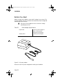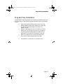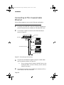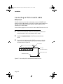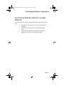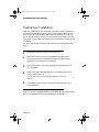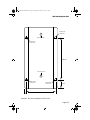
1
BNCHub 194-00A Book Page 1 Wednesday, October 15, 1997 3:51 PM
Asanté BNC Hub/6
for 10BASE-2 Networks
Installation Guide
BNCHub 194-00A Book Page 2 Wednesday, October 15, 1997 3:51 PM
BNCHub 194-00A Book Page 1 Wednesday, October 15, 1997 3:51 PM
Asanté BNC Hub/6
BNCHub 194-00A Book Page ii Wednesday, October 15, 1997 3:51 PM
Disclaimer
Information in this document is subject to change without notice and does
not represent a commitment on the part of Asanté Technologies, Inc. No
part of this manual, or any associated artwork, software, product design or
design concept, may be copied, reproduced or stored, in whole or in part,
in any form or by any means mechanical, electronic, optical, photocopying,
recording or otherwise, including translation to another language or format,
without the express written consent of Asanté Technologies, Inc.
Unless otherwise noted, all names of companies, products, addresses, and
persons contained herein are fictitious and are designed solely to document
the use of an Asanté Technologies product.
Copyright December1994, by Asanté Technologies, Inc.
Printed in Taiwan.
Manual Reorder # 06--00194-00 Rev. A
Trademarks
Asanté Technologies is a trademark of Asanté Technologies, Inc.
10T MAU, MacCon3 are trademarks of Asanté Technologies, Inc.
All other product names are trademarks or registered trademarks of their
respective companies.
Page ii
BNCHub 194-00A Book Page iii Wednesday, October 15, 1997 3:51 PM
FCC Information
This equipment is classified as a Class A computing device. Class A devices
may be used only in commercial, business, or industrial environments.
This equipment generates, uses, and can radiate radio frequency energy. If
this equipment is not insulated properly in strict accordance with the
instructions in this manual, then it may cause interference in its electronic
environment. This equipment has been tested and found to comply with the
limits for a Class A computing device pursuant to Subpart J of Part 15 of FCC
Rules, which are designed to provide reasonable protection against radio frequency interference when operated in a commercial environment.
Operation of this equipment in a residential area is likely to cause interference, in which case, the user, at his own risk and expense, will be required
to correct the interference.
Warranty
This Asanté BNC/6 product has a limited lifetime warranty which applies to
the original purchaser of the product. Asanté Technologies, Inc. warrants
that this product will be free from defects in title, materials and manufacturing workmanship. If the BNC/6product is found to be defective, then, as
your sole remedy and as the manufacturer’s only obligation, Asanté Technologies, Inc. will repair or replace the product provided that (1) you call
Asanté Technologies, Inc. for a Returned Merchandise Authorization (RMA)
number, that (2) you clearly write this RMA number on the outside of the
package, and that (3) you return it, postage prepaid, during the warranty
period.This warranty is exclusive and is limited to the Asanté BNC/6 product.
This limited lifetime warranty shall not apply to Asanté BNC/6 products that
have been subjected to abuse, misuse, abnormal electrical or environmental
conditions, or any condition other than what can be considered normal use.
∆
Note: The warranty card must be filed with Asanté
Technologies, Inc. within 30 days after date of purchase.
Page iii
BNCHub 194-00A Book Page iv Wednesday, October 15, 1997 3:51 PM
Warranty Disclaimers
Asanté Technologies, Inc. makes no other warranties, express, implied, or
otherwise, regarding the BNC/6, and specifically disclaims any warranty for
merchantability or fitness for a particular purpose.
The exclusion of implied warranties is not permitted in some states and the
exclusions specified herein may not apply to you. This warranty provides
you with specific legal rights. There may be other rights that you have
which vary from state to state.
Limitation of Liability
The liability of Asanté Technologies, Inc. arising from this warranty and sale
shall be limited to a refund of the purchase price. In no event shall Asanté
Technologies, Inc. be liable for costs of procurement of substitute products
or services, or for any lost profits, or for any consequential, incidental, direct
or indirect damages, however caused and on any theory of liability, arising
from this warranty and sale. These limitations shall apply notwithstanding
any failure of essential purpose of any limited remedy.
Page iv
BNCHub 194-00A Book Page v Wednesday, October 15, 1997 3:51 PM
Asking for assistance
Asking for assistance
To contact Asanté Technical Support:
Telephone
(800) 622-7464
(408) 435-0706
Fax
(408) 432-6018
Fax-Back1
(800) 741-8607
(408) 954-8607
Bulletin Board Service (BBS)2
(408) 432-1416
ARA
BBS2
(guest log in)
(408) 894-0765
AppleLink mail3/BBS2
ASANTE.TECH
FTP Archive2
ftp.asante.com
Internet
mail3
[email protected]
1. Please request catalog of contents.
2. Download INDEX.TXT file for catalog of contents.
3. When sending email, please include your full name, US mailing
address, phone number, product name, and a problem description.
Technical support hours
6:00 AM to 6:00 PM Pacific Standard Time USA, Monday–Friday
Page v
BNCHub 194-00A Book Page vi Wednesday, October 15, 1997 3:51 PM
Tell us what you think
Asanté Technologies is interested in your comments/suggestions about our
manuals. If you take the time to make suggestions, we’ll consider your suggestions for new manual releases.
Please read through this manual and think about these questions:
❏
❏
❏
What do you like best about this manual?
What do you think is the least valuable or weakest part
of this manual?
What is the most needed improvement you would make
to this manual?
Fax your comments and suggestions to:
Asanté Technical Publications at (408) 894-0363 or
E-mail them through Internet: [email protected]
Page vi
BNCHub 194-00A Book Page vii Wednesday, October 15, 1997 3:51 PM
Table of Contents
Disclaimer . . . . . . . . . . . . . . . . . . . . . . . . . . . . . . . . . . . . . . . . . . . . ii
Trademarks . . . . . . . . . . . . . . . . . . . . . . . . . . . . . . . . . . . . . . . . . . . ii
FCC Information . . . . . . . . . . . . . . . . . . . . . . . . . . . . . . . . . . . . . . iii
Warranty . . . . . . . . . . . . . . . . . . . . . . . . . . . . . . . . . . . . . . . . . . . . iii
Warranty Disclaimers . . . . . . . . . . . . . . . . . . . . . . . . . . . . . . . . . . .iv
Limitation of Liability . . . . . . . . . . . . . . . . . . . . . . . . . . . . . . . . . . .iv
Asking for assistance . . . . . . . . . . . . . . . . . . . . . . . . . . . . . . . . . . . . . . . . v
Technical support hours . . . . . . . . . . . . . . . . . . . . . . . . . . . . . . . . . v
Tell us what you think . . . . . . . . . . . . . . . . . . . . . . . . . . . . . . . . . . . . . vi
About the BNC Hub/6. . . . . . . . . . . . . . . . . . . . . . . . . . . . . . . . . . . . . xii
Check the Package . . . . . . . . . . . . . . . . . . . . . . . . . . . . . . . . . . . . xii
Features . . . . . . . . . . . . . . . . . . . . . . . . . . . . . . . . . . . . . . . . . . . . xiii
About This Manual . . . . . . . . . . . . . . . . . . . . . . . . . . . . . . . . . . . . . . . xiv
About 10BASE-2 . . . . . . . . . . . . . . . . . . . . . . . . . . . . . . . . . . . . . . . . . xv
Other Asanté Networking Products . . . . . . . . . . . . . . . . . . . . . . . . . . xvi
Planning a Network Installation . . . . . . . . . . . . . . . . . . . . . . 1-1
Before You Start. . . . . . . . . . . . . . . . . . . . . . . . . . . . . . . . . . . . . . . . . . 1-2
Assign a Network Manager . . . . . . . . . . . . . . . . . . . . . . . . . . . . . . . . . 1-3
Create a Network Map . . . . . . . . . . . . . . . . . . . . . . . . . . . . . . . . . . . . 1-4
Planning for Network Operations. . . . . . . . . . . . . . . . . . . . . . . . . . . . 1-5
Create a Network Log . . . . . . . . . . . . . . . . . . . . . . . . . . . . . . . . . .1-5
Consider Future Expansion . . . . . . . . . . . . . . . . . . . . . . . . . . . . . .1-5
Determine Application Needs . . . . . . . . . . . . . . . . . . . . . . . . . . . .1-5
Cabling Requirements . . . . . . . . . . . . . . . . . . . . . . . . . . . . . . . . . .1-5
Decide Where to Put the BNC Hub/6 . . . . . . . . . . . . . . . . . . . . . .1-6
Installation . . . . . . . . . . . . . . . . . . . . . . . . . . . . . . . . . . . . . . . 2-1
Before You Start. . . . . . . . . . . . . . . . . . . . . . . . . . . . . . . . . . . . . . . . . .
Plug and Play Installation . . . . . . . . . . . . . . . . . . . . . . . . . . . . . . . . . .
Connecting to Thin Coaxial Cable Ethernet . . . . . . . . . . . . . . . . . . . .
Connecting to Thick Coaxial Cable Ethernet . . . . . . . . . . . . . . . . . . .
Connecting Multiple Hubs for a Larger Network . . . . . . . . . . . . . . . .
2-2
2-3
2-4
2-6
2-7
Troubleshooting Your Network . . . . . . . . . . . . . . . . . . . . . . . 3-1
Page vii
BNCHub 194-00A Book Page viii Wednesday, October 15, 1997 3:51 PM
Before You Start. . . . . . . . . . . . . . . . . . . . . . . . . . . . . . . . . . . . . . . . . . 3-2
Interpreting the Hub LEDs . . . . . . . . . . . . . . . . . . . . . . . . . . . . . . . . . 3-3
Testing Your Installation . . . . . . . . . . . . . . . . . . . . . . . . . . . . . . . . . . . 3-4
Common Problems Found in the Hub . . . . . . . . . . . . . . . . . . . . . . . . 3-5
Common Cabling Problems and Solutions . . . . . . . . . . . . . . . . . .3-5
Common Workstation Problems and Solutions . . . . . . . . . . . . . .3-5
Common Hub Problems and Solutions . . . . . . . . . . . . . . . . . . . . .3-5
Network Management Software . . . . . . . . . . . . . . . . . . . . . . . . . .3-6
Cable Wiring Diagram . . . . . . . . . . . . . . . . . . . . . . . . . . . . . . . A-1
AUI (DB15) Connector . . . . . . . . . . . . . . . . . . . . . . . . . . . . . . . . . . . . A-2
Mounting the Hub . . . . . . . . . . . . . . . . . . . . . . . . . . . . . . . . . . B-1
Wall Mounting the Hub. . . . . . . . . . . . . . . . . . . . . . . . . . . . . . . . . . . . B-2
Technical Specifications . . . . . . . . . . . . . . . . . . . . . . . . . . . . . C-1
IEEE 802.3 Compliance . . . . . . . . . . . . . . . . . . . . . . . . . . . . . . . .
BNC Hub/6 . . . . . . . . . . . . . . . . . . . . . . . . . . . . . . . . . . . . . . . . .
Maximum Cable Lengths . . . . . . . . . . . . . . . . . . . . . . . . . . . . . . .
Physical Dimensions . . . . . . . . . . . . . . . . . . . . . . . . . . . . . . . . . .
Environment . . . . . . . . . . . . . . . . . . . . . . . . . . . . . . . . . . . . . . . .
Power Requirements . . . . . . . . . . . . . . . . . . . . . . . . . . . . . . . . . .
Power Supplied by AUI Port . . . . . . . . . . . . . . . . . . . . . . . . . . . .
Page viii
C-2
C-2
C-2
C-2
C-2
C-2
C-2
BNCHub 194-00A Book Page ix Wednesday, October 15, 1997 3:51 PM
List of Figures
Figure 1-1
Figure 1-2
Figure 1-3
Figure 1-4
Figure 2-1
Figure 2-2
Figure 2-3
Figure 0-2
Figure B-1
Linear bus topology . . . . . . . . . . . . . . . . . . . . . . . . . . . .
T-connector . . . . . . . . . . . . . . . . . . . . . . . . . . . . . . . . . .
Sample network map . . . . . . . . . . . . . . . . . . . . . . . . . . .
Attaching T-connector to a device . . . . . . . . . . . . . . . . .
AC power adapter . . . . . . . . . . . . . . . . . . . . . . . . . . . . .
Connecting to thin Ethernet. . . . . . . . . . . . . . . . . . . . . .
Connecting thick coaxial cable Ethernet to a hub . . . . .
AUI (DB15) Female Connector. . . . . . . . . . . . . . . . . . . .
Mounting template for BNC Hub/6 . . . . . . . . . . . . . . . .
1-2
1-2
1-4
1-6
2-2
2-4
2-6
A-2
B-3
Page ix
BNCHub 194-00A Book Page x Wednesday, October 15, 1997 3:51 PM
List of Tables
Table 2-1
Table 3-1
Table 0-1
Page x
Power Adapter Specifications . . . . . . . . . . . . . . . . . . . . . . . . 2-2
Hub LED Description . . . . . . . . . . . . . . . . . . . . . . . . . . . . . . 3-3
AUI Wiring Description . . . . . . . . . . . . . . . . . . . . . . . . . . . . . A-2
BNCHub 194-00A Book Page xi Wednesday, October 15, 1997 3:51 PM
Preface
•
About the BNC Hub/6 on page xii
•
About This Manual on page xiv
•
About 10BASE-2 on page xv
•
Other Asanté Networking Products
on page xvi
BNCHub 194-00A Book Page xii Wednesday, October 15, 1997 3:51 PM
About the BNC Hub/6
The Asanté™ BNC Hub/6 is a hardware device that lets you create high-performance Ethernet networks over thin coaxial cable. The BNC Hub/6 is a
low-cost, easy to use device that does not require complicated network management and is best suited to build small to medium sized networks. Asanté
also has a line of intelligent hubs that offer powerful network management
capability.
10BASE-2 is a standard defined by the Institute of Electrical and Electronic
Engineers (IEEE). This standard defines how Ethernet components interact
with each other on Local Area Networks (LANs) constructed of thin coaxial
cable. This chapter introduces the 10BASE-2 Asanté BNC Hub/6 and
describes the contents of the product package. It also provides information
about additional products you may need to use with the Asanté BNC Hub/6.
Asanté Technologies is committed to providing you with reliable products
and excellent technical support. Please feel free to call Asanté, or write us
with any questions, concerns, or suggestions.You can also reach us on-line
through AppleLink or the Internet.
Check the Package
Before going any further, examine this package and make sure that what you
have is the product you ordered.The package should contain:
❏
❏
❏
❏
❏
Page xii
One BNC Hub/6
One Installation Guide (this manual)
One wall mount power adapter matching the voltage of
your country
Six T-connectors
One wall-mount bracket
BNCHub 194-00A Book Page xiii Wednesday, October 15, 1997 3:51 PM
About the BNC Hub/6
Features
❏
❏
❏
❏
Cost effective, easy to use, plug-and-play unmanaged
hub requiring no switch setting
AUI port provided for thick Ethernet or external MAU
connection for maximum flexibility
Designed for both desktop and wall-mount application.
Large indicators aligned with the BNC connectors can
be viewed from any angle
BNC Hub/6 and Asanté 10T hubs have the same physical
dimensions, for easy mix-and-match mounting
Page xiii
BNCHub 194-00A Book Page xiv Wednesday, October 15, 1997 3:51 PM
About This Manual
This manual is divided into three chapters and three appendices:
Chapter 1, “Planning a Network Installation” on page 1-1, explains some
important considerations when designing and planning your network, and
provides the foundation for building reliable, easily managed, and expandable LANs.This is where to begin if you are not an experienced network
installer.
Chapter 2, “Installation” on page 2-1, shows you how to install the components of an Asanté Ethernet network. It tells you in detail how to configure
the Asanté BNC Hub/6, either as a stand-alone unit or within a larger network with multiple hubs.
Chapter 3, “Troubleshooting Your Network” on page 3-1, describes how to
interpret the BNC Hub/6 LEDs and how to troubleshoot common network
anomalies.
Appendix A, “Cable Wiring Diagram” on page A-1, covers the pin assignments for the AUI (DB15) connector on the BNC Hub/6.
Appendix B, “Mounting the Hub” on page B-1, provides simple instructions
for wall-mounting your hub.
Appendix C, “Technical Specifications” on page C-1, provides all technical
specifications for the BNC Hub/6.
Page xiv
BNCHub 194-00A Book Page xv Wednesday, October 15, 1997 3:51 PM
About 10BASE-2
About 10BASE-2
Thin Ethernet, as defined by the IEEE 802.3 specifications, is also called
10BASE-2. 10BASE-2 is similar to 10BaseT, but one way in which they differ
is in the type of cable used. A 10BaseT network uses unshielded, twistedpair (UTP) cable, while a 10BASE-2, or thin network, uses thin coaxial cable.
Some advantages to using coaxial cable include the fact that the cable is
widely used for network installations, it’s easy to install, and it withstands
outside interference better than twisted pair while maintaining the same
high transfer rate.
A thin Ethernet network is arranged in a linear or “bus” topology. The illustration below shows an example of this topology. In networking, topology
refers to the physical layout of the cabling and network devices. A bus topology uses a single cable to carry the network’s signals. Devices are connected directly to this cable, also known as a backbone cable.
The connections to the backbone cable are sometimes called taps. For thin
Ethernet connections, you use a BNC T-connector that attaches directly to a
BNC socket on a 10BASE-2-compatible adapter. The bus topology has two
ends that must be terminated electrically with a resistor (called a terminator)
to complete the bus.
Page xv
BNCHub 194-00A Book Page xvi Wednesday, October 15, 1997 3:51 PM
Other Asanté Networking Products
To connect your personal computers and other network devices to a BNC
Hub/6, you will need a 10BASE-2-compatible internal or external adapter for
each computer. Asanté Technologies provides a complete line of network
interface cards for PCs and the Macintosh, as well as a 10T, BNC, or fiber
MAU (Media Attachment Unit). All Asanté products support the latest IEEE
specifications.
Page xvi
BNCHub 194-00A Book Page 1 Wednesday, October 15, 1997 3:51 PM
1
Planning a Network Installation
•
Before You Start on page 1-2
•
Assign a Network Manager on page 1-3
•
Create a Network Map on page 1-4
•
Planning for Network Operations
on page 1-5
BNCHub 194-00A Book Page 2 Wednesday, October 15, 1997 3:51 PM
Planning a Network Installation
Before You Start
An efficient network that will serve your long-term needs requires thorough
planning.This chapter discusses some of the topics that are important in the
early stages of network development.The topics are arranged in chronological order.You should read this entire chapter to get an overview of the
details involved in planning your network.
Thin Ethernet networks are arranged in a linear bus topology, which uses
one length of cable (called a backbone cable) per network segment.
Figure 1-1 shows an example of a linear bus topology. The backbone cable
must have a terminator at each end, and one of the two terminators must be
grounded.
T-connectors
Terminator
Terminator
(grounded)
Thin coaxial cable
(backbone cable)
Figure 1-1 Linear bus topology
Workstations and servers connect to the backbone cable using T-connectors.
Figure 1-2 shows an illustration of a T-connector. Both sides of the T-connector must connect to cable or cable and a terminator.
Figure 1-2 T-connector
The BNC Hubs are well-suited to build networks or subnetworks of 180
nodes or less. If you plan to implement a large network with hundreds of
devices, you may consider investing in the Asanté intelligent hubs and a consultant to help you design your network.
Page 1-2
BNCHub 194-00A Book Page 3 Wednesday, October 15, 1997 3:51 PM
Assign a Network Manager
Assign a Network Manager
A network manager initially coordinates the design and installation of the
network. Once the network is up and running, the network manager is
responsible for adding new users to the network and troubleshooting problems. For small installations, the network manager’s duties may only require
a few hours a week. For larger installations, the network manager’s position
may be a full-time job.
Page 1-3
BNCHub 194-00A Book Page 4 Wednesday, October 15, 1997 3:51 PM
Planning a Network Installation
Create a Network Map
A network map is a visual record of your network configuration. Figure 1-3
shows a sample network map. Create a network map by copying a floor plan
diagram and adding graphics representing devices and cabling. Modify the
map as you change your plans, and use the completed map as a guide during
installation. It is a good idea to create the map on a computer so you can easily modify it.
Wiring
Closet
Figure 1-3 Sample network map
Page 1-4
BNCHub 194-00A Book Page 5 Wednesday, October 15, 1997 3:51 PM
Planning for Network Operations
Planning for Network Operations
Create a Network Log
A network log is a record of the names of devices, cable locations, wall-jack
numbers, and other information about the network. A simple network log
may contain the name, description, node number, and BNC Hub/6 port
number for each device on the network. A more detailed log may contain
the serial number of each device, the network number, and more. Consider
creating a network log to use as a reference when you are installing and
managing the network. An up-to-date network log ensures that records of
network equipment are always readily available. Having a complete written
record of your network will make troubleshooting easier.
Consider Future Expansion
As your network needs grow, your network should also grow. Hasty additions to your network make network maintenance difficult and time-consuming. Plan to install more cabling and T-connectors than you think you
will need. With adequate preparation, adding another device to the network
can often be as simple as plugging in another network connection.
Determine Application Needs
Think about how people on the network plan to use it. Will they be occasionally printing, exchanging electronic mail, or transferring files? Will some
users regularly access a multi-user database, transfer large graphics or CAD
files, or launch applications from a server? Depending upon your users’
application needs, you might want to break your network into smaller clusters (segments) using bridges and routers.
Cabling Requirements
There are several fundamental rules you must follow:
❏
❏
❏
The network must be arranged in a linear “bus” configuration.
Use only RG-58A/U coaxial cable. (RG-58U cable is similar, but it does NOT meet IEEE specifications.)
Each end of the linear cable must have a 50Ω terminator
installed.
Page 1-5
BNCHub 194-00A Book Page 6 Wednesday, October 15, 1997 3:51 PM
Planning a Network Installation
❏
❏
Ground only one of the two terminators. If your terminator doesn’t have a grounding strap, attach a length of
wire to it.Then attach the other end of the wire to the
center screw on an electrical outlet cover plate.
The coaxial cable BNC connector must attach directly to
a T-connector that attaches directly to the device.
Figure 1-4 shows an example. (Drop cables do NOT
meet IEEE specifications.)
Network device
BNC connector
Drop cable
Thin Ethernet
(coaxial) cable
T-connector
Figure 1-4 Attaching T-connector to a device
❏
❏
❏
❏
The maximum number of devices per segment is 30
(repeaters count as one device).
The minimum distance between devices is 0.5 meters
(1.6 feet).
The maximum segment length from hub to transceiver,
including the thin coaxial cable, is 185 meters (607
feet).
Use approved building wiring standards or consult a professional.
If the cable in your building does not meet the criteria specified above, or if
workstations are needed where no cable exists, you need to install new
cable.The above list is a brief overview, but this cable should conform to the
IEEE 802.3 Type 10BASE-2 specification.
Decide Where to Put the BNC Hub/6
You need to place the BNC Hub/6 in a location so that the distance of wire
between the BNC Hub/6 and any potential workstation is no greater than
185 meters (607 feet).
Page 1-6
BNCHub 194-00A Book Page 7 Wednesday, October 15, 1997 3:51 PM
Planning for Network Operations
Place the BNC Hub/6 in an area that is readily accessible for installation and
maintenance.The BNC Hub/6 must also be placed near an AC outlet. If you
are wiring a building that has multiple wiring closets, you may want to place
BNC Hubs in both the main wiring closet and satellite wiring closets.
The temperature and humidity requirements must fall within those specified
in Appendix A,“Technical Specifications.” Do not place the BNC Hub/6 near
sources of electrical interference, such as motors or heavy-current switches.
Page 1-7
BNCHub 194-00A Book Page 8 Wednesday, October 15, 1997 3:51 PM
Planning a Network Installation
Page 1-8
BNCHub 194-00A Book Page 1 Wednesday, October 15, 1997 3:51 PM
2
Installation
•
Before You Start on page 2-2
•
Plug and Play Installation on page 2-3
•
Connecting to Thin Coaxial Cable Ethernet
on page 2-4
•
Connecting Multiple Hubs for a Larger
Network on page 2-7
BNCHub 194-00A Book Page 2 Wednesday, October 15, 1997 3:51 PM
Installation
Before You Start
Before you begin the installation, check the AC voltage of your country.The
AC power adapter used with your BNC Hub should have the AC voltage that
matches that of your country.
▲
Table 2-1
Using an AC power adapter with an incorrect AC voltage
may damage your hub.
Power Adapter Specifications
Input Power
The AC power voltage of
your country power
electricity specification
Output power
12VAC @ 1.25 Ampere
Figure 2-1 AC power adapter
Be sure to check AC power voltage before starting the installation.
Page 2-2
BNCHub 194-00A Book Page 3 Wednesday, October 15, 1997 3:51 PM
Plug and Play Installation
Plug and Play Installation
The Asanté BNC Hub/6 is designed for plug and play installation. Before you
connect the hub to other devices, there are several things you should keep
in mind:
❏
❏
❏
∆
When connecting two Ethernet devices (such as a hub,
Ethernet adapter, or BNC MAU) together, you must make
sure that the total cable length is not less than 0.5
meters (1.6 feet).
Network cable segments can be connected to or disconnected from the hub while the power is on. Plugging in
or removing network cable segments while the hub is
operating will not interrupt the operation of the hub.
When you install the hub, you must avoid dusty locations, and avoid electromagnetically noisy areas.
A terminator is not required on unused BNC ports.
Page 2-3
BNCHub 194-00A Book Page 4 Wednesday, October 15, 1997 3:51 PM
Installation
Connecting to Thin Coaxial Cable
Ethernet
Do the following steps to connect a thin Ethernet configuration.
1
According to the IEEE 802.3 rules, a thin Ethernet segment supports 30 connections over a distance of 185 meters (607 feet).
2
A T-connector is used to connect the thin Ethernet cable, as
shown in Figure 2-2.
T-connector
Terminator
T-connector
Thin Ethernet segment
T-connector
Terminator (grounded)
Figure 2-2 Connecting to thin Ethernet
3
Connect other workstations together using thin coaxial cables
and T-connectors, as shown in Figure 2-2.
∆
4
Do not connect the thin cable to the BNC port or the
workstation BNC connector directly (that is, without
using a T-connector).
Connect the T-connector onto the BNC port and twist the T-connector sleeve to lock the connection.
Page 2-4
BNCHub 194-00A Book Page 5 Wednesday, October 15, 1997 3:51 PM
Connecting to Thin Coaxial Cable Ethernet
5
Make sure both ends of the thin Ethernet segment are terminated
by a 50Ω terminator.
Only one terminator end should be grounded, according to the
IEEE specification.
Page 2-5
BNCHub 194-00A Book Page 6 Wednesday, October 15, 1997 3:51 PM
Installation
Connecting to Thick Coaxial Cable
Ethernet
The AUI connector on the hub can be used to connect a 10BASE-5 thick
Ethernet coaxial cable segment to the hub.This allows network stations on
the thick coaxial cable to communicate with network stations on the
10BASE-2 thin coaxial cables.
Do the following steps to connect a thick coaxial cable Ethernet to the hub.
1
Make sure the transceiver cable (AUI cable) distance between the
transceiver and the hub is not greater than 50 meters.
2
Disable the SQE test function of the Ethernet external transceiver.
3
Connect the AUI cable to the AUI (DB15) connector on the hub
and connect the other side of the AUI cable to an external transceiver, as shown in Figure 2-3.
AUI connector
AUI cable
(less than 50 meters)
External transceiver
Thick Ethernet cable
Figure 2-3 Connecting thick coaxial cable Ethernet to a hub
Page 2-6
BNCHub 194-00A Book Page 7 Wednesday, October 15, 1997 3:51 PM
Connecting Multiple Hubs for a Larger Network
Connecting Multiple Hubs for a Larger
Network
You have three choices when connecting networks with more than one
hub:
❏
❏
❏
Use a BNC port on the hub to connect to a thin Ethernet
backbone.
Use the AUI port to connect to a thick Ethernet backbone.
Use the AUI port and an external MAU to connect to a
media of your choice, such as fiber optic cable.
Page 2-7
BNCHub 194-00A Book Page 8 Wednesday, October 15, 1997 3:51 PM
Installation
Page 2-8
BNCHub 194-00A Book Page 1 Wednesday, October 15, 1997 3:51 PM
3
Troubleshooting Your Network
•
Before You Start on page 3-2
•
Interpreting the Hub LEDs on page 3-3
•
Testing Your Installation on page 3-4
•
Common Problems Found in the Hub
on page 3-5
BNCHub 194-00A Book Page 2 Wednesday, October 15, 1997 3:51 PM
Troubleshooting Your Network
Before You Start
You test and monitor your network’s status with the aid of the LEDs on the
hub, the network interface card, or the BNC MAU. In general, the LEDs give
information about the status of a particular unit or function.This section
covers how to read the LEDs, both when testing your installation and during
normal network operation.
The hub does not require any routine maintenance because it doesn’t contain any fans or other mechanical devices on which its operation depends. If
you cannot identify and correct a fault using the testing procedures
described in this chapter, contact Asanté Technical Support.There are no
user-serviceable parts in the Asanté BNC Hub/6.
Page 3-2
BNCHub 194-00A Book Page 3 Wednesday, October 15, 1997 3:51 PM
Interpreting the Hub LEDs
Interpreting the Hub LEDs
When you first turn on your Asanté BNC Hub/6, all the LEDs switch ON
while the hub goes through a series of internal diagnostics to ensure its reliable operation. After the diagnostics have been completed, each LED indicates a different condition. Below is a description of each LED.
Table 3-1
LED Name
Power/Traffic
Hub LED Description
Functional Definition
A steady green LED indicates that power
is applied to the hub.
The LED will blink on and off to indicate
network traffic.
Link Status
Each Link Status LED above the BNC port
indicates the link status of the
corresponding port.
A steady green LED indicates that the
Link Status test has passed and the
workstation connections to the hub are
good.
No light indicates that the connection
may be broken. If any of the thin cable on
a segment is disconnected, all the
connections on that BNC segment will be
broken.
To be sure that the connection from the
hub to the workstation is also good, you
should also check the link status light on
the adapter card.
Collision
Each Collision LED above the BNC port
indicates collisions on the network.
A yellow light indicates a collision has
occurred.
Page 3-3
BNCHub 194-00A Book Page 4 Wednesday, October 15, 1997 3:51 PM
Troubleshooting Your Network
Testing Your Installation
After your installed wiring is connected, you need to test the installation.
You do this by testing two network devices that communicate with one
another, such as one workstation and one file server. When you have one
pair of devices working correctly, you will have verified that the hub functions and will know that the link between the workstation and the file server
is complete.
If the two devices cannot communicate, follow the procedure described
below.
1
Make sure the power indicator on the hub is on.
2
Make sure that the wiring is correct between the hub and the
devices connected to it and that both have Link Status LEDs on.
See Figure 2-2 on page 2-4 for an example.
3
Make sure that both ends of each segment are terminated with a
50Ω terminator.
4
Make sure that all individual devices can communicate with one
another without the hub.
You can check this out by forming a network of only two
devices.
5
If all devices communicate, concentrate on eliminating wiring or
hub malfunctions.
Following are some suggested areas to check, depending on what the problem is. If the problem persists, call Asanté Technical Support.
Page 3-4
BNCHub 194-00A Book Page 5 Wednesday, October 15, 1997 3:51 PM
Common Problems Found in the Hub
Common Problems Found in the Hub
Link Status LED is off.
Probable cause is a T-connector not making contact. Check all T- connectors and make sure both ends of each segment are terminated.
BNC port doesn’t have proper termination.
The BNC Hub/6 is not auto-terminating.Terminate the BNC port.
Following are suggested areas to check depending on what the problem is.
If the problems persist, call Asanté Technical Support.
Common Cabling Problems and Solutions
❏
RG-58U coaxial cable is used.
Use only RG-58 A/U coaxial cable.
Common Workstation Problems and Solutions
❏
❏
❏
❏
❏
Thin coaxial cable is broken or improperly connected.
Check connections and continuity.
BNC connector is broken or improperly connected.
Check connections and continuity.
Network interface card hardware is not configured properly.
Proper application software is not running on workstation to provide connection (i.e., make sure you are running TCP/IP software when talking to a UNIX host
system).
Workstation is not operating properly.
Take workstation to an authorized service center to
ensure proper operation.
Common Hub Problems and Solutions
❏
❏
❏
Power is not connected to hub.
Thin coaxial cable segment length is too long.
Check cable length to be sure it does not exceed IEEE
specification of 185 meters (607 feet).
More than 30 devices per network segment.
Remove devices until there are fewer than 30 on the network segment.
Page 3-5
BNCHub 194-00A Book Page 6 Wednesday, October 15, 1997 3:51 PM
Troubleshooting Your Network
❏
Thin coaxial cable is shorted out or cut.
Check integrity and continuity of cable.
Network Management Software
Network management applications can be categorized into two groups —
network analyzers and protocol analyzers.
Below you will find a list of network management applications that Asanté
has found to be very useful in diagnosing network problems.This list is for
information only, as a service to our customers, and does not constitute an
endorsement by Asanté Technologies, Inc.The list contains the product
name, the manufacturer, and the platform the application software runs on.
Product
Manufacturer
Platform
Analyzer
Category
EtherPeek
The AG Group, Inc.
Mac
Protocol
NetMinder Ethernet
Neon Software
Mac
Protocol
Sniffer
Network General
DOS
Network
WatchDog
Network General
DOS
Network
Page 3-6
BNCHub 194-00A Book Page 1 Wednesday, October 15, 1997 3:51 PM
A
Cable Wiring Diagram
•
AUI (DB15) Connector on page A-2
BNCHub 194-00A Book Page 2 Wednesday, October 15, 1997 3:51 PM
AUI (DB15) Connector
Table 0-1
AUI Wiring Description
Pin
Symbol
Pairs
3
DO+
Transmit
Data Out +
10
DO-
Pair
Data Out -
11
DO S
5
DI+
Receive
Data In +
12
DI-
Pair
Data In -
4
DI S
Data In Shield
7
NC
Not Connected
15
NC
Not Connected
8
NC
GND
2
Cl+
Collision
Control In +
9
Cl-
Pair
Control In -
1
Cl S
6
VC
Power
Voltage Common
13
VP
Pair
Voltage Plus
14
VS
Voltage Shield
Shell
PG
Protective Ground
Data Out Shield
Control Shield
8 7 6 5 4 3 2 1
151413121110 9
Figure 0-2
Page A-2
Used
AUI (DB15) Female Connector
BNCHub 194-00A Book Page 1 Wednesday, October 15, 1997 3:51 PM
B
Mounting the Hub
•
Wall Mounting the Hub on page B-2
BNCHub 194-00A Book Page 2 Wednesday, October 15, 1997 3:51 PM
Wall Mounting the Hub
Your hub can be used as a desktop unit or as a wall-mount unit. A wallmount bracket and four screws are provided in the package. Two keyhole
slots are provided on the bottom of the hub so that it can be mounted on a
surface, such as a wall or the underside of a counter top.
To mount the hub, use the template on the next page to locate the screws in
the wall and follow the directions below.
1
Screw four 1 inch long (#4–32) wood screws 3" into the wallmount screw holes.
2
Screw two 3/4 inch long (#6–32) pan head machine screws into
the key screw holes, leaving approximately 0.15 inch of the
threads exposed.
3
Hang the hub on the wall using the keyholes provided on the
bottom of the hub.
Page B-2
BNCHub 194-00A Book Page 3 Wednesday, October 15, 1997 3:51 PM
Wall Mounting the Hub
Wall-mount
screw hole
Key screw hole
Wall-mount
screw hole
9.8 cm
Key screw hole
Wall-mount
screw hole
.5
cm
Wall-mount
screw hole
2 cm
7 cm
Figure B-1 Mounting template for BNC Hub/6
Page B-3
BNCHub 194-00A Book Page 4 Wednesday, October 15, 1997 3:51 PM
Page B-4
BNCHub 194-00A Book Page 1 Wednesday, October 15, 1997 3:51 PM
C
Technical Specifications
BNCHub 194-00A Book Page 2 Wednesday, October 15, 1997 3:51 PM
IEEE 802.3 Compliance
❏
❏
10BASE-2 (thin, BNC)
10BASE-5 (thick, AUI)
BNC Hub/6
❏
Six BNC ports and one AUI port; both port types may be
used at the same time
Maximum Cable Lengths
❏
❏
10BASE-5 (thick Ethernet, AUI): 50 meters maximum to
Ethernet MAU (transceiver) with shielded, twisted-pair
drop cable
10BASE-2 (thin Ethernet, BNC): 185 meters maximum
per segment
Physical Dimensions
❏
8.6 inches x 5.3 inches x 1.35 inches (LxWxH)
Environment
❏
❏
Temperature: Operating 0 degrees C to +50 degrees C
Storage –20 degrees C to +70 degrees C
Humidity:
Operating 10% to 80% RH
Storage 5% to 90% RH
Power Requirements
❏
❏
❏
Input voltage to wall-mount power adapter: voltage
matched to voltage of country in which unit is being
used, 30 watts minimum
Frequency: 47 Hz to 63 Hz
Output Voltage: 12 Volt AC @ 1.25 Ampere, 15 VA maximum
Power Supplied by AUI Port
❏
Page C-2
+13 Volt DC, 500 mA maximum
BNCHub 194-00A Book Page i Wednesday, October 15, 1997 3:51 PM
Index
Numerics
10BASE-2
about xii
described xv
10BASE-5 thick Ethernet 2-6
50Ω terminator 1-5, 2-5
A
AC power voltage 2-2
adapters, requirements for xvi
adding network devices 1-5
assigning a network manager 1-3
attaching T-connector to device 1-6
AUI cable. See transceiver cable
AUI connector 2-6, A-2
AUI port xiii, 2-7
B
BNC Hub/6
about xii
common problems found 3-5
features xiii
BNC MAU 2-3
BNC ports 2-3, 2-7, 3-5
BNC T-connector 2-4
bus topology xv
C
cable length, maximum 2-3, C-2
cable segment,10BASE-5 thick Ethernet 2-6
cabling requirements 1-5
Collision LEDs 3-3
common problems in hubs 3-5
connecting a hub
to other devices 2-3
to thick Ethernet 2-6
to thin Ethernet 2-4
connecting multiple hubs 2-7
connecting network segments 2-3
connectors
AUI 2-6, A-2
BNC 2-4
DB15. See AUI connector
Index i
BNCHub 194-00A Book Page ii Wednesday, October 15, 1997 3:51 PM
MAU xiii, 2-7
T-connector 3-5
creating network log 1-5
creating network map 1-4
D
DB15 connector. See AUI connector
determining hub location 1-6
devices cannot communicate 3-4
disconnecting cable segments 2-3
drop cables 1-6
dust and hub installation 2-3
E
electrical interference and hub location 1-7
electromagnetic noise and hub installation 2-3
eliminating wiring or hub malfunctions 3-4
environmental requirements C-2
Ethernet
thick backbone 2-7
thin backbone xv, 2-7
expansion, considering future 1-5
external transceiver 2-6
F
features of BNC Hub/6 xiii
fiber optic cable 2-7
future expansion, considering 1-5
G
grounding requirements 1-6
grounding thin Ethernet 2-5
H
hubs
connecting multiple 2-7
LED description 3-3
Index ii
BNCHub 194-00A Book Page iii Wednesday, October 15, 1997 3:51 PM
I
IEEE specifications
Asanté product support for xvi
for wiring 1-6
input power specifications 2-2
installation and hub location 1-7
installation, network
planning 1-1
using a consultant 1-2
internal diagnostics 3-3
interpreting hub LEDs 3-3
K
keyhole slots on hub B-2
L
LEDs, interpreting 3-3
Link Status LEDs 3-3, 3-4, 3-5
location, determining hub 1-6
M
manager, network
assigning 1-3
responsibilities 1-3
map, network
creating 1-4
as installation guide 1-4
sample 1-4
MAU connection xiii, 2-7
maximum number of devices 1-6
minimum distance between devices 1-6
monitoring network status 3-2
multiple hubs, connecting 2-7
N
network cable segments 2-3
network installation
planning 1-1
testing 3-4
using a consultant 1-2
network interface cards xvi
network log, creating 1-5
network manager
Index iii
BNCHub 194-00A Book Page iv Wednesday, October 15, 1997 3:51 PM
assigning 1-3
responsibilities 1-3
network map
creating 1-4
as installation guide 1-4
sample 1-4
O
output power specifications 2-2
P
physical dimensions C-2
planning
network installation 1-1
for network operations 1-5
plug and play installation 2-3
plugging in network segments 2-3
ports
AUI xiii, 2-7
BNC 2-7, 3-5
power adapter specifications 2-2
Power/Traffic LED 3-3
products, other Asanté xvi
R
removing network segments 2-3
RG-58A/U coaxial cable 1-5
routine maintenance 3-2
rules for cable wiring 1-5
S
specifications, power adapter 2-2
SQE 2-6
standards, support for xvi, 1-6
status light, adapter card 3-3
T
T-connector
attaching to device 1-6
checking 3-5
terminating BNC port 3-5
terminating thin Ethernet 2-5
terminator 2-3
testing network installation 3-4
Page -iv
BNCHub 194-00A Book Page v Wednesday, October 15, 1997 3:51 PM
testing network status 3-2
thick Ethernet backbone 2-7
thin Ethernet backbone 2-7
thin Ethernet segment, number of connections 2-4
thin Ethernet, about xv
thin net cable, maximum link-length 1-6
topology, bus xv
transceiver cable 2-6
transceiver, external 2-6
troubleshooting 3-2
U
user-serviceable parts 3-2
V
verifying hub functioning 3-4
W
wall mounting the hub B-2
wire distance and hub location 1-6
wiring closets and hub location 1-7
wiring diagram, AUI (DB15) A-2
workstation and file server link 3-4
Page -v
BNCHub 194-00A Book Page 4 Wednesday, October 15, 1997 3:51 PM
BNCHub 194-00A Book Page 5 Wednesday, October 15, 1997 3:51 PM
BNCHub 194-00A Book Page 6 Wednesday, October 15, 1997 3:51 PM
BNCHub 194-00A Book Page 7 Wednesday, October 15, 1997 3:51 PM
BNCHub 194-00A Book Page 8 Wednesday, October 15, 1997 3:51 PM
Asanté Technologies, Inc.
821 Fox Lane
San Jose, CA 95131
December 1994
Part Number 06-00194-00 Rev. A
Printed in Taiwan