1
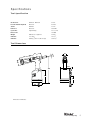
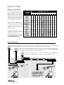
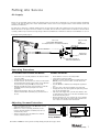
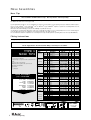
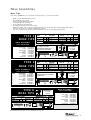
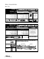
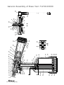
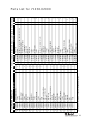
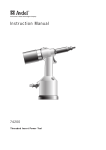
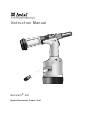
Instruction Manual
4
Genesis® G4
H y d ro - P n e u m a t i c P o w e r To o l
Contents
Safety Rules
4
Specifications
Tool Specifications
Tool Dimensions
5
5
Intent of Use
Range of Fasteners
Part Numbering
6
6
Putting into Service
Air Supply
Operating Procedure
Adjusting Vacuum Extraction
7
7
7
Nose Assemblies
Nose Tips
Fitting Instructions
Fitting Instructions for Maxlok® and Avtainer®
Servicing Instructions for all Nose Assemblies
8-10
8
11
11
Accessories
Stem Deflector
Extension
Side Ejector
12
12
12
Servicing the Tool
Daily / Weekly / Monthly
Moly Lithium Grease EP 3753 Safety Data
MolyKote 55m & MolyKote 111 Safety Data
Annually
Service Kit
Head Assembly
Pneumatic Piston Assembly
Valve Spool Assembly
Trigger
13
13
14
15
15
15-16
16
16
16
General Assembly of Base Tools
General Assembly and Parts List
18-19
Priming
Oil Details
Hyspin VG 32 Safety Data
Priming Kit
Priming Procedure
20
20
20
21
Fault Diagnosis
Symptom, Possible Cause & Remedy
22-23
Warranty
Avdel installation tools carry a 12 month warranty against defects caused by faulty
materials or workmanship, the warranty period commencing from the date of delivery
confirmed by invoice or delivery note.
The warranty applies to the user/purchaser when sold through an authorised outlet, and
only when used for the intended purpose. The warranty is invalidated if the installation tool
is not serviced, maintained and operated according to the instructions contained in the
Instruction and Service Manuals.
In the event of a defect or failure, and at its sole discretion, Avdel undertakes only to repair
or replace faulty components.
Avdel UK Limited policy is one of continuous product development and improvement and we reserve the right to change the specification of any product without prior notice.
3
Safety Rules
This instruction manual must be read with particular attention to the following safety rules, by any person
installing, operating, or servicing this tool.
1
Do not use outside the design intent.
2
Do not use equipment with this tool/machine other than that recommended and supplied by Avdel UK Limited.
3
Any modification undertaken by the customer to the tool/machine, nose assemblies, accessories or any equipment supplied by Avdel UK
Limited or their representatives, shall be the customer’s entire responsibility. Avdel UK Limited will be pleased to advise upon any
proposed modification.
4
The tool/machine must be maintained in a safe working condition at all times and examined at regular intervals for damage and function
by trained competent personnel. The Plastic Body and Base Cover must be changed after approximately 1 million cycles or whenever
there is evidence of impact damage, chipping or cracks. Any dismantling procedure shall be undertaken only by personnel trained in Avdel
UK Limited procedures. Do not dismantle this tool/machine without prior reference to the maintenance instructions. Please contact Avdel
UK Limited with your training requirements.
5
The tool/machine shall at all times be operated in accordance with relevant Health and Safety legislation. In the U.K. the “Health and
Safety at Work etc. Act 1974” applies. Any question regarding the correct operation of the tool/machine and operator safety should be
directed to Avdel UK Limited.
6
The precautions to be observed when using this tool/machine must be explained by the customer to all operators.
7
Always disconnect the airline from the tool/machine inlet before attempting to adjust, fit or remove a nose assembly.
8
Do not operate a tool/machine that is directed towards any person(s) or the operator.
9
Always adopt a firm footing or a stable position before operating the tool/machine.
10 Ensure that vent holes do not become blocked or covered.
11 The operating pressure shall not exceed 7 bar.
12 Do not operate the tool if it is not fitted with a complete nose assembly or swivel head unless specifically instructed otherwise.
13 Care shall be taken to ensure that spent stems are not allowed to create a hazard.
14 If the tool is fitted with a stem collector,it must be emptied when half full.
15 If the tool is fitted with a stem deflector, it should be rotated until the aperture is facing way from the operator and other person(s) working
in the vicinity.
16 When using the tool, the wearing of safety glasses is required both by the operator and others in the vicinity to protect against fastener
ejection, should a fastener be placed ‘in air’. We recommend wearing gloves if there are sharp edges or corners on the application. Any
such sharp features must not be allowed to indent or otherwise damage the plastic body or End Cap of the tool - see Safety Rule 4. Do
not operate the tool if it is not fitted with a Rubber Base Cover.
17 Take care to avoid entanglement of loose clothes, ties, long hair, cleaning rags etc. in the moving parts of the tool which should be kept
dry and clean for best possible grip.
18 When carrying the tool from place to place keep hands away from the trigger/lever to avoid inadvertent start up.
19 Excessive contact with hydraulic fluid oil should be avoided. To minimize the possibility of rashes, care should be taken to wash
thoroughly.
20 C.O.S.H.H. data for all hydraulic oils and lubricants is available on request from your tool supplier.
4
Specifications
To o l S p e c i f i c a t i o n
Air Pressure
Minimum - Maximum
5-7 bar
Free Air Volume Required
@ 5.5 bar
4.3 litres
Stroke
Minimum
17 mm
Pull Force
@ 5.5 bar
18.68 kN
Cycle time
Approximately
1.5 seconds
Weight
Without nose equipment
1.64 kg
Vibration
Less than
Utilising 1/4 STL Lockbolt equip
2.5 m/s2
Noise Level
75 dB(A)
Vibration
3.58 m/s2
To o l D i m e n s i o n s
30'
12°
145
116
30
70
316
134
4
152
150
128
Dimensions in millimetres.
5
Intent of Use
Range of Fasteners
G4 is a hydro-pneumatic tool designed
to place Avdel® breakstem fasteners at
high speed making it ideal for batch or
flow-line assembly in a wide variety of
applications throughout light / medium
industries where the plastic components
will not be subject to impact damage. It
can place all fasteners listed opposite.
The tool features an adjustable vacuum
system for fastener retention and trouble
free collection of the spent stems
regardless of tool orientation. See the
‘Operating Procedure’ on page 7 for
adjustment instructions.
A complete tool is made up of three
separate elements which will be supplied
individually. See diagram below.
NOSE EQUIPMENT MUST BE FITTED
AS DESCRIBED ON PAGES 8-11.
FASTENER
NAME
FASTENER SIZE (
MM
IN
)
4.3 4.8
5
5.2
6
6.4
6.5
7
8
9
9.5 10
3/16
–
–
–
1/ 4
–
–
–
–
3/ 8
–
AVEX ®
STAVEX ®
●
●
●
●
AVINOX ®
AVIBULB ®
●
BULBEX ®
●
●
T-LOK ®
AVDEL ® SR
●
–
●
●
●
●
INTERLOCK ®
HEMLOK ®
●
●
TLR ®
●
●
MAXLOK ®
AVTAINER ®
●
●
AVDEL ®
MBC
●
MBC/LC
●
●
●
●
AVSEAL ®
●
Q TM RIVET
T TM RIVET
CHERRYMATE TM
●
●
●
●
●
●
●
●
Part Numbering
1
The part number of the base tool remains the same whichever nose assembly, or nose tip is fitted. See the General Assembly
pages 18-19. If a Maxlok® nose assembly is fitted, the same base tool MUST be adapted. See details page 11.
2
This single nose assembly will allow placing of non-aerospace fasteners by simply selecting the appropriate nose
tip from the range of type 1 nose tips. Other nose assemblies are available for applications with restricted
access, for aerospace and special fasteners. See tables pages 8-10.
3
3
2
1
The nose tip part number relates to a specific fastener. If access to the application is
restricted, some extended nose tips are available. See ‘type 2 nose tip’ table page 9.
NOSE TIP
see note 3
+
1
2
+
3
=
COMPLETE TOOL
71230-00 . . .
NOSE ASSEMBLY
71210-15000
BASE TOOL
71230-02000
*
4
6
ADD 3 DIGITS FROM THE
LAST COLUMN OF A NOSE TIP
TABLE ON PAGE 8, 9 OR 10.
FOR MAXLOK®, USE MAXLOK®
TABLE PAGE 10 EVEN THOUGH
THERE IS NO NOSE TIP.
4
*
Putting into Service
Air Supply
All tools are operated with compressed air at an optimum pressure of 5.5 bar. We recommend the use of pressure regulators and filtering
systems on the main air supply. These should be fitted within 3 metres of the tool (see diagram below) to ensure maximum tool life and
minimum tool maintenance.
Air supply hoses should have a minimum working effective pressure rating of 150% of the maximum pressure produced in the system or
10 bar, whichever is the highest. Air hoses should be oil resistant, have an abrasion resistant exterior and should be armoured where
operating conditions may result in hoses being damaged. All air hoses MUST have a minimum bore diameter of 6.4 millimetres or 1/4 inch.
Read daily servicing details page 13.
STOP COCK
(USED DURING MAINTENANCE
OF FILTER/REGULATOR OR LUBRICATION UNITS)
TAKE OFF POINT
FROM
MAIN SUPPLY
3 METRES MAXIMUM
0 2 4
1416
12
6 8 10
MAIN SUPPLY
DRAIN POINT
4
PRESSURE REGULATOR
AND FILTER (DRAIN DAILY)
O p e r a t i n g P ro c e d u r e
ALL FASTENERS EXCEPT AVTAINER® AND MAXLOK®
AVTAINER® AND MAXLOK®
•
•
•
•
•
•
•
•
Ensure that a nose assembly suitable for the fastener is fitted
(see pages 8-10).
Connect the tool to the air supply.
Insert the fastener stem into the nose of the tool. The fastener
should remain held in by the vacuum system. If not, adjust the
vacuum extraction rotary valve 65 (see note below).
Bring the tool with the fastener to the application so that the
protruding fastener enters squarely the hole of the
application.
Fully actuate the trigger. The tool cycle will broach the
fastener and the broken stem will be projected to the rear of
the tool .
•
•
•
•
•
Ensure that the correct nose assembly is fitted.
Connect the tool to the air supply.
Disable the vacuum extraction system by turning rotary valve
65 until you feel or hear no air flow out of the front of the
nose assembly.
Push the Maxlok® or Avtainer® stem through the application
hole.
Place the collar on the stem (orientation as shown below).
Keeping the head of the stem against the application, push the
tool onto the protruding stem.
Fully depress the trigger. One cycle will ensure that the collar
is swaged into the lock grooves of the stem and that the stem
breaks at the breaker groove.
Release the trigger. The tool completes its cycle by pushing
itself off the collar and the spent stem will be pushed to the
rear of the tool on insertion of the next fastener.
A d j u s t i n g Va c u u m E x t r a c t i o n
•
•
•
Using a screwdriver, turn rotary valve 65 until the air flow
at the rear of the tool ceases.
With the nose of the tool pointing downwards, insert a
fastener other than Avtainer® or Maxlok®, into the nose
and hold it into position.
Turn the rotary valve either way until there is sufficient
suction to retain the fastener.
Placing AVTAINER®
Placing MAXLOK®
Item numbers in bold refer to the general assembly drawing and parts list on pages 18-19.
7
Nose Assemblies
Nose Tips
I M P O R TA N T
Nose assemblies do NOT include nose tips. Nose tips must be ordered separately.
A tool must always be fitted with the correct nose assembly and nose tip for your fastener and must be ordered separately, refer to
the ‘NOSE TIPS’ tables below and pages 9-10.
If your application presents no access restriction use a type 1 nose tip unless you are placing aerospace fasteners which require a
type 3 nose tip, Avtainer® a type 5, Hemlok® and 1/4” Interlock® a type 6. Maxlok® requires a special nose assembly which does not
make use of any nose tip, see pages 10-11.
Dimensions ‘A’ and ‘B’ will help you assess the suitability of a particular nose tip.
You should also check that the dimensions of the nose casing will not restrict access to your application. If access is restricted type 2
nose tips with extra reach, are available for some fasteners. Refer to the table on page 9.
It is essential that a fastener-compatible nose assembly and nose tip are fitted prior to operating the tool (no nose tip with Maxlok®).
Fitting Instructions
See page 9, except for Avtainer® and Maxlok® see page 11.
I M P O R TA N T
The air supply must be disconnected when fitting or removing nose assemblies.
FASTENER
MATERIAL
Ø1
3 / 16 4.8
Aluminium
AVEX ®
3 / 16 4.8
Aluminium
Large flange
3 / 16 4.8
Steel
3 / 16 4.8
Aluminium
1/4
6.4 Aluminium
3 / 16 4.8
Steel
STAVEX®
3 / 16 4.8
Steel
Countersunk
3 / 16 4.8
Stainless Steel
3 / 16 4.8
Steel
Large flange
1/4
6.4 Steel
3 / 16
BULBEX ®
4.8 Aluminium
–
Aluminium
AVSEAL ®
8
–
Aluminium
8
–
Aluminium
9
–
Aluminium
9
–
10 Aluminium
–
10 Aluminium
3 / 16 4.8
Aluminium
TLR ®
1/4
6.4 Aluminium
3 / 16 4.8
Stainless Steel
AVINOX ® II
–
T-LOK ®
4.3 Steel
3/ 16
4.8 Steel
3 / 16
AVIBULB ®
4.8 Steel
–
Steel
6
AVDEL ® SR 3/16 4.8 Any
1/4
6.4 Any
3 / 16 4.8
Any
INTERLOCK ® 3/16 4.8 Any
3 / 16
Q™ RIVET
4.8 Any
1/4
6.4 Any
CHERRYMATE® 3/16 4.8 Any
1/4
6.4 Any
T™ RIVET
3/16 4.8
Al/Al 4
Large flange
3/16 4.8
Al/Al 4
3/16 4.8
Al/Steel 4
Large flange
3/16 4.8
Al/Steel 4
6.4 Al/Al 4
1/4
Large flange
6.4 Al/Al 4
1/4
6.4 Al/Steel 4
1/4
Large flange
6.4 Al/Steel 4
1/4
TYPE 1
NAME
NOSE TIPS
1
2
In inches then in millimetres.
Head forming nose tips for use with countersunk heads
ONLY.
3 Long nose tip for deep placing.
4 Material of the body then of the stem. 'Al' is the
abbreviation for Aluminium.
5
6
Domehead.
Countersunk.
NOSE ASSEMBLY
part nº 71210-15000
ITEM
1
2
3
4
5
6
7
8
DESCRIPTION
NOSE CASING
'O' RING
JAW HOUSING
JAWS
JAW SPREADER
BUFFER
SPRING
LOCKING RING
PART Nº
07340-00306
07003-00067
07340-00304
71210-15001
07498-04502
71210-05001
07500-00418
07340-00327
NOSE TIP (mm)
PART Nº
'A'
'B'
07381-04701 12.7 2.8
07340-04800 19.0 3.3
07490-04401 12.7 3.3
07340-066012 12.7 4.1
07612-02001 12.7 3.3
07381-04701 19.0 3.3
07381-04701 12.7 2.8
07381-04701 12.7 2.8
07340-04800 12.7 2.8
07612-02001 12.7 2.8
07381-04701 12.7 2.8
71220-16006 12.7 5.5
71220-160113 12.7 7.3
71220-16007 12.7 5.6
71220-160123 12.7 7.3
71220-16008 12.7 5.6
71220-160133 12.7 7.3
07605-00220 12.7 4.1
71220-16080 12.7 4.4
07498-01401 12.7 4.8
07340-06201 12.7 3.3
07340-06201 12.7 3.3
07498-01401 12.7 4.8
07612-02001 12.7 3.3
07348-070015 12.7 5.7
71220-60001 12.7 3.3
71210-160506 12.7 5.7
07381-04701 12.7 2.8
07340-06201 12.7 3.3
07612-02001 12.7 3.3
07340-06201 12.7 3.3
07612-02001 12.7 3.3
703-A-25-6TA 15.9 9.5
703-B-21
12.7 8.0
703-A-25-6T 15.9 9.5
703-B-26
12.7 9.0
743-A-25-8TA 17.5 11.2
743-B-21
12.7 8.0
743-A-25-8T 16.7 10.2
743-B-26
12.7 8.3
A
22.9
8
8
7
6
5
4
3
2
1
61
B
see
below
…010
…016
…017
…015
…021
…016
…010
…010
…010
…021
…010
…165
…185
…166
…186
…167
…187
…140
…141
…082
…120
…120
…082
…021
…062
…063
…064
…010
…120
…021
…120
…021
…380
…381
…383
…384
…385
…386
…387
…388
COMPLETE TOOL
PART NUMBER :
precede with
71230-00
Nose Assemblies
Nose Tips
Item numbers in bold refer to nose assembly components in type 1,2, 3 and 6 nose tip tables.
•
•
•
•
•
•
•
•
•
Lightly coat jaws 4 with Moly lithium grease*.
Drop jaws 4 into jaw housing 3.
Insert jaw spreader 5 into jaw housing 3.
Locate buffer 6 on jaw spreader 5.
Locate spring 7 onto jaw spreader 5.
Fit locking ring 8 onto the jaw spreader housing.
Holding tool pointing down, screw the assembled jaw housing onto the jaw spreader housing and tighten with spanner*.
Screw the nose tip into nose casing 1 and tighten with spanner*.
Place nose casing 1 with ‘O’ ring 2 over jaw housing 3 and screw onto the tool, tightening with spanner*.
TYPE 2
NAME
AVEX ®
NOSE TIPS
NOSE ASSEMBLY
DESCRIPTION
NOSE CASING
'O' RING
JAW HOUSING
JAWS
JAW SPREADER
BUFFER
SPRING
LOCKING RING
TYPE 2 NOSE TIPS ARE EXTENDED
PART Nº
07340-02804
07003-00067
07340-00304
71210-15001
07498-04502
71210-05001
07500-00418
07340-00327
APPLICATIONS WHERE TYPE 1
NOSE ASSEMBLY
22.9
8
7
6 5
In inches then in millimetres.
5
4
COMPLETE TOOL
PART NUMBER :
precede with
71230-00
A
B
LISTED ABOVE.
22.9
8
7
A
B
6 5
4
2
1
3
2
1
56.3
NOSE ASSEMBLY
COMPLETE TOOL
PART NUMBER :
precede with
71230-00
part nº 71230-15800
ITEM
1
2
3
4
5
6
7
8
s ee
NOSE TIP (mm)
a bo ve
PART Nº
'A'
'B'
076 12-02001 14. 3 3. 6 … 2 6 1
076 12-02001 14. 3 3. 6 … 2 6 1
3
see
b el ow
…293
…294
…295
…310
…320
O Oversize
22.9
6
58.3
1
NOSE TIP (mm)
PART Nº
'A'
'B'
71210- 16036 12. 7 2. 5
71210- 16037 12. 7 2. 5
71220- 16038 12. 7 2. 4
07340- 06901 12. 7 5. 1
07344- 04701 12. 7 4. 6
FOR THE AEROSPACE FASTENERS
NOSE TIPS
7
2
TYPE 3 NOSE TIPS ARE SPECIFICALLY
PART Nº
07344-02001
07003-00067
07340-00304
71210-15001
07498-04502
71210-05001
07500-00418
07340-00327
FASTENER
MATERIAL
NAME
Ø1
1/4
HEMLOK ®
6.4 Any
INTERLOCK ® 1/4 6.4 Any
3
FASTENER
MATERIAL
Ø1
3 / 16 4.8
Aluminium
3 / 16 4.8
Aluminium O
3 / 16 4.8
Stainless Steel
3 / 16
4.8 Any
MBC
3
/
4.8 Any
16
MBC L/C
TYPE 6
8
4
NAME
AVDEL ®
1
part nº 71210-15300
B
NOSE TIPS WILL NOT REACH.
NOSE TIPS
DESCRIPTION
NOSE CASING
'O' RING
JAW HOUSING
JAWS
JAW SPREADER
BUFFER
SPRING
LOCKING RING
s ee
bel ow
…014
…018
…014
…121
…121
COMPLETE TOOL
PART NUMBER :
precede with
71230-00
A
TO ALLOW ACCESS INTO
TYPE 3
ITEM
1
2
3
4
5
6
7
8
NOSE TIP (mm)
PART Nº
'A'
'B'
07340- 02807 12. 7 10. 0
07340- 07301 12. 7 11. 8
07340- 02807 12. 7 10. 0
07241- 07101 12. 7 10. 0
07241- 07101 12. 7 10. 0
1 In inches then in millimetres.
part nº 71210-15200
ITEM
1
2
3
4
5
6
7
8
BULBEX ®
T-LOK ®
FASTENER
MATERIAL
Ø1
3 / 16 4.8
Aluminium
3 / 16
4.8 Steel
3 / 16
4.8 Aluminium
–
4.3 Steel
3 / 16 4.8
Steel
1
DESCRIPTION
NOSE CASING
'O' RING
JAW HOUSING
JAWS
JAW SPREADER
BUFFER
SPRING
LOCKING RING
PART Nº
07340-00306
07003-00067
07612-02003
07612-02002
07498-04502
07498-03003
07500-00418
07340-00327
In inches then in millimetres.
61
* Item included in the G4 service kit. For complete list see page 15.
9
Nose Assemblies
Nose Tips
TYPE 5
NOSE TIP
FASTENER
MATERIAL
NAME
Ø1
3/8
AVTAINER ®
9.6
Steel
NOSE TIP (mm)
see
PART Nº
'A'
'B' be lo w
07498- 00802 19. 1 4. 1 … 2 4 3
1 In inches then in millimetres
N O S E A S S E M B L Y part nº 71230-15600
ITEM
DESCRIPTION
PART Nº
NOSE CASING
07498-00501
10
2
'O' RING
07003-00067
7
9
CHUCK COLLET
07498-00801
11
4
JAWS
07220-02302
8
DESCRIPTION
PART Nº
FRONT SPRING GUIDE
07498-00803
SPRING
07500-02005
REAR SPRING GUIDE
07498-00503
LOCKING RING
07340-00327
COMPLETE TOOL
A
PART NUMBER :
precede with
B
71230-00
20.6
1
ITEM
8
11
7
10
4
M A X L O K ®-
NO NOSE TIP
NAME
MAXLOK ®
1
8
DESCRIPTION
CHUCK COLLET
JAWS
SPRING GUIDE
SPRING
LOCKING RING
ANVIL
10
7
10
07610-00501
CHUCK COLLET ADAPTOR
4
ITEM
9
4
10
7
8
12
9
98.5
1
FASTENER
MATERIAL
Ø1
3 / 16 4.8
All
1/4
6.4 All
NOSE ASSEMBLY
PART Nº
07610- 02000
07610- 02100
see
be lo w
…371
…372
NOSE ASSEMBLY
part nº 07610-02100 for 1/4" ø
COMPLETE TOOL PART NUMBER :
precede with 71230-00
DESCRIPTION
CHUCK COLLET
JAWS
SPRING GUIDE
SPRING
LOCKING RING
ANVIL
The three adapting components
illustrated below left are
not included in the nose
assembly part number.
Each item must be ordered
separately, using individual
part numbers.
PART Nº
07610-02102
07610-02103
07220-02104
07610-02107
07610-02004
07610-02101
MAXLOK® NOSE ASSEMBLIES
will place both the ordinary flange
collar and the large flange collars.
12
THE THREE COMPONENTS ILLUSTRATED LEFT ARE ESSENTIAL WHEN FITTING
A MAXLOK® NOSE ASSEMBLY TO THE G4 TOOL.
READ MAXLOK® 'FITTING INSTRUCTIONS' PAGE 11.
ANVIL ADAPTOR
ANVIL NUT
19
71230-02063
ANVIL ADAPTOR
PART Nº
07610-02002
07610-02003
07220-02104
07610-02107
07610-02004
07610-02001
2
In inches then in millimetres
NOSE ASSEMBLY
part nº 07610-02000 for 3/16" ø
ITEM
9
4
10
7
8
12
9
07610-00307
ANVIL NUT
64.5
CHUCK COLLET ADAPTOR
10
Nose Assemblies
Fitting instructions for Maxlok® and Avtainer® Nose Assemblies
I M P O R TA N T
The air supply must be disconnected when fitting or removing any nose assembly unless specifically instructed
otherwise.
The air vacuum extraction system MUST be disabled before operating a G4 tool with a Maxlok® or Avtainer® nose
assembly.
Refer to the ‘Operating Procedure’ for Avtainer® and Maxlok®, page 7.
AVTAINER®
MAXLOK®
Item numbers in bold refer to the general assembly and parts
list pages 18-19. Other items numbers refer to the‘type 5 nose
tip’ table page 10.
When fitting a Maxlok® nose assembly, the base tool must be
adapted using three auxiliary components illustrated page 10.
•
•
•
•
•
•
•
•
•
•
•
Remove jaw spreader housing 1, ‘O’ ring 2, and vacuum
sleeve 51.
Replace jaw spreader housing 1, ‘O’ ring 2.
Lightly coat jaws 4 with Moly Lithium grease*.
Drop jaws 4 into chuck collet 9.
Insert front spring guide 10 into chuck collet 9.
Locate spring 7 onto front spring guide 10.
Screw rear spring guide 11 into chuck collet 9.
Fit locking ring 8 onto the jaw spreader housing of the tool.
Screw the assembled chuck collet onto the jaw spreader
housing and tighten with spanner.
Screw the nose tip into nose casing 1 and tighten with
spanner*.
Place nose casing 1 with ‘O’ ring 2 over chuck collet 9 and
screw onto the tool, tightening with spanner*
Item numbers in bold refer to the general assembly and parts
list pages 18-19. Other items numbers refer to the ‘Maxlok® no
nose tip’ table page 10.
•
•
•
•
•
•
•
•
•
•
•
Remove jaw spreader housing 1, ‘O’ ring 2, and vacuum
sleeve 51.
Substitute jaw spreader housing 1 with chuck collet adaptor
07610-00501. Tighten fully onto piston before tightening
the locknut against it.
Fit locking ring 8 onto the chuck collet adaptor.
Lightly coat jaws 4 with Moly lithium grease.
Drop jaws 4 into or chuck collet 9.
Insert one spring guide 10 into chuck collet 9.
Locate spring 7 onto the spring guide already in place.
Drop the other spring guide 10 into spring 7.
Holding tool pointing down, screw the assembled chuck
collet onto the chuck collet adaptor and tighten with
spanner.
Screw anvil adaptor 71230-02063 into the head assembly.
Place anvil 12 over chuck collet 9 and lock into place with
anvil nut 07610-00307.
Servicing Instructions for all Nose Assemblies
Nose assemblies should be serviced at weekly intervals. You should hold some stock of all internal components of the nose
assembly and nose tips as they will need regular replacement.
•
•
•
•
•
•
•
Remove the nose assembly using the reverse procedure to the ‘Fitting instructions’.
Any worn or damaged part should be replaced.
Clean and check wear on jaws.
Ensure that the jaw spreader is not distorted.
Check that the spring is not distorted.
On nose assemblies for Maxlok® and Avtainer® check that the spring guides are not distorted.
On nose assemblies for Maxlok® check that the anvil is neither cracked nor has any scoring or corrosion marks on the inside face
of the concave shape at the front end.
•
Assemble according to fitting instructions.
* Item included in the G4 service kit. For complete list see page 15.
Item numbers in bold refer to the general assembly drawing and parts list on pages 18-19.
11
Accessories
Stem Deflector
The stem deflector is a very simple alternative to the standard
stem collector and allows access in restricted areas. It is easy to
fit to the tool as follows:
•
Unscrew retaining nut 26 by inserting a 3 millimetre diameter
rod into one of the holes.
•
Remove retaining nut 26 and the stem collector assembly,
items 18, 20, 21, 22, 23, 24, and 25.
•
Screw adaptor nut onto end cap 73.
•
Push the boss end of the stem deflector into the internal
groove of the adaptor nut.
•
Rotate the stem deflector until the aperture faces away from
the operator and other person(s) in the vicinity.
STEM DEFLECTOR
07340-00342
ADAPTOR NUT
71210-20101
KIT PART NUMBER: 71210-20100
Extension
Fitted between the tool and the nose assembly, the extension
gives an extra reach of 76 millimetres, ideal for use in deep
narrow applications.
•
To fit the extension, remove any nose assembly components.
•
Screw the inner extension onto jaw spreader housing 1.
•
Screw the outer casing onto head assembly 4.
•
Screw the nose assembly onto the extension.
DO NOT USE WITH THE MAXLOK® NOSE ASSEMBLY.
INNER
EXTENSION
OUTER CASING
EXTENSION PART NUMBER: 71210-20300
3/16"
& 1/4" MAXLOK® EXTENSION: 71230-20300
Side Ejector
Fitted between the tool and the nose assembly, the side ejector
forces fastener stems to eject at the front of the tool and reaches
into deep channels. Select the correct part number (below right)
according to the stem diameter of the fastener. It is not an option
when placing Maxlok® fasteners.
•
To fit the side ejector, remove any nose assembly
components.
•
Remove the socket cap screw from the side ejector.
•
Screw the inner extension onto jaw spreader housing 1.
•
Screw the outer casing onto head assembly 4.
•
Replace the socket cap screw securing with Loctite Screwlock
222, part number 07900-00371.
•
Screw the nose assembly onto the side ejector.
For greater ease of use, it is recommended that the stem collector
or stem deflector is replaced with safety cap part number 7121020201.
STEM DIAMETER
OUTER CASING
INNER
EXTENSION
8-32 x 1 / 4 " SOCKE
CAP HEAD SCREW
Part number: 07498-00900
for fasteners with a stem larger than 3.1 mm (1/8") Ø
Item numbers in bold refer to the general assembly drawing and parts list on pages 18-19.
12
S e r v i c i n g t h e To o l
I M P O R TA N T
Read Safety Instructions on page 4.
The employer is responsible for ensuring that tool maintenance instructions are given to the appropriate
personnel.
The operator should not be involved in maintenance or repair of the tool unless properly trained.
The tool shall be examined regularly for damage and malfunction.
Daily
•
•
•
•
•
•
•
•
Daily, before use or when first putting the tool into service, pour a few drops of clean, light lubricating oil into the air inlet of the
tool if no lubricator is fitted on air supply. If the tool is in continuous use, the air hose should be disconnected from the main air
supply and the tool lubricated every two to three hours.
Check for air leaks. If damaged, hoses and couplings should be replaced.
If there is no filter on the pressure regulator, bleed the air line to clear it of accumulated dirt or water before connecting the air
hose to the tool. If there is a filter, drain it.
Check that the nose assembly is correct for the fastener to be placed.
Check that the stroke of the tool meets the minimum specification (page 5). The last step of the Priming Procedure on page 21
explains how to measure the stroke.
Either a stem collector or a stem deflector must be fitted to the tool if the vacuum extraction is ‘ON’. If it is turned ‘OFF’ a safety
cap must be fitted. See ‘side ejector’ opposite.
Check that base cover 40 is fully tightened onto body 38.
Ensure that rotary valve 65 is correctly adjusted for fastener retention or turned off for Avtainer® and Maxlok® (see ‘Operating
Procedure’ page 7).
We e k l y
•
Dismantle and clean nose assembly, with special attention to the jaws. Lubricate with Moly Lithium grease EP 3753 before
assembling.
•
Check for air leaks.
Monthly
•
Check and replace Plastic Body and Base Cover if there is evidence of impact damage, chipping or cracks.
Moly Lithium Grease EP 3753 Safety Data
Grease can be ordered as a single item, the part number is shown in the service kit page 15.
First Aid
SKIN:
As the grease is completely water resistant it is best removed with an approved emulsifying skin cleaner.
INGESTION:
Ensure the individual drinks 30ml Milk of Magnesia, preferably in a cup of milk.
EYES:
Irritant but not harmful. Irrigate with water and seek medical attention.
Fire
FLASH POINT: Above 220°C.
Not classified as flammable.
Suitable extinguishing media: CO2, Halon or water spray if applied by an experienced operator.
Environment
Scrape up for burning or disposal on approved site.
Handling
Use barrier cream or oil resistant gloves
Storage
Away from heat and oxidising agent.
Item numbers in bold refer to the general assembly drawing and parts list on pages 18-19.
13
S e r v i c i n g t h e To o l
Molykote 55m Grease Safety Data
First Aid
SKIN:
Flush with water. Wipe off.
INGESTION:
No first aid should be needed.
EYES:
Flush with water.
Fire
FLASH POINT: Above 101.1°C. (closed cup)
Explosive Properties: No
Suitable Extinguishing Media: Carbon Dioxide Foam, Dry Powder or fine water spray.
Water can be used to cool fire exposed containers.
Environment
Do not allow large quantities to enter drains or surface waters.
Methods for cleaning up: Scrape up and place in suitable container fitted with a lid. The spilled product produces an extremely
slippery surface.
Harmful to aquatic organisms and may cause long-term adverse effects in the aquatic environment. However, due to the physical
form and water - insolubility of the product the bioavailability is negligible.
Handling
General ventilation is recommended. Avoid skin and eye contact.
Storage
Do not store with oxidizing agents. Keep container closed and store away from water or moisture.
Molykote 111 Grease Safety Data
First Aid
SKIN:
No first aid should be needed.
INGESTION:
No first aid should be needed.
EYES:
No first aid should be needed.
INHALATION:
No first aid should be needed.
Fire
FLASH POINT: Above 101.1°C. (closed cup)
Explosive Properties: No
Suitable Extinguishing Media: Carbon Dioxide Foam, Dry Powder or fine water spray.
Water can be used to cool fire exposed containers.
Environment
No adverse effects are predicted.
Handling
General ventilation is recommended. Avoid eye contact.
Storage
Do not store with oxidizing agents. Keep container closed and store away from water or moisture.
14
S e r v i c i n g t h e To o l
Annually
(or every 1 million cycles whichever is the soonest)
Annually or every 1 million cycles the tool should be completely dismantled and new components should be used where worn,
damaged or recommended. All ‘O’ rings and seals should be renewed and lubricated with Molykote 55m grease for pneumatic sealing
or Molykote 111 for hydraulic sealing.
The plastic body and base cover must be changed after approximately 1 million cycles, or whenever there is evidence of impact
damage, chipping or cracks.
For an easy complete service, Avdel is offering a complete service kit.
SERVICE KIT : 71210-99990
PART Nº
07900-00667
07900-00692
07900-00670
07900-00672
07900-00706
07900-00684
07900-00685
07900-00351
07900-00469
07900-00158
Spanners are specified in inches and across flats unless otherwise stated
DESCRIPTION
PART Nº
PISTON SLEEVE
TRIGGER VALVE EXTRACTOR
BULLET
'T' SPANNER
'T' SPANNER SPIGOT
GUIDE TUBE
INSERTION ROD
3 MM ALLEN KEY
2.5 MM ALLEN KEY
2 MM PIN PUNCH
07900-00164
07900-00008
07900-00012
07900-00015
07900-00686
07900-00677
07900-00698
07900-00700
07992-00020
07992-00075
07900-00755
DESCRIPTION
CIRCLIP PLIERS
7
/16 x 1/2 SPANNER
9
/16 x 5/8 SPANNER
5/8 x 11/16 SPANNER
PEG SPANNER
SEAL EXTRACTOR
STOP NUT
PRIMING PUMP
GREASE - MOLY LITHIUM E.P.3753
GREASE - MOLYKOTE 55M
GREASE - MOLYKOTE 111
I M P O R TA N T
Read Safety Instructions on page 4.
The employer is responsible for ensuring that tool maintenance instructions are given to the appropriate personnel.
The operator should not be involved in maintenance or repair of the tool unless properly trained.
The tool should be examined regularly for damage and malfunction.
The airline must be disconnected before any servicing or dismantling is attempted unless specifically instructed otherwise.
It is recommended that any dismantling operation be carried out in clean conditions.
Before proceeding with dismantling, empty the oil from the tool following the first three steps of the 'Priming Procedure' on page 21.
Prior to dismantling the tool it is necessary to remove the nose equipment. For instructions see the nose equipment section, pages 811.
For a complete service of the tool, we advise that you proceed with dismantling of sub-assemblies in the order shown.
After any dismantling REMEMBER to prime the tool and to fit an appropriate nose assembly or swivel head.
Head Assembly
•
Unscrew retaining nut 26 and pull off stem collector assembly, items 72, 18, 20, 21, 22, 23, 24 and 25.
•
Using the ‘T’ spanner*, remove end cap 73 together with seal 17 ‘O’ ring 16 and lip seal 28.
•
Remove buffer 29 (spring 70, spring seat 71).
•
Loosen locknut 3 with a spanner* then unscrew jaw spreader housing 1 and ‘O’ ring 2.
•
Remove locknut 3 together with ‘O’ rings 49 and 50.
•
Push head piston 7 to the rear and out of head assembly 4 taking care not to damage the cylinder bore.
•
Remove seal retainer 30. Push lip seal 8 to the rear and out of head assembly 4 taking care again not to damage the cylinder
bore.
•
Remove seal housing 5 and lip seal 67.
* Item included in the G4 service kit.
Item numbers in bold refer to the general assembly drawing and parts list on pages 18-19.
15
S e r v i c i n g t h e To o l
Head Assembly
Assemble in reverse order to dismantling noting the following points:
•
Place lip seal 8 onto the insertion rod* ensuring correct orientation. Push the guide tube* into the head of the tool and push the
insertion rod* with the seal into place through the guide tube*. Pull the insertion rod* out then the guide tube.
•
Drop seal retainer 30 against lip seal 8 large flange first.
•
Fit seals 11 and 13 onto the piston.
•
Lubricate the cylinder bore and place the piston sleeve* into the back of head assembly 4. Slide the bullet* onto the threaded part of
piston 7 and push the piston with the seals through the piston sleeve* as far as it will go. Slide the bullet* off the piston and remove
the piston sleeve.
•
Fit seal housing 5 and lip seal 67.
•
Tighten jaw spreader housing 1 fully tightened onto head piston 7 BEFORE tightening locknut 3 against it.
•
Use Loctite 932 when reassembling Retaining Nut 26.
Pneumatic Piston Assembly
•
Remove ‘ON/OFF’ valve assembly 60.
•
Clamp the body of the inverted tool across the air inlet bosses in a vice fitted with soft jaws.
•
Using the peg spanner* unscrew base cover 40, remove ‘O’ ring 75 and pull out cylinder liner 45.
•
Remove pneumatic piston assembly 42 from body 38 together with ‘O’ ring 39, lip seal 41 and guide ring 35.
•
Engage the seal extractor* into seal assembly 34 and pull it out of the intensifier tube of head assembly 4.
Before assembling in reverse order fill the intensifier tube with oil and insert seal as seal assembly 34 using the extractor. Push down
and head piston 7 will move back slightly. Unscrew the extractor.
Va l v e S p o o l A s s e m b l y
•
Remove pneumatic piston assembly 42 and seal assembly 34 as described immediately above.
•
Using the ‘T’ spanner* and ‘T’ spanner spigot* undo clamp nut 36 and remove it together with top plate 63, transfer tube
assembly 44, ‘O’ ring 6, valve rod 43 and silencer pads 62.
•
Release the tool from the vice and separate body 38 with ‘O’ ring 31 from handle assembly 32.
•
Remove ‘O’ ring 33 from the intensifier tube and pull off head assembly 4 from handle assembly 32.
•
Push out valve seat 64 with both ‘O’ rings 6.
•
Pull out all the components of valve spool assembly 54.
•
Finally remove ‘O’ ring 59 out of the handle counterbore.
Assemble in reverse order noting the following points • Ensure that the central port in valve seat 64 faces upwards.
• Use Loctite 243 when reassembling Clamp Nut 36, torque to 11ft lb (14.91 Nm).
Tr i g g e r
•
Using the 2 millimetre diameter pin punch*, drive trigger pin 48 out and lift off trigger 47.
•
Unscrew trigger valve 46 using the trigger valve extractor*.
Assemble in reverse order to dismantling.
I M P O R TA N T
Check the tool against daily and weekly servicing
Priming is ALWAYS necessary after the too has been dismantled and prior to operating.
* Item included in the G4 service kit. For complete list see page 15.
Item numbers in bold refer to the general assembly drawing and parts list on pages 18-19.
16
Notes
17
18
51
1
41
42
43
44
45
A
A
46
47
48
67
B
B
3 4 76 5
50 49
2
7
8
9 10
31
32
33
34
72
73
74
40
75
39
38
37
36
35
28
13 14
30 70
31
11
17
26
16
25
23
B-B
24
20
65
18
66
22
21
52
62
53
55
64
54-56
57
58
A-A
6
59
63
6
69
6
62
61
60
G e n e r a l A s s e m b l y o f B a s e To o l 7 1 2 3 0 - 0 2 0 0 0
71230-02027
71220-02003
07003-00182
71230-03205
71210-02014
71210-04000
07003-00287
71230-03800
71230-02019
07003-00288
07640-00244
71210-02028
07003-00374
71210-02035
71210-02034
07340-00335
BODY
'O' RING
GUIDE RING
CLAMP NUT
LABEL
'O' RING
SEAL ASSEMBLY
SEAL RETAINER
'O' RING
HANDLE ASSEMBLY
RETAINING NUT
LIP SEAL
SILENCER CAP #
STEM COLLECTOR END CAP #
SILENCER #
STEM COLLECTOR BODY #
SILENCER #
SEAL
'O' RING
STEM COLLECTOR OUTER #
SUSPENSION RING
'O' RING
BONDED SEAL
LIP SEAL
'O' RING
HEAD PISTON
LIP SEAL
SCREW
# These items are also available as a complete kit. Part Number 71210-20400.
39
36
37
38
34
35
31
32
33
28
30
24
25
26
22
23
07640-00239
71210-02051
07003-00278
71210-02029
07003-00311
16
17
18
20
21
07003-00342
71210-02022
71230-02041
07003-00194
07003-00341
71231-02003
07003-00273
13
14
10
11
07
08
09
SEAL HOUSING
'O' RING
-
1
-
1
1
1
1
1
1
1
2
1
1
1
1
1
1
1
1
1
1
1
1
1
1
2
1
1
1
3
1
73
74
75
76
-
69
70
72
67
68
64
65
66
62
63
59
60
61
56
57
58
54
55
53
50
51
52
48
49
45
46
47
1
1
-
2
1
-
1
-
1
-
-
1
1
1
1
2
1
2
1
1
3
-
• 'O' RING
• VALVE SPOOL
• VALVE BODY
07003-00268
71210-03402
07007-01503
71221-02007
07003-00376
07490-03002
71403-02110
71231-02001
07900-00707
07007-00224
71210-02013
07003-00189
07003-00333
71210-02031
71210-02021
71210-02009
71210-03700
07008-00010
6
6.9
7
5
8
-1
-1
-1
RUBBER BOOT
'O' RING
BOOK SYMBOL LABEL
1
6-
2
2
1
-
2
1
2
-
-
1
1
1
-
BOTTLE ADAPTOR ASSEMBLY
END CAP ASSEMBLY
1
1
1
1
2
1
2
1
1
1
1
1
1
1
1
1
1
1
1
1
1
1
1
1
-
2
1
-1
-1
TOOL INSTRUCTION MANUAL
SPIROL PINS
SPRING
'O' RING
LIP SEAL
CLAMP PLATE
VALVE SEAT
ROTARY VALVE
FLEXIBLE HOSE
SILENCER
• 'O' RING
'O' RING
ON/OFF VALVE ASSEMBLY
PLUG
VALVE SPOOL ASSEMBLY (55 to 58)
07005-01274
71210-03400
71210-03401
07003-00042
07003-00271
'O' RING
'O' RING
'O' RING
VACUUM SLEEVE
TRIGGER
TRIGGER PIN
TRANSFER TUBE ASSEMBLY
CYLINDER LINER
TRIGGER VALVE
71230-02102
07003-00127
71210-02024
07003-00310
07003-00204
07005-00088
71210-02008
71220-03500
71230-03600
71220-02012
1
1
1
42
43
44
1
-
1
1
1
LOCKNUT
HEAD ASSEMBLY
71230-02015
71230-03300
71210-02104
07003-00281
1
LIP SEAL
PNEUMATIC PISTON ASSEMBLY (INCLUDES 41/35/39)
VALVE ROD ASSEMBLY
07003-00274
71230-03210
41
1
'O' RING
05
06
1
1
BASE COVER
71220-02006
40
1
1
JAW SPREADER HOUSING
QTY SPARES
07003-00277
DESCRIPTION
71210-02101
PART Nº
These are minimum recommended levels of spares based on regular servicing
02
03
04
*
QTY SPARES ITEM
01
DESCRIPTION
PART Nº
7 1 2 3 0 -0 2 0 00 PA RT S LI S T
ITEM
Parts List for 71230-02000
19
Priming
Priming is ALWAYS necessary after the tool has been dismantled and prior to operating. It may also be necessary to restore the full
stroke after considerable use, when the stroke may be reduced and fasteners are not fully placed by one operation of the trigger.
Oil Details
The recommended oil for priming is Hyspin VG32 available in 0.5l (part number 07992-00002) or one gallon containers (part number
07992-00006). Please see safety data below.
Hyspin VG 32 Oil Safety Data
First Aid
SKIN:
Wash thoroughly with soap and water as soon as possible. Casual contact requires no immediate attention. Short term contact
requires no immediate attention.
INGESTION:
Seek medical attention immediately. DO NOT induce vomiting.
EYES:
Irrigate immediately with water for several minutes. Although NOT a primary irritant, minor irritation may occur following contact.
Fire
Flashpoint 232°C. Not classified as flammable.
Suitable extinguishing media: CO2, dry powder, foam or water fog. DO NOT use water jets.
Environment
WASTE DISPOSAL: Through authorised contractor to a licensed site. May be incinerated. Used product may be sent for reclamation.
SPILLAGE: Prevent entry into drains, sewers and water courses. Soak up with absorbent material.
Handling
Wear eye protection, impervious gloves (e.g. of PVC) and a plastic apron. Use in well ventilated area.
Storage
No special precautions.
Priming Kit
To enable you to follow the priming procedure opposite, you will need to obtain a priming kit:
PRIMING KIT : 07900-00688
PART Nº
07900-00351
07900-00224
07900-00698
07900-00734
07900-00700
20
DESCRIPTION
3mm ALLEN KEY
4mm ALLEN KEY
STOP NUT
MAXLOK® STOP NUT
PRIMING PUMP
Priming
P r i m i n g P ro c e d u r e
I M P O R TA N T
DISCONNECT THE TOOL FROM THE AIR SUPPLY OR SWITCH OFF AT VALVE 55.
REMOVE NOSE ASSEMBLY OR SWIVEL HEAD COMPONENTS.
All operations should be carried out on a clean bench, with clean hands in a clean area.
Ensure that the new oil is perfectly clean and free from air bubbles.
Care MUST be taken at all times, to ensure that no foreign matter enters the tool, or serious damage may result.
•
Remove bleed screw 9 and seal 10.
•
Connect air supply to tool and switch ON/OFF valve 60 to "ON” position.
•
Invert tool over suitable container and actuate trigger. Waste oil will be ejected through the bleed screw hole.
CARE SHALL BE TAKEN TO ENSURE THAT THE BLEED HOLE IS NOT DIRECTED TOWARDS THE OPERATOR OR OTHER
PERSONNEL.
•
Screw stop nut 07900-00698 onto jaw spreader housing 1.
•
Disconnect air supply to tool or switch ON/OFF valve 60 to ‘OFF” position.
•
Fill the priming pump with oil.
•
Screw priming pump 07900-00700 into the bleed screw hole with seal 10 in place.
•
Actuate the priming pump by pressing down and releasing several times until resistance is felt.
•
Remove the priming pump and the stop nut.
•
Replace bleed screw 9 and seal 10.
•
Connect air supply to tool and switch ON/OFF valve 60 to ‘ON” position.
•
Check that the stroke of the tool meets the minimum specification of 17 millimetres. To check the stroke, measure the distance
between the front face of jaw spreader housing 1 and the front face of the head, BEFORE pressing the trigger and when the
trigger is fully actuated. The stroke is the difference between the two measurements. If it does not meet the minimum
specification, repeat the priming procedure.
Item numbers in bold refer to the general assembly drawing and parts list on pages 18-19.
21
Fault Diagnosis
M PpTtO
SSyYm
oM
m
P oP sO sS iSbI Bl eL ECCaAuUsSeE
M EeDdYy
RReEm
P aPA
g GeE RReEfF
More than one
Air leak
Tighten joints or replace components
operation of the
Insufficient air pressure
Adjust air pressure to within specification
5
trigger needed to
Lack of lubrication
Lubricate tool at air inlet point
7 & 13
place fastener
Worn or broken jaws
Fit new jaws
8-11
Low oil level or air in oil
Prime tool
20-21
Build up of dirt inside the nose assembly
Service
11
Tool will not grip
Worn or broken jaws
Fit new jaws
8-11
stem of fastener
Build up of dirt inside the nose assembly
Service
11
Loose jaw housing or chuck collet
Tighten against locking ring
9-11
Weak or broken spring in nose assembly
Fit new spring
8-11
Incorrect component in nose assembly
Identify and replace
8-11
Rotary valve incorrectly adjusted
Read ‘Operating Procedure’
7
Build up of dirt inside the nose assembly
Service
11
Jaws will not release
broken stem of
Jaw housing or chuck collet, nose tip and
fastener
nose casing not properly seated
Tighten nose assembly
9-11
Weak or broken spring in nose assembly
Fit new spring
8-11
Air or oil leak
Tighten joints or replace components
Low oil level or air present in oil
Prime tool
Broken stems jammed inside tool
Empty stem collector
Cannot feed next
fastener
Rotary valve incorrectly adjusted
Slow cycle
Tool fails to operate
20-21
4 (point 14)
Check jaw spreader is correct
8-11
Adjust air pressure to within specification
5
Adjust following ‘Operating Procedure’
7
Lack of lubrication
Lubricate tool at air inlet point
7 & 13
Low air pressure
Adjust air pressure to within the specification
5
Build up of dirt inside the nose assembly
Service
11
No air pressure
Connect and adjust to within the specification 5
Damaged trigger valve 42
Replace
18-19
Loose base cover 35
Tighten
18-19
Loose stem collector
Tighten retaining nut 22
18-19
continued overleaf
Item numbers in bold refer to the general assembly drawing and parts list on pages 18-19.
Other symptoms or failures should be reported to your local Avdel authorised distributor or repair centre.
22
Fault Diagnosis
Fastener fails to break Insufficient air pressure
Fastener outside tool capability
Adjust air pressure to within specification
5
Use more powerful Genesis tool.
Contact Avdel
Low oil level or air present in oil
Prime tool
20-21
Incorrect length of fastener (Maxlok® ONLY) Change to correct length
Tool fails to swage
Insufficient air pressure
Adjust air pressure to within specification
5
Replace
10-11
Low oil level or air present in oil
Prime tool
20-21
Incorrect length of fastener
Change to correct length
collar (Maxlok® ONLY) Worn or damaged anvil
Other symptoms or failures should be reported to your local Avdel authorised distributor or repair centre.
23
Notes
24
Notes
25
Notes
26
Declaration of Conformity
We, Avdel UK Limited, Watchmead Industrial Estate, Welwyn Garden City, Herts, AL7 1LY
declare under our sole responsibility that the product:
Model G4
Serial No.
................................................
to which this declaration relates is in conformity with the following standards:
EN ISO 12100 - parts 1 & 2
BS EN ISO 8662 - part 6
BS EN ISO 11202
BS EN ISO 3744
BS EN 982
ISO EN 792 part 13 - 2000
BS EN 983
following the provisions of the Machine Directive 89/392/EC
(as amended by Directive 91/368/EC, 93/44/EC as superceded by 98/37/EC and 93/68/EC)
A. Seewraj - Product Engineering Manager - Automation Tools
Date of issue
This box contains a power tool which is in
conformity with Machines Directive
89/392/EC. The ‘Declaration of Conformity’
is contained within.
GERMANY
SOUTH KOREA
Acument Australia Pty Ltd.
Avdel Deutschland GmbH
Acument Korea Ltd.
891 Wellington Road
Klusriede 24
212-4, Suyang-Ri,
Rowville, Victoria 3178
30851 Langenhagen
Silchon-Eup, Kwangju-City,
Tel: +61 3 9765 6400
Tel: +49 (0) 511 7288 0
Kyunggi-Do, Korea, 464-874
Fax: +61 3 9765 6445
Fax: +49 (0) 511 7288 133
Tel: +82 31 798 6340
Email: [email protected]
Email: [email protected]
Fax: +82 31 798 6342
CANADA
ITALY
Avdel Canada, a Division of Acument
Avdel Italia S.r.l.
SPAIN
Canada Limited
Viale Lombardia 51/53
Avdel Spain S.A.
87 Disco Road
20047 Brugherio (MI)
C/ Puerto de la Morcuera, 14
Rexdale
Tel: +39 039 289911
Poligono Industrial Prado Overa
Ontario M9W 1M3
Fax: +39 039 2873079
Ctra. de Toledo, km 7,8
Tel: +1 416 679 0622
Email: [email protected]
28919 Leganés (Madrid)
Email: [email protected]
Fax: +1 416 679 0678
© Avdel UK Limited 2007
AUSTRALIA
Tel: +34 (0) 91 3416767
Email: [email protected]
JAPAN
Fax: +34 (0) 91 3416740
Acument Japan Kabushiki Kaisha
Email: [email protected]
CHINA
Center Minami SKY,
Acument China Ltd.
3-1 Chigasaki-Chuo, Tsuzuki-ku,
UNITED KINGDOM
RM 1708, 17/F., Nanyang Plaza,
Yokohama-city, Kanagawa Prefecture
Avdel UK Limited
57 Hung To Rd., Kwun Tong
Japan 224-0032
Pacific House
Hong Kong
Tel: +81 45 947 1200
2 Swiftfields
Tel: +852 2950 0631
Fax: +81 45 947 1205
Watchmead Industrial Estate
Fax: +852 2950 0022
Email: [email protected]
Welwyn Garden City
Email: [email protected]
Hertfordshire
SINGAPORE
AL7 1LY
FRANCE
Acument Asia Pacific (Pte) Ltd.
Tel: +44 (0) 1707 292000
Avdel France S.A.S.
#05-03/06 Techlink
Fax: +44 (0) 1707 292199
33 bis, rue des Ardennes
31 Kaki Bukit Road 3
Email: [email protected]
BP4
Singapore, 417818
75921 Paris Cedex 19
Tel: +65 6840 7431
USA
Tel: +33 (0) 1 4040 8000
Fax: +65 6840 7409
Avdel USA LLC
Fax: +33 (0) 1 4208 2450
Email: [email protected]
614 NC Highway 200 South
Email: [email protected]
Stanfield,
North Carolina 28163
Tel: +1 704 888-7100
Fax: +1 704 888-0258
Email: [email protected]
Manual No.
07900-00707
Issue
Change Note No.
AC
04/065
AD
07/176
Avdel®, Avdel® SR, Avex®, Avibulb®, Avinox®, Avseal®, Avtainer®, Bulbex®, Cherrymate®, Hemlock®, Interlock®, MBC®, Maxlok®, Q Rivet™,
Stavex®, T-Lok®, TLR®, T Rivet™ are trademarks of Avdel UK Limited.
www.avdel-global.com