1
FC10
Fire detection control unit
Operating instructions
Fire & Security Products
Siemens Building Technologies
Liefermöglichkeiten und technische Änderungen vorbehalten.
Data and design subject to change without notice. / Supply subject to availability.
Sous réserve de modifications techniques et de la disponibilité.
© 2004 Copyright by
Siemens Building Technologies AG
Wir behalten uns alle Rechte an diesem Dokument und an dem in ihm dargestellten Gegenstand vor. Der Empfänger anerkennt diese
Rechte und wird dieses Dokument nicht ohne unsere vorgängige schriftliche Ermächtigung ganz oder teilweise Dritten zugänglich machen
oder außerhalb des Zweckes verwenden, zu dem es ihm übergeben worden ist.
We reserve all rights in this document and in the subject thereof. By acceptance of the document the recipient acknowledges these rights
and undertakes not to publish the document nor the subject thereof in full or in part, nor to make them available to any third party without our
prior express written authorization, nor to use it for any purpose other than for which it was delivered to him.
Nous nous réservons tous les droits sur ce document, ainsi que sur l'objet y figurant. La partie recevant ce document reconnaît ces droits et
elle s'engage à ne pas le rendre accessible à des tiers, même partiellement, sans notre autorisation écrite préalable et à ne pas l'employer
à des fins autres que celles pour lesquelles il lui a été remis.
1
About this document ..............................................................................5
2
2.1
2.1.1
2.1.2
2.1.3
2.2
Safety regulations ...................................................................................6
Signal words and symbols ........................................................................6
Classification and meaning of signal words..............................................6
Symbols and their meaning ......................................................................6
Classification and meaning of additional symbols ....................................6
Safety-relevant working instructions .........................................................7
3
3.1
3.2
System overview .....................................................................................8
General .....................................................................................................8
System configuration ................................................................................9
4
4.1
4.2
4.2.1
4.2.2
4.2.3
4.2.4
4.2.5
4.2.6
4.2.7
Structure and function .........................................................................10
Indicators and operating modules...........................................................10
Function ..................................................................................................11
The most important functions..................................................................11
Detector zones ........................................................................................11
Operating modes.....................................................................................12
Alarms .....................................................................................................13
Faults ......................................................................................................14
Indicator module (on option) ...................................................................15
Maintenance possibilities ........................................................................15
5
5.1
5.2
5.3
5.4
5.5
5.6
5.6.1
5.6.2
5.6.3
5.6.4
5.6.5
5.6.6
5.6.7
5.7
5.8
Operation ...............................................................................................16
Normal operation.....................................................................................16
Operating level 2 enabled .......................................................................16
Set operating mode 'Manned'/'Unmanned' .............................................17
Operation in case of alarm with alarm organization ('Manned')..............18
Activating an evacuation .........................................................................20
Switching off system parts ......................................................................21
Switching off detector zones ...................................................................21
Temporarily switching off alarm devices .................................................22
Temporarily switching off fire control installations ..................................22
Switching fire control installations and alarm devices temporarily off.....23
Temporarily blocking remote transmission of faults................................23
Temporarily blocking remote transmission of alarms .............................24
Temporarily blocking remote transmission of alarms & faults ................24
Polling event memory .............................................................................25
Setting date and time ..............................................................................26
6
6.1
6.2
6.3
6.4
6.5
Maintenance ..........................................................................................27
Important notes .......................................................................................27
Check detector network ..........................................................................27
Check control unit ...................................................................................28
Simulate alarm ........................................................................................28
Simulate fault ..........................................................................................29
7
Troubleshooting....................................................................................30
3
Siemens Building Technologies
Fire & Security Products
007995_a_en_--.doc
04.2004
About this document
1
About this document
Purpose of the document
This document describes the operation of the fire detection control unit. Please
read the operating instructions thoroughly, to ensure that you manage the operation of the control unit in case of fire.
Target group
This document is intended for persons operating the fire detection control unit.
Operational and safety regulations
Before groups of persons begin work on the system they must have read and understood the related
documents, in particular Chapter 2 "Safety regulations".
Disregard of the safety regulations
Before they are delivered, products are tested to ensure they function correctly
when used properly. Siemens disclaims all liability for damage or injuries caused
by the incorrect application of the instructions or disregard of warnings of danger
contained in the documentation. This applies in particular to personal injury or damage
caused by improper use and incorrect use,
caused by disregarding safety instructions in the documentation or on the product,
caused by poor maintenance or a lack of maintenance.
Standard symbols
'Text'
Result, note
Quotation, reproduced identically
Abbreviations
Abbreviation
RT
Definition
Remote transmission
Document identification
Position
Title page
Signification
System names
Product type
Purpose of document
Document number
– Version
Manual
Section
–
–
–
–
–
–
–
Last page bottom left
Last page bottom right
Modification index
Version
007995_a_en_--
Date
04.2004
Brief description
First edition
5
Siemens Building Technologies
Fire & Security Products
007995_a_en_--.doc
04.2004
Safety regulations
2
Safety regulations
This chapter describes the danger levels and the relevant safety regulations applicable for the use of our products. Please read the work instructions as well as the
chapter "About this document" thoroughly before beginning any work.
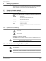
2.1
Signal words and symbols
2.1.1
Classification and meaning of signal words
The danger level – that is, the severity and probability of danger – is indicated by
the signal words listed below. Non-observance may lead to the consequences indicated:
2.1.2
DANGER!
Imminent danger!
May cause danger to life or serious bodily injury!
WARNING!
Dangerous situation!
May cause serious bodily harm.
CAUTION!
May cause dangerous situations!
May cause light injuries!
NOTE!
Possibly harmful situation!
May cause damage to the product or to objects in the immediate vicinity of
the product!
Symbols and their meaning
The symbols listed below indicate the nature and origin of the danger.
General danger
Electrical voltage
Example for an indication of danger
The example below illustrates the appearance and form of danger warnings in our
documents.
DANGER!
2.1.3
External voltage
Disconnect the module from the power supply.
Classification and meaning of additional symbols
Tips and information.
Refers to extremely important or critical decisions to be taken into account before continuing the work.
6
Siemens Building Technologies
Fire & Security Products
007995_a_en_--.doc
04.2004
Safety regulations
2.2
Safety-relevant working instructions
Country-specific standards
The products are developed and produced in compliance with the relevant international and European safety standards. Should additional country-specific, local
safety standards or regulations concerning project planning, installation, operation
and disposal of the product apply in the place of operation, then these standards or
regulations must also be taken into account in addition to the safety regulations
mentioned in the product documentation.
Please especially consider the following instructions:
Do not open the device!.
If any tools or accessories such as ladders are required, safe and suitable devices must be used.
Prevention of spurious tripping of the remote transmission must be assured.
Inform the alarm and fault receiving stations connected to the system (e.g. fire
brigade) before carrying out the tests.
Activate fire control installations for test purposes only when you are sure that no
damage will be caused.
7
Siemens Building Technologies
Fire & Security Products
007995_a_en_--.doc
04.2004
System overview
3
System overview
3.1
General
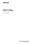
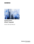
The fire detection system consists of the following modules:
Detectors (detection)
Control unit (evaluation)
Alarm devices (alarming)
Detection
Evaluation
Detector zone
Manual call point zone
Line 1
Line 2
Fire control installations
1
Mixed zone
Alarming
2
3
8888
4
Line 3
Alarm devices
Remote transmission Alarm
Remote transmission Fault
Detector zone
Line x
Supply
115/230VAC
Fig. 1
Setup of a fire detection system
Detectors
With detectors, we distinguish between automatic detectors and manual call points.
Automatic detectors monitor a room and automatically trigger alarm in case of fire.
Depending on the type, automatic detectors may react on smoke, flames, or temperature.
Manual call points must always be actuated by a person.
Control unit
All detectors and alarm devices are connected to the fire detection control unit. If a
detector gives alarm, this alarm signal is transmitted to the control unit. The control
unit decides how the alarm shall be processed. This also applies for fault signals.
The processing of alarms and faults differs from one control unit type to the next. It
is e.g. possible to automatically alert the fire brigade, or to activate signal horns.
Alarm devices
Alarm devices only come into operation in case of alarm. In case of alarm, the signal horns and flash-lights are activated via control lines. In addition, it is possible to
transmit the alarm to an external receiving station (e.g. fire brigade) via a remote
transmission device (RT). In case of fault, it is also possible to inform an external
receiving station.
8
Siemens Building Technologies
Fire & Security Products
007995_a_en_--.doc
04.2004
System overview
3.2
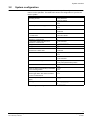
System configuration
Each fire detection system is configured individually. The configuration has an influence on the operation. The table below shows the configuration of your fire detection system.
Parameters
Operating access
Functions and configuration
via password
via key switch
Remote transmission of alarms
yes
no
Alarm sequence involving present staff
yes
no
Switchover from 'Manned' to 'Unmanned'
automatic
manual
automatic switchover time from 'Manned'
indicate
to ''Unmanned''
do not indicate
1. automatic switchover time from
18:00
'Manned' to ''Unmanned''
_____________
2. automatic switchover time from
not activated
'Manned' to ''Unmanned''
_____________
Delay period V1
____ minutes
Delay period V2
____ minutes
Switchover
automatic
summer time / winter time
manual
Remote transmission of faults
yes
no
Function Evacuate
activated
not activated
Access to Acknowledge
always possible
only with password/key switch
Faults must be reset
yes
no
Faults are always immediately transmitted
yes
to the receiving station
no
yes
Manual call points in mixed detector
no
zones trigger alarm also when the detector zone is switched off
Maximum operating time without mains
______ h
supply
Building plan handed over
on: __________
by: _________
Tab. 1
System configuration
9
Siemens Building Technologies
Fire & Security Products
007995_a_en_--.doc
04.2004
Structure and function
4
Structure and function
This chapter describes the setup and function of the fire detection control unit. It
provides the reader with an overview of the possibilities offered by the fire detection control unit. An exact description of the different procedures is included in the
sections 'Operation' and 'Maintenance'.
4.1
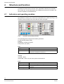
Indicators and operating modules
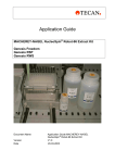
1
2
3
Zone keys
9999
4
Numerical keys
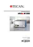
Fig. 2
Zone LEDs
General keys
General LEDs
General LEDs
General keys
The figure below shows the indicators and operating modules. Depending on the
type (number of zones), your control units comprises more or fewer zone keys. The
function of the zone keys is the same with all control unit types.
Indicator module
Indicators and operating modules
The operating panel comprises the following elements:
Light emitting diodes (LED)
Keys
Indicator modules (on option)
Key switch (on option)
LED
Designation
General LEDs
Zone LEDs
Tab. 2
Function
Indicate the status of the entire system.
Indicate the status of the individual zones. One red and one
yellow LED is allocated to each zone.
Function of the LEDs
General:
red LED = alarm
yellow LED = fault, or a part of the system is switched off
Keys
Designation
General keys
Zone keys
Function
General entries, e.g. Acknowledge
Allocate selected functions to the zone; one key is allocated to
each zone
Entry of numeric values
Numeric keys
Tab. 3
Function of the keys
10
Siemens Building Technologies
Fire & Security Products
007995_a_en_--.doc
04.2004
Structure and function
Indicator module
The indicator module is optional and is possibly not equipped yet. The operation
thus differs largely and is mentioned in this manual in the corresponding sections.
Key switch
The key switch is optional and is possibly not equipped yet. It serves for enabling
operation and has the same function as the password (see section 'Enabling operating level 2').
4.2
Function
4.2.1
The most important functions
Function levels
The fire detection control unit is secured against unauthorized manipulation by the
following operating levels:
Operating level 1: operation always possible
Operating level 2: control panel only possible with password or key switch
Operating level 3: operation only possible for the service technician
On operating level 1, only the most important commands in case of alarm can be
issued. All other commands are only accessible on operating level 2.
Power supply
The fire detection control unit is always connected to the power supply system. In
case of a mains failure the control unit is fed from the built-in batteries. Battery operation in case of mains failure is limited.
4.2.2
Detector zones
In the fire detection system, several detectors are always combined in a so-called
detector zone. Depending on the version, the control unit monitors 2, 4, 8, 12 or 24
detector zones.
Up to 32 detectors can be connected to one detector zone. In case of fire, only the
detector zone of the alarming detector is indicated on the control unit. It is thus important to know where the detectors of the individual detector zones are located.
The service technician has handed over a building plan to you, in which the allocation of the detectors to the detector zones is indicated.
11
Siemens Building Technologies
Fire & Security Products
007995_a_en_--.doc
04.2004
Structure and function
4.2.3
Operating modes
The fire detection control unit has the following mode of operations:
'Unmanned'
This operating mode must be set when no instructed staff is present. In case of
alarm or fault, remote transmission (e.g. to the fire brigade) is activated immediately.
'Manned'
In this operating mode instructed staff is present, who is involved in the process
in case of alarm or fault. In this operating mode, an alarm or fault signal activates the remote transmission (e.g. to the fire brigade) only after the expiry of a
defined period of time.
Manual switchover between 'Manned' and 'Unmanned'
The switchover between the operating modes 'Manned' and 'Unmanned' may always be performed manually.
Automatic switchover between 'Manned' and 'Unmanned'
With fire detection system with an indicator module, automatic switchover is possible. At maximum two switchover times may be defined.
Automatic switchover between summer time and winter time
With fire detection systems with an indicator module, switching over between
summer time and winter time can be effected automatically.
12
Siemens Building Technologies
Fire & Security Products
007995_a_en_--.doc
04.2004
Structure and function
4.2.4
Alarms
An alarm is triggered when:
a manual call point has been activated,
an automatic detector has detected a fire.
The process in case of alarm depends on:
the operating mode set ('Manned' or 'Unmanned');
the zone type selected (internal, via timer V1 and V2 or direct)
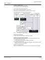
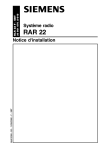
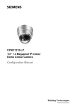
The following figure shows the processing of alarms:
Zone type ‘internal’
Zone type ‘via timer V1/V2’
ALARM
ALARM
fire detector zone
fire detector zone
mode ‘manned’
mode ‘unmanned’
ALARM
no fire zone
mode ‘manned’
no influence
state ‘ALARM 0’
Zone type ‘direct’
ALARM
manual call point zone
mode ‘manned’
no influence
state ‘ALARM 1’
•
•
•
•
• buzzer activated
• sounders activated
• zone output activated
buzzer activated (continuous)
sounders activated
zone output activated
start timer ‘V1’
‘V1’
V1 expired ?
acknowledged ?
Start timer ‘V2’
minor incident ?
fire ?
Decision
• activate next call point
or
• press key
‘cancel alarm delay’
V2 expired ?
state ‘ALARM 2’
Reset
Fig. 3
•
•
•
Buzzer & sounders (re-) activated
control lines(re-) activated
contact RT-Alarm activated
Flow diagram in case of alarm
Process: Zone type direct
In case of alarm, the fire brigade is called up immediately.
Process: Zone type via timer V1 and V2
With this zone type, the process depends on the operating mode set. As a rule:
in operating mode 'Unmanned'
In case of alarm, the fire brigade is called up immediately.
in operating mode 'Manned'
During V1 the staff may acknowledge the alarm. During V2 the staff may check
whether it is a real fire or false alarm.
Process: Zone type internal
Alarm is only indicated on the control unit, it is not transmitted to the fire brigade.
13
Siemens Building Technologies
Fire & Security Products
007995_a_en_--.doc
04.2004
Structure and function
4.2.5
Faults
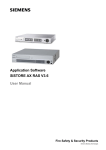
The fire detection control unit includes a comprehensive self-monitoring functionality. When the control unit detects an error in the system (e.g. a detector is removed), this is signaled as fault. Faults are normally transmitted to a receiving station. Faults should always be remedied as quickly as possible.
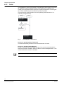
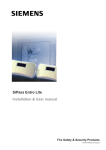
The process with a fault depends on the set operating mode 'Manned' or 'Unmanned' (see figure below).
FAULT
FAULT
mode ‘manned’
mode ‘unmanned’
state ’ FAULT’
• buzzer is activated
• start timer ‘V1’
V1 expired?
‘V1’
Acknowledged?
local FAULT
Remains until fault is
remedied or reseted
state ‘RT-FAULT’
• buzzer is activated
Fig. 4
Flow diagram in case of fault
Process in operating mode 'Unmanned'
The fault automatically activates the remote transmission for faults.
Process in operating mode 'Manned'
During V1 the staff may acknowledge the fault. The control unit will indicate the
fault until it has been remedied. When the fault is not acknowledged within V1, the
remote transmission function is activated.
Faults are possibly always immediately transmitted to the receiving station (see section 'Configuration'.
14
Siemens Building Technologies
Fire & Security Products
007995_a_en_--.doc
04.2004
Structure and function
4.2.6
Indicator module (on option)
The indicator module is optional and possibly not equipped in your system.
The indicator module can display the following information:
Number of registered alarms (alarm counter)
Expiry of the delay periods V1 and V2 in case of alarm
Time
Events with date and time, e.g. fault (recallable event memory)
4.2.7
Maintenance possibilities
Fire detection systems must be serviced regularly. Only this way can it be ensured
that the system works properly in case of emergency. For this reason, regularly
perform the following maintenance work:
Test LED on the control unit
Test detectors
Test fire alarm devices such as horns or flash-lights
Test remote transmission
Check alarm organization
15
Siemens Building Technologies
Fire & Security Products
007995_a_en_--.doc
04.2004
Operation
5
Operation
5.1
Normal operation
In normal operation, the following LED light up:
'System ON'
'Mode Manned' (if the control unit is in operating mode 'Manned' ist)
5.2
Operating level 2 enabled
General
Normally the fire detection control unit is blocked for operation. Operation (operating level 2) is enabled either by entering the password or by means of the key.
Password
To enable operating level 2 with the password, proceed as follows:
1. Enter the password using the numeric keys.
The LED 'Operating access' lights up and the operation is enabled.
2. To block the operating level 2 again, you will have to wait. The operating level 2
is blocked again automatically 3 minutes after the last input.
The LED 'Operating access' no longer lights up.
Key
To enable operating level 2 with the key, proceed as follows:
1. Insert the key in the lock and turn it clockwise by 90°.
The LED 'Operating access' lights up and the operation is enabled.
2. To block operating level 2 again, take the key from the lock.
The LED 'Operating access' no longer lights up.
16
Siemens Building Technologies
Fire & Security Products
007995_a_en_--.doc
04.2004
Operation
5.3
Set operating mode 'Manned'/'Unmanned'
General
You can recognize the set operating mode on the LED 'Manned'.
LED 'Manned'
On
Off
Operating mode
'Manned'
'Unmanned'
When instructed persons are in the building, the operating mode 'Manned' should
be set.
For this reason the first instructed person entering the building should set the fire
detection control unit to operating mode 'Manned'. The other way round, the instructed person who is the last to leave the building should set the fire detection
control unit to operating mode 'Unmanned'.
Procedure
To switch between the operating modes 'Manned' and 'Unmanned', proceed as follows:
1. Enable the operating level 2 (password or key).
1. Press the key 'Manned/Unmanned'.
2. Check the setting by means of the LED 'Manned'.
Note on control units with an indicator module
The automatic switchover between the operating modes 'Manned' and 'Unmanned' depends on the set configuration.
When switching from 'Unmanned' to 'Manned', it is possible to have the next
switchover time from 'Manned' to 'Unmanned' indicated (e.g. 18:00; see table
'Configuration').
17
Siemens Building Technologies
Fire & Security Products
007995_a_en_--.doc
04.2004
Operation
5.4
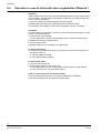
Operation in case of alarm with alarm organization ('Manned')
Important
Alarms always require the quick and controlled intervention of the persons present.
For this reason, read this section thoroughly to make sure you make the right decisions in case of emergency.
In case of emergency the following documents are needed:
Building plan with allocation of the detectors to the detector zones
Checklist for the operation of the control unit (please copy the next page)
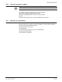
Procedure
In case of alarm the LED 'Alarm' and the red zone LED are flashing rapidly. In case
of alarm, proceed as follows:
1. Press the key 'Acknowledge'.
The LEDs 'Alarm' and the corresponding red zone LED are flashing slowly.
2. Read the fire location (detector zone).
3. Go to the fire location.
4. Decide whether it is an emergency of a false alarm.
In case of emergency
1. Activate the next manual call point or go back to the control unit and press the
key 'Alarm delay' off.
The fire brigade is alerted.
The LED 'RT Alarm' lights up.
In case of false alarm
1. Go back to the control unit.
2. Press the key 'Reset' on the control unit.
The LEDs 'Alarm' and the corresponding red zone LED no longer light up.
The control unit is in normal operation again.
Note on control units with an indicator module
The remaining delay periods V1 and V2 are indicated on the display.
All other indications are overwritten during the alarm.
18
Siemens Building Technologies
Fire & Security Products
007995_a_en_--.doc
04.2004
Operation
Copy this page and keep it ready in case of alarm!
Alarm (red LEDs are
flashing rapidly)
Press red key
Read off fire location
Go to the fire location
Decide!
No fire
Fire
Back to the
control unit
Activate next
manual call
point
F
Press green
key
19
Siemens Building Technologies
Fire & Security Products
007995_a_en_--.doc
04.2004
Operation
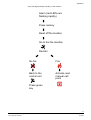
5.5
Activating an evacuation
Overview
It is possible to activate an evacuation without an alarm being triggered by a detector. In this case no alarm message is transmitted to the fire brigade.
Procedure
To activate an evacuation, please proceed as follows:
1. Enable the operating level 2 (password or key).
2. Press the key 'Evacuation'.
The LED 'Evacuation' lights up.
The fire alarm devices (e.g. horns) are activated
3. To cancel the evacuation, press the key 'Evacuation' again.
The LED 'Evacuation' no longer lights up.
The fire alarm devices (e.g. horns) are deactivated
The control unit is in normal operating condition again.
20
Siemens Building Technologies
Fire & Security Products
007995_a_en_--.doc
04.2004
Operation
5.6
Switching off system parts
In certain situations (e.g. renovation work) it may make sense to switch off parts of
a system. When a system part is switched off, the LED 'Part of system OFF' is always on.
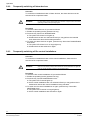
WARNING!
5.6.1
System parts that have been switched off may possibly hamper the correct
recording or processing of alarms or faults! For this reason, always switch these
system parts on again as soon as normal operating conditions are prevailing
again!
Switching off detector zones
Overview
To avoid unintended alarm messages, in exceptional cases detector zones must
be disconnected from the system, i.e. switched off. In which cases a detector zone
shall be switched off depends on the detectors used and the deceptive phenomena
(e.g. smoke or dust).
WARNING!
Detector zones that have been switched off cannot trigger alarms or faults! For
this reason, always switch these detector zones on again as soon as normal
operating conditions are prevailing again!
NOTE!
Manual fire alarm call points may possibly trigger alarm even when the detector
zone is switched off (see section 'Configuration').
Procedure
To switch a detector zone off, proceed as follows:
1. Enable the operating level 2 (password or key).
2. Press the desired detector zone key.
The yellow zone LED lights up.
The zone is now switched off and you can perform the intended work on the
detector zone without an alarm or fault being remotely transmitted.
3. To switch the zone on again, press the desired detector zone key twice.
The yellow zone LED no longer lights up.
The zone is switched on again.
21
Siemens Building Technologies
Fire & Security Products
007995_a_en_--.doc
04.2004
Operation
5.6.2
Temporarily switching off alarm devices
Overview
To avoid the unintended activation of alarm devices, the alarm devices must be
switched off in exceptional cases.
WARNING!
Alarm devices that have been switched off are not activated in case of alarm!
For this reason, always switch these alarm devices on again as soon as normal
operating conditions are prevailing again!
Procedure
To switch the alarm devices off, proceed as follows:
1. Enable the operating level 2 (password or key).
2. Press the key 'Alarm horn Disable/Enable'
The yellow LED 'Alarm horn' lights up.
All alarm devices are now switched off and you may perform the intended
work without the alarm devices being activated.
3. To switch the alarm devices on again, press the key 'Alarm horn Disable/Enable'
three times.
The yellow LED 'Alarm horn' no longer lights up.
All alarm devices are switched on again.
5.6.3
Temporarily switching off fire control installations
Overview
To avoid the unintended activation of fire control installations, these must be
switched off in exceptional cases.
WARNING!
Fire control installations that have been switched off are not activated in case of
alarm! For this reason, always switch these fire control installations on again as
soon as normal operating conditions are prevailing again!
Procedure
To switch the fire control installations off, proceed as follows:
1. Enable the operating level 2 (password or key).
2. Press the key 'Control Disable/Enable' twice.'
The yellow LED 'Controls' lights up.
All fire control installations are now switched off and you may perform the intended work without the control installations being activated.
3. To switch the fire control installations on again, press the key 'Control Disable/Enable' twice.
The yellow LED 'Controls' no longer lights up.
All fire control installations are switched on again.
22
Siemens Building Technologies
Fire & Security Products
007995_a_en_--.doc
04.2004
Operation
5.6.4
Switching fire control installations and alarm devices temporarily off
Overview
To avoid the unintended activation of fire control installations and alarm devices,
these must be switched off in exceptional cases.
WARNING!
Fire control installations and alarm devices that have been switched off are not
activated in case of alarm! For this reason, always switch these fire control
installations and alarm devices on again as soon as normal operating conditions
are prevailing again!
Procedure
To switch the fire control installations off, proceed as follows:
1. Enable the operating level 2 (password or key).
2. Press the key 'Control Disable/Enable' three times.
The yellow LED 'Alarm horn' and 'Controls' light up.
The fire control installations and alarm devices are now switched off and you
may perform the intended work without the control installations being activated.
3. To switch the fire control installations and alarm devices on again, press the key
'Control Disable/Enable' once.
The yellow LED 'Alarm horn' and 'Controls' no longer light up.
The fire control installations are switched on again.
5.6.5
Temporarily blocking remote transmission of faults
Overview
If in exceptional cases faults shall not be remotely transmitted, the remote transmission of faults must be blocked.
WARNING!
Remote transmission functions that have been blocked are not activated in case
of a fault! For this reason, always enable blocked remote transmission functions
again as soon as normal operating conditions are prevailing again!
Procedure
To block the remote transmission of faults, please proceed as follows:
1. Enable the operating level 2 (password or key).
2. Press the key 'RT-FAULT Disable/Enable'.
The yellow LED 'RT-FAULT' lights up.
The remote transmission of faults is now blocked and you can carry out the intended work.
3. To enable the remote transmission of faults again, press the key 'RT-FAULT
Disable/Enable'' three times.
The yellow LED 'RT-FAULT' no longer lights up.
The remote transmission of faults is enabled again.
23
Siemens Building Technologies
Fire & Security Products
007995_a_en_--.doc
04.2004
Operation
5.6.6
Temporarily blocking remote transmission of alarms
Overview
If in exceptional cases alarms shall not be remotely transmitted, the remote transmission of alarms must be blocked.
WARNING!
Remote transmission functions that have been blocked are not activated in case
of an alarm! For this reason, always enable blocked remote transmission functions again as soon as normal operating conditions are prevailing again!
Procedure
To block the remote transmission of alarms, please proceed as follows:
1. Enable the operating level 2 (password or key).
2. Press the key 'RT-ALARM Disable/Enable' twice.
The yellow LED 'RT-ALARM' lights up.
The remote transmission of alarms is now blocked and you can carry out the
intended work.
3. To switch the remote transmission of alarms on again, press the key 'RT-Alarm
Disable/Enable' twice.
The yellow LED 'RT-ALARM' no longer lights up.
The remote transmission of alarms is enabled again.
5.6.7
Temporarily blocking remote transmission of alarms & faults
Overview
If in exceptional cases alarms or faults shall not be remotely transmitted, the remote transmission of alarms and faults must be blocked.
WARNING!
Remote transmission functions that have been blocked are not activated in case
of an alarm or fault! For this reason, always enable blocked remote transmission
functions again as soon as normal operating conditions are prevailing again!
Procedure
To block the remote transmission, please proceed as follows:
1. Enable the operating level 2 (password or key).
2. Press the key 'RT-ALARM Disable/Enable' three times.
The yellow LEDs 'RT-FAULT' and 'RT-ALARM' light up.
The remote transmission of alarms and faults is now blocked and you can
carry out the intended work.
3. To switch the remote transmission on again, press the key 'RT-ALARM Disable/Enable' once.
The yellow LED 'RT-FAULT' and 'RT-ALARM' no longer light up.
The remote transmission of alarms and faults is enabled again.
24
Siemens Building Technologies
Fire & Security Products
007995_a_en_--.doc
04.2004
Operation
5.7
Polling event memory
Overview
This function is only available with control units with an indicator module.
The event memory records event with date and time. These event can be polled at
any time. Each event has an event number. This number is displayed on the indicator module (e.g. E.012.). The most recent event has the lowest number (E.001.).
The event is indicated by means of the LED. An alarm on zone 4, for example, is
indicated by the red zone LED 4.
Procedure
To poll the event memory, proceed as follows:
1. Enable the operating level 2 (password or key).
2. Keep the key 'Acknowledge' pressed and enter the code '1122' with the numerical keys.
The indicator module displays 'E.001.' (most recent event).
The type of event is indicated by the LEDs (see table below).
3. Poll the year of the event with the numeric key '1', the month with the key '2' and
the time with the key '3'.
The indicator module displays e.g. '2004'
4. To indicate the next event, press the key 'Reset'.
The indicator module displays 'E.002'.
To get back to the most recent event, press the numeric key '4'.
The indicator module displays 'E.001.'
5. To quit the event memory, press the numeric key 'Acknowledge'.
The system is in normal operating condition again.
You will quit the event memory automatically when you do not enter any data for
more than one minute.
Indication
Signification
Red zone LED
Alarm of the corresponding zone
'Remote transmission'
Remote transmission activated
'Part of system OFF'
System part has been out of service
'Fault'
A fault has occurred in the system
'Evacuation'
Evacuation has been activated
Tab. 4
Meaning of the LED display
25
Siemens Building Technologies
Fire & Security Products
007995_a_en_--.doc
04.2004
Operation
5.8
Setting date and time
Overview
This function is only available with control units with an indicator module.
Control units with an indicator module are equipped with an integrated clock. In
countries in which the Central European Summertime is valid, this clock automatically switches between summer and winter time. In all other countries the settings
must be made manually.
The clock must also be set when the fire detection control unit has been disconnected from the power supply system for a longer period of time.
Procedure
To set the date and time, proceed as follows:
1. Enable the operating level 2 (password or key).
2. Keep the key 'Reset' pressed and enter the code '4233' with the numerical keys.
3. Acknowledge the entry by pressing the key 'Acknowledge'.
The LEDs 'Manned' and 'Operating access' are flashing.
The indicator module displays '1_.xx' (xx = year)
4. Set the desired year with the numerical keys '1' and '2'.
5. Acknowledge the entry by pressing the zone key '1'.
6. Press the key 'Reset'.
The indicator module displays '2_.xx' (xx = year)
7. Repeat the steps 4 to 6, thus setting the day, the hours and the minutes.
8. Exit the settings with the numerical key '4'.
The settings have been stored.
The system is in normal operating condition again.
26
Siemens Building Technologies
Fire & Security Products
007995_a_en_--.doc
04.2004
Maintenance
6
Maintenance
6.1
Important notes
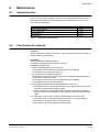
Only a well-serviced fire detection system remains functional in case of emergency. For this reason, regularly perform the recommended maintenance work or
have them performed by a service technician (see table below). At any rate, observe the local regulations.
Maintenance work
Check detector network
Check control unit
Simulate alarm
Simulate fault
Tab. 5
Maintenance work intervals
6.2
Interval
annually
annually
annually
annually
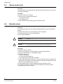
Check detector network
Overview
Check the detector network once a year. In this way the functionality of the fire detection system can be ensured.
Procedure
Check the detector network as follows:
1. Enable the operating level 2 (password or key).
2. Either: for detector test
Press the desired detector zone key twice.
The yellow zone LED and the LED 'Detector test' are flashing.
The LED Part of system OFF lights up.
Or: for detector test including walk test:
Press the desired detector zone key twice, then immediately afterwards the numerical key '4' during 2 seconds.
The yellow zone LED and the LED 'Detector test' are flashing.
The LED 'Part of system OFF' lights up.
3. Successively activate an alarm with all detectors in this zone.
The red zone LED on the control unit lights up for approximately 10 seconds.
No alarm is transmitted to the fire brigade.
When under Item 2 you have activated the detector test including walk test,
the alarm devices are activated for a short period of time with each alarm activation.
4. To switch the zone on again, press the desired detector zone key once.
The yellow zone LED and the LED 'Detector test' are no longer flashing.
The LED 'Part of system OFF' no longer lights up.
The system is in normal operating condition again.
27
Siemens Building Technologies
Fire & Security Products
007995_a_en_--.doc
04.2004
Maintenance
6.3
Check control unit
Overview
This test intends to check whether the optical and acoustic elements of the control
unit function faultlessly.
Procedure
Check the control unit as follows:
1. Press the key 'Lamp test/Sounder test'
The buzzer sounds.
All LEDs light up.
2. Check whether all LEDs light up and the buzzer sounds.
6.4
Simulate alarm
Overview
By simulating an alarm you can check the following functions of the fire detection
system:
Remote transmission (e.g. transmission to the fire brigade)
Alarming devices (e.g. horns and flashlights).
Fire control installations
WARNING!
Before simulating an alarm, inform the fire brigade to avoid an unnecessary
turning out.
WARNING!
Activate the fire control installations only when you are sure that no damage will
occur. When you are not sure, switch the fire control installations off.
Procedure
Simulate an alarm as follows:
1. Inform accordingly (e.g. the fire brigade) on the pending simulation.
2. Press the numerical key '1' and keep it pressed.
3. Press the zone key '1'.
Alarm is simulated.
The red zone LED lights up.
The alarm sequence has been activated.
4. Check whether the alarm sequence is correct. Zones with manual call points will
trigger alarm immediately. Zones with automatic detectors will trigger alarm after
the expiry of the delay periods V1 and V2.
5. Check whether the fire control installations have responded correctly.
6. To finish the simulation, press the key 'Acknowledge', then the key 'Reset'.
7. Repeat steps 2 to 5 for all zones.
28
Siemens Building Technologies
Fire & Security Products
007995_a_en_--.doc
04.2004
Maintenance
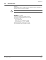
6.5
Simulate fault
Overview
By simulating a fault it is possible to check the remote transmission equipment for
faults (e.g. transmission to the fire brigade).
WARNING!
Before simulating a fault, inform accordingly to avoid an unnecessary turning
out.
Procedure
Simulate a fault as follows:
1. Inform accordingly on the pending simulation.
2. Press the numerical key '2' and keep it pressed.
3. Press the zone key '1'.
A fault is simulated.
The yellow zone LED is flashing rapidly.
The fault sequence has been activated.
4. Check whether the fault sequence is correct.
5. To finish the simulation, press the key 'Reset'.
29
Siemens Building Technologies
Fire & Security Products
007995_a_en_--.doc
04.2004
Troubleshooting
7
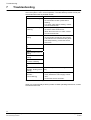
Troubleshooting
This section provides you with information in case of a system disturbance, or
when the system is not in normal operation. The table below provides a list of possible faults with notes on possible causes.
Fault
LED 'Fault' is flashing
Cause/Remedy
Fault in the system
1. Check whether another yellow LED is
flashing.
2. If no other yellow LED is flashing, contact
the service technician.
LED 'Fault power supply' Fault in the power supply
is flashing
1. Check the external mains fuse.
2. When the mains fuse is in order, contact
the service technician.
Yellow zone LED is
Fault in a zone
flashing
3. Check whether all detectors are inserted.
4. If all detectors are inserted and the yellow
LED keeps flashing, contact the service
technician.
LED 'Earth fault' is flash- Contact the service technician
ing
LED 'Fault control unit' is
flashing
LED 'Fault alarm horn' is
flashing
LED 'Fault controls' is
flashing
LED 'Remote transmission fault' is flashing
LED 'RT alarm' is flashing
Clock not set (see section 'Setting date and
The indicator module
indicates: '88.88' (point is time')
flashing)
Fault in the power supply
The indicator module
5. Verify whether the mains supply is availindicates: '.'
able.
(point is flashing)
6. Contact the service technician.
Tab. 6
Troubleshooting
When you cannot remedy a fault by means of these operating instructions, contact
the service technician.
30
Siemens Building Technologies
Fire & Security Products
007995_a_en_--.doc
04.2004
Siemens Building Technologies AG
Alte Landstr. 411
CH-8708 Männedorf
Tel. +41 1 - 922 6111
Fax +41 1 - 922 6450
www.sbt.siemens.com
Document no.
007995_a_en_--
Edition
04.2004
Manual xx
Section x