1
MAKING MODERN LIVING POSSIBLE
Programming Guide
VLT® HVAC Drive
VLT® HVAC Drive Programming Guide
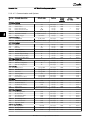
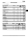
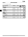
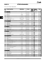
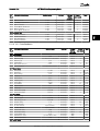
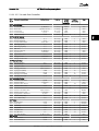
Contents
Contents
1 Introduction
3
1.1.1 Copyright, Limitation of Liability and Revision Rights
3
1.1.2 Approvals
3
1.1.3 Symbols
3
1.1.4 Abbreviations
4
1.1.6 Definitions
4
2 How to Programme
9
2.1 Local Control Panel
9
2.1.1 How to Operate Graphical LCP (GLCP)
9
2.1.2 How to Operate Numeric LCP (NLCP)
12
2.1.5 Quick Menu Mode
14
2.1.6 Function Set-ups
16
2.1.7 Main Menu Mode
19
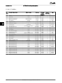
3 Parameter Description
22
3.1 Parameter Selection
22
3.1.1 Main Menu Structure
22
3.2 Main Menu - Operation and Display - Group 0
23
3.3 Main Menu - Load and Motor - Group 1
35
3.4 Main Menu - Brakes - Group 2
49
3.5 Main Menu - Reference/Ramps - Group 3
52
3.6 Main Menu - Limits/Warnings - Group 4
58
3.7 Main Menu - Digital In/Out - Group 5
62
3.7.4 5-13 Terminal 29 Digital Input
65
3.8 Main Menu - Analog In/Out - Group 6
75
3.9 Main Menu - Communications and Options - Group 8
82
3.10 Main Menu - Profibus - Group 9
89
3.11 Main Menu - CAN Fieldbus - Group 10
94
3.12 Main Menu - LonWorks - Group 11
97
3.13 Main Menu - Smart Logic - Group 13
98
3.14 Main Menu - Special Functions -Group 14
109
3.14.6 14-50 RFI Filter
113
3.15 Main Menu - Drive Information - Group 15
115
3.16 Main Menu - Data Readouts - Group 16
120
3.17 Main Menu - Data Readouts 2 - Group 18
127
3.18 Main Menu - FC Closed Loop - Group 20
129
3.19 Main Menu - Extended Closed Loop - Group 21
140
3.20 Main Menu - Application Functions - Group 22
147
3.21 Main Menu - Time-based Functions - Group 23
159
MG11CD02 - VLT® is a registered Danfoss trademark
1
VLT® HVAC Drive Programming Guide
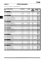
Contents
3.22 Main Menu - Application Functions 2 - Group 24
169
3.23 Main Menu - Cascade Controller - Group 25
175
3.24 Main Menu - Analog I/O Option MCB 109 - Group 26
184
4 Troubleshooting
191
4.1 Troubleshooting
191
4.1.1 Alarm Words
195
4.1.2 Warning Words
196
4.1.3 Extended Status Words
197
4.1.4 Fault Messages
198
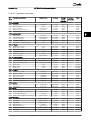
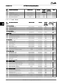
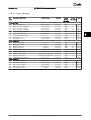
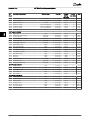
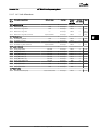
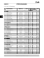
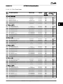
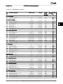
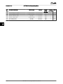
5 Parameter Lists
204
5.1 Parameter Options
204
5.1.1 Default settings
204
5.1.2 0-** Operation and Display
205
5.1.3 1-** Load / Motor
206
5.1.4 2-** Brakes
207
5.1.5 3-** Reference / Ramps
208
5.1.6 4-** Limits / Warnings
209
5.1.7 5-** Digital In / Out
210
5.1.8 6-** Analog In / Out
211
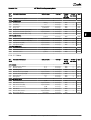
5.1.9 8-** Communication and Options
212
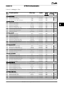
5.1.10 9-** Profibus
214
5.1.11 10-** CAN Fieldbus
215
5.1.12 11-** LonWorks
215
5.1.13 13-** Smart Logic Controller
216
5.1.14 14-** Special Functions
217
5.1.15 15-** Drive Information
218
5.1.16 16-** Data Readouts
219
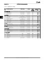
5.1.17 18-** Info & Readouts
221
5.1.18 20-** FC Closed Loop
222
5.1.19 21-** Ext. Closed Loop
223
5.1.20 22-** Application Functions
225
5.1.21 23-** Time Based Funtions
227
5.1.22 24-** Application Functions 2
228
5.1.23 25-** Cascade Pack Controller
229
5.1.24 26-** Analog I / O Option MCB 109
230
Index
2
231
MG11CD02 - VLT® is a registered Danfoss trademark
VLT® HVAC Drive Programming Guide
Introduction
1 1
1 Introduction
VLT®
HVAC Drive
FC 100 Series
equipment, loss of computer programs, loss of data, the
costs to substitute these, or any claims by third parties.
Danfoss reserves the right to revise this publication at any
time and to make changes to its contents without prior
notice or any obligation to notify former or present users
of such revisions or changes.
1.1.2 Approvals
This guide can be used with all
VLT® HVAC Drive frequency
converters with software version
3.7x.
The actual software version
number can be read from
15-43 Software Version.
1.1.1 Copyright, Limitation of Liability and
Revision Rights
This publication contains information proprietary to
Danfoss. By accepting and using this manual the user
agrees that the information contained herein will be used
solely for operating equipment from Danfoss or equipment
from other vendors provided that such equipment is
intended for communication with Danfoss equipment over
a serial communication link. This publication is protected
under the Copyright laws of Denmark and most other
countries.
Danfoss does not warrant that a software program
produced according to the guidelines provided in this
manual will function properly in every physical, hardware
or software environment.
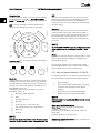
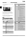
1.1.3 Symbols
Symbols used in this guide.
NOTE
Indicates something to be noted by the reader.
CAUTION
Indicates a potentially hazardous situation which, if not
avoided, may result in minor or moderate injury or
equipment damage.
WARNING
Indicates a potentially hazardous situation which, if not
avoided, could result in death or serious injury.
*
Indicates default setting
Although Danfoss has tested and reviewed the documentation within this manual, Danfoss makes no warranty or
representation, neither expressed nor implied, with respect
to this documentation, including its quality, performance,
or fitness for a particular purpose.
In no event shall Danfoss be liable for direct, indirect,
special, incidental, or consequential damages arising out of
the use, or the inability to use information contained in
this manual, even if advised of the possibility of such
damages. In particular, Danfoss is not responsible for any
costs, including but not limited to those incurred as a
result of lost profits or revenue, loss or damage of
MG11CD02 - VLT® is a registered Danfoss trademark
3
1 1
VLT® HVAC Drive Programming Guide
Introduction
1.1.4 Abbreviations
Alternating current
AC
American wire gauge
AWG
Ampere/AMP
A
Automatic Motor Adaptation
AMA
Current limit
ILIM
Degrees Celsius
°C
Direct current
DC
Drive Dependent
D-TYPE
Electro Magnetic Compatibility
EMC
Electronic Thermal Relay
ETR
frequency converter
FC
Gram
g
Hertz
Hz
Horsepower
hp
Kilohertz
kHz
Local Control Panel
LCP
Meter
m
Millihenry Inductance
mH
Milliampere
mA
Millisecond
ms
Minute
min
Motion Control Tool
MCT
Nanofarad
nF
Newton Meters
Nm
Nominal motor current
IM,N
Nominal motor frequency
fM,N
Nominal motor power
PM,N
Nominal motor voltage
UM,N
Permanent Magnet motor
PM motor
Protective Extra Low Voltage
PELV
Printed Circuit Board
PCB
Rated Inverter Output Current
IINV
Revolutions Per Minute
RPM
Regenerative terminals
Regen
Second
sec.
Synchronous Motor Speed
ns
Torque limit
TLIM
Volts
V
The maximum output current
IVLT,MAX
The rated output current supplied by the
frequency converter
IVLT,N
1.1.5 Available Literature for VLT® HVAC
Drive
4
-
Design Guide MG.11.Bx.yy entails all technical
information about the frequency converter and
customer design and applications.
-
Programming Guide MG.11.Cx.yy provides
information on how to programme and includes
complete parameter descriptions.
-
Application Note, Temperature Derating Guide,
MN.11.Ax.yy
-
PC-based Configuration Tool MCT 10, MG.10.Ax.yy
enables the user to configure the frequency
converter from a Windows™ based PC
environment.
-
Danfoss VLT® Energy Box software at
www.danfoss.com/BusinessAreas/DrivesSolutions
then choose PC Software Download
-
Operating Instructions VLT® HVAC Drive BACnet,
MG.11.Dx.yy
-
Operating Instructions VLT® HVAC Drive Metasys,
MG.11.Gx.yy
-
Operating Instructions VLT® HVAC Drive FLN,
MG.11.Zx.yy
x = Revision number
yy = Language code
Danfoss technical literature is available in print from your
local Danfoss Sales Office or online at:
www.danfoss.com/BusinessAreas/DrivesSolutions/Documentations/Technical+Documentation.htm
1.1.6 Definitions
Frequency converter:
IVLT,MAX
Maximum output current.
IVLT,N
Rated output current supplied by the frequency converter.
UVLT, MAX
Maximum output voltage.
Input:
Control command
Start and stop the connected motor by means of LCP and
digital inputs.
Functions are divided into two groups.
Functions in group 1 have higher priority than functions in
group 2.
Group 1
Reset, Coasting stop, Reset and Coasting stop,
Quick-stop, DC braking, Stop and the [OFF] key.
Group 2
Start, Pulse start, Reversing, Start reversing, Jog
and Freeze output
Motor:
Motor Running
Torque generated on output shaft and speed from zero
rpm to max. speed on motor.
fJOG
Motor frequency when the jog function is activated (via
digital terminals).
MG11CD02 - VLT® is a registered Danfoss trademark
VLT® HVAC Drive Programming Guide
Introduction
1 1
Start-disable command
A stop command belonging to the group 1 control
commands - see this group.
fM
Motor frequency.
fMAX
Maximum motor frequency.
Stop command
See Control commands.
fMIN
Minimum motor frequency.
fM,N
Rated motor frequency (nameplate data).
IM
Motor current (actual).
References:
Analog Reference
A signal transmitted to the analog inputs 53 or 54, can be
voltage or current.
IM,N
Rated motor current (nameplate data).
Binary Reference
A signal transmitted to the serial communication port.
nM,N
Rated motor speed (nameplate data).
Preset Reference
A defined preset reference to be set from -100% to +100%
of the reference range. Selection of eight preset references
via the digital terminals.
ns
Synchronous motor speed
Pulse Reference
A pulse frequency signal transmitted to the digital inputs
(terminal 29 or 33).
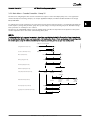
2 × par . 1 − 23 × 60 s
ns =
par . 1 − 39
PM,N
Rated motor power (nameplate data in kW or HP).
RefMAX
Determines the relationship between the reference input
at 100% full scale value (typically 10V, 20mA) and the
resulting reference. The maximum reference value set in
3-03 Maximum Reference.
TM,N
Rated torque (motor).
RefMIN
Determines the relationship between the reference input
at 0% value (typically 0V, 0mA, 4mA) and the resulting
reference. The minimum reference value set in
3-02 Minimum Reference.
UM
Instantaneous motor voltage.
UM,N
Rated motor voltage (nameplate data).
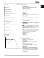
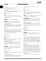
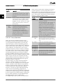
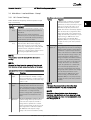
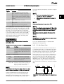
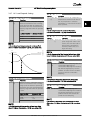
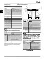
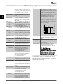
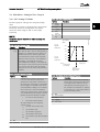
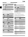
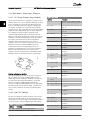
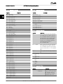
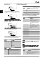
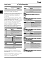
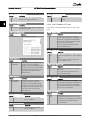
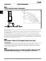
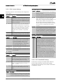
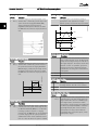
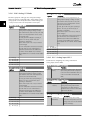
Break-away torque
175ZA078.10
Torque
Pull-out
Miscellaneous:
Analog Inputs
The analog inputs are used for controlling various
functions of the frequency converter.
There are two types of analog inputs:
Current input, 0-20mA and 4-20mA
Voltage input, 0-10V DC ()
Voltage input, -10 - +10V DC (FC 102).
Analog Outputs
The analog outputs can supply a signal of 0-20mA,
4-20mA.
Automatic Motor Adaptation, AMA
AMA algorithm determines the electrical parameters for
the connected motor at standstill.
rpm
ηVLT
The efficiency of the frequency converter is defined as the
ratio between the power output and the power input.
Brake Resistor
The brake resistor is a module capable of absorbing the
brake power generated in regenerative braking. This
regenerative braking power increases the intermediate
circuit voltage and a brake chopper ensures that the
power is transmitted to the brake resistor.
CT Characteristics
Constant torque characteristics used for all applications
such as conveyor belts, displacement pumps and cranes.
MG11CD02 - VLT® is a registered Danfoss trademark
5
1 1
Introduction
VLT® HVAC Drive Programming Guide
Digital Inputs
The digital inputs can be used for controlling various
functions of the frequency converter.
Digital Outputs
The frequency converter features two Solid State outputs
that can supply a 24V DC (max. 40mA) signal.
DSP
Digital Signal Processor.
ETR
Electronic Thermal Relay is a thermal load calculation
based on present load and time. Its purpose is to estimate
the motor temperature.
Hiperface®
Hiperface® is a registered trademark by Stegmann.
Initialising
If initialising is carried out (14-22 Operation Mode), the
frequency converter returns to the default setting.
Intermittent Duty Cycle
An intermittent duty rating refers to a sequence of duty
cycles. Each cycle consists of an on-load and an off-load
period. The operation can be either periodic duty or nonperiodic duty.
LCP
The Local Control Panel makes up a complete interface for
control and programming of the frequency converter. The
control panel is detachable and can be installed up to 3
metres from the frequency converter, i.e. in a front panel
by means of the installation kit option.
lsb
Least significant bit.
msb
Most significant bit.
MCM
Short for Mille Circular Mil, an American measuring unit for
cable cross-section. 1 MCM = 0.5067mm2.
On-line/Off-line Parameters
Changes to on-line parameters are activated immediately
after the data value is changed. Changes to off-line
parameters are not activated until you enter [OK] on the
LCP.
Process PID
The PID control maintains the desired speed, pressure,
temperature, etc. by adjusting the output frequency to
match the varying load.
PCD
Process Control Data
Power Cycle
Switch off the mains until display (LCP) is dark – then turn
power on again.
Pulse Input/Incremental Encoder
An external, digital pulse transmitter used for feeding back
information on motor speed. The encoder is used in
6
applications where great accuracy in speed control is
required.
RCD
Residual Current Device.
Set-up
You can save parameter settings in four Set-ups. Change
between the four parameter Set-ups and edit one Set-up,
while another Set-up is active.
SFAVM
Switching pattern called Stator Flux oriented Asynchronous
Vector Modulation (14-00 Switching Pattern).
Slip Compensation
The frequency converter compensates for the motor slip
by giving the frequency a supplement that follows the
measured motor load keeping the motor speed almost
constant.
Smart Logic Control (SLC)
The SLC is a sequence of user defined actions executed
when the associated user defined events are evaluated as
true by the Smart Logic Controller. (Par. group 13-** Smart
Logic Control (SLC).
STW
Status Word
FC Standard Bus
Includes RS-485 bus with FC protocol or MC protocol. See
8-30 Protocol.
Thermistor
A temperature-dependent resistor placed where the
temperature is to be monitored (frequency converter or
motor).
Trip
A state entered in fault situations, e.g. if the frequency
converter is subject to an over-temperature or when the
frequency converter is protecting the motor, process or
mechanism. Restart is prevented until the cause of the
fault has disappeared and the trip state is cancelled by
activating reset or, in some cases, by being programmed
to reset automatically. Trip may not be used for personal
safety.
Trip Locked
A state entered in fault situations when the frequency
converter is protecting itself and requiring physical
intervention, e.g. if the frequency converter is subject to a
short circuit on the output. A locked trip can only be
cancelled by cutting off mains, removing the cause of the
fault, and reconnecting the frequency converter. Restart is
prevented until the trip state is cancelled by activating
reset or, in some cases, by being programmed to reset
automatically. Trip may not be used for personal safety.
VT Characteristics
Variable torque characteristics used for pumps and fans.
MG11CD02 - VLT® is a registered Danfoss trademark
VLT® HVAC Drive Programming Guide
Introduction
VVCplus
If compared with standard voltage/frequency ratio control,
Voltage Vector Control (VVCplus ) improves the dynamics
and the stability, both when the speed reference is
changed and in relation to the load torque.
60° AVM
Switching pattern called 60° Asynchronous Vector
Modulation (14-00 Switching Pattern).
4.
The earth leakage current exceeds 3.5mA.
5.
Protection against motor overload is not included
in the factory setting. If this function is desired,
set 1-90 Motor Thermal Protection to data value
ETR trip 1 [4] or data value ETR warning 1 [3].
6.
Do not remove the plugs for the motor and
mains supply while the frequency converter is
connected to mains. Check that the mains supply
has been disconnected and that the necessary
time has elapsed before removing motor and
mains plugs.
7.
Please note that the frequency converter has
more voltage sources than L1, L2 and L3, when
load sharing (linking of DC intermediate circuit)
or external 24V DC are installed. Check that all
voltage sources have been disconnected and that
the necessary time has elapsed before
commencing repair work.
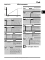
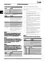
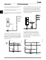
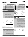
Power Factor
The power factor is the relation between I1 and IRMS.
Power factor =
3 x U x I 1 cos ϕ
3 x U x I RMS
The power factor for 3-phase control:
=
I1
I 1 x cos ϕ1
=
since cos ϕ1 = 1
I RMS
I RMS
The power factor indicates to which extent the frequency
converter imposes a load on the mains supply.
The lower the power factor, the higher the IRMS for the
same kW performance.
I RMS =
I 12 + I 52 + I 72 + .. + I n2
In addition, a high power factor indicates that the different
harmonic currents are low.
The frequency converters' built-in DC coils produce a high
power factor, which minimizes the imposed load on the
mains supply.
WARNING
The voltage of the frequency converter is dangerous
whenever connected to mains. Incorrect installation of the
motor, frequency converter or fieldbus may cause death,
serious personal injury or damage to the equipment.
Consequently, the instructions in this manual, as well as
national and local rules and safety regulations, must be
complied with.
Safety Regulations
1.
The mains supply to the frequency converter
must be disconnected whenever repair work is to
be carried out. Check that the mains supply has
been disconnected and that the necessary time
has elapsed before removing motor and mains
supply plugs.
2.
The [OFF] button on the control panel of the
frequency converter does not disconnect the
mains supply and consequently it must not be
used as a safety switch.
3.
The equipment must be properly earthed, the
user must be protected against supply voltage
and the motor must be protected against
1 1
overload in accordance with applicable national
and local regulations.
Warning against unintended start
1.
The motor can be brought to a stop by means of
digital commands, bus commands, references or
a local stop, while the frequency converter is
connected to mains. If personal safety considerations (e.g. risk of personal injury caused by
contact with moving machine parts following an
unintentional start) make it necessary to ensure
that no unintended start occurs, these stop
functions are not sufficient. In such cases the
mains supply must be disconnected or the Safe
Stop function must be activated.
2.
The motor may start while setting the
parameters. If this means that personal safety
may be compromised (e.g. personal injury caused
by contact with moving machine parts), motor
starting must be prevented, for instance by use
of the Safe Stop function or secure disconnection
of the motor connection.
3.
A motor that has been stopped with the mains
supply connected, may start if faults occur in the
electronics of the frequency converter, through
temporary overload or if a fault in the power
supply grid or motor connection is remedied. If
unintended start must be prevented for personal
safety reasons (e.g. risk of injury caused by
contact with moving machine parts), the normal
stop functions of the frequency converter are not
sufficient. In such cases the mains supply must be
disconnected or the Safe Stop function must be
activated.
4.
Control signals from, or internally within, the
frequency converter may in rare cases be
MG11CD02 - VLT® is a registered Danfoss trademark
7
Introduction
1 1
VLT® HVAC Drive Programming Guide
activated in error, be delayed or fail to occur
entirely. When used in situations where safety is
critical, e.g. when controlling the electromagnetic
brake function of a hoist application, these
control signals must not be relied on exclusively.
WARNING
High Voltage
Touching the electrical parts may be fatal - even after the
equipment has been disconnected from mains.
Also make sure that other voltage inputs have been
disconnected, such as external 24 V DC, load sharing
(linkage of DC intermediate circuit), as well as the motor
connection for kinetic back up.
Systems where frequency converters are installed must, if
necessary, be equipped with additional monitoring and
protective devices according to the valid safety regulations,
e.g law on mechanical tools, regulations for the prevention
of accidents etc. Modifications on the frequency converters
by means of the operating software are allowed.
NOTE
Hazardous situations shall be identified by the machine
builder/ integrator who is responsible for taking necessary
preventive means into consideration. Additional
monitoring and protective devices may be included, always
according to valid national safety regulations, e.g. law on
mechanical tools, regulations for the prevention of
accidents.
Protection Mode
Once a hardware limit on motor current or dc-link voltage
is exceeded the frequency converter will enter “Protection
mode”. “Protection mode” means a change of the PWM
modulation strategy and a low switching frequency to
minimize losses. This continues 10 sec after the last fault
and increases the reliability and the robustness of the
frequency converter while re-establishing full control of the
motor.
8
MG11CD02 - VLT® is a registered Danfoss trademark
VLT® HVAC Drive Programming Guide
How to Programme
130BA018.13
2 How to Programme
2.1 Local Control Panel
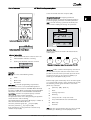
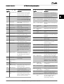
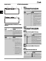
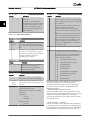
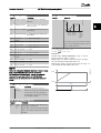
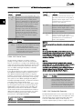
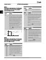
2.1.1 How to Operate Graphical LCP (GLCP)
Status
1(0)
1234rpm
10,4A
a
43,5Hz
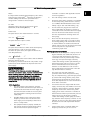
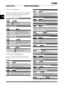
The following instructions are valid for the GLCP (LCP 102).
The GLCP is divided into four functional groups
1.
Graphical display with Status lines.
2.
Menu keys and indicator lights (LEDs) - selecting
mode, changing parameters and switching
between display functions.
3.
Navigation keys and indicator lights (LEDs).
4.
Operation keys and indicator lights (LEDs).
1
Status
2
c.
Alarm
Log
ck
Ba
Info
3
OK
On
Warn.
Status line Status messages displaying icons and
graphics.
Line 1-2Operator data lines displaying data and
variables defined or chosen by the user. By
pressing the [Status] key, up to one extra line can
be added.
Main
Menu
l
ce
b.
Quick
Menu
n
Ca
a.
c
Run OK
Graphical display
The LCD-display is back-lit with a total of 6 alpha-numeric
lines. All data is displayed on the LCP which can show up
to five operating variables while in [Status] mode.
Display lines
b
43,5Hz
Alarm
4
Hand
on
Off
Auto
on
Reset
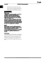
Status line Status messages displaying text.
The display is divided into 3 sections
Top section (a) shows the status when in status mode or
up to 2 variables when not in status mode and in the case
of Alarm/Warning.
The number of the Active Set-up (selected as the Active
Set-up in 0-10 Active Set-up) is shown. When programming
in another Set-up than the Active Set-up, the number of
the Set-up being programmed appears to the right in
brackets.
The Middle section (b) shows up to 5 variables with related
unit, regardless of status. In case of alarm/warning, the
warning is shown instead of the variables.
The Bottom section (c) always shows the state of the
frequency converter in Status mode.
MG11CD02 - VLT® is a registered Danfoss trademark
9
2 2
Status
1 (1)
5.25A
207RPM
24.4 kW
1.1
6.9
Hz
Each value/measurement readout parameter selected in
0-20 Display Line 1.1 Small to 0-24 Display Line 3 Large has
its own scale and number of digits after a possible decimal
point. Larger numeric values are displayed with few digits
after the decimal point.
Ex.: Current readout
5.25 A; 15.2 A 105 A.
2
Status display III
This state displays the event and action of the Smart Logic
Control. For further information, see 3.13 Main Menu Smart Logic - Group 13.
Status
778 RPM
799 RPM
1.1
0.000
1.2
2
7.83 A
4.0 kW
Display Contrast Adjustment
Status
43 RPM
! 1(1)
5.44 A
25.3kW
130BP074.10
Press [status] and [▲] for darker display
Press [status] and [▼] for brighter display
53.2 %
1.4 Hz
Middle section
2.9%
Bottom section
! Pwr.card temp (W29)
Auto Remote Running
Auto Remote Ramping
3
Indicator lights (LEDs)
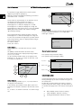
1.3
Status display II
See the operating variables (1.1, 1.2, 1.3, and 2) shown in
the display in this illustration.
In the example, Speed, Motor current, Motor power and
Frequency are selected as variables in the first and second
lines.
1.1, 1.2 and 1.3 are shown in small size. 2 is shown in large
size.
10
1 (1)
0.86 A
State: 0 off 0 (off )
When: Do: -
Top section
1 (1)
36.4 kw
1.2
Auto Remote Running
Auto Remote Running
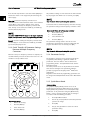
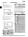
Status display I
This read-out state is standard after start-up or initialisation.
Use [INFO] to obtain information about the value/
measurement linked to the displayed operating variables
(1.1, 1.2, 1.3, 2, and 3).
See the operating variables shown in the display in this
illustration. 1.1, 1.2 and 1.3 are shown in small size. 2 and
3 are shown in medium size.
Status
1.3
130BP063.10
Several values or measurements can be linked to each of
the displayed operating variables. The values /
measurements to be displayed can be defined via
0-20 Display Line 1.1 Small, 0-21 Display Line 1.2 Small,
0-22 Display Line 1.3 Small, 0-23 Display Line 2 Large and
0-24 Display Line 3 Large, which can be accessed via [QUICK
MENU], "Q3 Function Setups", "Q3-1 General Settings",
"Q3-13 Display Settings".
130BP062.10
It is possible to toggle between three status read-out
displays by pressing the [Status] key.
Operating variables with different formatting are shown in
each status screen - see below.
130BP041.10
2 2
VLT® HVAC Drive Programming Guide
How to Programme
If certain threshold values are exceeded, the alarm and/or
warning LED lights up. A status and alarm text appear on
the control panel.
The On LED is activated when the frequency converter
receives power from mains voltage, a DC bus terminal, or
an external 24V supply. At the same time, the back light is
on.
•
•
•
Green LED/On: Control section is working.
Yellow LED/Warn.: Indicates a warning.
Flashing Red LED/Alarm: Indicates an alarm.
MG11CD02 - VLT® is a registered Danfoss trademark
VLT® HVAC Drive Programming Guide
applications and specific functions related to Fans, Pumps
and Compressors.
130BP044.10
How to Programme
On
The Quick Menu parameters can be accessed immediately
unless a password has been created via 0-60 Main Menu
Password, 0-61 Access to Main Menu w/o Password,
0-65 Personal Menu Password or 0-66 Access to Personal
Menu w/o Password.
It is possible to switch directly between Quick Menu mode
and Main Menu mode.
Warn.
Alarm
GLCP keys
Status
Quick
Menu
Main
Menu
Alarm
Log
130BP045.10
Menu keys
The menu keys are divided into functions. The keys below
the display and indicator lamps are used for parameter setup, including choice of display indication during normal
operation.
[Status]
indicates the status of the frequency converter and/or the
motor. 3 different readouts can be chosen by pressing the
[Status] key:
5 line readouts, 4 line readouts or Smart Logic Control.
Use [Status] for selecting the mode of display or for
changing back to Display mode from either the Quick
Menu mode, the Main Menu mode or Alarm mode. Also
use the [Status] key to toggle single or double read-out
mode.
[Quick Menu]
allows quick set-up of the frequency converter. The most
common VLT® HVAC Drive functions can be programmed
here.
Quick Set-up
-
Function Set-up
-
Changes Made
-
Loggings
[Alarm Log]
displays an Alarm list of the ten latest alarms (numbered
A1-A10). To obtain additional details about an alarm, use
the arrow keys to manoeuvre to the alarm number and
press [OK]. Information is displayed about the condition of
the frequency converter before it enters the alarm mode.
The Alarm log button on the LCP allows access to both
Alarm log and Maintenance log.
[Back]
reverts to the previous step or layer in the navigation
structure.
The [Quick Menu] consists of
My Personal Menu
-
[Main Menu]
is used for programming all parameters. The Main Menu
parameters can be accessed immediately unless a
password has been created via 0-60 Main Menu Password,
0-61 Access to Main Menu w/o Password, 0-65 Personal Menu
Password or 0-66 Access to Personal Menu w/o Password. For
the majority of VLT® HVAC Drive applications it is not
necessary to access the Main Menu parameters but instead
the Quick Menu, Quick Set-up and Function Set-up
provides the simplest and quickest access to the typical
required parameters.
It is possible to switch directly between Main Menu mode
and Quick Menu mode.
Parameter shortcut can be carried out by pressing down
the [Main Menu] key for 3 seconds. The parameter shortcut
allows direct access to any parameter.
[Cancel]
last change or command will be cancelled as long as the
display has not been changed.
The Function set-up provides quick and easy access to all
parameters required for the majority of VLT® HVAC Drive
applications including most VAV and CAV supply and
return fans, cooling tower fans, Primary, Secondary and
Condenser Water Pumps and other pump, fan and
compressor applications. Amongst other features it also
includes parameters for selecting which variables to display
on the LCP, digital preset speeds, scaling of analog
references, closed loop single zone and multi-zone
[Info]
displays information about a command, parameter, or
function in any display window. [Info] provides detailed
information when needed.
Exit Info mode by pressing either [Info], [Back], or [Cancel].
Back
MG11CD02 - VLT® is a registered Danfoss trademark
Cancel
Info
11
2 2
Navigation Keys
The four navigation arrows are used to navigate between
the different choices available in [Quick Menu], [Main
Menu] and [Alarm Log]. Use the keys to move the cursor.
l
ce
ck
n
Ca
130BT117.10
[OK] is used for choosing a parameter marked by the
cursor and for enabling the change of a parameter.
Ba
[Off]
stops the connected motor. The key can be selected as
Enabled [1] or Disabled [0] via 0-41 [Off] Key on LCP. If no
external stop function is selected and the [Off] key is
inactive the motor can only be stopped by disconnecting
the mains supply.
[Auto On]
enables the frequency converter to be controlled via the
control terminals and/or serial communication. When a
start signal is applied on the control terminals and/or the
bus, the frequency converter will start. The key can be
selected as Enabled [1] or Disabled [0] via 0-42 [Auto on]
Key on LCP.
NOTE
Info
OK
On
An active HAND-OFF-AUTO signal via the digital inputs has
higher priority than the control keys [Hand On] – [Auto
On].
Warm
[Reset]
is used for resetting the frequency converter after an alarm
(trip). It can be selected as Enable [1] or Disable [0] via
0-43 [Reset] Key on LCP.
Alarm
Operation Keys for local control are found at the bottom
of the control panel.
Hand
on
Off
Auto
on
Reset
130BP046.10
2 2
VLT® HVAC Drive Programming Guide
How to Programme
[Hand On]
enables control of the frequency converter via the GLCP.
[Hand On] also starts the motor, and it is now possible to
enter the motor speed data by means of the arrow keys.
The key can be selected as Enable [1] or Disable [0] via
0-40 [Hand on] Key on LCP.
The following control signals will still be active when
[Hand On] is activated:
•
•
•
•
•
•
•
•
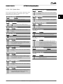
[Hand On] - [Off] - [Auto On]
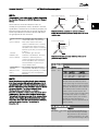
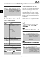
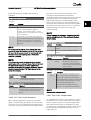
2.1.2 How to Operate Numeric LCP (NLCP)
The following instructions are valid for the NLCP (LCP 101).
The control panel is divided into four functional groups:
1.
Numeric display.
2.
Menu key and indicator lights (LEDs) - changing
parameters and switching between display
functions.
3.
Navigation keys and indicator lights (LEDs).
4.
Operation keys and indicator lights (LEDs).
Reset
NOTE
Coasting stop inverse
Parameter copy is not possible with Numeric Local Control
Panel (LCP101).
Reversing
Set-up select lsb - Set-up select msb
Stop command from serial communication
Quick stop
DC brake
NOTE
External stop signals activated by means of control signals
or a serial bus will override a “start” command via the LCP.
12
The parameter shortcut can be carried out by holding
down the [Main Menu] key for 3 seconds. The parameter
shortcut allows direct access to any parameter.
Select one of the following modes:
Status Mode: Displays the status of the frequency
converter or the motor.
If an alarm occurs, the NLCP automatically switches to
status mode.
A number of alarms can be displayed.
Quick Set-up or Main Menu Mode: Display parameters and
parameter settings.
MG11CD02 - VLT® is a registered Danfoss trademark
VLT® HVAC Drive Programming Guide
130BA191.10
How to Programme
Quick
Setup
Main
Menu
Auto
on
Reset
Ba
ck
Menu
130BP079.10
Status
2
2 2
Navigation Keys [Back] for stepping backwards
Arrow [▼] [▲] keys are used for manoeuvring between
parameter groups, parameters and within parameters.
[OK] is used for choosing a parameter marked by the
cursor and for enabling the change of a parameter.
Setup
1
Select the wanted data value and press [OK]
3
OK
On
P 2-03
Warn.
Alarm
4
Hand
on
Off
Setup 1
Illustration 2.1 Numerical LCP (NLCP)
rpm
Status
Quick
Setup
Main
Menu
130BP077.10
Setup 1
Illustration 2.2 Status Display Example
Operation Keys
Keys for local control are found at the bottom of the
control panel.
Indicator lights (LEDs):
• Green LED/On: Indicates if control section is on.
Yellow LED/Wrn.: Indicates a warning.
Flashing red LED/Alarm: Indicates an alarm.
A 17
130BP078.10
•
•
Setup 1
Hand
on
Off
Auto
on
Reset
130BP046.10
22.8
Menu
Illustration 2.4 Operation keys of the numerical CP (NLCP)
Illustration 2.3 Alarm Display Example
Menu key
[Menu] Select one of the following modes:
•
•
•
Status
Quick Setup
Main Menu
Main Menu is used for programming all parameters.
The parameters can be accessed immediately unless a
password has been created via 0-60 Main Menu Password,
0-61 Access to Main Menu w/o Password, 0-65 Personal Menu
Password or 0-66 Access to Personal Menu w/o Password.
Quick Setup is used to set up the frequency converter
using only the most essential parameters.
The parameter values can be changed using the up/down
arrows when the value is flashing.
Select Main Menu by pressing the [Menu] key a number of
times until the Main Menu LED is lit.
Select the parameter group [xx-__] and press [OK]
Select the parameter [__-xx] and press [OK]
If the parameter is an array parameter select the array
number and press [OK]
[Hand On] enables control of the frequency converter via
the LCP. [Hand on] also starts the motor and it is now
possible to enter the motor speed data by means of the
arrow keys. The key can be selected as Enable [1] or
Disable [0] via 0-40 [Hand on] Key on LCP.
External stop signals activated by means of control signals
or a serial bus will override a 'start' command via the LCP.
The following control signals will still be active when
[Hand on] is activated:
•
•
•
•
•
•
•
•
[Hand on] - [Off] - [Auto on]
Reset
Coasting stop inverse
Reversing
Set-up select lsb - Set-up select msb
Stop command from serial communication
Quick stop
DC brake
[Off] stops the connected motor. The key can be selected
as Enable [1] or Disable [0] via 0-41 [Off] Key on LCP.
MG11CD02 - VLT® is a registered Danfoss trademark
13
If no external stop function is selected and the [Off] key is
inactive the motor can be stopped by disconnecting the
mains supply.
[Auto On] enables the frequency converter to be
controlled via the control terminals and/or serial communication. When a start signal is applied on the control
terminals and/or the bus, the frequency converter will
start. The key can be selected as Enable [1] or Disable [0]
via 0-42 [Auto on] Key on LCP.
NOTE
An active HAND-OFF-AUTO signal via the digital inputs has
higher priority than the control keys [Hand On] [Auto On].
[Reset] is used for resetting the frequency converter after
an alarm (trip). It can be selected as Enable [1] or Disable
[0] via 0-43 [Reset] Key on LCP.
2.1.3 Quick Transfer of Parameter Settings
between Multiple Frequency
Converters
Alarm
Log
Main
Menu
ck
n
Ca
l
ce
Info
OK
On
Warn.
Alarm
Hand
on
Off
Data storage in LCP
1.
Go to 0-50 LCP Copy
14
2.
Press the [OK] key
3.
Select “All to LCP”
4.
Press the [OK] key
Auto
on
Reset
NOTE
Stop the motor before performing this operation.
Connect the LCP to another frequency converter and copy
the parameter settings to this frequency converter as well.
Data transfer from LCP to frequency converter
1.
Go to 0-50 LCP Copy
2.
Press the [OK] key
3.
Select “All from LCP”
4.
Press the [OK] key
The parameter settings stored in the LCP are now
transferred to the frequency converter indicated by the
progress bar. When 100% is reached, press [OK].
Stop the motor before performing this operation.
130BA027.10
Quick
Menu
Status
All parameter settings are now stored in the LCP indicated
by the progress bar. When 100% is reached, press [OK].
NOTE
Once the set-up of a frequency converter is complete, we
recommend that you store the data in the LCP or on a PC
via MCT 10 Set-up Software Tool.
Ba
2 2
VLT® HVAC Drive Programming Guide
How to Programme
2.1.4 Parameter Set-Up
The frequency converter can be used for practically all
assignments, thus offering a significant number of
parameters. The series offers a choice between two
programming modes - the Quick Menu mode and the
Main Menu mode.
The latter provides access to all parameters. The former
takes the user through a few parameters making it
possible to program the majority of VLT® HVAC Drive
applications.
Regardless of the mode of programming, parameters can
be changed in both Quick Menu mode and in Main Menu
mode.
2.1.5 Quick Menu Mode
Parameter Data
The graphical display (GLCP) provides access to all
parameters listed under the Quick Menus. The numeric
display (NLCP) only provides access to the Quick Setup
parameters. To set parameters using the [Quick Menu]
button - enter or change parameter data or settings in
accordance with the following procedure
1.
Press Quick Menu button
2.
Use the [▲] and [▼] buttons to find the parameter
you want to change
3.
Press [OK]
4.
Use [▲] and [▼] buttons to select the correct
parameter setting
5.
Press [OK]
MG11CD02 - VLT® is a registered Danfoss trademark
VLT® HVAC Drive Programming Guide
6.
To move to a different digit within a parameter
setting, use the [◀] and [▶] buttons
7.
Highlighted area indicates digit selected for
change
8.
Press [Cancel] button to disregard change, or
press [OK] to accept change and enter the new
setting
Example of changing parameter data
Assume 22-60 Broken Belt Function is set to [Off]. However,
you want to monitor the fan-belt condition - non- broken
or broken - according to the following procedure
After pressing [Quick Menu], the different choices in the
Quick Menu are listed. See also illustration 6.1 below and
tables Q3-1 to Q3-4 in the following Function Setups
section.
Example of using the Quick Setup option
Assume you want to set the Ramp Down Time to 100
seconds:
1.
Select [Quick Setup]. 0-01 Language in Quick
Setup appears
2.
Press [▼] repeatedly until 3-42 Ramp 1 Ramp
Down Time appears with the default setting of 20
seconds
1.
Press Quick Menu key
3.
Press [OK]
2.
Choose Function Setups with the [▼] button
4.
3.
Press [OK]
Use the [◀] button to highlight the 3rd digit
before the comma
4.
Choose Application Settings with the [▼] button
5.
Change '0' to '1' by using the [▲] button
5.
Press [OK]
6.
Use the [▶] button to highlight the digit '2'
6.
Press [OK] again for Fan Functions
7.
Change '2' to '0' with the [▼] button
7.
Choose Broken Belt Function by pressing [OK]
8.
Press [OK]
8.
With [▼] button, choose [2] Trip
The frequency converter will now trip if a broken fan-belt
is detected.
Select [My Personal Menu] to display personal parameters
For example, an AHU or pump OEM may have preprogrammed personal parameters to be in My Personal
Menu during factory commissioning to make on-site
commissioning/fine tuning simpler. These parameters are
selected in 0-25 My Personal Menu. Up to 20 different
parameters can be programmed in this menu.
Select [Changes Made] to get information about
• The last 10 changes. Use the up/down navigation
keys to scroll between the last 10 changed
parameters.
•
The changes made since default setting.
Select [Loggings]
to get information about the display line read-outs. The
information is shown as graphs.
Only display parameters selected in 0-20 Display Line 1.1
Small and 0-24 Display Line 3 Large can be viewed. It is
possible to store up to 120 samples in the memory for
later reference.
2 2
The new ramp-down time is now set to 100 sec.
It is recommended to do the set-up in the order listed.
NOTE
A complete description of the function is found in
3 Parameter Description.
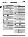
40.0%
Quick Menus
4.84 A
1(1)
Q1 My Personal Menu
130BP064.10
How to Programme
Q2 Quick Setup
Q3 Function Setups
Q5 Changes Made
Illustration 2.5 Quick Menu View
The Quick Setup menu gives access to the 18 most
important setup parameters of the frequency converter.
After programming the frequency converter will, in most
cases, be ready for operation. The 18 Quick Setup
parameters are shown in the table below. A complete
description of the function is given in the parameter
description sections of this manual.
Quick Setup
Efficient Parameter Set-up for VLT® HVAC Drive
Applications
The parameters can easily be set up for the vast majority
of the VLT® HVAC Drive applications only by using the
[Quick Setup] option.
MG11CD02 - VLT® is a registered Danfoss trademark
15
[Units]
How to access Function set-up - example
1-20 Motor Power [kW]
[kW]
Step 1: Turn on the frequency converter (yellow LED lights)
1-21 Motor Power [HP]
[HP]
1-22 Motor Voltage*
[V]
1-23 Motor Frequency
[Hz]
1-24 Motor Current
[A]
1-25 Motor Nominal Speed
[RPM]
1-28 Motor Rotation Check
[Hz]
3-41 Ramp 1 Ramp Up Time
[s]
3-42 Ramp 1 Ramp Down Time
[s]
4-11 Motor Speed Low Limit [RPM]
[RPM]
4-12 Motor Speed Low Limit [Hz]*
[Hz]
4-13 Motor Speed High Limit [RPM]
[RPM]
4-14 Motor Speed High Limit [Hz]*
[Hz]
3-19 Jog Speed [RPM]
[RPM]
13.7%
3-11 Jog Speed [Hz]*
[Hz]
Quick Menus
Parameter
Status
1 (1)
28.8%
14.4Hz
0kWh
Auto Remote Running
Step 2: Press the [Quick Menus] button (Quick Menus
choices appear).
13.0A
1(1)
Q1 My Personal Menu
5-40 Function Relay**
130BT111.10
5-12 Terminal 27 Digital Input
Q2 Quick Setup
Q3 Function Setups
*The display showing depends on choices made in 0-02 Motor Speed
Unit and 0-03 Regional Settings. The default settings of 0-02 Motor
Speed Unit and 0-03 Regional Settings depend on which region of
the world the frequency converter is supplied to but can be reprogrammed as required.
** 5-40 Function Relay, is an array, where one may choose between
Relay1 [0] or Relay2 [1]. Standard setting is Relay1 [0] with the
default choice Alarm [9].
See the parameter description in the section Commonly Used
Parameters.
For a detailed information about settings and
programming, please see the VLT® HVAC Drive
Programming Guide, MG.11.CX.YY
Q5 Changes Made
Step 3: Use the up/down navigation keys to scroll down to
Function set-ups. Press [OK].
69.3%
5.20A
1(1)
Quick Menus
Q1 My Personal Menu
130BT112.10
Table 2.1 Quick Setup parameters
Q2 Quick Setup
Q3 Function Setups
Q5 Changes Made
28.4%
NOTE
2.05A
Function Setups
If [No Operation] is selected in 5-12 Terminal 27 Digital
Input, no connection to +24V on terminal 27 is necessary
to enable start.
If [Coast Inverse] (factory default value) is selected in
5-12 Terminal 27 Digital Input, a connection to +24V is
necessary to enable start.
1(1)
Q3
Q3-1 General Settings
130BT113.10
Step 4: Function set-ups choices appear. Choose Q3-1
General Settings. Press [OK].
x=version number
y=language
Q3-2 Open Loop Settings
Q3-3 Closed Loop Settings
Q3-4 Application Settings
Step 5: Use the up/down navigation keys to scroll down to
i.e. Q3-11 Analog Outputs. Press [OK].
2.1.6 Function Set-ups
The Function set-up provides quick and easy access to all
parameters required for the majority of VLT® HVAC Drive
applications including most VAV and CAV supply and
return fans, cooling tower fans, Primary, Secondary and
Condenser Water Pumps and other pump, fan and
compressor applications.
16
2.63kW
5.66A
130BT110.11
0-01 Language
26.0%
General Settings
7.14A
Q3 - 10 Adv. Motor Settings
Q3 - 11 Analog Output
Q3 - 12 Clock Settings
Q3 - 13 Display Settings
MG11CD02 - VLT® is a registered Danfoss trademark
1(1)
Q3-1
130BT114.10
2 2
VLT® HVAC Drive Programming Guide
How to Programme
Step 6: Choose 6-50 Terminal 42 Output. Press [OK].
5.82A
1(1)
03.11
6 - 50 Terminal 42 Output
130BA115.10
26.3%
Analog Output
43.4%
Analog Output
7.99A
6-50 Terminal 42 Output
[107]
1(1)
Q3-11
130BT116.10
VLT® HVAC Drive Programming Guide
How to Programme
Speed
(100) Output frequency
Step 7: Use the up/down navigation keys to select
between the different choices. Press [OK].
Function Set-ups parameters
The Function Set-ups parameters are grouped in the following way
Q3-1 General Settings
Q3-10 Adv. Motor Settings
Q3-11 Analog Output
Q3-12 Clock Settings
1-90 Motor Thermal Protection
6-50 Terminal 42 Output
0-70 Date and Time
Q3-13 Display Settings
0-20 Display Line 1.1 Small
1-93 Thermistor Source
6-51 Terminal 42 Output Min
Scale
0-71 Date Format
0-21 Display Line 1.2 Small
1-29 Automatic Motor Adaptation 6-52 Terminal 42 Output Max
(AMA)
Scale
0-72 Time Format
0-22 Display Line 1.3 Small
14-01 Switching Frequency
0-74 DST/Summertime
0-23 Display Line 2 Large
4-53 Warning Speed High
0-76 DST/Summertime Start
0-24 Display Line 3 Large
0-77 DST/Summertime End
0-37 Display Text 1
0-38 Display Text 2
0-39 Display Text 3
Q3-2 Open Loop Settings
Q3-20 Digital Reference
Q3-21 Analog Reference
3-02 Minimum Reference
3-02 Minimum Reference
3-03 Maximum Reference
3-03 Maximum Reference
3-10 Preset Reference
6-10 Terminal 53 Low Voltage
5-13 Terminal 29 Digital Input
6-11 Terminal 53 High Voltage
5-14 Terminal 32 Digital Input
6-12 Terminal 53 Low Current
5-15 Terminal 33 Digital Input
6-13 Terminal 53 High Current
6-14 Terminal 53 Low Ref./Feedb. Value
6-15 Terminal 53 High Ref./Feedb. Value
MG11CD02 - VLT® is a registered Danfoss trademark
17
2 2
2 2
How to Programme
VLT® HVAC Drive Programming Guide
Q3-3 Closed Loop Settings
Q3-30 Single Zone Int. Set Point
Q3-31 Single Zone Ext. Set Point
Q3-32 Multi Zone / Adv
1-00 Configuration Mode
1-00 Configuration Mode
1-00 Configuration Mode
20-12 Reference/Feedback Unit
20-12 Reference/Feedback Unit
3-15 Reference 1 Source
20-13 Minimum Reference/Feedb.
20-13 Minimum Reference/Feedb.
3-16 Reference 2 Source
20-14 Maximum Reference/Feedb.
20-14 Maximum Reference/Feedb.
20-00 Feedback 1 Source
6-22 Terminal 54 Low Current
6-10 Terminal 53 Low Voltage
20-01 Feedback 1 Conversion
6-24 Terminal 54 Low Ref./Feedb. Value
6-11 Terminal 53 High Voltage
20-02 Feedback 1 Source Unit
6-25 Terminal 54 High Ref./Feedb. Value
6-12 Terminal 53 Low Current
20-03 Feedback 2 Source
6-26 Terminal 54 Filter Time Constant
6-13 Terminal 53 High Current
20-04 Feedback 2 Conversion
6-27 Terminal 54 Live Zero
6-14 Terminal 53 Low Ref./Feedb. Value
20-05 Feedback 2 Source Unit
6-00 Live Zero Timeout Time
6-15 Terminal 53 High Ref./Feedb. Value
20-06 Feedback 3 Source
6-01 Live Zero Timeout Function
6-22 Terminal 54 Low Current
20-07 Feedback 3 Conversion
20-21 Setpoint 1
6-24 Terminal 54 Low Ref./Feedb. Value
20-08 Feedback 3 Source Unit
20-81 PID Normal/ Inverse Control
6-25 Terminal 54 High Ref./Feedb. Value
20-12 Reference/Feedback Unit
20-82 PID Start Speed [RPM]
6-26 Terminal 54 Filter Time Constant
20-13 Minimum Reference/Feedb.
20-83 PID Start Speed [Hz]
6-27 Terminal 54 Live Zero
20-14 Maximum Reference/Feedb.
20-93 PID Proportional Gain
6-00 Live Zero Timeout Time
6-10 Terminal 53 Low Voltage
20-94 PID Integral Time
6-01 Live Zero Timeout Function
6-11 Terminal 53 High Voltage
20-70 Closed Loop Type
20-81 PID Normal/ Inverse Control
6-12 Terminal 53 Low Current
20-71 PID Performance
20-82 PID Start Speed [RPM]
6-13 Terminal 53 High Current
20-72 PID Output Change
20-83 PID Start Speed [Hz]
6-14 Terminal 53 Low Ref./Feedb. Value
20-73 Minimum Feedback Level
20-93 PID Proportional Gain
6-15 Terminal 53 High Ref./Feedb. Value
20-74 Maximum Feedback Level
20-94 PID Integral Time
6-16 Terminal 53 Filter Time Constant
20-79 PID Autotuning
20-70 Closed Loop Type
6-17 Terminal 53 Live Zero
20-71 PID Performance
6-20 Terminal 54 Low Voltage
20-72 PID Output Change
6-21 Terminal 54 High Voltage
20-73 Minimum Feedback Level
6-22 Terminal 54 Low Current
20-74 Maximum Feedback Level
6-23 Terminal 54 High Current
20-79 PID Autotuning
6-24 Terminal 54 Low Ref./Feedb. Value
6-25 Terminal 54 High Ref./Feedb. Value
6-26 Terminal 54 Filter Time Constant
6-27 Terminal 54 Live Zero
6-00 Live Zero Timeout Time
6-01 Live Zero Timeout Function
4-56 Warning Feedback Low
4-57 Warning Feedback High
20-20 Feedback Function
20-21 Setpoint 1
20-22 Setpoint 2
20-81 PID Normal/ Inverse Control
20-82 PID Start Speed [RPM]
20-83 PID Start Speed [Hz]
20-93 PID Proportional Gain
20-94 PID Integral Time
20-70 Closed Loop Type
20-71 PID Performance
20-72 PID Output Change
20-73 Minimum Feedback Level
20-74 Maximum Feedback Level
20-79 PID Autotuning
18
MG11CD02 - VLT® is a registered Danfoss trademark
VLT® HVAC Drive Programming Guide
How to Programme
Q3-4 Application Settings
Q3-40 Fan Functions
Q3-41 Pump Functions
Q3-42 Compressor Functions
22-60 Broken Belt Function
22-20 Low Power Auto Set-up
1-03 Torque Characteristics
22-61 Broken Belt Torque
22-21 Low Power Detection
1-71 Start Delay
22-62 Broken Belt Delay
22-22 Low Speed Detection
22-75 Short Cycle Protection
4-64 Semi-Auto Bypass Set-up
22-23 No-Flow Function
22-76 Interval between Starts
1-03 Torque Characteristics
22-24 No-Flow Delay
22-77 Minimum Run Time
22-22 Low Speed Detection
22-40 Minimum Run Time
5-01 Terminal 27 Mode
22-23 No-Flow Function
22-41 Minimum Sleep Time
5-02 Terminal 29 Mode
22-24 No-Flow Delay
22-42 Wake-up Speed [RPM]
5-12 Terminal 27 Digital Input
22-40 Minimum Run Time
22-43 Wake-up Speed [Hz]
5-13 Terminal 29 Digital Input
22-41 Minimum Sleep Time
22-44 Wake-up Ref./FB Difference
5-40 Function Relay
22-42 Wake-up Speed [RPM]
22-45 Setpoint Boost
1-73 Flying Start
22-43 Wake-up Speed [Hz]
22-46 Maximum Boost Time
1-86 Trip Speed Low [RPM]
22-44 Wake-up Ref./FB Difference
22-26 Dry Pump Function
1-87 Trip Speed Low [Hz]
22-45 Setpoint Boost
22-27 Dry Pump Delay
22-46 Maximum Boost Time
22-80 Flow Compensation
2-10 Brake Function
22-81 Square-linear Curve Approximation
2-16 AC brake Max. Current
22-82 Work Point Calculation
2-17 Over-voltage Control
22-83 Speed at No-Flow [RPM]
1-73 Flying Start
22-84 Speed at No-Flow [Hz]
1-71 Start Delay
22-85 Speed at Design Point [RPM]
1-80 Function at Stop
22-86 Speed at Design Point [Hz]
2-00 DC Hold/Preheat Current
22-87 Pressure at No-Flow Speed
4-10 Motor Speed Direction
22-88 Pressure at Rated Speed
2 2
22-89 Flow at Design Point
22-90 Flow at Rated Speed
1-03 Torque Characteristics
1-73 Flying Start
2.1.7 Main Menu Mode
1107 RPM
3.84 A
Main menu
0 - ** Operation/Display
1 (1)
130BP066.10
Select the Main Menu mode by pressing the [Main Menu]
key. The below read-out appears on the display.
The middle and bottom sections on the display show a list
of parameter groups which can be chosen by toggling the
up and down buttons.
1 - ** Load/Motor
All parameters can be changed in the Main Menu.
However, depending on the choice of configuration
(1-00 Configuration Mode), some parameters can be hidden.
2.1.8 Parameter Selection
In the Main Menu mode, the parameters are divided into
groups. You select a parameter group by means of the
navigation keys.
The following parameter groups are accessible
2 - ** Brakes
3 - ** Reference / Ramps
Each parameter has a name and number which remain the
same regardless of the programming mode. In the Main
Menu mode, the parameters are divided into groups. The
first digit of the parameter number (from the left) indicates
the parameter group number.
MG11CD02 - VLT® is a registered Danfoss trademark
19
Parameter group:
0
Operation/Display
740RPM
Basic Settings
1
Load/Motor
0 -01 Language
2
Brakes
3
References/Ramps
4
Limits/Warnings
5
Digital In/Out
6
Analog In/Out
8
Comm. and Options
9
Profibus
10
CAN Fieldbus
11
LonWorks
12
Ethernet IP / Modbus TCP / PROFINET
13
Smart Logic
14
Special Functions
15
Drive Information
16
Data Readouts
18
Data Readouts 2
20
Drive Closed Loop
21
Ext. Closed Loop
22
Application Functions
23
Time-based Functions
25
Cascade Controller
26
Analog I/O Option MCB 109
2.1.11 Changing a Group of Numeric Data
Values
113 RPM
1(1)
1- 6*
1 - 60 Low speed load
compensation
100%
10.64A
1 [1]
0-0*
Use the [▲] [▼] navigation keys to change the data value.
The up key enlarges the data value, and the down key
reduces the data value. Place the cursor on the value you
want to save and press [OK].
729RPM
6.21A
Load depen. setting
1(1)
1- 6*
1 - 60 Low speed load
compensation
16 0%
[0] English
2.1.12 Value, Step-by-Step
2.1.9 Changing Data
The procedure for changing data is the same whether you
select a parameter in the Quick menu or the Main menu
mode. Press [OK] to change the selected parameter.
The procedure for changing data depends on whether the
selected parameter represents a numerical data value or a
text value.
2.1.10 Changing a Text Value
If the selected parameter is a text value, change the text
value with the [▲] [▼] navigation keys.
The up key increases the value, and the down key
decreases the value. Place the cursor on the value you
want to save and press [OK].
20
1.78 A
Load depen. setting
130BP069.10
If the chosen parameter represents a numeric data value,
change the chosen data value by means of the [◀] [▶]
navigation keys as well as the [▲] [▼] navigation keys. Use
the [◀] [▶] navigation keys to move the cursor horizontally.
Certain parameters can be changed step by step or
infinitely varying. This applies to 1-20 Motor Power [kW],
1-22 Motor Voltage and 1-23 Motor Frequency.
The parameters are changed both as a group of numeric
data values and as numeric data values infinitely varying.
2.1.13 Read-out and Programming of
Indexed Parameters
Parameters are indexed when placed in a rolling stack.
15-30 Alarm Log: Error Code to 15-33 Alarm Log: Date and
Time contain a fault log which can be read out. Choose a
parameter, press [OK], and use the up/down navigation
keys to scroll through the value log.
MG11CD02 - VLT® is a registered Danfoss trademark
130BP070.10
0 -01 Language
1 [1]
0-0*
[0] English
After selecting a parameter group, choose a parameter by
means of the navigation keys.
The middle section on the display shows the parameter
number and name as well as the selected parameter value.
740RPM
Basic Settings
10.64 A
130BP068.10
Group no.
130BP067.10
2 2
VLT® HVAC Drive Programming Guide
How to Programme
VLT® HVAC Drive Programming Guide
How to Programme
Use 3-10 Preset Reference as another example:
Choose the parameter, press [OK], and use the up/down
navigation keys keys to scroll through the indexed values.
To change the parameter value, select the indexed value
and press [OK]. Change the value by using the up/down
keys. Press [OK] to accept the new setting. Press [Cancel]
to abort. Press [Back] to leave the parameter.
2.1.14 Initialisation to Default Settings
Initialise the frequency converter to default settings in two
ways.
Manual initialisation
1.
Disconnect from mains and wait until the display turns
off.
2a.
Press [Status] - [Main Menu] - [OK] at the same time
while power up for LCP 102, Graphical Display
2b.
Press [Menu] while power up for LCP 101, Numerical
Display
3.
Release the keys after 5 seconds
4.
The frequency converter is now programmed according
to default settings.
2 2
This procedure initialises all except: 15-00 Operating Hours;
15-03 Power Up's; 15-04 Over Temp's; 15-05 Over Volt's.
Recommended initialisation (via 14-22 Operation Mode)
NOTE
1.
Select 14-22 Operation Mode
2.
Press [OK]
3.
Select “initialisation”
4.
Press [OK]
5.
Cut off the mains supply and wait until the
display turns off.
6.
Reconnect the mains supply - the frequency
converter is now reset.
7.
Change 14-22 Operation Mode back to Normal
Operation.
When you carry out manual initialisation, you also reset
serial communication, 14-50 RFI Filter and fault log settings.
Removes parameters selected in 25-00 Cascade Controller.
NOTE
After initialisation and power cycling, the display will not
show any information until after a couple of minutes.
NOTE
Resets parameters selected in Personal Menu with default
factory setting.
14-22 Operation Mode initialises all except
14-50 RFI Filter
8-30 Protocol
8-31 Address
8-32 Baud Rate
8-35 Minimum Response Delay
8-36 Maximum Response Delay
8-37 Maximum Inter-Char Delay
15-00 Operating Hours to 15-05 Over Volt's
15-20 Historic Log: Event to 15-22 Historic Log: Time
15-30 Alarm Log: Error Code to 15-32 Alarm Log:
Time
MG11CD02 - VLT® is a registered Danfoss trademark
21
3 3
VLT® HVAC Drive Programming Guide
Parameter Description
3 Parameter Description
3.1 Parameter Selection
3.1.1 Main Menu Structure
Parameters for the frequency converter are grouped into
various parameter groups for easy selection of the correct
parameters for optimized operation of the frequency
converter.
The vast majority of VLT® HVAC Drive applications can be
programmed using the Quick Menu button and selecting
the parameters under Quick Setup and Function Setups.
Descriptions and default settings of parameters may be
found under 5 Parameter Lists.
0-** Operation/Display
1-** Load/Motor
2-** Brakes
3-** Reference/Ramps
4-** Limits/ Warnings
5-** Digital In/Out
6-** Analog In/Out
8-** Comm. and Options
9-** Profibus
10-** CAN Fieldbus
11-** LonWorks
12-** Ethernet IP / Modbus TCP / PROFINET
13-** Smart Logic Controller
14-** Special Functions
15-** FC Information
16-** Data Readouts
18-** Info & Readouts
20-** FC Closed Loop
21-** Ext. Closed Loop
22-** Application Functions
23-** Time Based Functions
24-** Application Functions 2
25-** Cascade Controller
26-** Analog I/O Option MCB 109
22
MG11CD02 - VLT® is a registered Danfoss trademark
VLT® HVAC Drive Programming Guide
Parameter Description
3.2 Main Menu - Operation and Display - Group 0
Parameters related to the fundamental functions of the
frequency converter, function of the LCP buttons and
configuration of the LCP display.
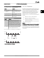
0-02 Motor Speed Unit
Option:
0-02 Motor Speed Unit and 0-03 Regional Settings. The
3.2.1 0-0* Basic Settings
default setting of 0-02 Motor Speed Unit and
0-03 Regional Settings depends on which region of
the world the frequency converter is supplied to, but
can be re-programmed as required.
0-01 Language
Option:
Function:
The display showing depends on settings in
Function:
NOTE
Defines the language to be used in the
display.
The frequency converter can be
delivered with 2 different language
packages. English and German are
included in both packages. English
cannot be erased or manipulated.
[0] * English
Part of Language packages 1 - 2
[1]
Deutsch
Part of Language packages 1 - 2
[2]
Francais
Part of Language package 1
[3]
Dansk
Part of Language package 1
[4]
Spanish
Part of Language package 1
[5]
Italiano
Part of Language package 1
[6]
Svenska
Part of Language package 1
[7]
Nederlands
Part of Language package 1
Changing the Motor Speed Unit will reset certain
parameters to their initial value. It is
recommended to select the motor speed unit
first, before modifying other parameters.
[0]
RPM Selects display of motor speed variables and
parameters (i.e. references, feedbacks and limits) in
terms of motor speed (RPM).
[1] * Hz
Selects display of motor speed variables and
parameters (i.e. references, feedbacks and limits) in
terms of output frequency to the motor (Hz).
NOTE
This parameter cannot be adjusted while the motor is
running.
0-03 Regional Settings
[10] Chinese
Language package 2
[20] Suomi
Part of Language package 1
[22] English US
Part of Language package 1
[27] Greek
Part of Language package 1
[28] Bras.port
Part of Language package 1
Settings. The default setting of 0-02 Motor Speed
[36] Slovenian
Part of Language package 1
[39] Korean
Part of Language package 2
[40] Japanese
Part of Language package 2
Unit and 0-03 Regional Settings depends on
which region of the world the frequency
converter is supplied to but can be reprogrammed as required.
[41] Turkish
Part of Language package 1
[42] Trad.Chinese
Part of Language package 2
[43] Bulgarian
Part of Language package 1
[44] Srpski
Part of Language package 1
[45] Romanian
Part of Language package 1
[46] Magyar
Part of Language package 1
[47] Czech
Part of Language package 1
[48] Polski
Part of Language package 1
[49] Russian
Part of Language package 1
[50] Thai
Part of Language package 2
Option:
Function:
This parameter cannot be adjusted while the
motor is running.
The display showing depends on settings in
0-02 Motor Speed Unit and 0-03 Regional
[0]
International
[1] * North
America
Sets 1-20 Motor Power [kW] units to [kW] and
the default value of 1-23 Motor Frequency [50
Hz].
Sets 1-21 Motor Power [HP] units to HP and the
default value of 1-23 Motor Frequency to 60 Hz.
The setting not used is made invisible.
[51] Bahasa Indonesia Part of Language package 2
[52] Hrvatski
MG11CD02 - VLT® is a registered Danfoss trademark
23
3 3
3 3
Parameter Description
VLT® HVAC Drive Programming Guide
0-04 Operating State at Power-up
Option:
Function:
Select the operating mode upon reconnection
of the frequency converter to mains voltage
after power down when operating in Hand
(local)mode.
[0] * Resume
[1]
Forced
stop,
ref=old
Resumes operation of the frequency converter
maintaining the same local reference and the
same start/stop condition (applied by [Hand
On]/[Off] on the LCP or Hand Start via a digital
input as before the frequency converter was
powered down.
0-10 Active Set-up
Option:
Use 0-51 Set-up Copy to copy a set-up to one
or all other set-ups. To avoid conflicting
settings of the same parameter within two
different set-ups, link the set-ups together
using 0-12 This Set-up Linked to. Stop the
frequency converter before switching between
set-ups where parameters marked ‘not
changeable during operation’ have different
values.
Parameters which are ‘not changeable during
operation’ are marked FALSE in the parameter
lists in the section Parameter Lists
[0]
Define and control the individual parameter set-ups.
The frequency converter has four parameter setups that
can be programmed independently of each other. This
makes the frequency converter very flexible and able to
meet the requirements of many different VLT® HVAC Drive
system control schemes often saving the cost of external
control equipment. For example these can be used to
program the frequency converter to operate according to
one control scheme in one setup (e.g. daytime operation)
and another control scheme in another setup (e.g. night
set back). Alternatively they can be used by an AHU or
packaged unit OEM to identically program all their factory
fitted frequency converters for different equipment models
within a range to have the same parameters and then
during production/commissioning simply select a specific
setup depending on which model within that range the
frequency converter is installed on.
The active setup (i.e. the setup in which the frequency
converter is currently operating) can be selected in
0-10 Active Set-up and is displayed in the LCP. Using Multi
set-up it is possible to switch between set-ups with the
frequency converter running or stopped, via digital input
or serial communication commands (e.g. for night set
back). If it is necessary to change setups whilst running,
ensure 0-12 This Set-up Linked to is programmed as
required. For the majority of VLT® HVAC Drive applications
it will not be necessary to program 0-12 This Set-up Linked
to even if change of set up whilst running is required, but
for very complex applications, using the full flexibility of
the multiple setups, it may be required. Using
0-11 Programming Set-up it is possible to edit parameters
Function:
Select the set-up in which the frequency
converter is to operate.
Uses saved reference [1] to stop the frequency
converter but at the same time retain in
memory the local speed reference prior to
power down. After mains voltage is
reconnected and after receiving a start
command (using the LCP [Hand On] button or
Hand Start command via a digital input) the
frequency converter restarts and operates at
the retained speed reference.
3.2.2 0-1* Set-up Operations
24
within any of the setups whilst continuing the frequency
converter operation in its Active Setup which can be a
different setup to that being edited. Using 0-51 Set-up Copy
it is possible to copy parameter settings between the setups to enable quicker commissioning if similar parameter
settings are required in different set-ups.
Factory
setup
[1] * Set-up 1
[2]
Set-up 2
[3]
Set-up 3
[4]
Set-up 4
[9]
Multi Setup
Cannot be changed. It contains the Danfoss
data set, and can be used as a data source
when returning the other set-ups to a known
state.
Set-up 1 [1] to Set-up 4 [4] are the four
separate parameter set-ups within which all
parameters can be programmed.
Is used for remote selection of set-ups using
digital inputs and the serial communication
port. This set-up uses the settings from
0-12 This Set-up Linked to.
MG11CD02 - VLT® is a registered Danfoss trademark
VLT® HVAC Drive Programming Guide
0-11 Programming Set-up
0-12 This Set-up Linked to
Option:
Option:
Function:
1. Change the edit set-up to Set-up 2 [2] in
Select the set-up to be edited (i.e.
programmed) during operation; either the
active set-up or one of the inactive set-ups.
The set-up number being edited is displayed
in the LCP in (brackets).
Factory
setup
cannot be edited but it is useful as a data
source to return the other set-ups to a
known state.
[1]
Set-up 1
Set-up 1 [1] to Set-up 4 [4] can be edited
freely during operation, independently of the
active set-up.
[2]
Set-up 2
[3]
Set-up 3
[4]
Set-up 4
[9] * Active Setup
0-11 Programming Set-up and set 0-12 This Setup Linked to to Set-up 1 [1]. This will start the
linking (synchronising) process.
0 RPM
0.00A
Set-up Handling
0-12 This Set-up Linked to
1(1)
0-1*
3 3
[1] Setup 1
OR
2. While still in Set-up 1, using 0-50 LCP Copy,
copy Set-up 1 to Set-up 2. Then set 0-12 This
Set-up Linked to to Set-up 2 [2]. This will start
the linking process.
(i.e. the set-up in which the frequency
converter is operating) can also be edited
during operation. Editing parameters in the
chosen setup would normally be done from
the LCP but it is also possible from any of the
serial communication ports.
0 RPM
0.00A
Set-up Handling
0-12 This Set-up Linked to
[2] Setup 2
1(1)
0-1*
130BP076.10
[0]
Function:
130BP075.10
Parameter Description
0-12 This Set-up Linked to
Option:
Function:
After the link is complete, 0-13 Readout: Linked
This parameter only needs to be programmed if
changing set-ups is required whilst the motor is
running. It ensures that parameters which are
"not changeable during operation" have the
same setting in all relevant set-ups.
To enable conflict-free changes from one set-up
to another whilst the frequency converter is
running, link set-ups containing parameters
which are not changeable during operation.
The link will ensure synchronising of the ‘not
changeable during operation’ parameter values
when moving from one set-up to another
during operation. ‘Not changeable during
operation’ parameters can be identified by the
label FALSE in the parameter lists in the section
Parameter Lists.
Set-ups will read {1,2} to indicate that all ‘not
changeable during operation’ parameters are
now the same in Set-up 1 and Set-up 2. If there
are changes to a ‘not changeable during
operation’ parameter, e.g. 1-30 Stator Resistance
(Rs), in Set-up 2, they will also be changed
automatically in Set-up 1. A switch between
Set-up 1 and Set-up 2 during operation is now
possible.
[0] * Not linked
[1]
Set-up 1
[2]
Set-up 2
[3]
Set-up 3
[4]
Set-up 4
The 0-12 This Set-up Linked to feature is used
when Multi set-up in 0-10 Active Set-up is
selected. Multi set-up can be used to move
from one set-up to another during operation
(i.e. while the motor is running).
Example:
Use Multi set-up to shift from Set-up 1 to Setup 2 whilst the motor is running. Programme
parameters in Set-up 1 first, then ensure that
Set-up 1 and Set-up 2 are synchronised (or
‘linked’). Synchronisation can be performed in
two ways:
MG11CD02 - VLT® is a registered Danfoss trademark
25
VLT® HVAC Drive Programming Guide
Parameter Description
0-13 Readout: Linked Set-ups
0-20 Display Line 1.1 Small
Array [5]
Option:
Range:
0*
Function:
[37]
Display Text 1
Enables an individual text string to
be written, for display in the LCP or
to be read via serial communication.
[38]
Display Text 2
Enables an individual text string to
be written, for display in the LCP or
to be read via serial communication.
[39]
Display Text 3
Enables an individual text string to
be written, for display in the LCP or
to be read via serial communication.
[89]
Date and Time
Readout
Displays the current date and time.
[953]
Profibus Warning
Word
Displays Profibus communication
warnings.
[1005]
Readout Transmit
Error Counter
View the number of CAN control
transmission errors since the last
power-up.
[1006]
Readout Receive
Error Counter
View the number of CAN control
receipt errors since the last powerup.
[1007]
Readout Bus Off
Counter
View the number of Bus Off events
since the last power-up.
[1013]
Warning
Parameter
View a DeviceNet-specific warning
word. One separate bit is assigned
to every warning.
[1115]
LON Warning
Word
Shows the LON-specific warnings.
[1117]
XIF Revision
Shows the version of the external
interface file of the Neuron C chip
on the LON option.
[1118]
LonWorks
Revision
Shows the software version of the
application program of the Neuron
C chip on the LON option.
[1230]
Warning
Parameter
[1501]
Running Hours
View the number of running hours
of the motor.
[1502]
kWh Counter
View the mains power consumption
in kWh.
[1600]
Control Word
View the Control Word sent from
the frequency converter via the
serial communication port in hex
code.
[1601]
Reference [Unit]
Total reference (sum of digital/
analog/preset/bus/freeze ref./catch
up and slow-down) in selected unit.
[0 - 255 ] View a list of all the set-ups linked by means of
0-12 This Set-up Linked to. The parameter has one
index for each parameter set-up. The parameter
value displayed for each index represents which
setups are linked to that parameter setup.
3 3
Index
LCP value
0
{0}
1
{1,2}
2
{1,2}
3
{3}
4
{4}
Table 3.2 Example: Set-up 1 and Set-up 2 are
linked
0-14 Readout: Prog. Set-ups / Channel
Range:
0*
Function:
Function:
[-2147483648
- 2147483647 ]
View the setting of 0-11 Programming Setup for each of the four different
communication channels. When the
number is displayed in hex, as it is in the
LCP, each number represents one channel.
Numbers 1-4 represent a set-up number; ‘F’
means factory setting; and ‘A’ means active
set-up. The channels are, from right to left:
LCP, FC-bus, USB, HPFB1.5.
Example: The number AAAAAA21h means
that the FC-bus selected Set-up 2 in
0-11 Programming Set-up, the LCP selected
Set-up 1 and all others used the active setup.
3.2.3 0-2* LCP Display
Define the variables displayed in the Graphical Local
Control Panel.
NOTE
Please refer to 0-37 Display Text 1, 0-38 Display Text 2 and
0-39 Display Text 3 for information on how to write display
texts.
0-20 Display Line 1.1 Small
Option:
Function:
Select a variable for display in line
1, left position.
[0] *
26
None
No display value selected
[1602] * Reference [%]
Total reference (sum of digital/
analog/preset/bus/freeze ref./catch
up and slow-down) in percent.
[1603]
Present status word
Status Word
MG11CD02 - VLT® is a registered Danfoss trademark
VLT® HVAC Drive Programming Guide
Parameter Description
0-20 Display Line 1.1 Small
0-20 Display Line 1.1 Small
Option:
Option:
[1605]
[1609]
Function:
Main Actual Value
[%]
Custom Readout
View the two-byte word sent with
the Status word to the bus Master
reporting the Main Actual Value.
[1634]
Function:
Heatsink Temp.
out limit is 95 ± 5° C; cutting back
in occurs at 70 ± 5° C.
View the user-defined readouts as
defined in 0-30 Custom Readout
Unit, 0-31 Custom Readout Min Value
and 0-32 Custom Readout Max Value.
Present heat sink temperature of
the frequency converter. The cut-
[1635]
Inverter Thermal
Percentage load of the inverters
[1636]
Inv. Nom. Current
Nominal current of the frequency
converter
[1610]
Power [kW]
Actual power consumed by the
motor in kW.
[1637]
Inv. Max. Current
Maximum current of the frequency
converter
[1611]
Power [hp]
Actual power consumed by the
motor in HP.
[1638]
SL Controller
State
State of the event executed by the
control
[1612]
Motor Voltage
Voltage supplied to the motor.
[1639]
Frequency
Motor frequency, i.e. the output
frequency from the frequency
converter in Hz.
Control Card
Temp.
Temperature of the control card.
[1613]
[1643]
Timed Actions
Status
See parameter group 23-0* Timed
[1614]
Motor Current
Phase current of the motor
measured as effective value.
[1615]
Frequency [%]
Motor frequency, i.e. the output
frequency from the frequency
converter in percent.
[1616]
Torque [Nm]
Present motor load as a percentage
of the rated motor torque.
[1617]
Speed [RPM]
Motor speed reference. Actual
speed will depend on slip compensation being used (compensation
set in 1-62 Slip Compensation). If not
used, actual speed will be the value
read in the display minus motor
slip.
[1618]
Motor Thermal
[1622]
Torque [%]
[1626]
Power Filtered
[kW]
[1627]
Power Filtered
[hp]
[1630]
DC Link Voltage
[1632]
[1633]
Thermal load on the motor,
calculated by the ETR function. See
also parameter group 1-9* Motor
Temperature.
Actions.
[1650]
External Reference Sum of the external reference as a
percentage, i.e. the sum of analog/
pulse/bus.
[1652]
Feedback [Unit]
[1653]
Digi Pot Reference View the contribution of the digital
potentiometer to the actual
reference Feedback.
[1654]
Feedback 1 [Unit]
View the value of Feedback 1. See
also par. 20-0*.
[1655]
Feedback 2 [Unit]
View the value of Feedback 2. See
also par. 20-0*.
[1656]
Feedback 3 [Unit]
View the value of Feedback 3. See
Reference value from programmed
digital input(s).
also par. 20-0*.
[1658]
PID Output [%]
Returns the Drive Closed Loop PID
controller output value in percent.
[1660]
Digital Input
Displays the status of the digital
inputs. Signal low = 0; Signal high =
1.
Shows the actual torque produced,
in percentage.
Regarding order, see 16-60 Digital
Input. Bit 0 is at the extreme right.
[1661]
Terminal 53
Switch Setting
Setting of input terminal 53. Current
= 0; Voltage = 1.
Intermediate circuit voltage in the
frequency converter.
[1662]
Analog Input 53
Actual value at input 53 either as a
reference or protection value.
Brake Energy /s
Present brake power transferred to
an external brake resistor.
Stated as an instantaneous value.
[1663]
Terminal 54
Switch Setting
Setting of input terminal 54. Current
= 0; Voltage = 1.
[1664]
Analog Input 54
Brake Energy /2
min
Brake power transferred to an
external brake resistor. The mean
power is calculated continuously for
the most recent 120 seconds.
Actual value at input 54 either as
reference or protection value.
[1665]
Analog Output 42
[mA]
Actual value at output 42 in mA.
MG11CD02 - VLT® is a registered Danfoss trademark
Use 6-50 Terminal 42 Output to
select the variable to be
represented by output 42.
27
3 3
3 3
VLT® HVAC Drive Programming Guide
Parameter Description
0-20 Display Line 1.1 Small
0-20 Display Line 1.1 Small
Option:
Option:
Function:
Function:
[1666]
Digital Output
[bin]
Binary value of all digital outputs.
[1693]
Warning Word 2
[1667]
Pulse Input #29
[Hz]
Actual value of the frequency
applied at terminal 29 as a pulse
input.
One or more warnings in a Hex
code (used for serial communications)
[1694]
Ext. Status Word
Pulse Input #33
[Hz]
Actual value of the frequency
applied at terminal 33 as a pulse
input.
One or more status conditions in a
Hex code (used for serial communications)
[1695]
[1669]
Pulse Output #27
[Hz]
Actual value of pulses applied to
terminal 27 in digital output mode.
Ext. Status Word 2 One or more status conditions in a
Hex code (used for serial communications)
[1696]
[1670]
Pulse Output #29
[Hz]
Actual value of pulses applied to
terminal 29 in digital output mode.
Maintenance
Word
[1671]
Relay Output [bin] View the setting of all relays.
The bits reflect the status for the
programmed Preventive
Maintenance Events in parameter
group 23-1*
[1672]
Counter A
View the present value of Counter
A.
[1830]
Analog Input
X42/1
Shows the value of the signal
applied to terminal X42/1 on the
Analog I/O card.
[1673]
Counter B
View the present value of Counter
B.
[1831]
Analog Input
X42/3
[1675]
Analog In X30/11
Actual value of the signal on input
X30/11 (General Purpose I/O Card.
Option)
Shows the value of the signal
applied to terminal X42/3 on the
Analog I/O card.
[1832]
Analog Input
X42/5
Shows the value of the signal
applied to terminal X42/5 on the
Analog I/O card.
[1833]
Analog Out X42/7
[V]
Shows the value of the signal
applied to terminal X42/7 on the
Analog I/O card.
[1834]
Analog Out X42/9
[V]
Shows the value of the signal
applied to terminal X42/9 on the
Analog I/O card.
[1835]
Analog Out
X42/11 [V]
Shows the value of the signal
applied to terminal X42/11 on the
Analog I/O card.
[1836]
Analog Input
X48/2 [mA]
[1837]
Temp. Input
X48/4
[1668]
[1676]
[1677]
Analog In X30/12
Analog Out X30/8
[mA]
Actual value of the signal on input
X30/12 (General Purpose I/O Card.
Optional)
Actual value at output X30/8
(General Purpose I/O Card. Optional)
Use 6-60 Terminal X30/8 Output to
select the variable to be shown.
[1680]
Fieldbus CTW 1
Control word (CTW) received from
the Bus Master.
[1682]
Fieldbus REF 1
Main reference value sent with
control word via the serial
communications network e.g. from
the BMS, PLC or other master
controller.
[1684]
Comm. Option
STW
Extended fieldbus communication
option status word.
[1838]
Temp. Input
X48/7
[1685]
FC Port CTW 1
Control word (CTW) received from
the Bus Master.
[1839]
Temp. Input
X48/10
[1686]
FC Port REF 1
Status word (STW) sent to the Bus
Master.
[1850]
Sensorless
Readout [unit]
[1690]
Alarm Word
One or more alarms in a Hex code
(used for serial communications)
[2117]
Ext. 1 Reference
[Unit]
The value of the reference for
extended Closed Loop Controller 1
[1691]
Alarm Word 2
One or more alarms in a Hex code
(used for serial communications)
[2118]
Ext. 1 Feedback
[Unit]
The value of the feedback signal for
extended Closed Loop Controller 1
[1692]
Warning Word
One or more warnings in a Hex
code (used for serial communications)
[2119]
Ext. 1 Output [%]
The value of the output from
extended Closed Loop Controller 1
[2137]
Ext. 2 Reference
[Unit]
The value of the reference for
extended Closed Loop Controller 2
28
MG11CD02 - VLT® is a registered Danfoss trademark
VLT® HVAC Drive Programming Guide
Parameter Description
0-20 Display Line 1.1 Small
0-23 Display Line 2 Large
Option:
Select a variable for display in line 2.
[2138]
[2139]
Function:
Ext. 2 Feedback
[Unit]
The value of the feedback signal for
extended Closed Loop Controller 2
Ext. 2 Output [%]
The value of the output from
extended Closed Loop Controller 2
[2157]
Ext. 3 Reference
[Unit]
The value of the reference for
extended Closed Loop Controller 3
[2158]
Ext. 3 Feedback
[Unit]
The value of the feedback signal for
extended Closed Loop Controller 3
[2159]
Ext. 3 Output [%]
The value of the output from
extended Closed Loop Controller 3
[2230]
No-Flow Power
The calculated No Flow Power for
the actual operating speed
[2316]
Maintenance Text
[2580]
Cascade Status
Status for the operation of the
Cascade Controller
[2581]
Pump Status
Status for the operation of each
individual pump controlled by the
Cascade Controller
[3110]
Bypass Status
Word
[3111]
Bypass Running
Hours
[9913]
Idle time
[9914]
Paramdb requests
in queue
[9920]
HS Temp. (PC1)
[9921]
HS Temp. (PC2)
[9922]
HS Temp. (PC3)
[9923]
HS Temp. (PC4)
[9924]
HS Temp. (PC5)
[9925]
HS Temp. (PC6)
[9926]
HS Temp. (PC7)
[9927]
HS Temp. (PC8)
Function:
0-20 Display Line 1.1 Small.
3 3
0-24 Display Line 3 Large
Select a variable for display in line 3.
Option:
Function:
[30121] * Mains Frequency The options are the same as those
listed in 0-20 Display Line 1.1 Small.
0-25 My Personal Menu
Array [20]
Range:
Size
related*
Function:
[0 9999 ]
Define up to 20 parameters to appear in
the Q1 Personal Menu, accessible via the
[Quick Menu] key on the LCP. The
parameters will be displayed in the Q1
Personal Menu in the order they are
programmed into this array parameter.
Delete parameters by setting the value to
‘0000’.
For example, this can be used to provide
quick, simple access to just one or up to
20 parameters which require changing on
a regular basis (e.g. for plant maintenance
reasons) or by an OEM to enable simple
commissioning of their equipment.
3.2.4 0-3* LCP Custom Readout
It is possible to customize the display elements for various
purposes: *Custom Readout. Value proportional to speed
(Linear, squared or cubed depending on unit selected in
0-30 Custom Readout Unit) *Display Text. Text string stored
in a parameter.
0-21 Display Line 1.2 Small
Select a variable for display in line 1, middle position.
Option:
Option:
[1613] * Frequency The options are the same as those listed in
Function:
[1614] * Motor Current The options are the same as those listed
in 0-20 Display Line 1.1 Small.
Custom Readout
The calculated value to be displayed is based on settings
in 0-30 Custom Readout Unit, 0-31 Custom Readout Min
Value (linear only), 0-32 Custom Readout Max Value,
4-13 Motor Speed High Limit [RPM], 4-14 Motor Speed High
Limit [Hz] and actual speed.
0-22 Display Line 1.3 Small
Select a variable for display in line 1, right position.
Option:
Function:
[1610] * Power [kW] The options are the same as those listed in
0-20 Display Line 1.1 Small.
MG11CD02 - VLT® is a registered Danfoss trademark
29
VLT® HVAC Drive Programming Guide
130BT105.11
Parameter Description
Custom Readout (Value)
P 16-09
Custom Readout
Unit P 0-30
Max value
P 0-32
3 3
d
ee
e
U
ar
Lin
Min value
Liniar
units only
P 0-31
nit
. Sp
e.g
(
nit
cU
e)
ur
ss
re
(P
ti
ra
ad
Qu
w)
flo
d
an
ic
b
Cu
it
Un
)
er
ow
(P
0
Motor Speed
Motor Speed
High limit
P 4-13 (RPM)
P 4-14 (Hz)
The relation will depend on the type of unit selected in
0-30 Custom Readout Unit:
0-30 Custom Readout Unit
Option:
Function:
[40]
m/s
[41]
m/min
[45]
m
[60]
°C
[70]
mbar
[71]
bar
[72]
Pa
[73]
kPa
[74]
m WG
[75]
mm Hg
[80]
kW
[120] GPM
[121] gal/s
[122] gal/min
Unit Type
Speed Relation
[123] gal/h
Dimensionless
[124] CFM
Speed
[125] ft³/s
Flow, volume
[126] ft³/min
Flow, mass
Linear
[127] ft³/h
Velocity
[130] lb/s
Length
[131] lb/min
Temperature
[132] lb/h
Pressure
Quadratic
[140] ft/s
Power
Cubic
[141] ft/min
[145] ft
[160] °F
0-30 Custom Readout Unit
Option:
[170] psi
Function:
Program a value to be shown in the display of
the LCP. The value has a linear, squared or cubed
relation to speed. This relation depends on the
unit selected (see Table 3.3). The actual calculated
value can be read in 16-09 Custom Readout,
and/or shown in the display be selecting Custom
Readout [16-09] in 0-20 Display Line 1.1 Small to
0-24 Display Line 3 Large.
[171] lb/in²
[172] in WG
[173] ft WG
[174] in Hg
[180] HP
0-31 Custom Readout Min Value
Range:
Size
related*
Function:
[ 0.00 - 100.00 This parameter allows the choice
CustomReaof the min. value of the custom
doutUnit]
defined readout (occurs at zero
speed). It is only possible to select
a value different to 0 when
[0]
None
[1] *
%
[5]
PPM
[10]
1/min
[11]
RPM
selecting a linear unit in
[12]
Pulse/s
[20]
l/s
[21]
l/min
0-30 Custom Readout Unit. For
Quadratic and Cubic units the
minimum value will be 0.
[22]
l/h
[23]
m³/s
[24]
m³/min
[25]
m³/h
[30]
kg/s
[31]
kg/min
[32]
kg/h
[33]
t/min
[34]
t/h
30
MG11CD02 - VLT® is a registered Danfoss trademark
VLT® HVAC Drive Programming Guide
Parameter Description
0-39 Display Text 3
0-32 Custom Readout Max Value
Range:
Function:
100.00 CustomReadoutUnit*
[
par. 0-31 - This parameter sets the max
999999.99
value to be shown when
CustomReathe speed of the motor has
doutUnit]
reached the set value for
4-13 Motor Speed High Limit
Range:
Function:
inserted by placing the cursor between two
characters and pressing [▲] or [▼].
3 3
3.2.5 0-4* LCP Keypad
[RPM] or 4-14 Motor Speed
High Limit [Hz] (depends on
setting in 0-02 Motor Speed
Unit).
0-40 [Hand on] Key on LCP
Option:
0-37 Display Text 1
Range:
0*
[0 0]
Enable, disable and password protect individual keys on
the LCP.
[0]
Function:
In this parameter it is possible to write an individual
text string for display in the LCP or to be read via
serial communication. If to be displayed permanently
Disabled
[1] * Enabled
[Hand on] Key enabled
[2]
Avoid unauthorized start in Hand
Password
select Display Text 1 in 0-20 Display Line 1.1 Small,
mode. If 0-40 [Hand on] Key on LCPis
included in the My Personal Menu,
0-21 Display Line 1.2 Small, 0-22 Display Line 1.3 Small,
then define the password in
0-23 Display Line 2 Large or 0-24 Display Line 3 Large.
0-65 Personal Menu Password.
Use the [▲] or [▼] buttons on the LCP to change a
Otherwise define the password in
character. Use the [◀] and [▶] buttons to move the
cursor. When a character is highlighted by the cursor,
Enabled without
OFF
LCP to change a character. A character can be
inserted by placing the cursor between two
[4]
characters and pressing [▲] or [▼].
Password without
OFF
[5]
Enabled with OFF
[6]
Password with OFF
0-38 Display Text 2
0*
[0 0]
0-60 Main Menu Password.
[3]
it can be changed. Use the [▲] or [▼] buttons on the
Range:
0-41 [Off] Key on LCP
Function:
In this parameter it is possible to write an individual
text string for display in the LCP or to be read via
serial communication. If to be displayed permanently
select Display Text 2 in 0-20 Display Line 1.1 Small,
0-21 Display Line 1.2 Small, 0-22 Display Line 1.3 Small,
Option:
[0]
Disabled
[Off] Key is enabled
[2]
Avoid unauthorized stop. If 0-41 [Off]
Password
Key on LCP is included in the My
Personal Menu, then define the
Use the [▲] or [▼] buttons on the LCP to change a
password in 0-65 Personal Menu
character. Use the [◀] and [▶] buttons to move the
cursor. When a character is highlighted by the cursor,
this character can be changed. A character can be
inserted by placing the cursor between two
characters and pressing [▲] or [▼].
0-39 Display Text 3
0*
[0 0]
Function:
In this parameter it is possible to write an individual
text string for display in the LCP or to be read via
serial communication. If to be displayed permanently
Function:
No function
[1] * Enabled
0-23 Display Line 2 Large or 0-24 Display Line 3 Large.
Range:
Function:
No function
Password. Otherwise define the
password in 0-60 Main Menu
Password.
[3]
Enabled without
OFF
[4]
Password without
OFF
[5]
Enabled with OFF
[6]
Password with OFF
select Display Text 3 in 0-20 Display Line 1.1 Small,
0-21 Display Line 1.2 Small, 0-22 Display Line 1.3 Small,
0-23 Display Line 2 Large or 0-24 Display Line 3 Large.
Use the [▲] or [▼] buttons on the LCP to change a
character. Use the [◀] and [▶] buttons to move the
cursor. When a character is highlighted by the cursor,
this character can be changed. A character can be
MG11CD02 - VLT® is a registered Danfoss trademark
31
3 3
VLT® HVAC Drive Programming Guide
Parameter Description
0-42 [Auto on] Key on LCP
0-50 LCP Copy
Option:
Option:
[0]
Function:
Disabled
No function
[3]
[1] * Enabled
[Auto on] Key is enabled
[2]
Avoid unauthorized start in Auto
Password
Size indep.
from LCP
mode. If 0-42 [Auto on] Key on LCP is
included in the My Personal Menu,
then define the password in
0-65 Personal Menu Password.
Otherwise define the password in
0-60 Main Menu Password.
[3]
[4]
[5]
[6]
Enabled without
OFF
No function
[1]
Copies all parameters in the present
Copy to setup 1
Password with OFF
[2]
Function:
Disabled
Programming Set-up (defined in
Copy to setup 2
Copies all parameters in the present
Programming Set-up (defined in
0-11 Programming Set-up) to Set-up 2.
No function
[3]
[1] * Enabled
[Reset] Key is enabled
[2]
Avoid unauthorized resetting. If
Password
Function:
[0] * No copy
0-11 Programming Set-up) to Set-up 1.
0-43 [Reset] Key on LCP
[0]
0-51 Set-up Copy
Enabled with OFF
Option:
Copies only the parameters that are
independent of the motor size. The latter
selection can be used to programme several
frequency converters with the same function
without disturbing motor data which are
already set.
This parameter cannot be adjusted while the motor is
running.
Option:
Password without
OFF
Function:
0-43 [Reset] Key on LCP is included in
Copy to setup 3
[4]
Copy to setup 4
define the password in 0-65 Personal
password in 0-60 Main Menu
Programming Set-up (defined in
0-11 Programming Set-up) to Set-up 3.
the 0-25 My Personal Menu, then
Menu Password. Otherwise define the
Copies all parameters in the present
Copies all parameters in the present
Programming Set-up (defined in
0-11 Programming Set-up) to Set-up 4.
[9]
Copy to all
Password.
Copies the parameters in the present set-up
over to each of the set-ups 1 to 4.
[3]
Enabled without
OFF
[4]
Password without
OFF
0-60 Main Menu Password
[5]
Enabled with OFF
Range:
[6]
Password with OFF
3.2.7 0-6* Password
100 *
Function:
[0 - 999 ] Define the password for access to the Main
Menu via the [Main Menu] key. If 0-61 Access
3.2.6 0-5* Copy / Save
to Main Menu w/o Password is set to Full
access [0], this parameter will be ignored.
Copy parameter settings between set-ups and to/from the
LCP.
Option:
0-50 LCP Copy
Option:
Password.
No function
[1]
Copies all parameters in all set-ups from the
frequency converter memory to the LCP
memory. For service purposes it is
recommended to copy all parameters to the
LCP after commissioning.
[2]
32
All from
LCP
Function:
[0] * Full access Disables password defined in 0-60 Main Menu
Function:
[0] * No copy
All to LCP
0-61 Access to Main Menu w/o Password
Copies all parameters in all set-ups from the
LCP memory to the frequency converter
memory.
[1]
Read only
Prevent unauthorized editing of Main Menu
parameters.
[2]
No access
Prevent unauthorized viewing and editing of
Main Menu parameters.
If Full access [0] is selected then 0-60 Main Menu Password,
0-65 Personal Menu Password and 0-66 Access to Personal
Menu w/o Password will be ignored.
MG11CD02 - VLT® is a registered Danfoss trademark
Parameter Description
VLT® HVAC Drive Programming Guide
0-65 Personal Menu Password
0-70 Date and Time
Range:
Range:
200 *
Function:
[0 - 999 ] Define the password for access to the My
[ 0 - 0 ] Sets the date and time of the internal
Personal Menu via the [Quick Menu] key. If
clock. The format to be used is set in
0-66 Access to Personal Menu w/o Password is
0-71 Date Format and 0-72 Time Format.
set to Full access [0], this parameter will be
ignored.
0-66 Access to Personal Menu w/o Password
Option:
Size related*
Function:
Function:
[0] * Full access Disables password defined in 0-65 Personal
Menu Password.
0-71 Date Format
Option:
Function:
Sets the date format to be used in the LCP.
[0]
YYYY-MM-DD
[1]
DD-MM-YYYY
[2] * MM/DD/YYYY
[1]
Read only
Prevents unauthorized editing of My Personal
Menu parameters.
[2]
No access
Prevents unauthorized viewing and editing of
My Personal Menu parameters.
If 0-61 Access to Main Menu w/o Password is set to Full
access [0], this parameter will be ignored.
0-72 Time Format
Option:
Function:
Sets the time format to be used in the LCP.
[0]
24 h
[1] *
12 h
0-74 DST/Summertime
3.2.8 0-7* Clock Settings
Option:
Set the time and date of the internal clock. The internal
clock can be used for e.g. Timed Actions, energy log, Trend
Analysis, date/time stamps on alarms, Logged data and
Preventive Maintenance.
It is possible to program the clock for Daylight Saving
Time / summertime, weekly working days/non-working
days including 20 exceptions (holidays etc.). Although the
clock settings can be set via the LCP, they can also be set
along with timed actions and preventative maintenance
functions using the MCT 10 software tool.
Function:
Choose how Daylight Saving Time/Summertime
should be handled. For manual DST/Summertime
enter the start date and end date in 0-76 DST/
Summertime Start and 0-77 DST/Summertime End.
[0] * Off
[2]
Manual
0-76 DST/Summertime Start
Range:
Function:
Size related*
[0 - 0 ]
0-77 DST/Summertime End
NOTE
Range:
The frequency converter has no back up of the clock
function and the set date/time will reset to default
(2000-01-01 00:00) after a power down unless a Real Time
Clock module with back up is installed. If no module with
back up is installed, it is recommended the clock function
is only used if the frequency converter is integrated into
the BMS using serial communications, with the BMS
maintaining synchronization of control equipment clock
times. In 0-79 Clock Fault it is possible to program for a
Warning in case clock has not been set properly, e.g. after
a power down.
Function:
Size related*
[0 - 0 ]
0-79 Clock Fault
Option:
Function:
Enables or disables the clock warning, when the
clock has not been set or has been reset due to a
power-down and no backup is installed. If MCB
109 is installed “enabled” is default
[0] * Disabled
[1]
Enabled
NOTE
If mounting an Analog I/O MCB 109 option card, a battery
back-up of the date and time is included.
MG11CD02 - VLT® is a registered Danfoss trademark
33
3 3
3 3
VLT® HVAC Drive Programming Guide
Parameter Description
0-81 Working Days
Array with 7 elements [0] - [6] displayed below parameter
number in display. Press OK and step between elements by
means of
Option:
▲ and ▼ buttons on the LCP.
Function:
Set for each weekday if it is a working day or a nonworking day. First element of the array is Monday. The
working days are used for Timed Actions.
[0] * No
[1]
Yes
0-82 Additional Working Days
Array with 5 elements [0] - [4] displayed below parameter
number in display. Press OK and step between elements by
means of
▲ and▼ buttons on the LCP.
Range:
Function:
Size related*
[0 - 0 ]
Defines dates for additional
working days that normally
would be non-working days
according to 0-81 Working
Days.
0-83 Additional Non-Working Days
Array with 15 elements [0] - [14] displayed below parameter
number in display. Press OK and step between elements by
means of
▲ and▼ buttons on the LCP.
Range:
Size related*
Function:
[0 - 0 ]
Defines dates for additional
working days that normally
would be non-working days
according to 0-81 Working
Days.
0-89 Date and Time Readout
Range:
0*
Function:
[0 - 0 ] Displays the current date and time. The date and
time is updated continuously.
The clock will not begin counting until a setting
different from default has been made in 0-70 Date
and Time.
34
MG11CD02 - VLT® is a registered Danfoss trademark
Parameter Description
VLT® HVAC Drive Programming Guide
3.3 Main Menu - Load and Motor - Group 1
3.3.1 1-0* General Settings
1-03 Torque Characteristics
Define whether the frequency converter operates in open
loop or closed loop.
Option:
1-00 Configuration Mode
Option:
[0] * Open
Loop
must be set correctly. This value is set in
Function:
14-43 Motor Cosphi. The parameter has a
default value which is automatically adjusted
when the motor data is programmed. These
settings will typically ensure optimum motor
voltage but if the motor power factor cos phi
requires tuning, an AMA function can be
Motor speed is determined by applying a speed
reference or by setting desired speed when in
Hand Mode.
Open Loop is also used if the frequency
converter is part of a closed loop control system
based on an external PID controller providing a
speed reference signal as output.
[3]
Closed
Loop
Motor Speed will be determined by a reference
from the built-in PID controller varying the
motor speed as part of a closed loop control
process (e.g. constant pressure or flow). The PID
controller must be configured in parameter
group 20-** or via the Function Setups accessed
by pressing the [Quick Menus] button.
carried out using 1-29 Automatic Motor
Adaptation (AMA). It is very rarely necessary
to adjust the motor power factor parameter
manually.
[3]
*
Auto Energy
Optim. VT
NOTE
This parameter cannot be changed while the motor is
running.
NOTE
correctly. This value is set in 14-43 Motor
1-03 Torque Characteristics
[0]
*
[1]
[2]
Function:
Compressor
torque
Compressor [0]: For speed control of screw
and scroll compressors. Provides a voltage
which is optimized for a constant torque load
characteristic of the motor in the entire range
down to 10 Hz.
Variable
torque
Variable Torque [1]: For speed control of
centrifugal pumps and fans. Also to be used
when controlling more than one motor from
the same frequency converter (e.g. multiple
condenser fans or cooling tower fans).
Provides a voltage which is optimized for a
squared torque load characteristic of the
motor.
Auto Energy
Optim. CT
Auto Energy Optimization VT [3]: For optimum
energy efficient speed control of centrifugal
pumps and fans. Provides a voltage which is
optimized for a squared torque load characteristic of the motor but in addition the AEO
feature will adapt the voltage exactly to the
current load situation, thereby reducing
energy consumption and audible noise from
the motor. To obtain optimal performance,
the motor power factor cos phi must be set
Cosphi. The parameter has a default value
and is automatically adjusted when the
motor data is programmed. These settings
will typically ensure optimum motor voltage
but if the motor power factor cos phi
requires tuning, an AMA function can be
When set for Closed Loop, the commands Reversing and
Start Reversing will not reverse the direction of the motor.
Option:
Function:
reducing energy consumption and audible
noise from the motor. To obtain optimal
performance, the motor power factor cos phi
Auto Energy Optimization Compressor [2]: For
optimum energy efficient speed control of
screw and scroll compressors. Provides a
voltage which is optimized for a constant
torque load characteristic of the motor in the
entire range down to 15Hz but in addition
the AEO feature will adapt the voltage
exactly to the current load situation, thereby
carried out using 1-29 Automatic Motor
Adaptation (AMA). It is very rarely necessary
to adjust the motor power factor parameter
manually.
NOTE
1-03 Torque Characteristics will not have effect when
1-10 Motor Construction = [1] PM, non salient SPM.
NOTE
For pumps or fan applications where the viscosity or
density can vary significantly or where excessive flow e.g.
due pipe breakage, can occur, it is recommended to select
Auto Energy Optim. CT
MG11CD02 - VLT® is a registered Danfoss trademark
35
3 3
3 3
VLT® HVAC Drive Programming Guide
Parameter Description
1-06 Clockwise Direction
1-10 Motor construction
This parameter defines the term “Clockwise” corresponding to
the LCP direction arrow. Used for easy change of direction of
shaft rotation without swapping motor wires. (Valid from SW
version 5.84)
Option:
[0] *
[1]
Function:
Normal
Inverse
Motor shaft will turn in clockwise
direction when the frequency
converter is connected U -> U; V > V, and W -> W to motor.
Motor shaft will turn in counter
clockwise direction when the
frequency converter is connected
U -> U; V -> V, and W -> W to
motor.
NOTE
This parameter cannot be changed while the motor is
running.
[0]
[1] PM Motor
Asynchron non salient
1-38 Lq
1-39 Motor poles
x
1-40 Back EMF
x
x
1-50 Motor Magnet. at 0 speed
x
1-51 Min Speed norm. magne. [rpm]
x
1-52 Min Speed norm. magne. [Hz]
x
1-58 Flystart test pulses current
x
x
1-59 Flystart test pulses frequency
x
x
1-60 Low Speed Load Compensation
x
1-61 High Speed Load Compensation
x
1-62 Slip Compensation
x
1-63 Slip Compensation time const.
x
1-64 Resonance Damping
x
1-65 Resonance Damping time
const.
x
1-66 Min Current at low speed
x
1-70 PM Startmode
x
3.3.2 1-10 - 1-13 Motor Selection
1-71 Start Delay
x
x
1-72 Start Function
x
x
NOTE
1-73 Flying Start
x
x
1-77 Compressor Max Start speed
[rpm]
x
1-78 Compressor Max Start speed
[Hz]
x
1-79 Compressor start max time to
trip
x
1-80 Stop Function
x
x
1-81 Min Speed funct. at stop [rpm]
x
x
1-82 Min Speed funct. at stop [Hz]
x
x
1-86 Trip speed low [rpm]
x
x
1-87 Trip speed low [Hz]
x
x
x
1-90 Motor Thermal Protection
x
x
x
1-91 Motor External Fan
x
x
1-15 High pass filter damp time low
speed
x
1-93 Thermistor Resource
x
x
1-16 High pass filter damp time
high speed
2-00 DC Hold current
x
x
2-01 DC Brake current
x
2-02 DC Braking Time
x
2-03 DC Brake Cut In Speed [rpm]
x
2-04 DC Brake Cut In Speed [Hz]
x
This parameter group cannot be adjusted while the motor
is running.
The following parameters are active ('x') depending on the
setting of 1-10 Motor Construction
1-10 Motor construction
[0]
[1] PM Motor
Asynchron non salient
1-00 -Configuration mode
x
1-03 Torque Characteristics
x
1-06 Clockwise direction
x
1-14 Damping gain
1-17 Machine voltage filter time
x
x
1-20 Motor power [KW]
x
1-21 - Motor power [HP]
x
1-22 Motor Voltage
x
1-23 Motor frequency
x
1-24 Motor current
x
x
1-25 Motor Nom. speed
x
x
1-26 Motor rated torque
x
1-29 AMA
x
1-30 RS
x
1-31 Rr
x
1-35 Xh
x
36
x
2-07 Parking Time
x
1-28 Motor rotation check
1-37 Ld
2-06 Parking Current
x
x
x
x
x
2-10 Brake Function
x
x
2-11 Brake Resistor
x
x
2-12 Brake Power Limit
x
x
2-13 Brake Power Monitoring
x
x
x
2-15 Brake Check
x
2-16 AC Brake Max Current
x
2-17 Over-voltage Control
x
4-10 Motor speed direction
x
x
4-11 Motor speed low limit [rpm]
x
x
4-12 Motor speed low limit [Hz]
x
x
MG11CD02 - VLT® is a registered Danfoss trademark
VLT® HVAC Drive Programming Guide
Parameter Description
[0]
[1] PM Motor
Asynchron non salient
1-10 Motor construction
4-13 Motor speed high limit [rpm]
x
x
4-14 Motor speed high limit [Hz]
x
x
4-16 Torque limit motor mode
x
x
4-17 Torque limit generator mode
x
x
4-18 Current limit
x
x
4-19 Max output frequency
x
x
4-58 Missing motor phase
x
14-40 VT Level
x
14-41 AEO Minimum Magnetisation
x
14-42 Minimum AEO Frequency
x
14-43 Motor Cosphi
x
1-14 Damping Gain
Range:
120
%*
Function:
[0 250 %]
The damping gain will stabilize the PM machine
in order to run the PM machine smooth and
stable. The value of Damping gain will control
the dynamic performance of the PM machine.
High Damping gain will results in low dynamic
and low value will results in high dynamic. The
dynamic performance is related to the machine
data and load type. If the damping gain is too
high or low the control will become unstable.
1-15 Low Speed Filter Time Const.
Range:
Size
related*
1-10 Motor Construction
Select the motor construction type.
Option:
[0.01 20.00 s]
Function:
[0] * Asynchron
For asynchronous motors.
[1]
For permanent magnet (PM) motors.
Note that PM motors are divided into
two groups, with either surface
mounted (non salient) or interior
(salient) magnets.
PM, non salient
SPM
Function:
1-16 High Speed Filter Time Const.
Range:
NOTE
Only available up to 22 kW motor
power.
Size
related*
Function:
[0.01 20.00 s]
NOTE
Motor construction can either be asynchronous or
permanent magnet (PM) motor.
3.3.3 1-14 - 1-17 VVCplus PM
High pass-filter damping time
constant determines the response
time to load steps. Obtain quick
control through a short damping time
constant. However, if this value is too
short, the control gets unstable. This
time constant is used below 10%
rated speed.
High pass-filter damping time
constant determines the response
time to load steps. Obtain quick
control through a short damping time
constant. However, if this value is too
short, the control gets unstable. This
time constant is used above 10%
rated speed.
1-17 Voltage filter time const.
The default control parameters for VVCplus PMSM control
core are optimized for HVAC applications and inertia load
in range of 50>Jl/Jm>5, were Jl is load inertia from the
application and jm is machine inertia.
For low inertia applications Jl/Jm<5 it is recommended
that 1-17 Voltage filter time const. is increased with a factor
of 5-10 and in some cases 1-14 Damping Gain should also
be reduced to improve performance and stability.
For High inertia applications Jl/Jm>>50 it is recommended
that 1-15 Low Speed Filter Time Const., 1-16 High Speed Filter
Time Const. and1-14 Damping Gain are increased to
improve performance and stability.
For high load at low speed <30% of rated speed it is
recommended that 1-17 Voltage filter time const. is
increased due to nonlinearity in the inverter at low speed.
Range:
Size
related*
Function:
[0.001 1.000 s]
MG11CD02 - VLT® is a registered Danfoss trademark
Machine Supply Voltage Filter Time
constant is used for reducing the
influence of high frequency ripples and
system resonances in the calculation of
machine supply voltage. Without this
filter, the ripples in the currents can
distort the calculated voltage and
affects the stability of the system.
37
3 3
3 3
VLT® HVAC Drive Programming Guide
Parameter Description
3.3.4 1-2* Motor Data
1-23 Motor Frequency
Parameter group 1-2* comprises input data from the
nameplate on the connected motor.
NOTE
Changing the value of these parameters affects the setting
of other parameters.
NOTE
1-20 Motor Power [kW], 1-21 Motor Power [HP], 1-22 Motor
Voltage and 1-23 Motor Frequency will not have effect
when 1-10 Motor Construction = [1] PM, non salient SPM.
Range:
4-13 Motor Speed High Limit [RPM] and
3-03 Maximum Reference to the 87Hz
application.
NOTE
This parameter cannot be changed while the motor is
running.
1-24 Motor Current
Range:
Size
related*
1-20 Motor Power [kW]
Range:
Size
related*
Function:
[
0.09 - Enter the nominal motor power in kW
3000.00
according to the motor nameplate data.
kW]
The default value corresponds to the
nominal rated output of the unit.
This parameter cannot be adjusted
while the motor is running. Depending
on the choices made in 0-03 Regional
Settings, either 1-20 Motor Power [kW] or
1-21 Motor Power [HP] is made invisible.
Range:
NOTE
1-25 Motor Nominal Speed
Range:
Size related*
Function:
[100 - 60000
RPM]
Function:
[
0.09 - Enter the nominal motor power in HP
3000.00 hp] according to the motor nameplate data.
The default value corresponds to the
nominal rated output of the unit.
This parameter cannot be adjusted
while the motor is running.
Depending on the choices made in
0-03 Regional Settings, either 1-20 Motor
Power [kW] or 1-21 Motor Power [HP] is
made invisible.
1-22 Motor Voltage
Range:
Size
related*
Function:
[
0.10 - Enter the nominal motor current
10000.00 A]
value from the motor nameplate
data. This data is used for
calculating motor torque, motor
thermal protection etc.
This parameter cannot be changed while the motor is
running.
1-21 Motor Power [HP]
Size
related*
Function:
Function:
NOTE
This parameter cannot be changed while the motor is
running.
1-26 Motor Cont. Rated Torque
Range:
Size
related*
Function:
[0.1 Enter the value from the motor
10000.0 Nm] nameplate data. The default value
corresponds to the nominal rated
output. This parameter is available
[
10. - Enter the nominal motor voltage
1000. V]
according to the motor nameplate
data. The default value corresponds to
the nominal rated output of the unit.
This parameter cannot be adjusted
while the motor is running.
1-23 Motor Frequency
Range:
Size
related*
Function:
[20 1000 Hz]
Select the motor frequency value from
the motor nameplate data. For 87Hz
operation with 230/400 V motors, set the
nameplate data for 230V/50Hz. Adapt
38
Enter the nominal motor speed
value from the motor nameplate
data. This data is used for
calculating automatic motor
compensations.
MG11CD02 - VLT® is a registered Danfoss trademark
when 1-10 Motor Construction is set to
PM, non salient SPM [1], i.e. the
parameter is valid for PM and
nonsalient SPM motors only.
VLT® HVAC Drive Programming Guide
Parameter Description
pressing the [OK] key the frequency converter is ready for
operation.
1-28 Motor Rotation Check
Option:
Function:
Following installation and connection of the
motor, this function allows the correct motor
rotation direction to be verified. Enabling this
function overrides any bus commands or digital
inputs, except External Interlock and Safe Stop (if
included).
[0] * Off
[1]
NOTE
• For the best adaptation of the frequency
3 3
converter, run AMA on a cold motor
•
AMA cannot be performed while the motor is
running
Motor Rotation Check is not active.
Enabled Motor Rotation Check is enabled. Once enabled,
Display shows:
NOTE
Avoid generating external torque during AMA.
“Note! Motor may run in wrong direction”.
Pressing [OK], [Back] or [Cancel] will dismiss the message
and display a new message: “Press [Hand on] to start the
motor. Press [Cancel] to abort”. Pressing [Hand on] starts
the motor at 5 Hz in forward direction and the display
shows: “Motor is running. Check if motor rotation direction
is correct. Press [Off] to stop the motor”. Pressing [Off]
stops the motor and resets 1-28 Motor Rotation Check. If
motor rotation direction is incorrect, two motor phase
cables should be interchanged.
1-29 Automatic Motor Adaptation (AMA)
Function:
The AMA function optimizes dynamic motor
performance by automatically optimizing the
advanced motor 1-30 Stator Resistance (Rs) to
1-35 Main Reactance (Xh)) while the motor is
stationary.
[0] * Off
No function
[1]
Performs AMA of the stator resistance RS,
the rotor resistance Rr, the stator leakage
reactance X1, the rotor leakage reactance X2
and the main reactance Xh.
[2]
NOTE
Enable
Performs a reduced AMA of the stator
reduced AMA resistance Rs in the system only. Select this
option if an LC filter is used between the
frequency converter and the motor.
See section: Application Examples > Automatic Motor
Adaptation in the Design Guide.
3.3.5 1-3* Adv. Motor Data
Parameters for advanced motor data. The motor data in
1-30 Stator Resistance (Rs) to 1-39 Motor Poles must match
the relevant motor in order to run the motor optimally.
The default settings are figures based on common motor
parameter values from normal standard motors. If the
motor parameters are not set correctly, a malfunction of
the frequency converter system may occur. If the motor
data is not known, running an AMA (Automatic Motor
Adaptation) is recommended. See the Automatic Motor
Adaptation section. The AMA sequence will adjust all
motor parameters except the moment of inertia of the
rotor and the iron loss resistance (1-36 Iron Loss Resistance
(Rfe)).
P 1-30
RS
I1
X1
130BA375.11
WARNING
Enable
complete
AMA
If one of the settings in parameter group 1-2* Motor Data
is changed, 1-30 Stator Resistance (Rs) to 1-39 Motor Poles,
the advanced motor parameters, will return to default
setting.
This parameter cannot be adjusted while the motor is
running.
Full AMA should be run without filter only while reduced
AMA should be run with filter.
Mains power must be removed before disconnecting
motor phase cables.
Option:
NOTE
X2
NOTE
1-29 Automatic Motor Adaptation (AMA) will not have effect
when 1-10 Motor Construction = [1] PM, non salient SPM.
U1
R1s
Xh
R1
P1-35
Activate the AMA function by pressing [Hand on] after
selecting [1] or [2]. See also the item Automatic Motor
Adaptation in the Design Guide. After a normal sequence,
the display will read: “Press [OK] to finish AMA”. After
Illustration 3.1 Motor Equivalent Diagram for an Asynchronous
Motor
MG11CD02 - VLT® is a registered Danfoss trademark
39
VLT® HVAC Drive Programming Guide
Parameter Description
ωsLqIq
Par. 1-37
Ld
130BC056.10
Par. 1-30
Rs
Id
+
-
1-35 Main Reactance (Xh)
Ud
3 3
Range:
Size
related*
d-axis equivalent circuit
Par. 1-30
Rs
Id
NOTE
1-31 Rotor Resistance (Rr) will not have effect when
1-10 Motor Construction = [1] PM, non salient SPM.
ωsLdId
Par. 1-37
Lq=Ld
-
+
Function:
[
1.0000 - Set the main reactance of the motor
10000.0000
using one of these methods:
Ohm]
1.
Run an AMA on a cold motor.
The frequency converter will
measure the value from the
motor.
+
2.
Enter the Xh value manually.
Obtain the value from the
motor supplier.
Par. 1-40
ωsλPM
Uq
-
3.
Use the Xh default setting.
The frequency converter
establishes the setting on the
basis of the motor name
plate data.
q-axis equivalent circuit
Illustration 3.2 Motor Equivalent Circuit Diagram for a PM Non
Salient Motor
NOTE
1-35 Main Reactance (Xh) will not have effect when
1-10 Motor Construction = [1] PM, non salient SPM.
1-30 Stator Resistance (Rs)
Range:
Size
related*
Function:
[
0.0140 - Set the stator resistance value.
140.0000 Ohm] Enter the value from a motor data
sheet or perform an AMA on a
cold motor. This parameter cannot
be adjusted while the motor is
running.
Application
dependent*
Function:
1-36 Iron Loss Resistance (Rfe)
Range:
[Application Fine-tuning Rr will improve shaft
dependant]
performance. Set the rotor
resistance value using one of these
methods:
1.
2.
Run an AMA on a cold
motor. The frequency
converter will measure the
value from the motor. All
compensations are reset to
100%.
Enter the Rr value
manually. Obtain the value
from the motor supplier.
3.
Function:
[
0 - Enter the equivalent iron loss
10000.000
resistance (RFe) value to compensate
Ohm]
for iron losses in the motor.
The RFe value cannot be found by
performing an AMA.
The RFe value is especially important
in torque control applications. If RFe
is unknown, leave 1-36 Iron Loss
Resistance (Rfe) on default setting.
NOTE
This parameter cannot be adjusted while the motor is
running.
NOTE
This parameter is not available from the LCP.
Use the Rr default setting.
The frequency converter
establishes the setting on
the basis of the motor
nameplate data.
40
This parameter cannot be adjusted while running.
Size
related*
1-31 Rotor Resistance (Rr)
Range:
NOTE
1-37 d-axis Inductance (Ld)
Range:
Size related*
Function:
[ 0.000 - 0.000 Enter the value of the d-axis
mH]
inductance. Obtain the value from
the permanent magnet motor
data sheet.
MG11CD02 - VLT® is a registered Danfoss trademark
VLT® HVAC Drive Programming Guide
NOTE
1-30 Stator Resistance This parameter gives stator winding
resistance(Rs) Similar to Asynchronous
(Rs)
(Line to common)
Motor Stator resistance. The Stator
resistance is defined for line to common
measurement. That means for line-line
data (Where stator resistance is measured
between any two lines you need to divide
it with 2).
1-40 Back EMF at
1000 RPM
RMS (Line to Line
Value )
This parameter gives direct axis
inductance of the PM motor. The d-axis
inductance is defined for phase to
common measurement. That means for
line-line data (Where stator resistance is
measured between any two lines you
need to divide it with 2
This parameter gives back emf across
stator terminal of PM Motor at 1000rpm
mechanical speed specifically. It is defined
between line to line and expressed in
RMS Value
Rs and Ld
Rs and Ld
3 3
Illustration 3.3 Motor parameters are provided in different
formats. Danfoss frequency converters always require the line to
common value.
Permanent magnet motors
Line to Line Back
Emf in RMS Value
at 1000 rpm
Speed (mech)
130BC009.10
Stator resistance and d-axis Inductance values are
normally, for asynchronous motors, described in technical
specifications as between line and common (starpoint). For
Permanent magnet motors they are typically described in
technical specifications as between Line-Line. PM motors
are typically built for star connection.
1-37 d-axis
Inductance (Ld)
(Line to common)
Line to line values
Line to common (starpoint)
This parameter is only active when 1-10 Motor Construction
has the value PM, non-salient SPM [1] (Permanent Magnet
Motor).
130BC008.11
Parameter Description
Illustration 3.4 Machine parameter definitions of Back Emf of
permanent magnet motors
1-39 Motor Poles
Range:
Size
related*
Function:
[2 100 ]
NOTE
Motor manufacturers provide values for Stator resistance
(1-30 Stator Resistance (Rs)) and d-axis Inductance (1-37 daxis Inductance (Ld)) in technical specifications as between
line and common (starpoint) or between Line-Line. There is
no general standard. The different setups of Stator
Winding Resistance and Induction are shown in
Illustration 3.3. Danfoss inverters always require the line to
common value. The back emf of PM motor is defined as
`Induced emf developed across any of two phases of stator
winding of free running Motor'. Danfoss inverters always
require the Line to Line RMS value measured at 1000 rpm,
mechanical speed of rotation. This is shown in
Illustration 3.4)
Enter the number of motor poles.
Poles
~nn@ 50Hz
~nn@60Hz
2
2700 - 2880
3250 - 3460
4
1350 - 1450
1625 - 1730
6
700 - 960
840 - 1153
The table shows the number of poles for
normal speed ranges of various motor types.
Define motors designed for other frequencies
separately. The motor pole value is always an
even number, because it refers to the total
number of poles, not pairs of poles. The
frequency converter creates the initial setting
of 1-39 Motor Poles based on 1-23 Motor
Frequency Motor Frequency and 1-25 Motor
Nominal Speed Motor Nominal Speed.
This parameter cannot be adjusted while the
motor is running.
1-40 Back EMF at 1000 RPM
Range:
Size related*
Function:
[ 10. - 9000 Set the nominal back EMF for the
V]
motor when running at 1000 RPM.
This parameter is only active when
1-10 Motor Construction is set to PM
motor [1] (Permanent Magnet Motor).
MG11CD02 - VLT® is a registered Danfoss trademark
41
NOTE
3.3.6 1-5* Load Indep. Setting
1-52 Min Speed Normal Magnetising [Hz] will not have effect
when 1-10 Motor Construction = [1] PM, non salient SPM.
1-50 Motor Magnetisation at Zero Speed
Range:
100
%*
[0 300
%]
Function:
Use this parameter along with 1-51 Min Speed
Normal Magnetising [RPM] to obtain a different
thermal load on the motor when running at low
speed.
Enter a value which is a percentage of the rated
magnetizing current. If the setting is too low, the
torque on the motor shaft may be reduced.
Magn. current
1-58 Flystart Test Pulses Current
Range:
Size
related*
100%
Par.1-50
Par.1-51
Par.1-52
Function:
[ 0 - Set the magnitude of the magnetizing current
0. %] for the pulses used to detect the motor
direction. The value range and function
depends on parameter 1-10 Motor Construction:
[0] Asynchron: [0-200%]
Reducing this value will reduce the generated
torque. 100% means full nominal motor
current. In this case the default value is 30%.
[1] PM non salient: [0-40%]
A general setting of 20% is recommended on
PM motors. Higher values can give increased
performance. However, on motors with back
EMF higher than 300VLL (rms) at nominal
speed and high winding inductance (more
than 10mH) a lower value is recommended to
avoid wrong speed estimation. The parameter
130BA045.11
3 3
VLT® HVAC Drive Programming Guide
Parameter Description
Hz
RPM
NOTE
1-50 Motor Magnetisation at Zero Speed will not have effect
when 1-10 Motor Construction = [1] PM, non salient SPM.
is active when 1-73 Flying Start is enabled.
1-51 Min Speed Normal Magnetising [RPM]
Range:
Size
related*
Function:
[10 - 300 Set the required speed for normal
RPM]
magnetising current. If the speed is set
lower than the motor slip speed,
1-50 Motor Magnetisation at Zero Speed
and 1-51 Min Speed Normal Magnetising
[RPM] are of no significance.
Use this parameter along with
1-50 Motor Magnetisation at Zero Speed.
NOTE
See description of 1-70 PM Start Mode for an overview of
the relation between the PM Flying Start parameters.
1-59 Flystart Test Pulses Frequency
Range:
Size
related*
depends on parameter 1-10 Motor Construction:
[0] Asynchron: [0-500%]
Control the percentage of the frequency for
the pulses used to detect the motor direction.
Increasing this value will reduce the generated
torque. In this mode 100% means 2 times the
slip frequency.
[1] PM non salient: [0-10%]
This parameter defines the motor speed (in %
of nominal motor speed) below which the
See Table 3.3.
NOTE
1-51 Min Speed Normal Magnetising [RPM] will not have
effect when 1-10 Motor Construction = [1] PM, non salient
SPM.
1-52 Min Speed Normal Magnetising [Hz]
Range:
Size
related*
Function:
Parking function (see 2-06 Parking Current and
[
0.3 - Set the required frequency for normal
10.0 Hz]
magnetising current. If the frequency is
2-07 Parking Time will become active. This
parameter is only active when 1-70 PM Start
set lower than the motor slip frequency,
Mode is set to [1] Parking and only after
starting the motor.
1-50 Motor Magnetisation at Zero Speed
and 1-51 Min Speed Normal Magnetising
[RPM] are inactive.
Use this parameter along with
1-50 Motor Magnetisation at Zero Speed.
See Table 3.3.
42
Function:
[ 0 - The parameter is active when 1-73 Flying Start
0. %] is enabled. The value range and function
NOTE
Do NOT set this parameter too high in high inertia
applications.
MG11CD02 - VLT® is a registered Danfoss trademark
VLT® HVAC Drive Programming Guide
Parameter Description
3.3.7 1-6* Load Depend. Setting
1-62 Slip Compensation
Range:
1-60 Low Speed Load Compensation
Range:
100 %*
0 %*
Function:
[0 - 300
%]
Enter the % value to compensate voltage in
relation to load when the motor is running
at low speed and obtain the optimum U/f
characteristic. The motor size determines the
frequency range within which this parameter
is active.
Motor size [kW]
Change over [Hz]
0.25 -7.5
< 10
11-45
<5
55 -550
< 3-4
[-500 - 500
%]
NOTE
1-62 Slip Compensation will not have effect when
1-10 Motor Construction = [1] PM, non salient SPM.
1-63 Slip Compensation Time Constant
Range:
Function:
Size related*
NOTE
Par.1-61
130BA046.11
Um
Par.1-60
Enter the % value for slip compensation, to
compensate for tolerances in the value of
nM,N. Slip compensation is calculated
automatically, i.e. on the basis of the rated
motor speed nM,N.
1-60 Low Speed Load Compensation will not have effect
when 1-10 Motor Construction = [1] PM, non salient SPM.
100%
Function:
[0.05 - 5.00 Enter the slip compensation reaction
s]
speed. A high value results in slow
reaction, and a low value results in
quick reaction. If low-frequency
resonance problems arise, use a
longer time setting.
NOTE
1-63 Slip Compensation Time Constant will not have effect
when 1-10 Motor Construction = [1] PM, non salient SPM.
1-64 Resonance Dampening
60%
Range:
100 %*
Function:
[0 - 500
%]
Enter the resonance dampening value. Set
1-64 Resonance Dampening and
1-65 Resonance Dampening Time Constant to
help eliminate high-frequency resonance
problems. To reduce resonance oscillation,
0%
Dampening.
NOTE
1-61 High Speed Load Compensation
Range:
100 %*
Function:
[0 - 300
%]
increase the value of 1-64 Resonance
fout
Changeover
Enter the % value to compensate voltage in
relation to load when the motor is running
at high speed and obtain the optimum U/f
characteristic. The motor size determines the
frequency range within which this parameter
is active.
Motor size [kW]
Change-over [Hz]
0.25-7.5
> 10
11-45
<5
55-550
< 3-4
NOTE
1-61 High Speed Load Compensation will not have effect
when 1-10 Motor Construction = [1] PM, non salient SPM.
1-64 Resonance Dampening will not have effect when
1-10 Motor Construction = [1] PM, non salient SPM.
1-65 Resonance Dampening Time Constant
Range:
5 ms*
Function:
[5 - 50 ms] Set 1-64 Resonance Dampening and
1-65 Resonance Dampening Time Constant to
help eliminate high-frequency resonance
problems. Enter the time constant that
provides the best dampening.
NOTE
1-65 Resonance Dampening Time Constant will not have
effect when 1-10 Motor Construction = [1] PM, non salient
SPM.
MG11CD02 - VLT® is a registered Danfoss trademark
43
3 3
VLT® HVAC Drive Programming Guide
Parameter Description
1-66 Min. Current at Low Speed
1-73 Flying Start
Range:
Option:
Function:
Size related*
3 3
[ 1. - 200. Enter the minimum motor current at
%]
low speed.
Increasing this current improves
developed motor torque at low speed.
Low speed is here defined as speeds
below 6% of the Nominal Speed of
This function makes it possible to catch a motor
which is spinning freely due to a mains drop-out.
When 1-73 Flying Start is enabled, 1-71 Start Delay
has no function.
Search direction for flying start is linked to the
setting in 4-10 Motor Speed Direction.
Motor (1-25 Motor Nominal Speed) in
Clockwise [0]: Flying start search in clockwise
direction. If not successful, a DC brake is carried
out.
VVCplus PM Control
Both Directions [2]: The flying start will first make a
search in the direction determined by the last
reference (direction). If not finding the speed it
will make a search in the other direction. If not
successful, a DC brake will be activated in the
3.3.8 1-7* Start Adjustments
1-70 PM Start Mode
Option:
Function:
[0] Rotor
Detection
Suitable for all applications where the motor
is known to be standing still when starting
(e.g. conveyors, pumps and non wind milling
fans).
[1] Parking
If the motor turns at a slight speed (i.e. lower
than 2-5% of the nominal speed) e.g. due to
fans with light wind milling, select [1] Parking
and adjust 2-06 Parking Current and
2-07 Parking Time accordingly.
1-71 Start Delay
Range:
0.0 s*
Function:
[0.0 - 120.0 s] The function selected in 1-80 Function at
Stop is active in the delay period.
Enter the time delay required before
commencing acceleration.
1-72 Start Function
Option:
Function:
Select the start function during start delay.
This parameter is linked to 1-71 Start Delay.
[0]
DC Hold/
Motor
Preheat
[2] * Coast
Energizes motor with a DC holding current
(2-00 DC Hold/Preheat Current) during the start
delay time.
Releases shaft coasted converter during the
start delay time (inverter off).
Available selections depend on 1-10 Motor
Construction:
[0] Asynchron:
[2] coast
[0] DC-hold
[1] PM non salient:
[2] coast
44
Function:
time set in 2-02 DC Braking Time. Start will then
take place from 0Hz.
[0]
Disabled Select Disable [0] if this function is not required
*
[1]
Enabled
Select Enable [1] to enable the frequency
converter to “catch” and control a spinning motor.
The parameter is always set to [1] Enable when
1-10 Motor Construction = [1] PM non salient.
Important related parameters:
•
•
•
•
•
•
•
•
•
1-58 Flystart Test Pulses Current
1-59 Flystart Test Pulses Frequency
1-70 PM Start Mode
2-06 Parking Current
2-07 Parking Time
2-03 DC Brake Cut In Speed [RPM]
2-04 DC Brake Cut In Speed [Hz]
2-06 Parking Current
2-07 Parking Time
The Flystart function used for PM motors is based on an
initial speed estimation. The speed will always be
estimated as the first thing after an active start signal is
given. Based on the setting of 1-70 PM Start Mode the
following will happen:
1-70 PM Start Mode = [0] Rotor Detection:
If the speed estimate comes out as greater than 0 Hz the
frequency converter will catch the motor at that speed and
resume normal operation. Otherwise, the frequency
converter will estimate the rotor position and start normal
operation from there.
1-70 PM Start Mode = [1] Parking:
If the speed estimate comes out lower than the setting in
1-59 Flystart Test Pulses Frequency then the Parking function
will be engaged (see 2-06 Parking Current and 2-07 Parking
Time). Otherwise the frequency converter will catch the
MG11CD02 - VLT® is a registered Danfoss trademark
VLT® HVAC Drive Programming Guide
Parameter Description
motor at that speed and resume normal operation. Please
refer to description of 1-70 PM Start Mode for
recommended settings.
Current limitations of the Flystart Principle used for PM
motors:
• The speed range is up to 100% Nominal Speed or
the field weakening speed (which ever is lowest).
•
PMSM with high back emf (>300VLL(rms)) and
high winding inductance(>10mH) needed more
time for reducing short circuit current to zero and
may be susceptible to error in estimation.
•
Current testing limited to a speed range up to
300Hz. For certain units the limit is 250Hz; all
200-240V units up to and including 2.2kW and all
380-480V units up to and including 4kW.
•
Current testing limited to a machine power size
up to 22kW.
•
Prepared for salient pole machine (IPMSM) but
not yet verified on those types of machine.
•
For high inertia applications (i.e. where the load
inertia is more than 30 times larger than the
motor inertia) a brake resistor is recomended to
avoid over-voltage trip during high speed
engagement of the fly-start function.
1-77 Compressor Start Max Speed [rpm]
Range:
Function:
This function allows high starting torque and
use of a fast starting ramp. To ensure the
build-up of a high torque during the start,
various tricks can be done through clever use
of start delay / start speed / start current.
NOTE
1-77 Compressor Start Max Speed [RPM] will not have effect
when 1-10 Motor Construction = [1] PM, non salient SPM.
1-78 Compressor Start Max Speed [Hz]
Range:
Size
related*
Function:
[ 0.0
- par.
4-14
Hz]
to the same value as 4-11 Motor Speed Low
Limit [RPM]. When set to zero the function is
inactive.
1-77 Compressor Start Max Speed [rpm]
Range:
0
rpm*
In this “starting-zone” 3-82 Starting Ramp Up
Function:
[0.0 max
output
speed]
The parameter enables “High Starting
Torque”. This is a function, where the Current
Limit and Torque Limit are ignored during
start of the motor. The time, from the start
signal is given until the speed exceeds the
speed set in this parameter, becomes a “startzone” where the current limit and motoric
torque limit is set to what is maximum
possible for the frequency converter/motor
combination. This parameter is normally set
Time is active instead of 3-41 Ramp 1 Ramp
Up Time to ensure extra acceleration during
the start and to minimize the time where the
motor is operated under the minimum speed
for the application. The time without
protection from the Current Limit and Torque
The parameter enables “High Starting Torque”.
This is a function, where the Current Limit and
Torque Limit are ignored during start of the
motor. The time, from the start signal is given
until the speed exceeds the speed set in this
parameter, becomes a “start-zone” where the
current limit and motoric torque limit is set to
what is maximum possible for the frequency
converter/motor combination. This parameter
Limit must not exceed the value set in
1-79 Compressor Start Max Time to Trip or the
frequency converter will trip with an alarm
[A18] Start Failed.
When this function is activated to get a fast
is normally set to the same value as
start then also1-86 Trip Speed Low [RPM] is
activated to protect the application from
running below minimum motor speed e.g.
when in current limit.
This function allows high starting torque and
use of a fast starting ramp. To ensure the
build-up of a high torque during the start,
various tricks can be done through clever use
of start delay / start speed / start current.
4-11 Motor Speed Low Limit [RPM]. When set to
zero the function is inactive.
In this “starting-zone” 3-82 Starting Ramp Up
Time is active instead of 3-40 Ramp 1 Type to
ensure extra acceleration during the start and
to minimize the time where the motor is
operated under the minimum speed for the
application. The time without protection from
the Current Limit and Torque Limit must not
exceed the value set in 1-79 Compressor Start
Max Time to Trip or the frequency converter
NOTE
will trip with an alarm [A18] Start Failed.
When this function is activated to get a fast
1-78 Compressor Start Max Speed [Hz] will not have effect
when 1-10 Motor Construction = [1] PM, non salient SPM.
start then also 1-86 Trip Speed Low [RPM] is
activated to protect the application from
running below minimum motor speed e.g.
when in current limit.
MG11CD02 - VLT® is a registered Danfoss trademark
45
3 3
VLT® HVAC Drive Programming Guide
Parameter Description
1-79 Compressor Start Max Time to Trip
Range:
5.0 s*
[0.0 10.0 s]
Function:
The time, from the start signal is given until
the speed exceeds the speed set in
1-77 Compressor Start Max Speed [RPM] must
not exceed the time set in the parameter or
the frequency converter will trip with an alarm
[A18] Start Failed.
3 3
Any time set in 1-71 Start Delay for use of a
start function must be executed within the
time limit.
NOTE
1-79 Compressor Start Max Time to Trip will not have effect
when 1-10 Motor Construction = [1] PM, non salient SPM.
3.3.9 1-8* Stop Adjustments
1-80 Function at Stop
Option:
3.3.10 Trip at Motor Speed Low Limit
In 4-11 Motor Speed Low Limit [RPM] and 4-12 Motor Speed
Low Limit [Hz] it is possible to set a minimum speed for
the motor in order to ensure proper oil distribution.
In some cases e.g. if operating in current limit because of a
defect in the compressor, the output motor speed can be
suppressed below Motor Speed Low Limit. To prevent
damage to the compressor it is possible to set trip limit. If
the motor speed drops below this limit, the frequency
converter will trip and issue an alarm (A49).
Reset will take place according to the selected function in
14-20 Reset Mode.
If the trip must take place at a rather exact speed (RPM), it
is recommended to set 0-02 Motor Speed Unit for RPM and
use slip compensation, which can be set in 1-62 Slip
Compensation.
NOTE
Function:
Select the frequency converter function after
a stop command or after the speed is
ramped down to the settings in 1-81 Min
Speed for Function at Stop [RPM].
Available selections depend on 1-10 Motor
Construction:
[0] Asynchron:
To achieve the highest accuracy with the slip compensation, an Automatic Motor Adaptation (AMA) should be
performed. To be enabled in 1-29 Automatic Motor
Adaptation (AMA).
NOTE
Trip will not be active when using a normal stop- or coast
command.
[0] coast
[1] DC-hold
1-86 Trip Speed Low [RPM]
[2] Motor check, warning
Range:
[6] Motor check, alarm
[1] PM non salient:
Size
related*
[0] coast
[0] * Coast
[1]
[2]
[6]
DC Hold/
Motor
Preheat
Motor
check,
warning
Leaves motor in free mode.
Energizes motor with a DC holding current
(see 2-00 DC Hold/Preheat Current).
Issues a warning if the motor is not
connected.
Motor
Issues an alarm if the motor is not connected.
check, alarm
1-81 Min Speed for Function at Stop [RPM]
Range:
Size related*
Function:
[0 - 600 RPM] Set the speed at which to activate
1-80 Function at Stop.
1-82 Min Speed for Function at Stop [Hz]
Range:
Size related*
Function:
[ 0.0 - 20.0 Hz] Set the output frequency at which
Function:
[ 0 - par. Set the desired motor speed for trip
4-13 RPM] limit. If the Trip Speed is set to 0, the
function is not active. If the speed at
any time after the start (or during a
stop) falls below the value in the
parameter, the frequency converter will
trip with an alarm [A49] Speed Limit.
Function at stop.
NOTE
This parameter is only available if 0-02 Motor Speed Unit is
set to [RPM].
1-87 Trip Speed Low [Hz]
Range:
Size
related*
Function:
[
0.0 - If the Trip Speed is set to 0, the
par. 4-14
function is not active.
Hz]
If the speed at any time after the start
(or during a stop) falls below the value
in the parameter, the frequency
converter will trip with an alarm [A49]
Speed Limit. Function at stop.
to activate 1-80 Function at Stop.
46
MG11CD02 - VLT® is a registered Danfoss trademark
NOTE
t [s]
This parameter is only available if 0-02 Motor Speed Unit is
set to [Hz].
3.3.11 1-9* Motor Temperature
1-90 Motor Thermal Protection
Option:
175ZA052.12
VLT® HVAC Drive Programming Guide
Parameter Description
Function:
The frequency converter determines the
motor temperature for motor protection in
two different ways:
•
Via a thermistor sensor connected
to one of the analog or digital
2000
1000
600
500
400
300
200
3 3
fOUT = 1 x f M,N(par. 1-23)
100
60
50
40
30
20
10
fOUT = 2 x f M,N
fOUT = 0.2 x f M,N
1.0 1.2 1.4 1.6 1.8 2.0
IM
IMN(par. 1-24)
inputs (1-93 Thermistor Source).
•
Via calculation (ETR = Electronic
Thermal Relay) of the thermal
load, based on the actual load
and time. The calculated thermal
load is comed with the rated
motor current IM,N and the rated
motor frequency fM,N. The
calculations estimate the need for
a lower load at lower speed due
to less cooling from the fan
incorporated in the motor.
[0]
No protection
If the motor is continuously overloaded
and no warning or trip of frequency
converter is wanted.
[1]
Thermistor
warning
Activates a warning when the connected
thermistor in the motor reacts in the event
of motor over-temperature.
[2]
[3]
Thermistor trip Stops (trips) the frequency converter when
the connected thermistor in the motor
reacts in the event of motor overtemperature.
ETR warning 1
ETR warning 2
[6]
ETR trip 2
[7]
ETR warning 3
[8]
ETR trip 3
[9]
ETR warning 4
NOTE
Danfoss recommends using 24V DC as thermistor supply
voltage.
NOTE
The ETR timer function does not work when 1-10 Motor
Construction = [1] PM, non salient SPM.
NOTE
For correct operation of ETR function setting in 1-03 Torque
Characteristics must fit the application (see description of
1-03 Torque Characteristics).
1-91 Motor External Fan
Option:
[0] * No
[4] * ETR trip 1
[5]
WARNING
In order to maintain PELV, all connections made to the
control terminals must be PELV, e.g. thermistor must be
reinforced/ double insulated
[1]
[10] ETR trip 4
ETR (Electronic Thermal Relay) functions 1-4 will calculate
the load when set-up where they were selected is active.
For example ETR-3 starts calculating when set-up 3 is
selected. For the North American market: The ETR
functions provide class 20 motor overload protection in
accordance with NEC.
Function:
No external fan is required, i.e. the motor is derated at
low speed.
Yes Applies an external motor fan (external ventilation), so
no derating of the motor is required at low speed. The
upper curve in graph above (fout = 1 x fM,N) is
followed if the motor current is lower than nominal
motor current (see 1-24 Motor Current). If the motor
current exceeds nominal current, the operation time
still decreases as if no fan were installed.
MG11CD02 - VLT® is a registered Danfoss trademark
47
VLT® HVAC Drive Programming Guide
Parameter Description
1-93 Thermistor Source
Option:
Function:
Select the input to which the thermistor
(PTC sensor) should be connected. An
analog input option [1] or [2] cannot be
selected if the analog input is already in
3 3
use as a reference source (selected in
3-15 Reference 1 Source, 3-16 Reference 2
Source or 3-17 Reference 3 Source).
When using MCB 112, choice [0] None
must always be selected.
[0] * None
[1]
Analog input 53
[2]
Analog input 54
[3]
Digital input 18
[4]
Digital input 19
[5]
Digital input 32
[6]
Digital input 33
NOTE
This parameter cannot be adjusted while the motor is
running.
NOTE
Digital input should be set to [0] PNP - Active at 24V in
5-00 Digital I/O Mode.
48
MG11CD02 - VLT® is a registered Danfoss trademark
VLT® HVAC Drive Programming Guide
Parameter Description
3.4 Main Menu - Brakes - Group 2
3.4.1 2-0* DC-Brakes
2-03 DC Brake Cut In Speed [RPM]
Parameter group for configuring the DC brake and DC
hold functions.
Range:
Function:
Size related*
[
0 - 0. Set the DC brake cut-in speed for
RPM]
activation of the DC braking current
set in 2-01 DC Brake Current, upon a
stop command.
2-00 DC Hold/Preheat Current
Range:
50 %*
Function:
When 1-10 Motor Construction is set to
[1] PM non salient SPM this value is
limited to 0 rpm (OFF)
[
0 - Enter a value for holding current as a
160. %]
percentage of the rated motor current IM,N set
in 1-24 Motor Current. 100% DC holding
current corresponds to IM,N.
This parameter holds the motor (holding
torque) or pre-heats the motor.
This parameter is active if [1] DC hold/Preheat
NOTE
2-03 DC Brake Cut In Speed [RPM] will not have effect when
1-10 Motor Construction = [1] PM, non salient SPM.
is selected in 1-80 Function at Stop.
2-04 DC Brake Cut In Speed [Hz]
NOTE
2-00 DC Hold/Preheat Current will not have effect when
1-10 Motor Construction = [1] PM, non salient SPM.
Range:
Function:
Size related*
[ 0.0 - 0.0 This parameter is for setting the DC
Hz]
brake cut in speed at which the DC
braking current (2-01 DC Brake
NOTE
The maximum value depends on the rated motor current.
Avoid 100 % current for too long. It may damage the
motor.
50.0
%*
NOTE
will not have effect when 1-10 Motor Construction = [1] PM,
non salient SPM.
2-01 DC Brake Current
Range:
Current) is to be active, in connection
with a stop command.
Function:
[
0 - Enter a value for current as a percentage of
1000. %] the rated motor current IM,N, see 1-24 Motor
Current. 100% DC braking current corresponds
to IM,N.
2-06 Parking Current
Range:
50 %*
Function:
[ 0 - 1000. Set current as percentage of rated motor
%]
current, 1-24 Motor Current. Active when
DC brake current is applied on a stop
command, when the speed is lower than the
1-70 PM Start Mode is set to [1] Parking. The
parking current is active during the time
limit set in 2-03 DC Brake Cut In Speed [RPM];
when the DC Brake Inverse function is active;
or via the serial communication port. The
braking current is active during the time
period set in 2-07 Parking Time.
period set in 2-02 DC Braking Time.
2-07 Parking Time
Range:
3.0 s*
Function:
[0.1 - 60.0 s] Set the duration of the parking current
time set in 2-06 Parking Current. Active
NOTE
The maximum value depends on the rated motor current.
Avoid 100 % current for too long. It may damage the
motor.
when 1-70 PM Start Mode is set to [1]
Parking
2-02 DC Braking Time
Range:
10.0 s*
Function:
[0.0 - 60.0 s] Set the duration of the DC braking
current set in 2-01 DC Brake Current, once
activated.
MG11CD02 - VLT® is a registered Danfoss trademark
49
3 3
3 3
VLT® HVAC Drive Programming Guide
Parameter Description
3.4.2 2-1* Brake Energy Funct.
2-12 Brake Power Limit (kW)
Parameter group for selecting dynamic braking parameters.
Only valid for frequency converters with brake chopper.
Range:
Function:
Pbr,avg is the average power dissipated in
the brake resistor, Rbr is the resistance of
2-10 Brake Function
the brake resistor. tbr is the active breaking
Option:
time within the 120 s period, Tbr.
Function:
Ubr is the DC voltage where the brake
Available selections depend on 1-10 Motor
resistor is active. This depends on the unit
as follows:
T2 units: 390V
T4 units: 778V
T5 units: 810V
T6 units: 943V / 1099V for D – F frames
T7 units: 1099V
Construction:
[0] Asynchron:
[0] off
[1] Resistor brake
[2] AS brake
[1] PM non salient:
NOTE
[0] off
If Rbr is not known or if Tbr is different
from 120s, the practical approach is to
run the brake application, readout
16-33 Brake Energy /2 min and then
enter this + 20% in 2-12 Brake Power
Limit (kW).
[1] Resistor brake
[0] * Off
No brake resistor installed.
[1]
Brake resistor incorporated in the system, for
dissipation of surplus brake energy as heat.
Connecting a brake resistor allows a higher DC
link voltage during braking (generating
operation). The Resistor brake function is only
active in frequency converters with an integral
dynamic brake.
[2]
Resistor
brake
AC brake
2-13 Brake Power Monitoring
Option:
AC Brake will only work in Compressor Torque
mode in 1-03 Torque Characteristics.
2-11 Brake Resistor (ohm)
Range:
Size
related*
(2-11 Brake Resistor (ohm), the DC link voltage,
and the resistor duty time.
Function:
[
5.00 - Set the brake resistor value in Ohms.
65535.00
This value is used for monitoring the
Ohm]
power to the brake resistor in
2-13 Brake Power Monitoring. This
parameter is only active in frequency
converters with an integral dynamic
brake.
Use this parameter for values without
decimals. For a selection with two
decimals, use 30-81 Brake Resistor
[0] * Off
No brake power monitoring is required.
[1]
Activates a warning on the display when the
power transmitted over 120 sec. exceeds 100%
Warning
of the monitoring limit (2-12 Brake Power Limit
(kW)).
The warning disappears when the transmitted
power falls below 80% of the monitoring limit.
[2]
Trip
Trips the frequency converter and displays an
alarm when the calculated power exceeds
100% of the monitoring limit.
[3]
Warning
and trip
Activates both of the above, including
warning, trip and alarm.
(ohm).
2-12 Brake Power Limit (kW)
Range:
Size
related*
Function:
[ 0.001 - 2-12 Brake Power Limit (kW) is the expected
2000.000 average power dissipated in the brake
kW]
resistor over a period of 120 sec. It is used
as the monitoring limit for 16-33 Brake
Energy /2 min and thereby specifies when a
warning/ alarm is to be given.
To calculate 2-12 Brake Power Limit (kW),
the following formula can be used.
Function:
This parameter is only active in frequency
converters with an integral dynamic brake.
This parameter enables monitoring of the
power to the brake resistor. The power is
calculated on the basis of the resistance
If power monitoring is set to Off [0] or Warning [1], the
brake function remains active even if the monitoring limit
is exceeded. This may lead to thermal overload of the
resistor. It is also possible to generate a warning via a
relay/digital output. The measuring accuracy of the power
monitoring depends on the accuracy of the resistance of
the resistor (better than ± 20%).
2 V ×t s
U br
br
Pbr,avg W =
Rbr Ω × T br s
50
MG11CD02 - VLT® is a registered Danfoss trademark
VLT® HVAC Drive Programming Guide
Parameter Description
2-15 Brake Check
2-16 AC brake Max. Current
Option:
Range:
Function:
Select type of test and monitoring function to
check the connection to the brake resistor, or
whether a brake resistor is present, and then
display a warning or an alarm in the event of a
fault. The brake resistor disconnection function is
tested during power-up. However the brake IGBT
test is performed when there is no braking. A
warning or trip disconnects the brake function.
The testing sequence is as follows:
1.
3.
4.
The DC link ripple amplitude is
measured for 300ms with the brake
turned on.
If the DC link ripple amplitude while
braking is lower than the DC link ripple
amplitude before braking + 1 %. Brake
check failed, return a warning or alarm.
If the DC link ripple amplitude while
braking is higher than the DC link
ripple amplitude before braking + 1 %.
Brake check OK.
Off
Monitors brake resistor and brake IGBT for a
short-circuit during operation. If a short-circuit
occurs, a warning appears.
[1]
Warning
Monitors brake resistor and brake IGBT for a
short-circuit, and to run a test for brake resistor
disconnection during power-up
[2]
Trip
Monitors for a short-circuit or disconnection of
the brake resistor, or a short-circuit of the brake
IGBT. If a fault occurs the frequency converter
cuts out while displaying an alarm (trip locked).
[3]
Stop and
trip
Monitors for a short-circuit or disconnection of
the brake resistor, or a short-circuit of the brake
IGBT. If a fault occurs the frequency converter
ramps down to coast and then trips. A trip lock
alarm is displayed.
[4]
AC brake
[0]
*
[Application
dependant]
Enter the maximum permissible
current when using AC brake to
avoid overheating of motor
windings. The AC brake function is
available in Flux mode only.
NOTE
2-16 AC brake Max. Current will not have effect when
1-10 Motor Construction = [1] PM, non salient SPM.
The DC link ripple amplitude is
measured for 300ms without braking.
2.
100.0 %*
Function:
2-17 Over-voltage Control
Option:
Function:
[0]
Disabled
No OVC required.
[2] *
Enabled
Activates OVC.
NOTE
2-17 Over-voltage Control will not have effect when
1-10 Motor Construction = [1] PM, non salient SPM.
NOTE
The ramp time is automatically adjusted to avoid tripping
of the frequency converter.
NOTE
Remove a warning arising in connection with Off [0] or
Warning [1] by cycling the mains supply. The fault must be
corrected first. For Off [0] or Warning [1], the frequency
converter keeps running even if a fault is located.
MG11CD02 - VLT® is a registered Danfoss trademark
51
3 3
3.5 Main Menu - Reference/Ramps - Group 3
3.5.1 3-0* Reference Limits
3-10 Preset Reference
Parameters for setting the reference unit, limits and ranges.
Array [8]
Range:
Function:
array programming. The preset reference is
stated as a percentage of the value RefMAX
Please see also parameter group 20-0* for information on
settings in closed loop.
(3-03 Maximum Reference, for closed loop
see 20-14 Maximum Reference/Feedb.).
When using preset references, select Preset
ref. bit 0 / 1 / 2 [16], [17] or [18] for the
corresponding digital inputs in parameter
group 5-1* Digital Inputs.
3-02 Minimum Reference
Function:
Size
related*
[
-999999.999 - Enter the Minimum Reference.
par. 3-03
The Minimum Reference is the
ReferenceFeedlowest value obtainable by
backUnit]
summing all references. The
Minimum Reference value and
unit matches the configuration
130BB036.10
Range:
P3-03
choice made in 1-00 Configuration Mode and 20-12 Reference/
Feedback Unit, respectively.
NOTE
This parameter is used in
open loop only.
P3-02
3-04 Reference Function
Option:
[0] * Sum
[1]
Function:
Sums both external and preset reference
sources.
External/Preset Use either the preset or the external
reference source.
Shift between external and preset via a
command on a digital input.
P3-10
0
50
100%
3-04 Reference Function
Option:
[0] * Sum
[1]
Function:
12 (+24V)
Sums both external and preset reference
sources.
Preset
External/Preset Use either the preset or the external
reference source.
Shift between external and preset via a
command on a digital input.
76543210
10101010
29 [P 5-13=Preset ref. bit 0]
11001100
32 [P 5-14=Preset ref. bit 1]
11110000
33 [P 5-15=Preset ref. bit 2]
3.5.2 3-1* References
Select the preset reference(s). Select Preset ref. bit 0 / 1 / 2
[16], [17] or [18] for the corresponding digital inputs in
parameter group 5-1*.
3-10 Preset Reference
Array [8]
Range:
0.00
%*
52
Function:
[-100.00 100.00 %]
3-11 Jog Speed [Hz]
Range:
Size related*
Function:
[ 0.0 - par. The jog speed is a fixed output
4-14 Hz]
speed at which the frequency
converter is running when the jog
function is activated.
See also 3-80 Jog Ramp Time.
Enter up to eight different preset
references (0-7) in this parameter, using
MG11CD02 - VLT® is a registered Danfoss trademark
130BA149.10
3 3
VLT® HVAC Drive Programming Guide
Parameter Description
VLT® HVAC Drive Programming Guide
Parameter Description
3-13 Reference Site
3-15 Reference 1 Source
Option:
Option:
Function:
Select which reference site to activate.
[2]
Analog input 54
[7]
Pulse input 29
[8]
Pulse input 33
[0] * Linked to
Hand / Auto
Use local reference when in Hand mode; or
remote reference when in Auto mode.
[1]
Remote
Use remote reference in both Hand mode
and Auto mode.
[2]
Local
Use local reference in both Hand mode and
Auto mode.
[23] Analog Input X42/1
NOTE
[25] Analog Input X42/5
Function:
3 3
[20] Digital pot.meter
[21] Analog input X30/11
[22] Analog input X30/12
[24] Analog Input X42/3
[29] Analog Input X48/2
When set to Local [2], the frequency
converter will start with this setting
again following a 'power down'.
[30] Ext. Closed Loop 1
[31] Ext. Closed Loop 2
[32] Ext. Closed Loop 3
NOTE
3-14 Preset Relative Reference
Range:
0.00
%*
This parameter cannot be changed while the motor is
running.
Function:
[-100.00 100.00 %]
The actual reference, X, is increased or
decreased with the percentage Y, set in
3-14 Preset Relative Reference. This results
in the actual reference Z. Actual reference
3-16 Reference 2 Source
Option:
(X) is the sum of the inputs selected in
X
3-15 Reference 1 Source, 3-16 Reference 2
Source, 3-17 Reference 3 Source and
signal. 3-15 Reference 1 Source,
8-02 Control Source.
3-16 Reference 2 Source and
Z
Relative
Z=X+X*Y/100
Resulting
actual
reference
3-17 Reference 3 Source define up to
three different reference signals. The
sum of these reference signals
defines the actual reference.
130BA059.12
Y
130BA278.10
[0]
Z
0
/10
*Y
X+X
[1]
Analog input 53
[2]
Analog input 54
[7]
Pulse input 29
[8]
Pulse input 33
[21]
Y
0
100
%
P 3-14
3-15 Reference 1 Source
Option:
Function:
Select the reference input to be used
for the first reference signal.
3-15 Reference 1 Source, 3-16 Reference
2 Source and 3-17 Reference 3 Source
define up to three different reference
signals. The sum of these reference
signals defines the actual reference.
[0]
No function
[20] * Digital pot.meter
X
-100
Function:
Select the reference input to be
used for the second reference
Analog input X30/11
[22]
Analog input X30/12
[23]
Analog Input X42/1
[24]
Analog Input X42/3
[25]
Analog Input X42/5
[29]
Analog Input X48/2
[30]
Ext. Closed Loop 1
[31]
Ext. Closed Loop 2
[32]
Ext. Closed Loop 3
NOTE
This parameter cannot be changed while the motor is
running.
No function
[1] * Analog input 53
MG11CD02 - VLT® is a registered Danfoss trademark
53
VLT® HVAC Drive Programming Guide
Parameter Description
3-17 Reference 3 Source
Function:
P 4-13
High-limit
Reference
P 1-25
Motor
speed
P 4-11
Low limit
Select the reference input to be used
for the third reference signal.
3-15 Reference 1 Source, 3-16 Reference
3 3
2 Source and 3-17 Reference 3 Source
define up to three different reference
signals. The sum of these reference
signals defines the actual reference.
[0] * No function
[1]
P 3-*1
Ramp (X)Up
Time (Acc)
Analog input 53
[2]
Analog input 54
[7]
Pulse input 29
[8]
Pulse input 33
130BA169.11
Option:
RPM
tacc
[20] Digital pot.meter
P 3-*2
Ramp (X)
Down
Time (Dec)
Time
tdec
3-40 Ramp 1 Type
[21] Analog input X30/11
Option:
[22] Analog input X30/12
Function:
Select the ramp type, depending on
requirements for acceleration/deceleration.
A linear ramp will give constant acceleration
during ramping. An S-ramp will give nonlinear acceleration, compensating for jerk in
the application.
[23] Analog Input X42/1
[24] Analog Input X42/3
[25] Analog Input X42/5
[29] Analog Input X48/2
[30] Ext. Closed Loop 1
[31] Ext. Closed Loop 2
[0] * Linear
[32] Ext. Closed Loop 3
NOTE
[1]
This parameter cannot be changed while the motor is
running.
S-ramp
Const Jerk
[2]
S-ramp
Const Time
Acceleration with lowest possible jerk.
S-ramp based on the values set in 3-41 Ramp
1 Ramp up Time and 3-42 Ramp 1 Ramp Down
Time.
3-19 Jog Speed [RPM]
Range:
Size
related*
NOTE
Function:
[ 0 - par. Enter a value for the jog speed nJOG,
4-13 RPM] which is a fixed output speed. The
frequency converter runs at this speed
when the jog function is activated. The
maximum limit is defined in 4-13 Motor
Speed High Limit [RPM].
See also 3-80 Jog Ramp Time.
If S-ramp [1] is selected and the reference during ramping
is changed the ramp time may be prolonged in order to
realize a jerk free movement which may result in a longer
start or stop time.
Additional adjustment of the S-ramp ratios or switching
initiators may be necessary.
3-41 Ramp 1 Ramp Up Time
Range:
3.5.3 3-4* Ramp 1
Configure the ramp parameter, ramping times, for each of
the two ramps (parameter group 3-4* and parameter
group 3-5*).
Size
related*
Function:
[
1.00 - Enter the ramp-up time, i.e. the
3600.00 s]
acceleration time from 0 RPM to
1-25 Motor Nominal Speed. Choose a
ramp-up time such that the output
current does not exceed the current
limit in 4-18 Current Limit during
ramping. See ramp-down time in
3-42 Ramp 1 Ramp Down Time.
par .3 − 41 =
54
tacc × nnorm par .1 − 25
s
ref rpm
MG11CD02 - VLT® is a registered Danfoss trademark
VLT® HVAC Drive Programming Guide
Parameter Description
3-42 Ramp 1 Ramp Down Time
3-48 Ramp 1 S-ramp Ratio at Decel. End
Range:
Range:
Size
related*
Function:
lower the torque jerks in the
application.
[
1.00 - Enter the ramp-down time, i.e. the
3600.00 s]
deceleration time from 1-25 Motor
Nominal Speed to 0 RPM. Choose a
ramp-down time such that no overvoltage arises in the inverter due to
regenerative operation of the motor,
and such that the generated current
does not exceed the current limit set in
4-18 Current Limit. See ramp-up time in
3-41 Ramp 1 Ramp Up Time.
tdec × nnorm par .1 − 25
par .3 − 42 =
s
ref rpm
Range:
[Application
dependant]
Choosing ramp parameters, see parameter group 3-4*.
3-51 Ramp 2 Ramp Up Time
Range:
Size
related*
[ 1.00 - Enter the ramp-up time, i.e. the acceleration
See ramp-down time in 3-52 Ramp 2 Ramp
ramp-up time (3-41 Ramp 1 Ramp up
Down Time.
par . 3 − 51 =
Range:
Size
related*
Function:
Function:
motor, and such that the generated current
ramp-up time (3-41 Ramp 1 Ramp up
3-47 Ramp 1 S-ramp Ratio at Decel. Start
Range:
[Application
dependant]
does not exceed the current limit set in
4-18 Current Limit. See ramp-up time in
3-51 Ramp 2 Ramp Up Time.
par .3 − 52 =
Range:
Enter the proportion of the total
[Application
dependant]
Range:
50 %*
[Application
dependant]
Function:
Function:
Enter the proportion of the total
ramp-up time (3-51 Ramp 2 Ramp up
3-56 Ramp 2 S-ramp Ratio at Accel. End
Range:
3-48 Ramp 1 S-ramp Ratio at Decel. End
s
Time) in which the acceleration torque
increases. The larger the percentage
value, the greater the jerk compensation achieved, and thus the lower
the torque jerks in the application.
ramp-down time (3-42 Ramp 1 Ramp
Down Time) where the deceleration
torque increases. The larger the
percentage value, the greater the jerk
compensation achieved, and thus the
lower the torque jerks in the
application.
tdec × nnorm par . 1 − 25
ref rpm
3-55 Ramp 2 S-ramp Ratio at Accel. Start
50 %*
Function:
s
[ 1.00 - Enter the ramp-down time, i.e. the
3600.00 deceleration time from 1-25 Motor Nominal
s]
Speed to 0 RPM. Choose a ramp-down time
such that no over-voltage arises in the
inverter due to regenerative operation of the
Enter the proportion of the total
sation achieved, and thus the lower
the torque jerks in the application.
tacc × nnorm par . 1 − 25
ref rpm
3-52 Ramp 2 Ramp Down Time
Time) in which the acceleration torque
decreases. The larger the percentage
value, the greater the jerk compen-
50 %*
Speed. Choose a ramp-up time such that the
output current does not exceed the current
limit in 4-18 Current Limit during ramping.
3-46 Ramp 1 S-ramp Ratio at Accel. End
[Application
dependant]
time from 0 RPM to 1-25 Motor Nominal
3600.00
s]
Function:
sation achieved, and thus the lower
the torque jerks occurring in the
application.
Range:
Function:
Enter the proportion of the total
Time) in which the acceleration torque
increases. The larger the percentage
value, the greater the jerk compen-
50 %*
3 3
3.5.4 3-5* Ramp 2
3-45 Ramp 1 S-ramp Ratio at Accel. Start
50 %*
Function:
50 %*
[Application
dependant]
Enter the proportion of the total
ramp-down time (3-42 Ramp 1 Ramp
Down Time) where the deceleration
torque decreases. The larger the
percentage value, the greater the jerk
compensation achieved, and thus the
MG11CD02 - VLT® is a registered Danfoss trademark
Function:
Enter the proportion of the total
ramp-up time (3-51 Ramp 2 Ramp up
Time) in which the acceleration torque
decreases. The larger the percentage
value, the greater the jerk compensation achieved, and thus the lower
the torque jerks in the application.
55
VLT® HVAC Drive Programming Guide
Parameter Description
3-57 Ramp 2 S-ramp Ratio at Decel. Start
3-81 Quick Stop Ramp Time
Range:
Range:
[Application
dependant]
Enter the proportion of the total
ramp-down time (3-52 Ramp 2 Ramp
Application
dependent*
down Time) where the deceleration
torque increases The larger the
percentage value, the greater the jerk
3 3
compensation achieved, and thus the
lower the torque jerks in the
application.
3-58 Ramp 2 S-ramp Ratio at Decel. End
Range:
50 %*
Function:
[Application
dependant]
Function:
[0.01 Enter the quick–stop ramp-down time,
3600.00 s] i.e. the deceleration time from the
synchronous motor speed to 0 RPM.
Ensure that no resultant over-voltage
will arise in the inverter due to
regenerative operation of the motor
required to achieve the given rampdown time. Ensure also that the
generated current required to achieve
the given ramp-down time does not
exceed the current limit (set in
4-18 Current Limit). Quick-stop is
activated by means of a signal on a
selected digital input, or via the serial
communication port.
Enter the proportion of the total
ramp-down time (3-52 Ramp 2 Ramp
down Time) where the deceleration
torque decreases. The larger the
percentage value, the greater the jerk
RPM
compensation achieved, and thus the
lower the torque jerks in the
application.
P 4-13 RPM
high limit
3.5.5 3-8* Other Ramps
Reference
P 1-25
Motor speed
3-80 Jog Ramp Time
Range:
Size
related*
P 4-11 RPM
low limit
Function:
[1.00 3600.00
s]
130BA069.10
50 %*
Function:
Enter the jog ramp time, i.e. the
acceleration/deceleration time between 0
RPM and the rated motor speed (nM,N) (set
P 3-81
Qramp
in 1-25 Motor Nominal Speed). Ensure that
the resultant output current required for
the given jog ramp time does not exceed
the current limit in 4-18 Current Limit. The
jog ramp time starts upon activation of a
jog signal via the control panel, a selected
digital input, or the serial communication
port.
Qstop
Par . 3 − 81 =
Range:
Function:
[0.01 3600.00 s]
s
3-82 Starting Ramp Up Time when
RPM
P 4-13 RPM
high limit
P 1-25
Motor speed
P 3-19
Jog speed
P 4-11 RPM
low limit
t jog
P 3-80
Ramp up
(acc)
56
t jog
The ramp-up time is the
acceleration time from 0rpm to the
nominal motor speed set in
130BA070.10
tjog × nnorm par . 1 − 25
jog speed par . 3 − 19
tQstop s x ns RPM
Δ jog ref ( par . 3 − 19) RPM
3-82 Starting Ramp Up Time
Size related*
par . 3 − 80 =
Time
Time
P 3-80
Ramp down
(dec)
MG11CD02 - VLT® is a registered Danfoss trademark
Compressor Torque is active in
1-03 Torque Characteristics.
VLT® HVAC Drive Programming Guide
Parameter Description
3.5.6 3-9* Digital Pot.Meter
3-95 Ramp Delay
The digital potentiometer function allows the user to
increase or decrease the actual reference by adjusting the
set-up of the digital inputs using the functions INCREASE,
DECREASE or CLEAR. To activate the function, at least one
digital input must be set up to INCREASE or DECREASE.
Range:
Size
related*
3-90 Step Size
See also 3-91 Ramp Time.
Function:
[0.01 200.00 %]
Enter the increment size required for
INCREASE/DECREASE, as a percentage of
the synchronous motor speed, ns. If
INCREASE/ DECREASE is activated the
resulting reference will be increased /
decreased by the amount set in this
parameter.
3-91 Ramp Time
Speed
130BA158.11
0.10 %*
P 3-95
Time (s)
Inc
Speed
Range:
1.00 s
[ 0.000 - Enter the delay required from activation
0.000 ]
of the digital potentiometer function
until the frequency converter starts to
ramp the reference. With a delay of 0
ms, the reference starts to ramp as soon
as INCREASE / DECREASE is activated.
Function:
[0.00 3600.00 s]
Enter the ramp time, i.e. the time for
adjustment of the reference from 0% to
100% of the specified digital potentiometer
function (INCREASE, DECREASE or CLEAR).
If INCREASE / DECREASE is activated for
longer than the ramp delay period specified
P 3-95
130BA159.11
Range:
Function:
Time (s)
Dec
Inc
in 3-95 Ramp Delay the actual reference will
be ramped up / down according to this ramp
time. The ramp time is defined as the time
used to adjust the reference by the step size
specified in 3-90 Step Size.
3-92 Power Restore
Option:
Function:
[0] * Off Resets the Digital Potentiometer reference to 0% after
power up.
[1]
On Restores the most recent Digital Potentiometer
reference at power up.
3-93 Maximum Limit
Range:
100 %*
Function:
[-200 - 200
%]
Set the maximum permissible value for
the resultant reference. This is advisable if
the Digital Potentiometer is used for fine
tuning of the resulting reference.
3-94 Minimum Limit
Range:
0 %*
[-200 - 200
%]
Function:
Set the minimum permissible value for the
resultant reference. This is advisable if the
Digital Potentiometer is used for fine
tuning of the resulting reference.
MG11CD02 - VLT® is a registered Danfoss trademark
57
3 3
3 3
VLT® HVAC Drive Programming Guide
Parameter Description
3.6 Main Menu - Limits/Warnings - Group 4
Range:
3.6.1 4-1* Motor Limits
4-10 Motor Speed Direction
Function:
Selects the motor speed direction required.
Use this parameter to prevent unwanted
reversing.
[0]
Clockwise
Only operation in clockwise direction will
be allowed.
[2] * Both directions Operation in both clockwise and anticlockwise direction will be allowed.
Low Limit [RPM]. Only 4-11 Motor Speed
Low Limit [RPM] or 4-12 Motor Speed Low
Limit [Hz] will be displayed depending on
other parameters in the Main Menu and
depending on default settings
dependant on global location.
NOTE
Max. output frequency cannot exceed 10% of the inverter
switching frequency (14-01 Switching Frequency).
NOTE
Any changes in 4-13 Motor Speed High Limit [RPM] will reset
the value in 4-53 Warning Speed High to the same value as
set in 4-13 Motor Speed High Limit [RPM].
4-14 Motor Speed High Limit [Hz]
Range:
Function:
Size related*
NOTE
The setting in 4-10 Motor Speed Direction has impact on
the Flying Start in 1-73 Flying Start.
4-11 Motor Speed Low Limit [RPM]
Range:
Size
related*
Function:
exceed the setting in 4-11 Motor Speed
Define torque, current and speed limits for the motor, and
the reaction of the frequency converter when the limits are
exceeded.
A limit may generate a message on the display. A warning
will always generate a message on the display or on the
fieldbus. A monitoring function may initiate a warning or a
trip, upon which the frequency converter will stop and
generate an alarm message.
Option:
4-13 Motor Speed High Limit [RPM]
[ par. 4-12 - par. 4-19 Hz]
NOTE
Max. output frequency cannot exceed 10% of the inverter
switching frequency (14-01 Switching Frequency).
4-16 Torque Limit Motor Mode
Function:
[ 0 - par. Enter the minimum limit for motor
4-13 RPM] speed. The Motor Speed Low Limit can
be set to correspond to the
manufacturer’s recommended
minimum motor speed. The Motor
Speed Low Limit must not exceed the
Range:
Size
related*
Function:
[ 0.0 - Enter the maximum torque limit for motor
1000.0 %] operation. The torque limit is active in the
speed range up to and including the rated
setting in 4-13 Motor Speed High Limit
[RPM].
Size related*
Limit for further details.
If a setting in 1-00 Configuration Mode to
Function:
[ 0 - par. Enter the minimum limit for motor
4-14 Hz]
speed. The Motor Speed Low Limit
can be set to correspond to the
minimum output frequency of the
motor shaft. The Speed Low Limit
must not exceed the setting in
4-14 Motor Speed High Limit [Hz].
4-13 Motor Speed High Limit [RPM]
Range:
Size
related*
58
Function:
[
par.
4-11 60000.
RPM]
Speed. To protect the motor from reaching
the stalling torque, the default setting is
1.1 x the rated motor torque (calculated
value). See also 14-25 Trip Delay at Torque
4-12 Motor Speed Low Limit [Hz]
Range:
motor speed set in 1-25 Motor Nominal
Enter the maximum limit for motor
speed. The Motor Speed High Limit can
be set to correspond to the
manufacturer’s maximum rated motor.
The Motor Speed High Limit must
MG11CD02 - VLT® is a registered Danfoss trademark
1-28 Motor Rotation Check is changed,
4-16 Torque Limit Motor Mode is not
automatically reset to the default setting.
VLT® HVAC Drive Programming Guide
Warnings are shown on display, programmed output or
serial bus.
4-17 Torque Limit Generator Mode
Range:
100.0
%*
Function:
[
0.0 - Enter the maximum torque limit for
1000.0 %] generator mode operation. The torque
limit is active in the speed range up to
and including the rated motor speed
130BA064.10
Parameter Description
Imotor
(1-25 Motor Nominal Speed). Refer to
ILIM
(P 4-18)
14-25 Trip Delay at Torque Limit for further
details.
IHIGH
(P 4-51)
ON REF
If a setting in 1-00 Configuration Mode to
IN RANGE
1-28 Motor Rotation Check is changed,
4-17 Torque Limit Generator Mode is not
automatically reset to the default settings.
ILOW
(P 4-50)
4-18 Current Limit
Range:
Size
related*
nmotor [RPM]
Function:
[
1.0 - Enter the current limit for motor and
1000.0 %] generator operation. To protect the motor
from reaching the stalling torque, the
default setting is 1.1 x the rated motor
current (set in 1-24 Motor Current). If a
setting in 1-00 Configuration Mode to
nMIN nLOW
(P 4-11) (P 4-52)
4-50 Warning Current Low
Range:
0.00 A*
1-28 Motor Rotation Check is changed,
4-16 Torque Limit Motor Mode to
4-18 Current Limit are not automatically
reset to the default settings.
Function:
[
0.00 - Enter the ILOW value. When the motor
par. 4-51
current falls below this limit (ILOW), the
A]
display reads CURRENT LOW. The signal
outputs can be programmed to produce a
status signal on terminal 27 or 29 and on
relay output 01 or 02. Refer to
Illustration 3.5.
4-19 Max Output Frequency
Range:
Size
related*
REF nHIGH nMAX
(P 4-53) (P 4-13)
Function:
[ 1.0 - Enter the maximum output frequency
1000.0
value. 4-19 Max Output Frequency specifies
Hz]
the absolute limit on the frequency
converter output frequency for improved
safety in applications where accidental
over-speeding must be avoided. This
absolute limit applies to all configurations
4-51 Warning Current High
Range:
Size
related*
and is independent of the setting in
1-00 Configuration Mode. This parameter
cannot be adjusted while the motor is
running.
When 1-10 Motor Construction is set to [1]
PM non salient SPM the maximum value is
limited to 300Hz.
Function:
[ par. 4-50 Enter the IHIGH value. When the motor
- par. 16-37 current exceeds this limit (IHIGH), the
A]
display reads CURRENT HIGH. The signal
outputs can be programmed to
produce a status signal on terminal 27
or 29 and on relay output 01 or 02.
Refer to Illustration 3.5.
4-52 Warning Speed Low
Range:
0 RPM*
Function:
[ 0 - par. 4-53 RPM]
4-53 Warning Speed High
Range:
3.6.2 4-5* Adj. Warnings
Define adjustable warning limits for current, speed,
reference and feedback.
Size
related*
Function:
[
par.
4-52 par. 4-13
RPM]
NOTE
Not visible in display, only in VLT Motion Control Tool,
MCT 10.
Enter the nHIGH value. When the motor
speed exceeds this limit (nHIGH), the
display reads SPEED HIGH. The signal
outputs can be programmed to produce a
status signal on terminal 27 or 29 and on
relay output 01 or 02. Programme the
upper signal limit of the motor speed,
nHIGH, within the normal working range of
the frequency converter. Refer to
Illustration 3.5.
MG11CD02 - VLT® is a registered Danfoss trademark
59
3 3
3 3
VLT® HVAC Drive Programming Guide
Parameter Description
NOTE
4-58 Missing Motor Phase Function
Any changes in 4-13 Motor Speed High Limit [RPM] will reset
the value in 4-53 Warning Speed High to the same value as
set in 4-13 Motor Speed High Limit [RPM].
If a different value is needed in 4-53 Warning Speed High, it
must be set after programming of 4-13 Motor Speed High
Limit [RPM]
Option:
Function:
Displays an alarm in the event of a missing
motor phase.
[0]
Disabled
No alarm is displayed if a missing motor
phase occurs.
[2] * Trip 1000 ms
4-54 Warning Reference Low
Range:
-999999.999 *
NOTE
Function:
[ -999999.999 - Enter the lower reference limit.
par. 4-55 ]
When the actual reference falls
below this limit, the display
indicates Ref Low. The signal
outputs can be programmed to
produce a status signal on
terminal 27 or 29 and on relay
output 01 or 02.
4-55 Warning Reference High
Range:
999999.999 *
This parameter cannot be adjusted while the motor is
running.
3.6.3 4-6* Speed Bypass
Some systems call for avoiding certain output frequencies
or speeds, due to resonance problems in the system. A
maximum of four frequency or speed ranges can be
avoided.
4-60 Bypass Speed From [RPM]
Function:
Array [4]
[
par. 4-54 - Enter the upper reference limit.
999999.999 ]
When the actual reference
exceeds this limit, the display
reads Ref High. The signal
outputs can be programmed to
produce a status signal on
terminal 27 or 29 and on relay
output 01 or 02.
Range:
-999999.999
ProcessCtrlUnit*
4-61 Bypass Speed From [Hz]
Function:
[ -999999.999 - Enter the lower feedback
par. 4-57
limit. When the feedback
ProcessCtrlUnit]
falls below this limit, the
display reads Feedb Low.
The signal outputs can be
programmed to produce a
status signal on terminal
27 or 29 and on relay
output 01 or 02.
Range:
Size related*
60
0.0 - par. Some systems call for avoiding
certain output speeds due to
resonance problems in the system.
Enter the lower limits of the speeds
to be avoided.
Array [4]
Range:
Function:
[
par. 4-56 - Enter the upper feedback
999999.999
limit. When the feedback
ProcessCtrlUnit]
exceeds this limit, the
display reads Feedb High.
The signal outputs can be
programmed to produce
a status signal on terminal
27 or 29 and on relay
output 01 or 02.
[
4-62 Bypass Speed To [RPM]
Size related*
Range:
Function:
4-14 Hz]
4-57 Warning Feedback High
999999.999
ProcessCtrlUnit*
[ 0 - par. 4-13 Some systems call for avoiding
RPM]
certain output speeds due to
resonance problems in the system.
Enter the lower limits of the
speeds to be avoided.
Array [4]
4-56 Warning Feedback Low
Range:
Size related*
Function:
Function:
[ 0 - par. 4-13 Some systems call for avoiding
RPM]
certain output speeds due to
resonance problems in the system.
Enter the upper limits of the
speeds to be avoided.
4-63 Bypass Speed To [Hz]
Array [4]
Range:
Size related*
Function:
[
0.0 - par. Some systems call for avoiding
4-14 Hz]
certain output speeds due to
resonance problems in the system.
Enter the upper limits of the
speeds to be avoided.
MG11CD02 - VLT® is a registered Danfoss trademark
VLT® HVAC Drive Programming Guide
Parameter Description
3.6.4 Semi-Automatic Bypass Speed Set-up
The Semi-Automatic Bypass Speed Setup can be used to
facilitate the programming of the frequencies to be
skipped due to resonances in the system.
3 3
The following process is to be carried out
1.
Stop the motor.
2.
Select Enabled in 4-64 Semi-Auto Bypass Set-up.
3.
Press Hand On on the LCP to start the search for
frequency bands causing resonances. The motor
will ramp up according to the ramp set.
4.
When sweeping through a resonance band, press
OK on the LCP when leaving the band. The actual
frequency will be stored as the first element in
4-62 Bypass Speed To [RPM] or 4-63 Bypass Speed
To [Hz] (array). Repeat this for each resonance
band identified at the ramp-up (maximum four
can be adjusted).
5.
When maximum speed has been reached, the
motor will automatically begin to ramp-down.
Repeat the above procedure when speed is
leaving the resonance bands during the
deceleration. The actual frequencies registered
when pressing OK will be stored in 4-60 Bypass
Speed From [RPM] or 4-61 Bypass Speed From [Hz].
6.
When the motor has ramped down to stop, press
OK. The 4-64 Semi-Auto Bypass Set-up will
automatically reset to Off. The frequency
converter will stay in Hand mode until Off or Auto
On are pressed on the LCP.
If the frequencies for a certain resonance band are not
registered in the right order (frequency values stored in By
Pass Speed To are higher than those in By Pass Speed From)
or if they do not have the same numbers of registrations
for the By Pass From and By Pass To, all registrations will be
cancelled and the following message is displayed: Collected
speed areas overlapping or not completely determined. Press
[Cancel] to abort.
4-64 Semi-Auto Bypass Set-up
Option:
Function:
[0] * Off
No function
[1]
Enabled Starts the Semi-Automatic Bypass set-up and
continue with the procedure described above.
MG11CD02 - VLT® is a registered Danfoss trademark
61
3 3
VLT® HVAC Drive Programming Guide
Parameter Description
3.7 Main Menu - Digital In/Out - Group 5
3.7.1 5-0* Digital I/O Mode
Digital input function
Parameters for configuring the input and output using
NPN and PNP.
5-00 Digital I/O Mode
Option:
Function:
Digital inputs and programmed digital
outputs are pre-programmable for
operation either in PNP or NPN systems.
Select
Terminal
Stop inverse
[6]
All
External interlock
[7]
All
Start
[8]
All *terminal 18
Latched start
[9]
All
Reversing
[10]
All
Start reversing
[11]
All
Jog
[14]
All *terminal 29
Preset reference on
[15]
All
Preset ref bit 0
[16]
All
[0] * PNP - Active
at 24V
Action on positive directional pulses (0).
PNP systems are pulled down to GND.
Preset ref bit 1
[17]
All
Preset ref bit 2
[18]
All
[1]
Action on negative directional pulses (1).
NPN systems are pulled up to + 24 V,
internally in the frequency converter.
Freeze reference
[19]
All
Freeze output
[20]
All
Speed up
[21]
All
Speed down
[22]
All
Set-up select bit 0
[23]
All
Set-up select bit 1
[24]
All
Pulse input
[32]
terminal 29, 33
Ramp bit 0
[34]
All
5-01 Terminal 27 Mode
Mains failure inverse
[36]
All
Option:
Fire mode
[37]
All
Run Permissive
[52]
All
Hand start
[53]
All
Auto start
[54]
All
DigiPot Increase
[55]
All
DigiPot Decrease
[56]
All
DigiPot Clear
[57]
All
Counter A (up)
[60]
29, 33
Counter A (down)
[61]
29, 33
Reset Counter A
[62]
All
Counter B (up)
[63]
29, 33
Defines terminal 29 as a digital input.
Counter B (down)
[64]
29, 33
Defines terminal 29 as a digital output.
Reset Counter B
[65]
All
Sleep Mode
[66]
All
Reset Maintenance Word
[78]
All
PTC Card 1
[80]
All
Lead Pump Start
[120]
All
Lead Pump Alternation
[121]
All
3.7.2 5-1* Digital Inputs
Pump 1 Interlock
[130]
All
Pump 2 Interlock
[131]
All
Parameters for configuring the input functions for the
input terminals.
The digital inputs are used for selecting various functions
in the frequency converter. All digital inputs can be set to
the following functions
Pump 3 Interlock
[132]
All
NPN - Active
at 0V
NOTE
This parameter cannot be changed while the motor is
running.
Function:
[0] *
Input
Defines terminal 27 as a digital input.
[1]
Output
Defines terminal 27 as a digital output.
NOTE
This parameter cannot be changed while the motor is
running.
5-02 Terminal 29 Mode
Option:
[0] *
[1]
Input
Output
Function:
NOTE
This parameter cannot be changed while the motor is
running.
Digital input function
Select
All = Terminals 18, 19, 27, 29, 32, 33, X30/2, X30/3, X30/4.
X30/ are the terminals on MCB 101.
Terminal
No operation
[0]
All *terminal 19, 32, 33
Reset
[1]
All
Coast inverse
[2]
27
Coast and reset inverse
[3]
All
DC-brake inverse
[5]
All
62
3.7.3 5-1* Digital Inputs continued
Functions dedicated to only one digital input are stated in
the associated parameter.
All digital inputs can be programmed to these functions
MG11CD02 - VLT® is a registered Danfoss trademark
Parameter Description
VLT® HVAC Drive Programming Guide
[0]
No operation
No reaction to signals transmitted to
terminal.
[1]
Reset
Resets frequency converter after a TRIP/
ALARM. Not all alarms can be reset.
[2]
[3]
[5]
Coast inverse
Coast and
reset inverse
DC-brake
inverse
Leaves motor in free mode. Logic ‘0’ =>
coasting stop.
(Default Digital input 27): Coasting stop,
inverted input (NC).
[8]
Start
Select start for a start/stop command. Logic
‘1’ = start, logic ‘0’ = stop.
(Default Digital input 18)
[9]
Latched start
Motor starts, if a pulse is applied for min. 2
ms. Motor stops when Stop inverse is
activated
[10] Reversing
Reset and coasting stop Inverted input
(NC).
Leaves motor in free mode and resets the
frequency converter. Logic ‘0’ => coasting
stop and reset.
Inverted input for DC braking (NC).
Stops motor by energizing it with a DC
function. Select both directions in
4-10 Motor Speed Direction.
(Default Digital input 19).
[11] Start reversing
current for a certain time period. See
2-01 DC Brake Current to 2-03 DC Brake Cut
[14] Jog
In Speed [RPM]. The function is only active
when the value in 2-02 DC Braking Time is
different from 0. Logic ’0’ => DC braking.
This selection is not possible when
Stop inverse
Stop Inverted function. Generates a stop
function when the selected terminal goes
from logical level ‘1’ to ‘0’. The stop is
performed according to the selected ramp
time (3-42 Ramp 1 Ramp Down Time,
3-52 Ramp 2 Ramp Down Time, 3-62 Ramp 3
Ramp down Time, 3-72 Ramp 4 Ramp Down
Time).
NOTE
When the frequency converter is at the
torque limit and has received a stop
command, it may not stop by itself. To
ensure that the frequency converter
stops, configure a digital output to
Torque limit & stop [27] and connect
this digital output to a digital input
that is configured as coast.
[7]
External
Interlock
Same function as Coasting stop, inverse,
but External Interlock generates the alarm
message ’external fault’ on the display
when the terminal which is programmed
for Coast Inverse is logic ‘0’. The alarm
message will also be active via digital
outputs and relay outputs, if programmed
for External Interlock. The alarm can be
reset using a digital input or the [RESET]
key if the cause for the External Interlock
has been removed. A delay can be
Used for start/stop and for reversing on the
same wire. Signals on start are not allowed
at the same time.
Used for activating jog speed. See 3-11 Jog
Speed [Hz].
(Default Digital input 29)
[15] Preset
reference on
1-10 Motor Construction is set to [1] PM non
salient SPM.
[6]
Changes direction of motor shaft rotation.
Select Logic ‘1’ to reverse. The reversing
signal only changes the direction of
rotation. It does not activate the start
Used for shifting between external
reference and preset reference. It is
assumed that External/preset [1] has been
selected in 3-04 Reference Function. Logic '0'
= external reference active; logic '1' = one
of the eight preset references is active.
[16] Preset ref bit 0 Enables a choice between one of the eight
preset references according to the table
below.
[17] Preset ref bit 1 Enables a choice between one of the eight
preset references according to the table
below.
[18] Preset ref bit 2 Enables a choice between one of the eight
preset references according to the table
below.
[19] Freeze ref
Preset ref. bit
2
1
0
Preset ref. 0
0
0
0
Preset ref. 1
0
0
1
Preset ref. 2
0
1
0
Preset ref. 3
0
1
1
Preset ref. 4
1
0
0
Preset ref. 5
1
0
1
Preset ref. 6
1
1
0
Preset ref. 7
1
1
1
Freezes actual reference. The frozen
reference is now the point of enable/
condition for Speed up and Speed down to
be used. If Speed up/down is used, the
speed change always follows ramp 2
(3-51 Ramp 2 Ramp Up Time and 3-52 Ramp
programmed in 22-00 External Interlock
2 Ramp Down Time) in the range 0 -
Delay, External Interlock Time. After
applying a signal to the input, the reaction
described above will be delayed with the
3-03 Maximum Reference. (For closed loop
see 20-14 Maximum Reference/Feedb.).
[20] Freeze output
Freezes actual motor frequency (Hz). The
frozen motor frequency is now the point of
enable/condition for Speed up and Speed
MG11CD02 - VLT® is a registered Danfoss trademark
63
time set in 22-00 External Interlock Delay.
3 3
VLT® HVAC Drive Programming Guide
Parameter Description
down to be used. If Speed up/down is
used, the speed change always follows
parameter group 5-3*, or parameter group
5-4*, will not be affected by Run Permissive.
NOTE
ramp 2 (3-51 Ramp 2 Ramp Up Time and
3-52 Ramp 2 Ramp Down Time) in the range
If no Run Permissive signal is applied
but either Run, Jog or Freeze
commands is activated, the status line
in the display will show either Run
Requested, Jog Requested or Freeze
Requested.
0 - 1-23 Motor Frequency.
NOTE
3 3
When Freeze output is active, the
frequency converter cannot be
stopped via a low ‘start [13]’ signal.
Stop the frequency converter via a
terminal programmed for Coasting
inverse [2] or Coast and reset, inverse
[3].
[21] Speed up
[53] Hand start
A signal applied will put the frequency
converter into Hand mode as if button
Hand On on the LCP has been pressed and
a normal stop command will be overridden.
If disconnecting the signal, the motor will
stop. To make any other start commands
valid, another digital input must be assign
For digital control of the up/down speed is
desired (motor potentiometer). Activate this
function by selecting either Freeze
reference or Freeze output. When Speed up
is activated for less than 400 msec. the
resulting reference will be increased by 0.1
%. If Speed up is activated for more than
400 msec. the resulting reference will ramp
to Auto Start and a signal applied to this.
The Hand On and Auto On buttons on the
LCP has no impact. The Off button on the
LCP will override Hand Start and Auto Start.
Press either the Hand On or Auto On button
according to Ramp 1 in 3-41 Ramp 1 Ramp
to make Hand Start and Auto Start active
Up Time.
again. If no signal on neither Hand Start nor
[22] Speed down
Same as Speed up [21].
[23] Set-up select
bit 0
Selects one of the four set-ups. Set par.
0-10 to Multi Set-up.
Auto Start, the motor will stop regardless of
any normal Start command applied. If
[24] Set-up select
bit 1
Same as Set-up select bit 0 [23].
(Default Digital input 32)
[32] Pulse input
Select Pulse input when using a pulse
sequence as either reference or feedback.
Scaling is done in parameter group 5-5*.
[34] Ramp bit 0
[36] Mains failure
inverse
[37] Fire mode
[52] Run
Permissive
signal applied to both Hand Start and Auto
Start, the function will be Auto Start. If
pressing the Off button on the LCP the
motor will stop regardless of signals on
Hand Start and Auto Start.
[54] Auto start
Select which ramp to use. Logic “0” will
select ramp 1 while logic “1” will select
ramp 2.
button Auto On has been pressed. See also
Hand Start [53]
[55] DigiPot
Increase
Uses the input as an INCREASE signal to the
Digital Potentiometer function described in
parameter group 3-9*
A signal applied will put the frequency
converter into Fire Mode and all other
commands will be disregarded. See 24-0*
[56] DigiPot
Decrease
Uses the input as a DECREASE signal to the
Digital Potentiometer function described in
parameter group 3-9*
Fire Mode.
[57] DigiPot Clear
The input terminal, for which the Run
permissive has been programmed must be
logic “1” before a start command can be
accepted. Run permissive has a logic ‘AND’
function related to the terminal which is
Uses the input to CLEAR the Digital Potentiometer reference described in parameter
group 3-9*
[60] Counter A (up) (Terminal 29 or 33 only) Input for increment
counting in the SLC counter.
Select to activate function selected in
14-10 Mains Failure. Mains failure is active in
the Logic “0” situation.
programmed for START [8], Jog [14] or
Freeze Output [20], which means that in
order to start running the motor, both
conditions must be fulfilled. If Run
Permissive is programmed on multiple
terminals, Run permissive needs only be
logic ‘1’ on one of the terminals for the
function to be carried out. The digital
output signal for Run Request (Start [8], Jog
[61] Counter A
(down)
(Terminal 29 or 33 only) Input for
decrement counting in the SLC counter.
[62] Reset Counter
A
Input for reset of counter A.
[63] Counter B (up) (Terminal 29 and 33 only) Input for
increment counting in the SLC counter.
[64] Counter B
(down)
(Terminal 29 and 33 only) Input for
decrement counting in the SLC counter.
[65] Reset Counter
B
Input for reset of counter B.
[14] or Freeze output [20]) programmed in
64
A signal applied will put the frequency
converter into Auto mode as if the LCP
MG11CD02 - VLT® is a registered Danfoss trademark
VLT® HVAC Drive Programming Guide
Parameter Description
[66] Sleep Mode
Forces frequency converter into Sleep Mode
(see parameter group 22-4*). Reacts on the
rising edge of signal applied!
5-16 Terminal X30/2 Digital Input
[68] Timed Actions
Disabled
Timed actions are disabled. See parameter
as parameter group 5-1* except for Pulse input [32].
[69] Constant OFF
Timed Actions are set for Constant OFF. See
group 23-0* Timed Actions.
parameter group 23-0* Timed Actions.
[70] Constant ON
Timed Actions are set for Constant ON. See
parameter group 23-0* Timed Actions.
[78] Reset
Preventive
Maintenance
Word
Resets all data in 16-96 Maintenance Word
to 0.
[80] PTC Card 1
All Digital Inputs can be set to PTC Card 1
[80]. However, only one Digital Input must
be set to this choice.
Option:
[0] *
Function:
5-17 Terminal X30/3 Digital Input
This parameter is active when option module MCB 101 is
installed in the frequency converter. Same options and functions
as parameter group 5-1* except for Pulse input [32].
[0] *
Function:
No operation
5-18 Terminal X30/4 Digital Input
This parameter is active when option module MCB 101 is
installed in the frequency converter. Same options and functions
as parameter group 5-1* except for Pulse input [32].
Same options and functions as parameter group 5-1*, except for
Pulse input.
Option:
Function:
Start
Option:
[0] *
Function:
No operation
5-19 Terminal 37 Safe Stop
Option:
5-11 Terminal 19 Digital Input
[1]
Same options and functions as parameter group 5-1*, except for
[0] *
Function:
Coasts frequency converter when safe stop is
activated. Manual reset from LCP, digital
input or fieldbus.
[3]
Safe Stop
Warning
Coasts frequency converter when safe stop is
activated (T-37 off). When safe stop circuit is
reestablished, the frequency converter will
continue without manual reset.
[4]
PTC 1 Alarm Coasts frequency converter when safe stop is
activated. Manual reset from LCP, digital
input or fieldbus. Choice 4 is only available
when the MCB 112 PTC Thermistor Card is
connected.
[5]
PTC 1
Warning
Coasts frequency converter when safe stop is
activated (T-37 off). When safe stop circuit is
reestablished, the frequency converter will
continue without manual reset, unless a
Digital Input set to PTC Card 1 [80] is still
enabled. Choice 5 is only available when the
MCB 112 PTC Thermistor Card is connected.
[6]
PTC 1 &
Relay A
This choice is used when the PTC option is
gated together with a Stop button through a
Safety relay to T-37. Coasts frequency
converter when safe stop is activated. Manual
reset from LCP, digital input or fieldbus.
Choice 6 is only available when the MCB 112
PTC Thermistor Card is connected.
[7]
PTC 1 &
Relay W
This choice is used when the PTC option is
gated together with a Stop button through a
Safety relay to T-37. Coasts frequency
converter when safe stop is activated (T-37
*
No operation
5-12 Terminal 27 Digital Input
Option:
Function:
[2] * Coast inverse Functions are described under parameter
group 5-1* Digital Inputs
3.7.4 5-13 Terminal 29 Digital Input
5-13 Terminal 29 Digital Input
Option:
Function:
Select the function from the available digital input
range and the additional options [60], [61], [63] and
[64]. Counters are used in Smart Logic Control
functions.
[14] * Jog Functions are described under 5-1* Digital Inputs
5-14 Terminal 32 Digital Input
Option:
Function:
[0] * No Operation Same options and functions as parameter
group 5-1* Digital Inputs, except for Pulse
input.
5-15 Terminal 33 Digital Input
Option:
Function:
Function:
Safe Stop
Alarm
Pulse input.
Option:
3 3
No operation
Option:
5-10 Terminal 18 Digital Input
[8] *
This parameter is active when option module MCB 101 is
installed in the frequency converter. Same options and functions
[0] * No Operation Same options and functions as parameter
group 5-1* Digital Inputs.
MG11CD02 - VLT® is a registered Danfoss trademark
65
VLT® HVAC Drive Programming Guide
Parameter Description
3.7.5 5-3* Digital Outputs
5-19 Terminal 37 Safe Stop
Option:
Function:
off). When safe stop circuit is reestablished,
the frequency converter will continue without
manual reset, unless a Digital Input set to
PTC Card 1 [80] is (still) enabled. Choice 7 is
only available when the MCB 112 PTC
Thermistor Card is connected.
3 3
[8]
[9]
PTC 1 &
Relay A/W
PTC 1 &
Relay W/A
This choice makes it possible to use a
combination of Alarm and Warning. Choice 8
is only available when the MCB 112 PTC
Thermistor Card is connected.
This choice makes it possible to use a
combination of Alarm and Warning. Choice 9
is only available when the MCB 112 PTC
Thermistor Card is connected.
Choises 4 - 9 are only available when the MCB 112 PTC
Thermistor Card is connected.
NOTE
Parameters for configuring the output functions for the
output terminals. The 2 solid-state digital outputs are
common for terminals 27 and 29. Set the I/O function for
terminal 27 in 5-01 Terminal 27 Mode and set the I/O
function for terminal 29 in 5-02 Terminal 29 Mode. These
parameters cannot be adjusted while the motor is running.
The digital outputs can be programmed
with these functions:
No operation
[1]
Control ready
The control board receives supply voltage.
[2]
Drive ready
The frequency converter is ready for
operation and applies a supply signal on
the control board.
[3]
Drive ready /
remote
control
The frequency converter is ready for
operation and is in Auto On mode.
[4]
Stand-by / no The frequency converter is ready for
warning
operation. No start or stop command is
been given (start/disable). There are no
warnings.
[5]
Running
The motor is running.
[6]
Running / no
warning
set in 1-81 Min Speed for Function at Stop
When Auto Reset/Warning is selected the frequency
converter opens up for automatic restart.
Overview of functions, alarms and warnings
Function
No.
PTC
Relay
No Function
[0]
-
-
Safe Stop Alarm
[1]*
-
Safe Stop [A68]
Safe Stop Warning
[3]
-
Safe Stop [W68]
PTC 1 Alarm
[4]
PTC 1 Safe Stop
[A71]
PTC 1 Warning
[5]
PTC 1 & Relay A
[6]
PTC 1 & Relay W
[7]
Default for all digital outputs and relay
outputs
[0]
The output speed is higher than the speed
[RPM]. The motor is running and there are
no warnings.
[8]
Run on
The motor runs at reference speed.
reference / no
warning
-
[9]
Alarm
An alarm activates the output. There are
no warnings.
PTC 1 Safe Stop
[W71]
-
[10]
Alarm or
warning
An alarm or a warning activates the
output.
PTC 1 Safe Stop
[A71]
Safe Stop [A68]
[11]
At torque
limit
Motor Mode or 4-13 Motor Speed High Limit
PTC 1 Safe Stop
[W71]
Safe Stop [W68]
[RPM] has been exceeded.
[12]
PTC 1 & Relay A/W
[8]
PTC 1 Safe Stop
[A71]
Safe Stop [W68]
PTC 1 & Relay W/A
[9]
PTC 1 Safe Stop
[W71]
Safe Stop [A68]
W means warning and A means alarm. For further information, see
Alarms and Warnings in section Troubleshooting in the Design Guide
or the Operating Instructions
The torque limit set in 4-16 Torque Limit
Out of
current range
The motor current is outside the range set
[13]
Below
current, low
The motor current is lower than set in
[14]
Above
current, high
[15]
Out of speed
range
in 4-18 Current Limit.
4-50 Warning Current Low.
The motor current is higher than set in
4-51 Warning Current High.
The output speed is outside the range set
in 4-52 Warning Speed Low and
4-53 Warning Speed High.
A dangerous failure related to Safe Stop will give Alarm:
Dangerous Failure [A72].
[16]
Below speed,
low
The output speed is lower than the setting
Please refer to Table 4.2 in 4.1 Troubleshooting.
[17]
Above speed,
high
The output speed is higher than the
[18]
Out of
feedback
range
The feedback is outside the range set in
66
MG11CD02 - VLT® is a registered Danfoss trademark
in 4-52 Warning Speed Low.
setting in 4-53 Warning Speed High.
4-56 Warning Feedback Low and
4-57 Warning Feedback High.
Parameter Description
[19]
[20]
[21]
[25]
Below
feedback low
VLT® HVAC Drive Programming Guide
The feedback is below the limit set in
Above
The feedback is above the limit set in
feedback high 4-57 Warning Feedback High.
Thermal
warning
Reverse
The thermal warning turns on when the
temperature exceeds the limit in the
motor, the frequency converter, the brake
resistor, or the thermistor.
Reversing. Logic ‘1’ = relay activated, 24V
DC when CW rotation of the motor. Logic
‘0’ = relay not activated, no signal, when
CCW rotation of the motor.
[26]
Bus OK
Active communication (no time-out) via the
serial communication port.
[27]
Torque limit
and stop
Use in performing a coasting stop and in
torque limit condition. If the frequency
converter has received a stop signal and is
at the torque limit, the signal is Logic ‘0’.
[28]
Brake, no
warning
The brake is active and there are no
warnings.
[29]
Brake ready,
no fault
The brake is ready for operation and there
are no faults.
Brake fault
(IGBT)
The output is Logic ‘1’ when the brake
IGBT is short-circuited. Use this function to
protect the frequency converter if there is
a fault on the brake modules. Use the
output/relay to cut out the main voltage
from the frequency converter.
[30]
[64]
Comparator 4
See parameter group 13-1*. If Comparator
4 is evaluated as TRUE, the output will go
high. Otherwise, it will be low.
[65]
Comparator 5
See parameter group 13-1*. If Comparator
5 is evaluated as TRUE, the output will go
high. Otherwise, it will be low.
[70]
Logic Rule 0
See parameter group 13-4*. If Logic Rule 0
is evaluated as TRUE, the output will go
high. Otherwise, it will be low.
[71]
Logic Rule 1
See parameter group 13-4*. If Logic Rule 1
is evaluated as TRUE, the output will go
high. Otherwise, it will be low.
[72]
Logic Rule 2
See parameter group 13-4*. If Logic Rule 2
is evaluated as TRUE, the output will go
high. Otherwise, it will be low.
[73]
Logic Rule 3
See parameter group 13-4*. If Logic Rule 3
is evaluated as TRUE, the output will go
high. Otherwise, it will be low.
[74]
Logic Rule 4
See parameter group 13-4*. If Logic Rule 4
is evaluated as TRUE, the output will go
high. Otherwise, it will be low.
[75]
Logic Rule 5
See parameter group 13-4*. If Logic Rule 5
is evaluated as TRUE, the output will go
high. Otherwise, it will be low.
[80]
SL Digital
Output A
See 13-52 SL Controller Action. The input
will go high whenever the Smart Logic
4-56 Warning Feedback Low.
Action [38] Set dig. out. A high is executed.
The input will go low whenever the Smart
Logic Action [32] Set dig. out. A low is
executed.
[35]
External
Interlock
External Interlock function has been
activated via one of the digital inputs.
[40]
Out of ref
range
[41]
Below
reference low
Action [39] Set dig. out. Bhigh is executed.
The input will go low whenever the Smart
[42]
Above
reference
high
Logic Action [33] Set dig. out. B low is
executed.
[45]
Bus Ctrl
[46]
Bus Ctrl 1 if
timeout
[47]
Bus Ctrl 0 if
timeout
[55]
Pulse output
[60]
Comparator 0
See parameter group 13-1*. If Comparator
0 is evaluated as TRUE, the output will go
high. Otherwise, it will be low.
[61]
Comparator 1
See parameter group 13-1*. If Comparator
2 is evaluated as TRUE, the output will go
high. Otherwise, it will be low.
[81]
[82]
SL Digital
Output B
SL Digital
Output C
See 13-52 SL Controller Action. The input
will go high whenever the Smart Logic
See 13-52 SL Controller Action. The input
will go high whenever the Smart Logic
Action [40] Set dig. out. C high is executed.
The input will go low whenever the Smart
Logic Action [34] Set dig. out. C low is
executed.
[83]
[62]
Comparator 2
See parameter group 13-1*. If Comparator
2 is evaluated as TRUE, the output will go
high. Otherwise, it will be low.
[63]
Comparator 3
See parameter group 13-1*. If Comparator
3 is evaluated as TRUE, the output will go
high. Otherwise, it will be low.
SL Digital
Output D
See 13-52 SL Controller Action. The input
will go high whenever the Smart Logic
Action [41] Set dig. out. D high is executed.
The input will go low whenever the Smart
Logic Action [35] Set dig. out. D low is
executed.
[84]
SL Digital
Output E
See 13-52 SL Controller Action. The input
will go high whenever the Smart Logic
Action [42] Set dig. out. E high is executed.
The input will go low whenever the Smart
Logic Action [36] Set dig. out. E low is
executed.
[85]
SL Digital
Output F
MG11CD02 - VLT® is a registered Danfoss trademark
See 13-52 SL Controller Action. The input
will go high whenever the Smart Logic
67
3 3
Action [43] Set dig. out. F high is executed.
The input will go low whenever the Smart
given the bypass valve will be open until
Logic Action [37] Set dig. out. F low is
executed.
Speed Low Limit [RPM]). After the limit has
been reached the bypass valve will be
closed, allowing the compressor to operate
normally. This procedure will not be
activated again before a new start is
initiated and the frequency converter
speed is zero during the receiving of start
[160] No alarm
The output is high when no alarm is
present.
[161] Running
reverse
The output is high when the frequency
converter is running counter clockwise (the
logical product of the status bits ‘running’
AND ‘reverse’).
[165] Local
reference
active
[166] Remote
reference
active
signal. 1-71 Start Delay can be used in
order to delay the motor start. The Bypass
valve control principle:
The output is high when 3-13 Reference Site
= [2] Local or when 3-13 Reference Site =
[0] Linked to hand auto at the same time as
the LCP is in [Hand On] mode.
Speed
REF
Speed
Min
The output is high when 3-13 Reference Site
[1] or Linked to hand/auto [0] while the LCP
is in [Auto on] mode.
[167] Start
command
active
The output is high when there is an active
Start command (i.e. via digital input bus
connection or [Hand on] or [Auto on], and
no Stop command is active.
[168] Drive in hand
mode
The output is high when the frequency
converter is in Hand on mode (as indicated
by the LED light above [Hand on].
[169] Drive in auto
mode
The output is high when the frequency
converter is in Hand on mode (as indicated
by the LED light above [Auto on].
[180] Clock Fault
The clock function has been reset to
default (2000-01-01) because of a power
failure.
[181] Preventive
Maintenance
the frequency converter reaches 4-11 Motor
Time
ON
OFF
ON
OFF
[196] Fire Mode
The frequency converter is operating in
[198] Drive Bypass
One or more of the Preventive
To be used as signal for activating an
external electromechanical bypass
switching the motor direct on line. See
Maintenance Events programmed in
24-1* Drive Bypass.
CAUTION
If enabling the Drive Bypass Function,
the frequency converteris no longer
Safety Certified (for using the Safe
Stop in versions where included).
A No-Flow situation or Minimum Speed
22-21 Low Power Detection and/or
22-22 Low Speed Detection.
A Dry Pump condition has been detected.
This function must be enabled in 22-26 Dry
Pump Function.
The below setting options are all related to the Cascade
Controller.
Wiring diagrams and settings for parameter, see parameter
group 25-** for more details.
A pump running with max. speed for a
period of time without reaching the set
pressure has been detected. To enable this
function please see 22-50 End of Curve
Function.
[193] Sleep Mode
The frequency converter/system has turned
into sleep mode. See par. 22-4*.
[194] Broken Belt
A Broken Belt condition has been detected.
This function must be enabled in
22-60 Broken Belt Function.
68
Time
The frequency converter has been
operating in Fire Mode, but is now back in
normal operation.
situation has been detected if enabled in
[195] Bypass Valve
Control
Stop
Mode.
23-11 Maintenance Action.
[192] End of Curve
Start
[197] Fire Mode
was act.
23-10 Maintenance Item has passed the
[191] Dry Pump
Time
Fire Mode. See parameter group24-0* Fire
time for the specified action in
[190] No-Flow
130BA251.10
3 3
VLT® HVAC Drive Programming Guide
Parameter Description
The bypass valve control (Digital / Relay
output in the frequency converter) is used
for compressor systems to unload the
compressor during start-up by using a
bypass valve. After the start command is
MG11CD02 - VLT® is a registered Danfoss trademark
VLT® HVAC Drive Programming Guide
Parameter Description
[200] Full
Capacity
All pumps running and at full speed
[201] Pump1
Running
One or more of the pumps controlled by the
Cascade Controller are running. The function
will also depend on the setting of in
25-06 Number of Pumps. If set to No [0] Pump
1 refers to the pump controlled by relay
RELAY1 etc. If set to Yes [1] Pump 1 refers to
the pump controlled by the frequency
converter only (without any of the build in
relays involved) and Pump 2 to the pump
controlled by the relay RELAY1. See below
table:
[202] Pump2
Running
See [201]
[203] Pump3
Running
See [201]
Setting in parameter
group 5-3*
[200] Pump 1
Running
Setting in 25-06 Number of Pumps
[0] No
[1] Yes
Controlled by
RELAY1
Frequency Converter
controlled
[201] Pump 2
Running
Controlled by
RELAY2
Controlled by
RELAY1
[203] Pump 3
Running
Controlled by
RELAY3
Controlled by
RELAY2
5-30 Terminal 27 Digital Output
Same options and functions as parameter group 5-3*.
Option:
[0] *
Function:
No operation
5-31 Terminal 29 Digital Output
Same options and functions as parameter group 5-3*.
Option:
[0] *
Function:
No operation
5-40 Function Relay
Array [8]
(Relay 1 [0], Relay 2 [1]
Option MCB 105: Relay 7 [6], Relay 8 [7] and Relay 9 [8]).
Select options to define the function of the relays.
The selection of each mechanical relay is realised in an array
parameter.
Option:
Function:
[0] *
No operation
[1]
Control ready
[2]
Drive ready
[3]
Drive rdy/rem ctrl
[4]
Standby / no warning
[5] *
Running
[6]
Running / no warning
[8]
Run on ref/no warn
[9] *
Alarm
[10]
Alarm or warning
[11]
At torque limit
[12]
Out of current range
[13]
Below current, low
[14]
Above current, high
[15]
Out of speed range
[16]
Below speed, low
[17]
Above speed, high
[18]
Out of feedb. range
[19]
Below feedback, low
[20]
Above feedback, high
[21]
Thermal warning
[25]
Reverse
[26]
Bus OK
[27]
Torque limit & stop
[28]
Brake, no brake war
[29]
Brake ready, no fault
[30]
Brake fault (IGBT)
[35]
External Interlock
[36]
Control word bit 11
[37]
Control word bit 12
[40]
Out of ref range
[41]
Below reference, low
5-33 Term X30/7 Digi Out (MCB 101)
[42]
Above ref, high
This parameter is active when option module MCB 101 is
mounted in the frequency converter. Same options and functions
as parameter group 5-3*.
[45]
Bus ctrl.
[46]
Bus ctrl, 1 if timeout
[47]
Bus ctrl, 0 if timeout
[60]
Comparator 0
[61]
Comparator 1
[62]
Comparator 2
[63]
Comparator 3
[64]
Comparator 4
[65]
Comparator 5
[70]
Logic rule 0
[71]
Logic rule 1
5-32 Term X30/6 Digi Out (MCB 101)
This parameter is active when option module MCB 101 is
mounted in the frequency converter. Same options and functions
as parameter group 5-3*.
Option:
[0] *
Function:
No operation
Option:
[0] *
Function:
No operation
3.7.6 5-4* Relays
Parameters for configuring the timing and the output
functions for the relays.
3 3
MG11CD02 - VLT® is a registered Danfoss trademark
Default setting for relay
2.
Default setting for relay
1.
69
Array [8]
(Relay 1 [0], Relay 2 [1]
Option MCB 105: Relay 7 [6], Relay 8 [7] and Relay 9 [8]).
Select options to define the function of the relays.
The selection of each mechanical relay is realised in an array
parameter.
Option:
[72]
Function:
Logic rule 2
[73]
Logic rule 3
[74]
Logic rule 4
[75]
Logic rule 5
[80]
SL digital output A
[81]
SL digital output B
[82]
SL digital output C
[83]
SL digital output D
[84]
SL digital output E
[85]
SL digital output F
[160]
No alarm
[161]
Running reverse
[165]
Local ref active
[166]
Remote ref active
[167]
Start command act.
[168]
Hand / Off
[169]
Auto mode
[180]
Clock Fault
[181]
Prev. Maintenance
[188]
AHF Capacitor Connect
[189]
External Fan Control
[190]
No-Flow
[191]
Dry Pump
[192]
End Of Curve
[193]
Sleep Mode
[194]
Broken Belt
[195]
Bypass Valve Control
[196]
Fire Mode
[197]
Fire Mode was Act.
[198]
Drive Bypass
[211]
Cascade Pump 1
[212]
Cascade Pump 2
[213]
Cascade Pump 3
Relay
output
On Delay
P 5-41
Selected
Event
5-42 Off Delay, Relay
Array [9] (Relay 1 [0], Relay 2 [1], Relay 3 [2], Relay 4 [3], Relay 5
[4], Relay 6 [5], Relay 7 [6], Relay 8 [7], Relay 9 [8])
Range:
0.01 s*
Function:
[0.01 - 600.00 s] Enter the delay of the relay cut-out
time. Select one of available
mechanical relays and MCB 105 in an
array function. See 5-40 Function Relay.
Selected
Event
Relay
output
On Delay
P 5-41
Off Delay
P 5-42
If the selected Event condition changes before the on- or
off delay timer expires, the relay output is unaffected.
3.7.7 5-5* Pulse Input
Function:
[0.01 - 600.00 s] Enter the delay of the relay cut-in
time. Select one of available
mechanical relays and MCB 105 in an
The pulse input parameters are used to define an
appropriate window for the impulse reference area by
configuring the scaling and filter settings for the pulse
inputs. Input terminals 29 or 33 act as frequency reference
inputs. Set terminal 29 (5-13 Terminal 29 Digital Input) or
terminal 33 (5-15 Terminal 33 Digital Input) to Pulse input
[32]. If terminal 29 is used as an input, then set
5-02 Terminal 29 Mode to Input [0].
array function. See 5-40 Function Relay.
Relay 3-6 are included in MCB 113.
70
Off Delay
P 5-42
On Delay
P 5-41
Array [9], (Relay 1 [0], Relay 2 [1], Relay 3 [2], Relay 4 [3], Relay 5
[4], Relay 6 [5], Relay 7 [6], Relay 8 [7], Relay 9 [8])
Range:
Selected
Event
Relay
output
5-41 On Delay, Relay
0.01 s*
130BA171.10
5-40 Function Relay
130BA172.10
3 3
VLT® HVAC Drive Programming Guide
Parameter Description
MG11CD02 - VLT® is a registered Danfoss trademark
VLT® HVAC Drive Programming Guide
130BA076.10
Parameter Description
Ref.
(RPM)
High
ref.
value
P 5-53/
p 5-58
5-54 Pulse Filter Time Constant #29
Range:
Function:
This parameter cannot be adjusted while
the motor is running.
3 3
5-55 Term. 33 Low Frequency
Range:
Function:
100 Hz*
Low
ref.
value
P 5-52/
p 5-57
Low freq.
P 5-50/
P 5-55
High freq.
P 5-51/
P 5-56
[0 - 110000
Hz]
Enter the low frequency
corresponding to the low motor shaft
speed (i.e. low reference value) in
Input
(Hz)
5-57 Term. 33 Low Ref./Feedb. Value.
5-56 Term. 33 High Frequency
5-50 Term. 29 Low Frequency
Range:
Range:
Function:
100 Hz*
[0 - 110000
Hz]
Function:
100 Hz*
[0 - 110000
Hz]
Enter the low frequency limit
corresponding to the low motor shaft
Enter the high frequency
corresponding to the high motor shaft
speed (i.e. high reference value) in
5-58 Term. 33 High Ref./Feedb. Value.
speed (i.e. low reference value) in
5-52 Term. 29 Low Ref./Feedb. Value.
Refer to the diagram in this section.
Range:
5-51 Term. 29 High Frequency
Range:
5-57 Term. 33 Low Ref./Feedb. Value
0.000 *
Function:
100 Hz*
[0 - 110000
Hz]
Function:
[-999999.999 999999.999 ]
Enter the low reference value
[RPM] for the motor shaft speed.
This is also the low feedback
Enter the high frequency limit
corresponding to the high motor shaft
value, see also 5-52 Term. 29 Low
Ref./Feedb. Value.
speed (i.e. high reference value) in
5-53 Term. 29 High Ref./Feedb. Value.
5-58 Term. 33 High Ref./Feedb. Value
5-52 Term. 29 Low Ref./Feedb. Value
Range:
0.000 *
Range:
Function:
[-999999.999 999999.999 ]
100.000 *
Enter the low reference value limit
for the motor shaft speed [RPM].
This is also the lowest feedback
Function:
[-999999.999 999999.999 ]
Enter the high reference value
[RPM] for the motor shaft
speed. See also 5-53 Term. 29
High Ref./Feedb. Value.
value, see also 5-57 Term. 33 Low
Ref./Feedb. Value.
5-53 Term. 29 High Ref./Feedb. Value
Range:
100.000 *
5-59 Pulse Filter Time Constant #33
Range:
100 ms*
Function:
[-999999.999 999999.999 ]
Function:
[1 - 1000
ms]
Enter the high reference value
[RPM] for the motor shaft speed
and the high feedback value,
see also 5-58 Term. 33 High Ref./
Feedb. Value.
5-54 Pulse Filter Time Constant #29
Range:
100
ms*
Enter the pulse filter time constant. The
low-pass filter reduces the influence on
and dampens oscillations on the feedback
signal from the control.
This is an advantage, e.g. if there is a
great amount on noise in the system.
NOTE
This parameter cannot be adjusted while the motor is
running.
Function:
[1 - 1000 Enter the pulse filter time constant. The
ms]
pulse filter dampens oscillations of the
feedback signal, which is an advantage if
there is a lot of noise in the system. A high
time constant value results in better
dampening but also increases the time
delay through the filter.
MG11CD02 - VLT® is a registered Danfoss trademark
71
3.7.8 5-6* Pulse Outputs
5-60 Terminal 27 Pulse Output Variable
Parameters for configuring the scaling and output
functions of pulse outputs. The pulse outputs are
designated to terminals 27 or 29. Select terminal 27 output
in 5-01 Terminal 27 Mode and terminal 29 output in
5-02 Terminal 29 Mode.
Output value
130BA089.11
3 3
VLT® HVAC Drive Programming Guide
Parameter Description
High output
value
P 5-60(term27)
P 5-63(term29)
Option:
Function:
[45]
Bus ctrl.
[48]
Bus ctrl., timeout
[100]
Output freq. 0-100
[101]
Reference Min-Max
[102]
Feedback +-200%
[103]
Motor cur. 0-Imax
[104]
Torque 0-Tlim
[105]
Torque 0-Tnom
[106]
Power 0-Pnom
[107]
Speed 0-HighLim
[113]
Ext. Closed Loop 1
[114]
Ext. Closed Loop 2
[115]
Ext. Closed Loop 3
5-62 Pulse Output Max Freq #27
Set the maximum frequency for terminal 27, corresponding to
High freq.
P 5-62(term27)
P 5-65(term29)
Output
(Hz)
the output variable selected in 5-60 Terminal 27 Pulse Output
Variable.
This parameter cannot be adjusted while the motor is running.
Range:
Options for readout output variables
[0] No operation
5000 Hz*
[0 - 32000 Hz]
5-63 Terminal 29 Pulse Output Variable
[45] Bus ctrl.
[100] Output frequency
Select the variable for viewing on the terminal 29 display.
This parameter cannot be adjusted while the motor is running.
Same options and functions as parameter group 5-6*.
[101] Reference
Option:
[48] Bus ctrl. timeout
Function:
[0] *
No operation
[45]
Bus ctrl.
[48]
Bus ctrl., timeout
[104] Torque relative to limit
[100]
Output freq. 0-100
[105] Torque relative to rated
[101]
Reference Min-Max
[102]
Feedback +-200%
[102] Feedback
[103] Motor current
[106] Power
[103]
Motor cur. 0-Imax
[107] Speed
[104]
Torque 0-Tlim
[108] Torque
[105]
Torque 0-Tnom
[106]
Power 0-Pnom
[107]
Speed 0-HighLim
[113] Ext. Closed Loop
[113]
Ext. Closed Loop 1
[114] Ext. Closed Loop
[114]
Ext. Closed Loop 2
[115]
Ext. Closed Loop 3
[109] Max. Out Freq.
[115] Ext. Closed Loop
Select the operation variable assigned for terminal 27
readouts.
This parameter cannot be adjusted while the motor is
running. Same options and functions as parameter group
5-6*.
[0] *
Function:
5-65 Pulse Output Max Freq #29
Set the maximum frequency for terminal 29 corresponding to the
output variable set in 5-63 Terminal 29 Pulse Output Variable.
Range:
5000 Hz*
No operation
5-60 Terminal 27 Pulse Output Variable
Option:
[0] *
72
Function:
No operation
MG11CD02 - VLT® is a registered Danfoss trademark
Function:
[0 - 32000 Hz]
VLT® HVAC Drive Programming Guide
Parameter Description
5-66 Terminal X30/6 Pulse Output Variable
5-90 Digital & Relay Bus Control
Select the variable for read-out on terminal X30/6.
This parameter is active when option module MCB 101 is
installed in the frequency converter.
Same options and functions as parameter group 5-6*.
Range:
Option:
Function:
Bit 0
CC Digital Output Terminal 27
Bit 1
CC Digital Output Terminal 29
Bit 2
GPIO Digital Output Terminal X
30/6
Bit 3
GPIO Digital Output Terminal X
30/7
Function:
[0] *
No operation
[45]
Bus ctrl.
[48]
Bus ctrl., timeout
Bit 4
CC Relay 1 output terminal
[51]
MCO controlled
Bit 5
CC Relay 2 output terminal
[100]
Output frequency
Bit 6
Option B Relay 1 output terminal
[101]
Reference
Bit 7
Option B Relay 2 output terminal
[102]
Feedback
Bit 8
Option B Relay 3 output terminal
[103]
Motor current
Bit 9-15 Reserved for future terminals
[104]
Torque rel to limit
Bit 16
Option C Relay 1 output terminal
[105]
Torq relate to rated
Bit 17
Option C Relay 2 output terminal
[106]
Power
Bit 18
Option C Relay 3 output terminal
[107]
Speed
Bit 19
Option C Relay 4 output terminal
[108]
Torque
Bit 20
Option C Relay 5 output terminal
[109]
Max Out Freq
Bit 21
Option C Relay 6 output terminal
[119]
Torque % lim
5-68 Pulse Output Max Freq #X30/6
Select the maximum frequency on terminal X30/6 referring to
the output variable in 5-66 Terminal X30/6 Pulse Output Variable.
This parameter cannot be adjusted while the motor is running.
This parameter is active when option module MCB 101 is
mounted in the frequency converter.
Range:
Application
dependent*
Function:
Bit 22
Option C Relay 7 output terminal
Bit 23
Option C Relay 8 output terminal
Bit
24-31
Reserved for future terminals
5-93 Pulse Out #27 Bus Control
Range:
0.00 %*
[0 - 32000 Hz]
Function:
[0.00 - 100.00
%]
5-94 Pulse Out #27 Timeout Preset
3.7.9 5-9* Bus Controlled
Range:
This parameter group selects digital and relay outputs via
a fieldbus setting.
0.00 %*
Function:
[0.00 - 100.00
%]
5-90 Digital & Relay Bus Control
Range:
0*
[0 2147483647 ]
Contains the frequency to apply to
the digital output terminal 27, when
it is configured as [Bus Controlled].
Function:
This parameter holds the state of the
digital outputs and relays that is controlled
by bus.
A logical '1' indicates that the output is
high or active.
A logical '0' indicates that the output is low
or inactive.
Contains the frequency to apply to
the digital output terminal 27, when
it is configured as [Bus Controlled
Timeout] and timeout is detected.
5-95 Pulse Out #29 Bus Control
Range:
0.00 %*
Function:
[0.00 - 100.00
%]
Contains the frequency to apply to
the digital output terminal 29, when
it is configured as [Bus Controlled].
5-96 Pulse Out #29 Timeout Preset
Range:
0.00 %*
Function:
[0.00 - 100.00
%]
MG11CD02 - VLT® is a registered Danfoss trademark
Contains the frequency to apply to
the digital output terminal 29, when
it is configured as [Bus Controlled
Timeout] and timeout is detected
73
3 3
3 3
VLT® HVAC Drive Programming Guide
Parameter Description
5-97 Pulse Out #X30/6 Bus Control
Range:
0.00 %*
Function:
[0.00 - 100.00 %] Contains the frequency to apply to
the digital output terminal 27, when
it is configured as [Bus Controlled.
5-98 Pulse Out #X30/6 Timeout Preset
Range:
0.00 %*
74
Function:
[0.00 - 100.00
%]
Contains the frequency to apply to
the digital output terminal 6, when it
is configured as [Bus Controlled
Timeout] and time-out is detected.
MG11CD02 - VLT® is a registered Danfoss trademark
VLT® HVAC Drive Programming Guide
Parameter Description
3.8 Main Menu - Analog In/Out - Group 6
3.8.1 6-0* Analog I/O Mode
6-01 Live Zero Timeout Function
NOTE
Option:
[1]
Freeze
output
[2]
Stop
[3]
Jogging
[4]
Max.
speed
[5]
Stop and
trip
Thermistors may be connected to either an analog or a
digital input.
Function:
3 3
130BA038.13
Parameter group for setting up the analog I/O configuration.
The frequency converter is equipped with 2 analog inputs:
Terminal 53 and 54. The analog inputs can freely be
allocated to either voltage (0-10V) or current input
(0/4-20mA)
Ref./Feedback
[RPM]
6-00 Live Zero Timeout Time
Range:
10 s*
[1 99 s]
Par 6-xx
High Ref./
Function:
1500
Feedb. Value'
Enter the Live Zero Time-out time period. Live
Zero Time-out Time is active for analog inputs, i.e.
terminal 53 or terminal 54, used as reference or
feedback sources. If the reference signal value
associated with the selected current input falls
1200
900
600
Par 6-xx
Low Ref./
below 50% of the value set in 6-10 Terminal 53
300
150
Feedb. Value'
Low Voltage, 6-12 Terminal 53 Low Current,
6-20 Terminal 54 Low Voltage or 6-22 Terminal 54
1V
Low Current for a time period longer than the time
'High Current'
6-02 Fire Mode Live Zero Timeout Function
Function:
Select the time-out function. The function set
Option:
Function will be activated if the input signal
on analogue inputs is below 50% of the
value defined in parameter group 6-1* to
6-6* "Terminal xx Low Current” or “Terminal
xx Low Voltage" for a time period defined in
54 is below 50% of the value in 6-10 Terminal
53 Low Voltage, 6-12 Terminal 53 Low Current,
6-20 Terminal 54 Low Voltage or 6-22 Terminal
54 Low Current for a time period defined in
6-00 Live Zero Timeout Time. If several time-outs
occur simultaneously, the frequency converter
prioritises the time-out functions as follows
6-00 Live Zero Timeout Time.
[0] * Off
[1]
Freeze output
1.
6-01 Live Zero Timeout Function
[2]
Stop
2.
8-04 Control Timeout Function
[3]
Jogging
[4]
Max. speed
The output frequency of the frequency
converter can be:
• [1] frozen at the present value
Function:
The function set in 6-01 Live Zero Timeout
in 6-01 Live Zero Timeout Function will be
activated if the input signal on terminal 53 or
•
•
•
•
[V]
Par 6-xx
'High Voltage'or
selected in 6-01 Live Zero Timeout Function will be
activated.
Option:
10 V
Analog input
'Low Current'
set in 6-00 Live Zero Timeout Time, the function
6-01 Live Zero Timeout Function
5V
Par 6-xx
'Low Voltage'or
[2] overruled to stop
[3] overruled to jog speed
[4] overruled to max. speed
[5] overruled to stop with subsequent
trip
[0] * Off
MG11CD02 - VLT® is a registered Danfoss trademark
75
3 3
VLT® HVAC Drive Programming Guide
Parameter Description
3.8.2 6-1* Analog Input 1
6-16 Terminal 53 Filter Time Constant
Parameters for configuring the scaling and limits for
analog input 1 (terminal 53).
Range:
Function:
0.001 s*
[0.001 10.000 s]
6-10 Terminal 53 Low Voltage
Range:
0.07 V*
Function:
[ 0.00 - par. Enter the low voltage value. This analog
6-11 V]
input scaling value should correspond
to the low reference/feedback value set
in 6-14 Terminal 53 Low Ref./Feedb. Value.
6-11 Terminal 53 High Voltage
Range:
10.00 V*
Function:
[ par. 6-10 - Enter the high voltage value. This
10.00 V]
analog input scaling value should
correspond to the high reference/
NOTE
This parameter cannot be adjusted while the motor is
running.
6-17 Terminal 53 Live Zero
Option:
Function:
This parameter makes it possible to disable the
Live Zero monitoring. E.g. to be used if the
analog outputs are used as part of a de-central
I/O system (e.g. when not as part of any
frequency converter related control functions, but
feeding a Building Management system with
data).
feedback value set in 6-15 Terminal 53
High Ref./Feedb. Value.
6-12 Terminal 53 Low Current
Range:
4.00
mA*
Function:
[
0.00 - Enter the low current value. This reference
par. 6-13
signal should correspond to the low
mA]
reference/feedback value, set in
6-14 Terminal 53 Low Ref./Feedb. Value. The
value must be set at >2 mA in order to
activate the Live Zero Time-out Function
in 6-01 Live Zero Timeout Function.
6-13 Terminal 53 High Current
Range:
Function:
20.00 mA*
[ par. 6-12 - Enter the high current value
20.00 mA]
corresponding to the high
reference/feedback set in
Enter the time constant. This is a firstorder digital low pass filter time
constant for suppressing electrical noise
in terminal 53. A high time constant
value improves dampening but also
increases the time delay through the
filter.
[0]
Disabled
[1] * Enabled
3.8.3 6-2* Analog Input 2
Parameters for configuring the scaling and limits for
analog input 2 (terminal 54).
6-20 Terminal 54 Low Voltage
Range:
0.07 V*
6-15 Terminal 53 High Ref./Feedb.
Value.
Function:
[ 0.00 - par. Enter the low voltage value. This analog
6-21 V]
input scaling value should correspond
to the low reference/feedback value, set
in 6-24 Terminal 54 Low Ref./Feedb. Value.
6-14 Terminal 53 Low Ref./Feedb. Value
Range:
0.000 *
Function:
[-999999.999 999999.999 ]
Enter the analog input scaling
value that corresponds to the low
voltage/low current set in
6-10 Terminal 53 Low Voltage and
6-21 Terminal 54 High Voltage
Range:
10.00 V*
Function:
[ par. 6-20 - Enter the high voltage value. This
10.00 V]
analog input scaling value should
correspond to the high reference/
6-12 Terminal 53 Low Current.
feedback value set in 6-25 Terminal 54
High Ref./Feedb. Value.
6-15 Terminal 53 High Ref./Feedb. Value
Range:
Size related*
Function:
[-999999.999 999999.999 ]
Enter the analog input scaling
value that corresponds to the
high voltage/high current value
set in 6-11 Terminal 53 High
Voltage and 6-13 Terminal 53
High Current.
76
MG11CD02 - VLT® is a registered Danfoss trademark
VLT® HVAC Drive Programming Guide
Parameter Description
6-22 Terminal 54 Low Current
6-27 Terminal 54 Live Zero
Range:
Option:
Function:
4.00
mA*
[
0.00 - Enter the low current value. This reference
par. 6-23
signal should correspond to the low
mA]
reference/feedback value, set in
6-24 Terminal 54 Low Ref./Feedb. Value. The
value must be set at >2 mA in order to
activate the Live Zero Time-out Function
in 6-01 Live Zero Timeout Function.
6-23 Terminal 54 High Current
Range:
Function:
20.00 mA*
[ par. 6-22 - Enter the high current value
20.00 mA]
corresponding to the high reference/
feedback value set in 6-25 Terminal
54 High Ref./Feedb. Value.
feeding a Building Management System with
data).
[0]
Disabled
0.000 *
3.8.4 6-3* Analog Input 3 MCB 101
Parameter group for configuring the scale and limits for
analog input 3 (X30/11) placed on option module MCB
101.
6-30 Terminal X30/11 Low Voltage
Range:
0.07 V*
Function:
[
0.00 - par. Sets the analog input scaling value to
6-31 V]
correspond to the low reference/
feedback value (set in 6-34 Term.
Function:
[-999999.999 999999.999 ]
X30/11 Low Ref./Feedb. Value).
Enter the analog input scaling
value that corresponds to the low
voltage/low current value set in
6-20 Terminal 54 Low Voltage and
6-22 Terminal 54 Low Current.
6-31 Terminal X30/11 High Voltage
Range:
Function:
10.00 V*
[
par. 6-30 - Sets the analog input scaling value to
10.00 V]
correspond to the high reference/
feedback value (set in 6-35 Term.
6-25 Terminal 54 High Ref./Feedb. Value
Range:
100.000 *
X30/11 High Ref./Feedb. Value).
Function:
[-999999.999 999999.999 ]
Enter the analog input scaling
value that corresponds to the
high voltage/high current value
set in 6-21 Terminal 54 High
6-34 Term. X30/11 Low Ref./Feedb. Value
Range:
0.000 *
Voltage and 6-23 Terminal 54 High
Function:
[-999999.999 999999.999 ]
X30/11 Low Voltage).
6-26 Terminal 54 Filter Time Constant
0.001 s*
Function:
[0.001 10.000 s]
Enter the time constant. This is a firstorder digital low pass filter time
constant for suppressing electrical noise
in terminal 54. A high time constant
value improves dampening but also
increases the time delay through the
filter.
6-35 Term. X30/11 High Ref./Feedb. Value
Range:
100.000 *
Function:
[-999999.999 999999.999 ]
This parameter cannot be adjusted while the motor is
running.
Sets the analog input scaling
value to correspond to the high
voltage value (set in
6-31 Terminal X30/11 High
Voltage).
6-36 Term. X30/11 Filter Time Constant
Range:
NOTE
0.001 s*
Function:
[0.001 - 10.000 s] A 1st order digital low pass filter
time constant for suppressing
electrical noise on terminal X30/11.
NOTE
6-27 Terminal 54 Live Zero
Option:
Sets the analog input scaling
value to correspond to the low
voltage value (set in 6-30 Terminal
Current.
Range:
3 3
[1] * Enabled
6-24 Terminal 54 Low Ref./Feedb. Value
Range:
Function:
Function:
This parameter makes it possible to disable the
Live Zero monitoring. E.g. to be used if the
analog outputs are used as part of a de-central
I/O system (e.g. when not as part of any
frequency converter related control functions, but
This parameter cannot be changed while the motor is
running.
MG11CD02 - VLT® is a registered Danfoss trademark
77
VLT® HVAC Drive Programming Guide
Parameter Description
6-37 Term. X30/11 Live Zero
NOTE
Option:
This parameter cannot be changed while the motor is
running.
Function:
This parameter makes it possible to disable the
Live Zero monitoring. E.g. to be used if the
analog outputs are used as part of a decentral
I/O system (e.g. when not part of any frequency
converter related control functions, but feeding a
Building Management System with data).
3 3
6-47 Term. X30/12 Live Zero
Option:
Function:
This parameter makes it possible to disable the
Live Zero monitoring. E.g. to be used if the
analog outputs are used as part of a decentral
I/O system (e.g. when not part of any frequency
converter related control functions, but feeding a
Building Management System with data)
[0] * Disabled
[1] * Enabled
3.8.5 6-4* Analog Input 4 MCB 101
[0] * Disabled
Parameter group for configuring the scale and limits for
analog input 4 (X30/12) placed on option module MCB
101.
[1]
Enabled
3.8.6 6-5* Analog Output 1
6-40 Terminal X30/12 Low Voltage
Range:
0.07 V*
Function:
[
0.00 - par. Sets the analog input scaling value to
6-41 V]
correspond to the low reference/
feedback value set in 6-44 Term.
X30/12 Low Ref./Feedb. Value.
Parameters for configuring the scaling and limits for
analog output 1, i.e. Terminal 42. Analog outputs are
current outputs: 0/4-20mA. Common terminal (terminal 39)
is the same terminal and has the same electrical potential
for analog common and digital common connection.
Resolution on analog output is 12 bit.
6-41 Terminal X30/12 High Voltage
6-50 Terminal 42 Output
Range:
Option:
Function:
10.00 V*
[
par. 6-40 - Sets the analog input scaling value to
10.00 V]
correspond to the high reference/
feedback value set in 6-45 Term.
X30/12 High Ref./Feedb. Value.
6-44 Term. X30/12 Low Ref./Feedb. Value
Range:
0.000 *
Function:
[-999999.999 999999.999 ]
Sets the analog output scaling
value to correspond to the low
voltage value set in 6-40 Terminal
[0]
No operation
[100]
Output freq. 0-100
[101]
Reference Min-Max Minimum reference - Maximum
reference, (0-20 mA)
[102]
Feedback +-200%
Range:
100.000 *
Function:
[-999999.999 999999.999 ]
Sets the analog input scaling
value to correspond to the high
[103]
Motor cur. 0-Imax
0.001 s*
78
-200% to +200% of 20-14 Maximum
0 - Inverter Max. Current (16-37 Inv.
Max. Current), (0-20 mA)
[104]
Torque 0-Tlim
0 - Torque limit (4-16 Torque Limit
Motor Mode), (0-20 mA)
voltage value set in
[105]
Torque 0-Tnom
0 - Motor rated torque, (0-20 mA)
6-41 Terminal X30/12 High
Voltage.
[106]
Power 0-Pnom
0 - Motor rated power, (0-20 mA)
[107]
Speed 0-HighLim
0 - Speed High Limit (4-13 Motor
Speed High Limit [RPM] and
6-46 Term. X30/12 Filter Time Constant
Range:
0 - 100 Hz, (0-20 mA)
Reference/Feedb., (0-20 mA)
X30/12 Low Voltage.
6-45 Term. X30/12 High Ref./Feedb. Value
Function:
Select the function of Terminal 42 as
an analog current output. A motor
current of 20 mA corresponds to
Imax.
4-14 Motor Speed High Limit [Hz]),
(0-20 mA)
Function:
[0.001 - 10.000 s] A 1st order digital low pass filter
time constant for suppressing
electrical noise on terminal X30/12.
[113]
Ext. Closed Loop 1
0 - 100%, (0-20 mA)
[114]
Ext. Closed Loop 2
0 - 100%, (0-20 mA)
[115]
Ext. Closed Loop 3
0 - 100%, (0-20 mA)
[130]
Out frq 0-100
4-20mA
0 - 100 Hz
MG11CD02 - VLT® is a registered Danfoss trademark
VLT® HVAC Drive Programming Guide
Parameter Description
6-50 Terminal 42 Output
6-52 Terminal 42 Output Max Scale
Function:
Range:
[131]
Reference 4-20mA
Minimum Reference - Maximum
Reference
[132]
Feedback 4-20mA
-200% to +200% of 20-14 Maximum
Function:
Current
(mA)
130BA075.12
Option:
20
3 3
Reference/Feedb.
[133]
Motor cur. 4-20mA
0 - Inverter Max. Current (16-37 Inv.
0/4
Max. Current)
[134]
0% Analogue
output
Min Scale
par. 6-93
Torq.0-lim 4-20 mA 0 - Torque limit (4-16 Torque Limit
Motor Mode)
[135]
Torq.0-nom
4-20mA
0 - Motor rated torque
[136]
Power 4-20mA
0 - Motor rated power
[137] * Speed 4-20mA
0 - Speed High Limit (4-13 and 4-14)
[139]
Bus ctrl.
0 - 100%, (0-20 mA)
[140]
Bus ctrl. 4-20 mA
0 - 100%
[141]
Bus ctrl t.o.
0 - 100%, (0-20 mA)
[142]
Bus ctrl t.o.
4-20mA
0 - 100%
[143]
Ext. CL 1 4-20mA
0 - 100%
[144]
Ext. CL 2 4-20mA
0 - 100%
[145]
Ext. CL 3 4-20mA
0 - 100%
Analogue 100% Variable
Output
for
Max Scale
output
par. 6-94
example:
Speed
(RPM)
It is possible to get a value lower than 20mA
at full scale by programming values >100% by
using a formula as follows:
20 mA / desired maximum current × 100 %
i .e . 10mA :
20 mA
× 100 % = 200 %
10 mA
EXAMPLE 1:
Variable value= OUTPUT FREQUENCY, range = 0-100 Hz
Range needed for output = 0-50Hz
Output signal 0 or 4mA is needed at 0Hz (0% of range) set 6-51 Terminal 42 Output Min Scale to 0%
Output signal 20mA is needed at 50Hz (50% of range) - set
6-52 Terminal 42 Output Max Scale to 50%
6-51 Terminal 42 Output Min Scale
Range:
0.00 %*
130BA858.10
NOTE
Values for setting the Minimum Reference is found in open
loop 3-02 Minimum Reference and for closed loop
20-13 Minimum Reference/Feedb. - values for maximum
reference for open loop is found in 3-03 Maximum
Reference and for closed loop 20-14 Maximum Reference/
Feedb..
20 mA
0/4 mA
0%
50%
100%
0Hz
50Hz
100Hz
Function:
[0.00 200.00 %]
Scale for the minimum output (0 or
4mA) of the analog signal at terminal 42.
Set the value to be the percentage of
the full range of the variable selected in
6-50 Terminal 42 Output.
6-52 Terminal 42 Output Max Scale
Range:
100.00
%*
Function:
[0.00 200.00
%]
Scale for the maximum output (20mA) of the
analog signal at terminal 42.
Set the value to be the percentage of the full
range of the variable selected in 6-50 Terminal
42 Output.
MG11CD02 - VLT® is a registered Danfoss trademark
79
EXAMPLE 2:
Variable= FEEDBACK, range= -200% to +200%
Range needed for output= 0-100%
Output signal 0 or 4mA is needed at 0% (50% of range) set 6-51 Terminal 42 Output Min Scale to 50%
Output signal 20mA is needed at 100% (75% of range) set 6-52 Terminal 42 Output Max Scale to 75%
6-54 Terminal 42 Output Timeout Preset
Range:
In case of a bus timeout and a timeout
Output the output will preset to this
level.
130BA856.10
20 mA
0/4 mA
0%
50%
75%
Function:
function is selected in 6-50 Terminal 42
3.8.7 6-6* Analog Output 2 MCB 101
Analog outputs are current outputs: 0/4 - 20mA. Common
terminal (terminal X30/8) is the same terminal and
electrical potential for analog common connection.
Resolution on analog output is 12 bit.
6-60 Terminal X30/8 Output
100%
Same options and functions as 6-50 Terminal 42 Output.
Option:
Function:
[0] *
-200%
0%
+100%
+200%
EXAMPLE 3:
Variable value= REFERENCE, range= Min ref - Max ref
Range needed for output= Min ref (0%) - Max ref (100%),
0-10 mA
Output signal 0 or 4mA is needed at Min ref - set
6-51 Terminal 42 Output Min Scale to 0%
Output signal 10mA is needed at Max ref (100% of range) set 6-52 Terminal 42 Output Max Scale to 200%
(20mA/10mA x 100%=200%).
20 mA
Range:
0.00
%*
Function:
[0.00 200.00 %]
6-62 Terminal X30/8 Max. Scale
100.00
%*
0%
100%
Min ref
200%
Max ref
Max ref X 20/10
6-53 Terminal 42 Output Bus Control
Range:
0.00 %*
Function:
[0.00 - 100.00 %] Holds the level of Output 42 if
controlled by bus.
Scales the minimum output of the selected
analog signal on terminal X30/8. Scale the
minimum value as a percentage of the
maximum signal value, i.e. 0mA (or 0hz) is
desired at 25% of the maximum output value
and 25% is programmed. The value can
never be higher than the corresponding
setting in 6-62 Terminal X30/8 Max. Scale if
value is below 100%.
This parameter is active when option module
MCB 101 is mounted in the frequency
converter.
Range:
10 mA
0/4 mA
No operation
6-61 Terminal X30/8 Min. Scale
130BA857.10
3 3
VLT® HVAC Drive Programming Guide
Parameter Description
Function:
[0.00
200.00
%]
Scales the maximum output of the selected
analog signal on terminal X30/8. Scale the value
to the desired maximum value of the current
signal output. Scale the output to give a lower
current than 20mA at full scale or 20mA at an
output below 100% of the maximum signal
value. If 20mA is the desired output current at
a value between 0 - 100% of the ful-scale
output, program the percentage value in the
parameter, i.e. 50% = 20mA. If a current
between 4 and 20mA is desired at maximum
output (100%), calculate the percentage value
as follows:
20 mA / desired maximum current × 100 %
i .e . 10 mA :
6-54 Terminal 42 Output Timeout Preset
Range:
0.00 %*
80
Function:
[0.00 100.00 %]
Holds the preset level of Output 42.
MG11CD02 - VLT® is a registered Danfoss trademark
20 mA
× 100 % = 200 %
10 mA
VLT® HVAC Drive Programming Guide
Parameter Description
6-63 Terminal X30/8 Output Bus Control
Range:
0.00 %*
Function:
[0.00 - 100.00 %] Contains the value to apply to the
output terminal, when it is
configured as [Bus Controlled].
3 3
6-64 Terminal X30/8 Output Timeout Preset
Range:
0.00 %*
Function:
[0.00 - 100.00
%]
Contains the value to apply to the
output terminal, when it is configured
as [Bus Controlled Timeout] and timeout is detected.
MG11CD02 - VLT® is a registered Danfoss trademark
81
3 3
VLT® HVAC Drive Programming Guide
Parameter Description
3.9 Main Menu - Communications and Options - Group 8
3.9.1 8-0* General Settings
8-03 Control Timeout Time
Range:
Function:
8-01 Control Site
Option:
In BACnet the control timeout is only
triggered if some specific objects are
written. The object list hold information on
the objects that triggers the control
timeout:
Function:
The setting in this parameter overrides
the settings in 8-50 Coasting Select to
8-56 Preset Reference Select.
[0] * Digital and
ctrl.word
Control by using both digital input and
control word.
Analog Outputs
[1]
Digital only
Control by using digital inputs only.
AV0
[2]
Controlword only
Control by using control word only.
AV1
Binary Outputs
AV2
8-02 Control Source
Option:
AV4
Function:
BV1
Select the source of the control word: one of
two serial interfaces or four installed options.
During initial power-up, the frequency
converter automatically sets this parameter to
BV2
BV3
BV4
Option A [3] if it detects a valid fieldbus
option installed in slot A. If the option is
removed, the frequency converter detects a
BV5
Multistate Outputs
change in the configuration, sets 8-02 Control
Source back to default setting FC Port, and
the frequency converter then trips. If an
option is installed after initial power-up, the
8-04 Control Timeout Function
Option:
Function:
Select the time-out function. The
time-out function is activated when
the control word fails to be updated
setting of 8-02 Control Source will not change
but the frequency converter will trip and
display: Alarm 67 Option Changed.
[0]
None
[1]
FC Port
[2]
USB Port
8-03 Control Timeout Time. Choice [20]
only appears after setting the Metasys
N2 protocol.
[3] * Option A
[4]
Option B
[5]
Option C0
[6]
Option C1
[0] * Off
[30] External Can
NOTE
This parameter cannot be adjusted while the motor is
running.
Size
related*
Freeze output
[2]
Stop
[3]
Jogging
[4]
Max. speed
[5]
Stop and trip
[7]
Select setup 1
[8]
Select setup 2
[9]
Select setup 3
[20] N2 Override Release
Function:
[1.0 18000.0
s]
[1]
[10] Select setup 4
8-03 Control Timeout Time
Range:
within the time period specified in
Enter the maximum time expected to pass
between the reception of two consecutive
telegrams. If this time is exceeded, it
indicates that the serial communication has
8-05 End-of-Timeout Function
Option:
Select the action after receiving a valid
control word following a time-out. This
stopped. The function selected in
parameter is active only when 8-04 Control
8-04 Control Timeout Function Control Timeout Function will then be carried out.
Function:
Timeout Function is set to [Set-up 1-4].
[0]
Hold set-up
Retains the set-up selected in 8-04 Control
Timeout Function and displays a warning,
82
MG11CD02 - VLT® is a registered Danfoss trademark
VLT® HVAC Drive Programming Guide
Parameter Description
8-05 End-of-Timeout Function
8-13 Configurable Status Word STW
Option:
Option:
Function:
until 8-06 Reset Control Timeout toggles. Then
the frequency converter resumes its original
set-up.
[1] * Resume setup
Resumes the set-up active prior to the timeout.
[3]
Trip excl Alarm
68
[10] T18 DI status.
Function:
Set in case of a trip, except if the trip is
executed by an Alarm 68.
The bit indicates the status of terminal
3 3
18*1.
[11] T19 DI status.
The bit indicates the status of terminal
19*1.
[12] T27 DI status.
8-06 Reset Control Timeout
Option:
Function:
This parameter is active only when the choice
Hold set-up [0] has been selected in 8-05 End-ofTimeout Function .
[0] * Do not
reset
Retains the set-up specified in 8-04 Control
[1]
Returns the frequency converter to the original
set-up following a control word time-out. When
Do reset
Timeout Function, [Select setup 1-4] following a
control time-out.
the value is set to Do reset [1], the frequency
converter performs the reset and then
[13] T29 DI status.
8-07 Diagnosis Trigger
[14] T32 DI status.
[15] T33 DI status.
[16] T37 DI status
[1]
Trigger on alarms
Trigger alarm/warn.
3.9.2 8-1* Ctrl. Word Settings
[21] Thermal
warning
The thermal warning turns on when the
temperature exceeds the limit in the
motor, the frequency converter, the brake
resistor, or the thermistor.
[30] Brake fault
(IGBT)
Output is Logic ‘1’ when the brake IGBT is
short-circuited. Use this function to
protect the frequency converter if there is
a fault on the brake modules. Use the
output/relay to cut out the main voltage
from the frequency converter.
[60] Comparator 0
See parameter group 13-1*. If Comparator
0 is evaluated as TRUE, the output will go
high. Otherwise, it will be low.
[61] Comparator 1
See parameter group 13-1*. If Comparator
1 is evaluated as TRUE, the output will go
high. Otherwise, it will be low.
[62] Comparator 2
See parameter group 13-1*. If Comparator
2 is evaluated as TRUE, the output will go
high. Otherwise, it will be low.
[63] Comparator 3
See parameter group 13-1*. If Comparator
3 is evaluated as TRUE, the output will go
high. Otherwise, it will be low.
[64] Comparator 4
See parameter group 13-1*. If Comparator
4 is evaluated as TRUE, the output will go
high. Otherwise, it will be low.
[65] Comparator 5
See parameter group 13-1*. If Comparator
5 is evaluated as TRUE, the output will go
high. Otherwise, it will be low.
[70] Logic Rule 0
See parameter group 13-4*. If Logic Rule
0 is evaluated as TRUE, the output will go
high. Otherwise, it will be low.
[71] Logic Rule 1
See parameter group 13-4*. If Logic Rule
1 is evaluated as TRUE, the output will go
high. Otherwise, it will be low.
8-10 Control Profile
Option:
Function:
Select the interpretation of the control
and status words corresponding to the
installed fieldbus. Only the selections
valid for the fieldbus installed in slot A
will be visible in the LCP display.
[0] * FC profile
[1]
PROFIdrive profile
[5]
ODVA
[7]
CANopen DSP 402
8-13 Configurable Status Word STW
Function:
This parameter enables configuration of
bits 12 – 15 in the status word.
No function
Function corresponds to the profile
default selected in 8-10 Control Profile.
[2]
Alarm 68 Only
The bit indicates the status of terminal
37*2.
[40] Out of ref
range
[2]
[1] * Profile Default
The bit indicates the status of terminal
33*1.
Function:
[0] * Disable
[0]
The bit indicates the status of terminal
32*1.
This parameter has no function for
BACnet.
Option:
The bit indicates the status of terminal
29*1.
immediately reverts to the Do not reset [0]
setting.
Option:
The bit indicates the status of terminal
27*1.
Only set in case of an Alarm 68.
MG11CD02 - VLT® is a registered Danfoss trademark
83
3 3
VLT® HVAC Drive Programming Guide
Parameter Description
3.9.3 8-3* FC Port Settings
8-13 Configurable Status Word STW
Option:
[72] Logic Rule 2
Function:
See parameter group 13-4*. If Logic Rule
2 is evaluated as TRUE, the output will go
high. Otherwise, it will be low.
[73] Logic Rule 3
See parameter group 13-4*. If Logic Rule
3 is evaluated as TRUE, the output will go
high. Otherwise, it will be low.
[74] Logic Rule 4
See parameter group 13-4*. If Logic Rule
4 is evaluated as TRUE, the output will go
high. Otherwise, it will be low.
[75] Logic Rule 5
See parameter group 13-4*. If Logic Rule
5 is evaluated as TRUE, the output will go
8-30 Protocol
Option:
[0] * FC
See 13-52 SL Controller Action. The output
will go high whenever the Smart Logic
Action [38] Set dig. out. A high is
executed. The output will go low
whenever the Smart Logic Action [32] Set
dig. out. A low is executed.
[81] SL Digital
Output B
See 13-52 SL Controller Action. The input
will go high whenever the Smart Logic
Action [39] Set dig. out. A high is
executed. The input will go low whenever
the Smart Logic Action [33] Set dig. out. A
low is executed. [
[82] SL Digital
Output C
See 13-52 SL Controller Action. The input
will go high whenever the Smart Logic
Action [40] Set dig. out. A high is
executed. The input will go low whenever
the Smart Logic Action [34] Set dig. out. A
low is executed.
[83] SL Digital
Output D
[84] SL Digital
Output E
[85] SL Digital
Output F
See 13-52 SL Controller Action. The input
will go high whenever the Smart Logic
Action [41] Set dig. out. A high is
executed. The input will go low whenever
the Smart Logic Action [35] Set dig. out. A
low is executed.
RS485 Installation and Set-up.
[1]
FC MC
Same as FC [0] but to be used when
downloading SW to the frequency converter or
uploading dll file (covering information
regarding parameters available in the frequency
converter and their inter-dependencies) to
Motion Control Tool MCT10.
[2]
Modbus
RTU
Communication according to the Modbus RTU
*1: “0” indicates that the terminal is low
“1” indicates that the terminal is high
protocol as described in the VLT® HVAC Drive
Design Guide, RS485 Installation and Set-up.
[3]
Metasys
N2
Communication protocol. The N2 software
protocol is designed to be general in nature in
order to accommodate the unique properties
each device may have. Please see separate
manual VLT® HVAC Drive Metasys MG.11.GX.YY.
[4]
FLN
Communication according to the Apogee FLN
P1 protocol.
[5]
BACnet
Communication according to an open data
communications protocol (Building Automation
and Control Network), American National
Standard (ANSI/ASHRAE 135-1995).
[9]
FC
Option
To be used when a gateway is connected to the
integrated RS485 port, e.g. the BACnet gateway.
Following changes will take place:
-Address for the FC port will be set to 1 and
8-31 Address, is now used to set the address for
the gateway on the network, e.g. BACnet.
See 13-52 SL Controller Action. The input
will go high whenever the Smart Logic
Action [42] Set dig. out. A high is
executed. The input will go low whenever
the Smart Logic Action [36] Set dig. out. A
low is executed.
See 13-52 SL Controller Action. The input
will go high whenever the Smart Logic
Action [43] Set dig. out. A high is
executed. The input will go low whenever
the Smart Logic Action [37] Set dig. out. A
low is executed.
Communication according to the FC Protocol as
described in the VLT® HVAC Drive Design Guide,
high. Otherwise, it will be low.
[80] SL Digital
Output A
Function:
Protocol selection for the integrated FC
(standard) Port (RS485) on the control card.
Parameter group 8-7* is only visible when FC
Option [9] is chosen.
Please see separate manual VLT® HVAC Drive
BACnet, MG.11.DX.YY.
-Baud rate for the FC port will be set to a fixed
value (115.200 Baud) and 8-32 Baud Rate, is now
used to set the baud rate for the network port
(e.g. BACnet) on the gateway.
[20] LEN
NOTE
Further details can be found in the Metasys manual, MG.
11.GX.YY.
*1:
“0” indicates T37 is low (safe stop)
“1” indicates T37 is high (normal)
84
MG11CD02 - VLT® is a registered Danfoss trademark
VLT® HVAC Drive Programming Guide
Parameter Description
8-31 Address
8-36 Maximum Response Delay
Range:
Size related*
Function:
Range:
[ 1. - 255. ] Enter the address for the FC
(standard) port.
Valid range: 1 - 126.
Size related*
8-32 Baud Rate
Option:
Function:
Baud rates 9600, 19200, 38400 and 76800
baud are valid for BACnet only.
[0]
2400 Baud
[1]
4800 Baud
19200 Baud
[4]
38400 Baud
[5]
57600 Baud
[6]
76800 Baud
[7]
115200 Baud
[ 11. - 10001. Specify the maximum permissible
ms]
delay time between transmitting a
request and receiving a response.
Exceeding this delay time will cause
control word time-out.
8-37 Maximum Inter-Char Delay
Range:
Size related*
[2] * 9600 Baud
[3]
Function:
Function:
[ 0.00 - 35.00 Specify the maximum permissible
ms]
time interval between receipt of
two bytes. This parameter activates
time-out if transmission is
interrupted.
3.9.4 8-4* Telegram Selection
8-40 Telegram Selection
Default refers to the FC Protocol.
Option:
8-33 Parity / Stop Bits
Option:
Enables use of freely configurable
telegrams or standard telegrams for
the FC port.
Function:
Parity and Stop Bits for the protocol
8-30 Protocol using the FC Port. For
some of the protocols, not all
options will be visible. Default
depends on the protocol selected.
[0] * Even Parity, 1 Stop Bit
[1]
Odd Parity, 1 Stop Bit
[2]
No Parity, 1 Stop Bit
[3]
No Parity, 2 Stop Bits
0 ms*
Standard telegram 1
[101] PPO 1
[102] PPO 2
[103] PPO 3
[105] PPO 5
[106] PPO 6
[107] PPO 7
[108] PPO 8
[200] Custom telegram 1
Function:
[0 1000000 ms]
[1] *
[104] PPO 4
8-34 Estimated cycle time
Range:
Function:
In a noisy environments, the interface may
be blocked by due to overload of bad
frames. This parameter specifies the time
between two consecutive frames on the
network. If the interface does not detect
valid frames in that time it flushes the
receive buffer.
8-42 PCD write configuration
Range:
Application dependent*
Function:
[0 - 9999 ]
8-43 PCD read configuration
Range:
Application dependent*
Function:
[0 - 9999 ]
8-35 Minimum Response Delay
Range:
Size related*
Function:
[ 5. - 10000. Specify the minimum delay time
ms]
between receiving a request and
transmitting a response. This is
used for overcoming modem
turnaround delays.
MG11CD02 - VLT® is a registered Danfoss trademark
85
3 3
3 3
Parameter Description
VLT® HVAC Drive Programming Guide
3.9.5 8-5* Digital/Bus
8-53 Start Select
Parameters for configuring the control word Digital/Bus
merging.
NOTE
These parameters are active only when 8-01 Control Site is
set to [0] Digital and control word.
Option:
[1]
Bus
Activates Start command via the serial
communication port or fieldbus option.
[2]
Logic AND
Activates Start command via the fieldbus/serial
communication port, AND additionally via one
of the digital inputs.
[3] * Logic OR
8-50 Coasting Select
Option:
Function:
Select control of the coasting function via the
terminals (digital input) and/or via the bus.
[0]
Digital
input
Activates Start command via a digital input.
[1]
Bus
Activates Start command via the serial
communication port or fieldbus option.
[2]
Logic AND
[3] * Logic OR
Activates Start command via the fieldbus/serial
communication port, AND additionally via one
of the digital inputs.
Activates Start command via the fieldbus/serial
communication port OR via one of the digital
inputs.
8-52 DC Brake Select
Option:
NOTE
Only selection [0] Digital input is available
when 1-10 Motor Construction is set to [1]
PM non salient SPM.
Option:
Digital
input
Activates Start command via a digital input.
[1]
Bus
Activates Start command via the serial
communication port or fieldbus option.
[2]
Logic AND Activates Start command via the fieldbus/serial
communication port, AND additionally via one
of the digital inputs.
[3] * Logic OR
Activates Start command via the fieldbus/serial
communication port OR via one of the digital
inputs.
[0] * Digital
input
Activates Reverse command via a digital input.
[1]
Bus
Activates Reverse command via the serial
communication port or fieldbus option.
[2]
Logic AND
Activates Reverse command via the fieldbus/
serial communication port, AND additionally
via one of the digital inputs.
[3]
Logic OR
Activates Reverse command via the fieldbus/
serial communication port OR via one of the
digital inputs.
NOTE
This parameter is active only when 8-01 Control Site is set
to [0] Digital and control word.
8-55 Set-up Select
Option:
[0]
86
Digital
input
[0]
Digital
input
Activates the set-up selection via a digital
input.
[1]
Bus
Activates the set-up selection via the serial
communication port or fieldbus option.
[2]
Logic AND Activates the set-up selection via the fieldbus/
serial communication port, AND additionally
via one of the digital inputs.
Function:
Select control of the frequency converter start
function via the terminals (digital input) and/or
via the fieldbus.
Activates Start command via a digital input.
Function:
Select control of the frequency converter setup selection via the terminals (digital input)
and/or via the fieldbus.
[3] * Logic OR
8-53 Start Select
Function:
Select control of the frequency converter
reverse function via the terminals (digital
input) and/or via the fieldbus.
Option:
[0]
Activates Start command via the fieldbus/serial
communication port OR via one of the digital
inputs.
8-54 Reversing Select
Function:
Select control of the DC brake via the terminals
(digital input) and/or via the fieldbus.
Function:
Activate the set-up selection via the fieldbus/
serial communication port OR via one of the
digital inputs.
8-56 Preset Reference Select
Option:
Function:
Select control of the frequency converter
Preset Reference selection via the terminals
(digital input) and/or via the fieldbus.
MG11CD02 - VLT® is a registered Danfoss trademark
VLT® HVAC Drive Programming Guide
Parameter Description
8-56 Preset Reference Select
8-75 Initialisation Password
Option:
Range:
Function:
[0]
Digital
input
Activates Preset Reference selection via a
digital input.
[1]
Bus
Activates Preset Reference selection via the
serial communication port or fieldbus option.
[2]
Logic AND
[3] * Logic OR
Activates Preset Reference selection via the
fieldbus/serial communication port, AND
additionally via one of the digital inputs.
Activates the Preset Reference selection via the
fieldbus/serial communication port OR via one
of the digital inputs.
NOTE
These parameters are used for monitoring the Bus
communication via the FC Port.
Function:
[0 - 0 ] This parameter shows the number of valid
telegrams detected on the bus.
Function:
Range:
8-81 Bus Error Count
Range:
0*
8-72 MS/TP Max Masters
Function:
[0 - 0 ] This parameter shows the number of telegrams
with faults (e.g. CRC fault), detected on the bus.
Function:
[1 - 127 ] Define the address of the master which holds
the highest address in this network.
Decreasing this value optimises polling for the
token.
8-82 Slave Messages Rcvd
Range:
0*
NOTE
This parameter is active only when 8-30 Protocol is set to
[9] FC Option.
Range:
Range:
Function:
[1 - 65534 ] Define how many info/data frames the device
is allowed to send while holding the token.
This parameter is active only when 8-30 Protocol is set to
[9] FC Option.
Function:
[0 - 0 ] This parameter shows the number of error
telegrams, which could not be executed by the
frequency converter.
8-84 Slave Messages Sent
Range:
NOTE
Function:
[0 - 0 ] This parameter shows the number of valid
telegrams addressed to the slave, sent by the
frequency converter.
8-83 Slave Error Count
0*
8-73 MS/TP Max Info Frames
1*
3 3
3.9.7 8-8* FC Port Diagnostics
0*
[0 - 4194302 ] Enter a unique ID number for the BACnet
device.
127 *
[1 - 1 ] Enter the password needed for execution
of Drive Re-initialisation from BACnet.
This parameter is active only when 8-30 Protocol is set to
[9] FC Option.
Range:
8-70 BACnet Device Instance
Range:
Size related*
8-80 Bus Message Count
3.9.6 8-7* BACnet
1*
Function:
0*
Function:
[0 - 0 ] This parameter shows the number of messages
sent from this frequency converter.
8-85 Slave Timeout Errors
8-74 "I-Am" Service
Option:
Range:
Function:
0*
[0] * Send at powerup
[1]
Continuously
Choose whether the device should send
the "I-Am" service message only at
power-up or continuously with an
interval of approx. 1 min.
Function:
[0 - 0 ] This parameter shows the number of messages
suppressed due to time-out.
3.9.8 8-9* Bus Jog
8-90 Bus Jog 1 Speed
Range:
NOTE
100 RPM*
This parameter is active only when 8-30 Protocol is set to
[9] FC Option.
Function:
[ 0 - par. 4-13 Enter the jog speed. This is a fixed
RPM]
jog speed activated via the serial
port or fieldbus option.
MG11CD02 - VLT® is a registered Danfoss trademark
87
3 3
VLT® HVAC Drive Programming Guide
Parameter Description
8-91 Bus Jog 2 Speed
Range:
200 RPM*
Function:
[ 0 - par. 4-13 Enter the jog speed. This is a fixed
RPM]
jog speed activated via the serial
port or fieldbus option.
8-94 Bus Feedback 1
Range:
0*
[-200 200 ]
Function:
Write a feedback to this parameter via the
serial communication port or fieldbus option.
This parameter must be selected in
20-00 Feedback 1 Source, 20-03 Feedback 2
Source or 20-06 Feedback 3 Source as a feedback
source.
8-95 Bus Feedback 2
Range:
0*
[-200 - 200 ]
Function:
See 8-94 Bus Feedback 1 for further details.
8-96 Bus Feedback 3
Range:
0*
88
[-200 - 200 ]
Function:
See 8-94 Bus Feedback 1 for further details.
MG11CD02 - VLT® is a registered Danfoss trademark
Parameter Description
VLT® HVAC Drive Programming Guide
3.10 Main Menu - Profibus - Group 9
9-15 PCD Write Configuration
9-15 PCD Write Configuration
Array [10]
Array [10]
Option:
Function:
Select the parameters
to be assigned to PCD
3 to 10 of the
telegrams. The number
of available PCDs
depends on the
telegram type. The
values in PCD 3 to 10
will then be written to
the selected
parameters as data
values. Alternatively,
specify a standard
Option:
3 3
PB-16 PCD Read Configuration
Array [10]
Option:
Function:
Select the parameters to be
assigned to PCD 3 to 10 of
the telegrams. The number of
available PCDs depends on
the telegram type. PCDs 3 to
10 contain the actual data
values of the selected
parameters. For standard
Profibus telegram in
Profibus telegram, see
9-22 Telegram Selection.
9-22 Telegram Selection.
[0] *
None
[0] *
None
[302]
Minimum Reference
[894]
Bus Feedback 1
[303]
Maximum Reference
[895]
Bus Feedback 2
[341]
Ramp 1 Ramp Up Time
[896]
Bus Feedback 3
[342]
Ramp 1 Ramp Down Time
[1500] Operating Hours
[351]
Ramp 2 Ramp Up Time
[1501] Running Hours
[352]
Ramp 2 Ramp Down Time
[1502] kWh Counter
[380]
Jog Ramp Time
[1600] Control Word
[381]
Quick Stop Ramp Time
[1601] Reference [Unit]
[382]
Starting Ramp Up Time
[1602] Reference [%]
[411]
Motor Speed Low Limit [RPM]
[1603] Status Word
[413]
Motor Speed High Limit [RPM]
[1605] Main Actual Value [%]
[416]
Torque Limit Motor Mode
[1609] Custom Readout
[417]
Torque Limit Generator Mode
[1610] Power [kW]
[590]
Digital & Relay Bus Control
[1611] Power [hp]
[593]
Pulse Out #27 Bus Control
[1612] Motor Voltage
[595]
Pulse Out #29 Bus Control
[1613] Frequency
[597]
Pulse Out #X30/6 Bus Control
[1614] Motor Current
[653]
Terminal 42 Output Bus Control
[1615] Frequency [%]
[663]
Terminal X30/8 Output Bus
Control
[1617] Speed [RPM]
[1618] Motor Thermal
[1616] Torque [Nm]
[890]
Bus Jog 1 Speed
[891]
Bus Jog 2 Speed
[1622] Torque [%]
[894]
Bus Feedback 1
[1630] DC Link Voltage
[895]
Bus Feedback 2
[1632] Brake Energy /s
[896]
Bus Feedback 3
[1680] Fieldbus CTW 1
Function:
[2663] Terminal X42/11 Bus Control
[1633] Brake Energy /2 min
[1634] Heatsink Temp.
[1682] Fieldbus REF 1
[1635] Drive Thermal
[2013] Minimum Reference/Feedb.
[1638] Logic Controller State
[2014] Maximum Reference/Feedb.
[1639] Control Card Temp.
[2021] Setpoint 1
[1650] External Reference
[2022] Setpoint 2
[1652] Feedback [Unit]
[2023] Setpoint 3
[1653] Digi Pot Reference
[2643] Terminal X42/7 Bus Control
[1654] Feedback 1 [Unit]
[2653] Terminal X42/9 Bus Control
[1655] Feedback 2 [Unit]
MG11CD02 - VLT® is a registered Danfoss trademark
89
3 3
VLT® HVAC Drive Programming Guide
Parameter Description
PB-16 PCD Read Configuration
9-22 Telegram Selection
Array [10]
Option:
Option:
Function:
uration and 9-16 PCD Read
Function:
Configuration.
[1656] Feedback 3 [Unit]
[1660] Digital Input
[1]
Standard telegram 1
[1661] Terminal 53 Switch Setting
[101]
PPO 1
[1662] Analog Input 53
[102]
PPO 2
[1663] Terminal 54 Switch Setting
[103]
PPO 3
[1664] Analog Input 54
[104]
PPO 4
[1665] Analog Output 42 [mA]
[105]
PPO 5
[1666] Digital Output [bin]
[106]
PPO 6
[1667] Freq. Input #29 [Hz]
[107]
PPO 7
[1668] Freq. Input #33 [Hz]
[108] * PPO 8
[1669] Pulse Output #27 [Hz]
[200]
[1670] Pulse Output #29 [Hz]
Custom telegram 1
9-23 Parameters for Signals
[1671] Relay Output [bin]
[1672] Counter A
Array [1000]
[1673] Counter B
Option:
[1675] Analog In X30/11
Function:
[1677] Analog Out X30/8 [mA]
This parameter
contains a list of
signals available for
[1684] Comm. Option STW
selection in 9-15 PCD
[1685] Drive Port CTW 1
Write Configuration
[1690] Alarm Word
and 9-16 PCD Read
[1676] Analog In X30/12
Configuration.
[1691] Alarm Word 2
[1692] Warning Word
[0] *
None
[1693] Warning Word 2
[302]
Minimum Reference
[1694] Ext. Status Word
[303]
Maximum Reference
[1695] Ext. Status Word 2
[341]
Ramp 1 Ramp Up Time
[1696] Maintenance Word
[342]
Ramp 1 Ramp Down Time
[1830] Analog Input X42/1
[351]
Ramp 2 Ramp Up Time
[1831] Analog Input X42/3
[352]
Ramp 2 Ramp Down Time
[1832] Analog Input X42/5
[380]
Jog Ramp Time
[1833] Analog Out X42/7 [V]
[381]
Quick Stop Ramp Time
[1834] Analog Out X42/9 [V]
[382]
Starting Ramp Up Time
[1835] Analog Out X42/11 [V]
[411]
Motor Speed Low Limit [RPM]
[413]
Motor Speed High Limit [RPM]
[416]
Torque Limit Motor Mode
[417]
Torque Limit Generator Mode
[590]
Digital & Relay Bus Control
[593]
Pulse Out #27 Bus Control
[595]
Pulse Out #29 Bus Control
[597]
Pulse Out #X30/6 Bus Control
[653]
Terminal 42 Output Bus Control
[663]
Terminal X30/8 Output Bus Control
[890]
Bus Jog 1 Speed
[891]
Bus Jog 2 Speed
[894]
Bus Feedback 1
[895]
Bus Feedback 2
[896]
Bus Feedback 3
9-18 Node Address
Range:
126 *
Function:
[
0 - Enter the station address in this parameter or
126. ]
alternatively in the hardware switch. In order
to adjust the station address in 9-18 Node
Address, the hardware switch must be set to
126 or 127 (i.e. all switches set to ‘on’).
Otherwise this parameter will display the
actual setting of the switch.
9-22 Telegram Selection
Option:
Function:
Select a standard Profibus telegram
configuration for the frequency
converter, as an alternative to
using the freely configurable
telegrams in 9-15 PCD Write Config-
90
[1500] Operating Hours
[1501] Running Hours
[1502] kWh Counter
[1600] Control Word
MG11CD02 - VLT® is a registered Danfoss trademark
Parameter Description
VLT® HVAC Drive Programming Guide
9-23 Parameters for Signals
9-23 Parameters for Signals
Array [1000]
Array [1000]
Option:
Function:
Option:
Function:
[1601] Reference [Unit]
[1690] Alarm Word
[1602] Reference [%]
[1691] Alarm Word 2
[1603] Status Word
[1692] Warning Word
[1605] Main Actual Value [%]
[1693] Warning Word 2
[1609] Custom Readout
[1694] Ext. Status Word
[1610] Power [kW]
[1695] Ext. Status Word 2
[1611] Power [hp]
[1696] Maintenance Word
[1612] Motor Voltage
[1830] Analog Input X42/1
[1613] Frequency
[1831] Analog Input X42/3
[1614] Motor Current
[1832] Analog Input X42/5
[1615] Frequency [%]
[1833] Analog Out X42/7 [V]
[1616] Torque [Nm]
[1834] Analog Out X42/9 [V]
[1617] Speed [RPM]
[1835] Analog Out X42/11 [V]
[1618] Motor Thermal
[1850] Sensorless Readout [unit]
[1622] Torque [%]
[2013] Minimum Reference/Feedb.
[1626] Power Filtered [kW]
[2014] Maximum Reference/Feedb.
[1627] Power Filtered [hp]
[2021] Setpoint 1
[1630] DC Link Voltage
[2022] Setpoint 2
[1632] Brake Energy /s
[2023] Setpoint 3
[1633] Brake Energy /2 min
[2643] Terminal X42/7 Bus Control
[1634] Heatsink Temp.
[2653] Terminal X42/9 Bus Control
[1635] Inverter Thermal
[2663] Terminal X42/11 Bus Control
[1638] SL Controller State
[1639] Control Card Temp.
[1650] External Reference
9-27 Parameter Edit
Option:
[1653] Digi Pot Reference
[1654] Feedback 1 [Unit]
[1656] Feedback 3 [Unit]
[1660] Digital Input
[1661] Terminal 53 Switch Setting
[1662] Analog Input 53
Function:
Parameters can be edited via Profibus, the
standard RS485 interface, or the LCP.
[1652] Feedback [Unit]
[1655] Feedback 2 [Unit]
[0]
Disabled Disables editing via Profibus.
[1] * Enabled
Enables editing via Profibus.
9-28 Process Control
Option:
Function:
Process control (setting of Control Word, speed
reference, and process data) is possible via
either Profibus or standard fieldbus but not
both simultaneously. Local control is always
possible via the LCP. Control via process control
is possible via either terminals or fieldbus
[1663] Terminal 54 Switch Setting
[1664] Analog Input 54
[1665] Analog Output 42 [mA]
[1666] Digital Output [bin]
[1667] Pulse Input #29 [Hz]
[1668] Pulse Input #33 [Hz]
depending on the settings in 8-50 Coasting
[1669] Pulse Output #27 [Hz]
Select to 8-56 Preset Reference Select.
[1670] Pulse Output #29 [Hz]
[1671] Relay Output [bin]
[0]
Disable
[1672] Counter A
[1673] Counter B
[1675] Analog In X30/11
[1676] Analog In X30/12
[1677] Analog Out X30/8 [mA]
3 3
[1] * Enable
cyclic
master
Disables process control via Profibus, and
enables process control via standard fieldbus or
Profibus Master class 2.
Enables process control via Profibus Master Class
1, and disables process control via standard
fieldbus or Profibus Master class 2.
[1680] Fieldbus CTW 1
[1682] Fieldbus REF 1
[1684] Comm. Option STW
[1685] FC Port CTW 1
MG11CD02 - VLT® is a registered Danfoss trademark
91
3 3
VLT® HVAC Drive Programming Guide
Parameter Description
9-53 Profibus Warning Word
9-70 Programming Set-up
Range:
Option:
0*
Function:
Select the set-up to be edited.
[0 - 65535 ] This parameter displays Profibus communication warnings. Please refer to the Profibus
Operating Instructions for further information.
Function:
[0]
Factory setup Uses default data. This option can be used
as a data source to return the other set-ups
to a known state.
[1]
Set-up 1
Edits Set-up 1.
[2]
Set-up 2
Edits Set-up 2.
[3]
Set-up 3
Edits Set-up 3.
Set-up 4
Edits Set-up 4.
Read only
Bit:
Meaning:
0
Connection with DP-master is not ok
1
Not used
2
FDLNDL (Fieldbus Data link Layer) is not ok
[4]
3
Clear data command received
[9] * Active Set-up Follows the active set-up selected in
4
Actual value is not updated
5
Baudrate search
6
PROFIBUS ASIC is not transmitting
7
Initialisation of PROFIBUS is not ok
8
Frequency converter is tripped
9-71 Profibus Save Data Values
9
Internal CAN error
10
Wrong configuration data from PLC
Option:
11
Wrong ID sent by PLC
12
Internal error occured
13
Not configured
14
Timeout active
15
Warning 34 active
0-10 Active Set-up.
This parameter is unique to LCP and fieldbuses. See also
0-11 Programming Set-up.
9-63 Actual Baud Rate
Option:
Function:
This parameter displays the actual
Profibus baud rate. The Profibus
Master automatically sets the baud
rate.
[0]
9,6 kbit/s
[1]
19,2 kbit/s
Function:
Parameter values changed via Profibus are not
automatically stored in non-volatile memory.
Use this parameter to activate a function that
stores parameter values in the EEPROM nonvolatile memory, so changed parameter values
will be retained at power-down.
[0] * Off
Deactivates the non-volatile storage function.
[1]
Stores all parameter values for all set-ups in the
non-volatile memory. The selection returns to
Store all
setups
Off [0] when all parameter values have been
stored.
[2]
Store all
setups
Stores all parameter values for all set-ups in the
non-volatile memory. The selection returns to
Off [0] when all parameter values have been
stored.
[2]
93,75 kbit/s
[3]
187,5 kbit/s
9-72 ProfibusDriveReset
[4]
500 kbit/s
Option:
[6]
1500 kbit/s
[0] * No action
[7]
3000 kbit/s
[1]
[8]
6000 kbit/s
Power-on
reset
[9]
12000 kbit/s
[10]
31,25 kbit/s
[3]
[11]
45,45 kbit/s
Comm option Resets the Profibus option only, useful after
reset
changing certain settings in parameter
[255] * No baudrate found
9-65 Profile Number
Range:
0*
Function:
[0 - 0 ] This parameter contains the profile identification.
Byte 1 contains the profile number and byte 2 the
version number of the profile.
NOTE
This parameter is not visible via LCP.
92
MG11CD02 - VLT® is a registered Danfoss trademark
Function:
Resets frequency converter upon power-up,
as for power-cycle.
group 9-**, e.g. 9-18 Node Address.
When reset, the frequency converter
disappears from the fieldbus, which may
cause a communication error from the
master.
Parameter Description
VLT® HVAC Drive Programming Guide
9-80 Defined Parameters (1)
9-92 Changed Parameters (3)
Array [116]
No LCP access
Read only
Array [116]
No LCP access
Read only
Range:
0*
Function:
Range:
[0 - 9999 ] This parameter displays a list of all the defined
frequency converter parameters available for
Profibus.
0*
Function:
[0 - 9999 ] This parameter displays a list of all the
frequency converter parameters deviating from
default setting.
9-81 Defined Parameters (2)
9-94 Changed Parameters (5)
Array [116]
No LCP access
Array [116]
No LCP Address
Read only
Read only
Range:
0*
Function:
Range:
[0 - 9999 ] This parameter displays a list of all the defined
frequency converter parameters available for
Profibus.
0*
Function:
[0 - 9999 ] This parameter displays a list of all the
frequency converter parameters deviating from
default setting.
9-82 Defined Parameters (3)
Array [116]
No LCP access
Read only
Range:
0*
Function:
[0 - 9999 ] This parameter displays a list of all the defined
frequency converter parameters available for
Profibus.
9-83 Defined Parameters (4)
Array [116]
No LCP access
Read only
Range:
0*
Function:
[0 - 9999 ] This parameter displays a list of all the defined
frequency converter parameters available for
Profibus.
9-90 Changed Parameters (1)
Array [116]
No LCP access
Read only
Range:
0*
Function:
[0 - 9999 ] This parameter displays a list of all the
frequency converter parameters deviating from
default setting.
9-91 Changed Parameters (2)
Array [116]
No LCP access
Read only
Range:
0*
Function:
[0 - 9999 ] This parameter displays a list of all the
frequency converter parameters deviating from
default setting.
MG11CD02 - VLT® is a registered Danfoss trademark
93
3 3
3 3
VLT® HVAC Drive Programming Guide
Parameter Description
3.11 Main Menu - CAN Fieldbus - Group 10
3.11.1 10-** DeviceNet and CAN Fieldbus
3.11.2 10-0* Common Settings
3.11.3 10-1* DeviceNet
10-10 Process Data Type Selection
Option:
10-00 CAN Protocol
Option:
[1] *
Function:
DeviceNet
dependent upon the setting of 8-10 Control
View the active CAN protocol.
Profile.
NOTE
When 8-10 Control Profile is set to [0] FC
profile, 10-10 Process Data Type Selection
options [0] and [1] are available.
The parameter options depend on installed option.
When 8-10 Control Profile is set to [5] ODVA,
10-01 Baud Rate Select
Option:
10-10 Process Data Type Selection options [2]
and [3] are available.
Instances 100/150 and 101/151 are Danfossspecific. Instances 20/70 and 21/71 are
ODVA-specific AC Drive profiles.
For guidelines in telegram selection, please
Function:
Select the fieldbus transmission speed. The
selection must correspond to the transmission
speed of the master and the other fieldbus
nodes.
refer to the DeviceNet Operating Instructions.
Note that a change to this parameter will
be executed immediately.
[16]
10 Kbps
[17]
20 Kbps
[18]
50 Kbps
[19]
100 Kbps
[20] * 125 Kbps
[0] * INSTANCE
100/150
[21]
250 Kbps
[1]
[22]
500 Kbps
INSTANCE
101/151
[23]
800 Kbps
[2]
[24]
1000 Kbps
INSTANCE
20/70
[3]
INSTANCE
21/71
10-02 MAC ID
Range:
Size related*
Function:
Select the Instance (telegram) for data
transmission. The Instances available are
Function:
[ 0 - 63. ] Selection of station address. Every
station connected to the same
DeviceNet network must have an
unambiguous address.
10-11 Process Data Config Write
Option:
Select the process
write data for I/O
Assembly Instances
101/151. Elements [2]
and [3] of this array
can be selected.
Elements [0] and [1]
of the array are fixed.
10-05 Readout Transmit Error Counter
Range:
0*
Function:
[0 - 255 ] View the number of CAN control transmission
errors since the last power-up.
10-06 Readout Receive Error Counter
Range:
0*
Function:
[0 - 255 ] View the number of CAN control receipt errors
since the last power-up.
10-07 Readout Bus Off Counter
Range:
0*
94
Function:
[0 - 255 ] View the number of Bus Off events since the last
power-up.
Function:
[0] *
None
[302]
Minimum Reference
[303]
Maximum Reference
[341]
Ramp 1 Ramp Up Time
[342]
Ramp 1 Ramp Down Time
[351]
Ramp 2 Ramp Up Time
[352]
Ramp 2 Ramp Down Time
[380]
Jog Ramp Time
[381]
Quick Stop Ramp Time
[382]
Starting Ramp Up Time
[411]
Motor Speed Low Limit [RPM]
[413]
Motor Speed High Limit [RPM]
[416]
Torque Limit Motor Mode
MG11CD02 - VLT® is a registered Danfoss trademark
VLT® HVAC Drive Programming Guide
Parameter Description
10-11 Process Data Config Write
Option:
10-12 Process Data Config Read
Function:
Option:
[417]
Torque Limit Generator Mode
[1618] Motor Thermal
[590]
Digital & Relay Bus Control
[1622] Torque [%]
[593]
Pulse Out #27 Bus Control
[1626] Power Filtered [kW]
[595]
Pulse Out #29 Bus Control
[1627] Power Filtered [hp]
[597]
Pulse Out #X30/6 Bus Control
[1630] DC Link Voltage
[653]
Terminal 42 Output Bus Control
[1632] Brake Energy /s
[663]
Terminal X30/8 Output Bus Control
[1633] Brake Energy /2 min
[890]
Bus Jog 1 Speed
[1634] Heatsink Temp.
[891]
Bus Jog 2 Speed
[1635] Inverter Thermal
[894]
Bus Feedback 1
[1638] SL Controller State
[895]
Bus Feedback 2
[1639] Control Card Temp.
[896]
Bus Feedback 3
[1650] External Reference
[1680] Fieldbus CTW 1
[1652] Feedback [Unit]
[1682] Fieldbus REF 1
[1653] Digi Pot Reference
[2013] Minimum Reference/Feedb.
[1654] Feedback 1 [Unit]
[2014] Maximum Reference/Feedb.
[1655] Feedback 2 [Unit]
[2021] Setpoint 1
[1656] Feedback 3 [Unit]
[2022] Setpoint 2
[1660] Digital Input
[2023] Setpoint 3
[1661] Terminal 53 Switch Setting
[2643] Terminal X42/7 Bus Control
[1662] Analog Input 53
[2653] Terminal X42/9 Bus Control
[1663] Terminal 54 Switch Setting
[2663] Terminal X42/11 Bus Control
[1664] Analog Input 54
3 3
[1665] Analog Output 42 [mA]
10-12 Process Data Config Read
Option:
Function:
Function:
Select the process read data
for I/O Assembly Instances
101/151. Elements [2] and [3]
of this array can be selected.
Elements [0] and [1] of the
array are fixed.
[1666] Digital Output [bin]
[1667] Pulse Input #29 [Hz]
[1668] Pulse Input #33 [Hz]
[1669] Pulse Output #27 [Hz]
[1670] Pulse Output #29 [Hz]
[1671] Relay Output [bin]
[1672] Counter A
[1673] Counter B
[0] *
None
[1675] Analog In X30/11
[894]
Bus Feedback 1
[1676] Analog In X30/12
[895]
Bus Feedback 2
[1677] Analog Out X30/8 [mA]
[896]
Bus Feedback 3
[1684] Comm. Option STW
[1500] Operating Hours
[1685] FC Port CTW 1
[1501] Running Hours
[1690] Alarm Word
[1502] kWh Counter
[1691] Alarm Word 2
[1600] Control Word
[1692] Warning Word
[1601] Reference [Unit]
[1693] Warning Word 2
[1602] Reference [%]
[1694] Ext. Status Word
[1603] Status Word
[1695] Ext. Status Word 2
[1605] Main Actual Value [%]
[1696] Maintenance Word
[1609] Custom Readout
[1830] Analog Input X42/1
[1610] Power [kW]
[1831] Analog Input X42/3
[1611] Power [hp]
[1832] Analog Input X42/5
[1612] Motor Voltage
[1833] Analog Out X42/7 [V]
[1613] Frequency
[1834] Analog Out X42/9 [V]
[1614] Motor Current
[1835] Analog Out X42/11 [V]
[1615] Frequency [%]
[1850] Sensorless Readout [unit]
[1616] Torque [Nm]
[1617] Speed [RPM]
MG11CD02 - VLT® is a registered Danfoss trademark
95
Parameter Description
VLT® HVAC Drive Programming Guide
10-13 Warning Parameter
10-21 COS Filter 2
Range:
Range:
0*
3 3
Function:
[0 - 65535 ] View a DeviceNet-specific Warning word. One
bit is assigned to every warning. Please refer
to the DeviceNet Operating Instructions (MG.
33.DX.YY) for further information.
0*
Function:
[0 - 65535 ] Enter the value for COS Filter 2, to set up the
filter mask for the Main Actual Value. When
operating in COS (Change-Of-State), this
function filters out bits in the Main Actual
Value that should not be sent if they change.
Bit:
Meaning:
0
Bus not active
10-22 COS Filter 3
1
Explicit connection timeout
Range:
2
I/O connection
3
Retry limit reached
4
Actual is not updated
5
CAN bus off
6
I/O send error
7
Initialisation error
8
No bus supply
9
Bus off
10
Error passive
11
Error warning
12
Duplicate MAC ID Error
0*
[0 - 65535 ] Enter the value for COS Filter 3, to set up the
filter mask for PCD 3. When operating in COS
(Change-Of-State), this function filters out bits
in PCD 3 that should not be sent if they
change.
10-23 COS Filter 4
Range:
13
RX queue overrun
14
TX queue overrun
15
CAN overrun
Function:
0*
Function:
[0 - 65535 ] Enter the value for COS Filter 4 to set up the
filter mask for PCD 4. When operating in COS
(Change-Of-State), this function filters out bits
in PCD 4 that should not be sent if they
change.
3.11.5 10-3* Parameter Access
10-14 Net Reference
Parameter group providing access to indexed parameters
and defining programming set-up.
Read only from LCP
Option:
Function:
Select the reference source in Instance 21/71 and
20/70.
10-31 Store Data Values
Option:
Parameter values changed via DeviceNet are not
automatically stored in non-volatile memory. Use
this parameter to activate a function that stores
parameter values in the EEPROM non-volatile
memory, so changed parameter values will be
retained at power-down.
[0] * Off Enables reference via analog/digital inputs.
[1]
On Enables reference via the fieldbus.
10-15 Net Control
Read only from LCP
Option:
Function:
Select the control source in Instance 21/71 and 20/70.
[0] * Off Enables control via analog/digital inputs.
[1]
10-20 COS Filter 1
Range:
0*
96
[0] Off
Deactivates the non-volatile storage function.
[1] Store all
setups
Stores all parameter values from the active set-up
in the non-volatile memory. The selection returns
to Off [0] when all values have been stored.
[2] Store all
setups
Stores all parameter values for all set-ups in the
On Enable control via the fieldbus.
3.11.4 10-2* COS Filters
Function:
non-volatile memory. The selection returns to Off
[0] when all parameter values have been stored.
10-33 Store Always
Function:
[0 - 65535 ] Enter the value for COS Filter 1 to set up the
filter mask for the Status Word. When
operating in COS (Change-Of-State), this
function filters out bits in the Status Word
that should not be sent if they change.
Option: Function:
[0] Off Deactivates non-volatile storage of data.
[1] On Stores parameter data received via DeviceNet in
EEPROM non-volatile memory as default.
MG11CD02 - VLT® is a registered Danfoss trademark
VLT® HVAC Drive Programming Guide
Parameter Description
3.12 Main Menu - LonWorks - Group 11
Parameter group for all LonWorks specific parameters.
Parameters related to LonWorks ID.
11-21 Store Data Values
Option:
11-00 Neuron ID
Range:
0*
Function:
[0 - 0 ] View the Neuron chip's unique Neuron ID number.
11-10 Drive Profile
Option:
Function:
This parameter is used to activate storing of
data in non-volatile memory.
[0] * Off
Store function is inactive.
[2]
Stores all parameter values in the E2PROM.
Store all
setups
Function:
The value returns to Off when all parameter
values have been stored.
This parameter allows selecting between
LONMARK Functional Profiles.
[0] * VSD profile
[1]
The Danfoss Profile and the Node Object
are common for all profiles.
Pump controller
11-15 LON Warning Word
Range:
0*
Function:
[0 - 65535 ] This parameter contains the LON specific
warnings.
Bit
Status
0
Internal fault
1
Internal fault
2
Internal fault
3
Internal fault
4
Internal fault
5
Reserved
6
Reserved
7
Reserved
8
Reserved
9
Changeable types
10
Initialization error
11
Internal communication error
12
Software revision mismatch
13
Bus not active
14
Option not present
15
LON input (nvi/nci) exceeds limits
11-17 XIF Revision
Range:
0*
Function:
[0 - 0 ] This parameter contains the version of the external
interface file on the Neuron C chip on the LON
option.
11-18 LonWorks Revision
Range:
0*
Function:
[0 - 0 ] This parameter contains the software version of the
application program on the Neuron C chip on the
LON option.
MG11CD02 - VLT® is a registered Danfoss trademark
97
3 3
3.13 Main Menu - Smart Logic - Group 13
3.13.1 13-** Prog. Features Prog. Features
Smart Logic Control (SLC) is essentially a sequence of user
defined actions (see 13-52 SL Controller Action [x]) executed
by the SLC when the associated user defined event (see
13-51 SL Controller Event [x]) is evaluated as TRUE by the
SLC. Events and actions are each numbered and linked
together in pairs. This means that when event [0] is fulfilled
(attains the value TRUE), action [0] is executed. After this,
the conditions of event [1] will be evaluated and if
evaluated TRUE, action [1] will be executed and so on.
Only one event will be evaluated at any time. If an event is
evaluated as FALSE, nothing happens (in the SLC) during
the current scan interval and no other events will be
evaluated. This means that when the SLC starts, it
evaluates event [0] (and only event [0]) each scan interval.
Only when event [0] is evaluated TRUE, will the SLC
execute action [0] and start evaluating event [1]. It is
possible to programme from 1 to 20 events and actions.
When the last event/action has been executed, the
sequence starts over again from event [0]/action [0]. The
illustration shows an example with three event/actions
[1]
True
Enters the fixed value TRUE in the
logic rule.
[2]
Running
See parameter group 5-3* for further
description.
[3]
In range
See parameter group 5-3* for further
description.
[4]
On reference
See parameter group 5-3* for further
description.
[5]
Torque limit
See parameter group 5-3* for further
description.
[6]
Current limit
See parameter group 5-3* for further
description.
[7]
Out of current
range
See parameter group 5-3* for further
description.
[8]
Below I low
See parameter group 5-3* for further
description.
[9]
Above I high
See parameter group 5-3* for further
description.
State 3
Event 3/
Action 3
[10]
Out of speed
range
Stop
event P13-02
[11]
Below speed low
See parameter group 5-3* for further
description.
[12]
Above speed high
See parameter group 5-3* for further
description.
[13]
Out of feedb.
range
[14]
Below feedb. low
[15]
Above feedb. high
[16]
Thermal warning
[17]
Mains out of range See parameter group 5-3* for further
description.
[18]
Reversing
See parameter group 5-3* for further
description.
[19]
Warning
See parameter group 5-3* for further
description.
[20]
Alarm (trip)
See parameter group 5-3* for further
description.
[21]
Alarm (trip lock)
See parameter group 5-3* for further
description.
State 2
Event 2/
Action 2
Stop
event P13-02
Stop
event P13-02
Starting and stopping the SLC:
Starting and stopping the SLC can be done by selecting
On [1] or Off [0] in 13-00 SL Controller Mode. The SLC
always starts in state 0 (where it evaluates event [0]). The
SLC starts when the Start Event (defined in 13-01 Start
Event) is evaluated as TRUE (provided that On [1] is
selected in 13-00 SL Controller Mode). The SLC stops when
the Stop Event (13-02 Stop Event) is TRUE. 13-03 Reset SLC
resets all SLC parameters and starts programming from
scratch.
3.13.2 13-0* SLC Settings
Use the SLC settings to activate, deactivate and reset the
Smart Logic Control sequence. The logic functions and
comparators are always running in the background, which
opens for separate control of digital inputs and outputs.
13-00 SL Controller Mode
Function:
[0]
Off
Disables the Smart Logic Controller.
[1]
On
Enables the Smart Logic Controller.
98
Function:
Select the boolean (TRUE or FALSE)
input to activate Smart Logic Control.
Enters the fixed value of FALSE in the
logic rule.
State 1
Event 1/
Action 1
Option:
Option:
False
Start
event P13-01
State 4
Event 4/
Action 4
13-01 Start Event
[0] *
130BA062.13
3 3
VLT® HVAC Drive Programming Guide
Parameter Description
MG11CD02 - VLT® is a registered Danfoss trademark
See parameter group 5-3* for further
description.
VLT® HVAC Drive Programming Guide
Parameter Description
13-01 Start Event
Option:
13-01 Start Event
Function:
Option:
Function:
[22]
Comparator 0
Use the result of comparator 0 in the
logic rule.
[44]
Reset Key
This event is TRUE if the Reset key on
the LCP is pressed.
[23]
Comparator 1
Use the result of comparator 1 in the
logic rule.
[45]
Left Key
This event is TRUE if the Left key on
the LCP is pressed.
[24]
Comparator 2
Use the result of comparator 2 in the
logic rule.
[46]
Right Key
This event is TRUE if the Right key on
the LCP is pressed.
[25]
Comparator 3
Use the result of comparator 3 in the
logic rule.
[47]
Up Key
This event is TRUE if the Up key on
the LCP is pressed.
[26]
Logic rule 0
Use the result of logic rule 0 in the
logic rule.
[48]
Down Key
This event is TRUE if the Down key on
the LCP is pressed.
[27]
Logic rule 1
Use the result of logic rule 1 in the
logic rule.
[50]
Comparator 4
Use the result of comparator 4 in the
logic rule.
[28]
Logic rule 2
Use the result of logic rule 2 in the
logic rule.
[51]
Comparator 5
Use the result of comparator 5 in the
logic rule.
[29]
Logic rule 3
Use the result of logic rule 3 in the
logic rule.
[60]
Logic rule 4
Use the result of logic rule 4 in the
logic rule.
[33]
Digital input DI18
Use the value of DI18 in the logic rule
(High = TRUE).
[61]
Logic rule 5
Use the result of logic rule 5 in the
logic rule.
[34]
Digital input DI19
Use the value of DI19 in the logic rule
(High = TRUE).
[35]
[36]
Digital input DI27
Digital input DI29
Use the value of DI27 in the logic rule
(High = TRUE).
Use the value of DI29 in the logic rule
(High = TRUE).
[37]
Digital input DI32
Use the value of DI32 in the logic rule
(High = TRUE).
[38]
Digital input DI33
Use the value of DI33 in the logic rule
(High = TRUE).
[39]
[40]
[41]
[42]
[43]
Start command
Drive stopped
Reset Trip
Auto Reset Trip
OK Key
This event is TRUE if the frequency
converter is started by any means
(either via digital input, field bus or
other).
This event is TRUE if the frequency
converter is stopped or coasted by
any means (either via digital input,
fieldbus or other).
This event is TRUE if the frequency
converter is tripped (but not triplocked) and the reset button is
pressed.
This event is TRUE if the frequency
converter is tripped (but not triplocked) and an Automatic Reset is
issued.
This event is TRUE if the OK key on
the LCP is pressed.
[76]
Digital Input x30 2
[77]
Digital Input x30 3
[78]
Digital Input x30 4
[90]
ECB Drive Mode
[91]
ECB Bypass Mode
[92]
ECB Test Mode
[100] Fire Mode
13-02 Stop Event
Option:
Function:
Select the boolean (TRUE or FALSE)
input to deactivate Smart Logic
Control.
[0] *
False
Enters the fixed value of FALSE in the
logic rule.
[1]
True
Enters the fixed value TRUE in the
logic rule.
[2]
Running
See parameter group 5-3* for further
description.
[3]
In range
See parameter group 5-3* for further
description.
[4]
On reference
See parameter group 5-3* for further
description.
[5]
Torque limit
See parameter group 5-3* for further
description.
[6]
Current limit
See parameter group 5-3* for further
description.
[7]
Out of current
range
See parameter group 5-3* for further
description.
MG11CD02 - VLT® is a registered Danfoss trademark
99
3 3
3 3
VLT® HVAC Drive Programming Guide
Parameter Description
13-02 Stop Event
Option:
13-02 Stop Event
Function:
Option:
Function:
[8]
Below I low
See parameter group 5-3* for further
description.
[31]
SL Time-out 1
Use the result of timer 1 in the logic
rule.
[9]
Above I high
See parameter group 5-3* for further
description.
[32]
SL Time-out 2
Use the result of timer 2 in the logic
rule.
[10]
Out of speed range
[33]
Digital input DI18
[11]
Below speed low
See parameter group 5-3* for further
description.
Use the value of DI18 in the logic
rule (High = TRUE).
[34]
Digital input DI19
[12]
Above speed high
See parameter group 5-3* for further
description.
Use the value of DI19 in the logic
rule (High = TRUE).
[35]
Digital input DI27
[13]
Out of feedb. range See parameter group 5-3* for further
description.
Use the value of DI27 in the logic
rule (High = TRUE).
[36]
Digital input DI29
[14]
Below feedb. low
See parameter group 5-3* for further
description.
Use the value of DI29 in the logic
rule (High = TRUE).
[37]
Digital input DI32
[15]
Above feedb. high
See parameter group 5-3* for further
description.
Use the value of DI32 in the logic
rule (High = TRUE).
[38]
Digital input DI33
[16]
Thermal warning
See parameter group 5-3* for further
description.
Use the value of DI33 in the logic
rule (High = TRUE).
[39]
Start command
[17]
Mains out of range
See parameter group 5-3* for further
description.
[18]
Reversing
See parameter group 5-3* for further
description.
This event is TRUE if the frequency
converter is started by any means
(either via digital input, fieldbus or
other).
[40]
Drive stopped
This event is TRUE if the frequency
converter is stopped or coasted by
any means (either via digital input,
fieldbus or other).
[41]
Reset Trip
This event is TRUE if the frequency
converter is tripped (but not triplocked) and the reset button is
pressed.
[42]
Auto Reset Trip
This event is TRUE if the frequency
converter is tripped (but not triplocked) and an Automatic Reset is
issued.
[19]
Warning
See parameter group 5-3* for further
description.
[20]
Alarm (trip)
See parameter group 5-3* for further
description.
[21]
Alarm (trip lock)
See parameter group 5-3* for further
description.
[22]
Comparator 0
Use the result of comparator 0 in the
logic rule.
[23]
Comparator 1
Use the result of comparator 1 in the
logic rule.
[24]
Comparator 2
Use the result of comparator 2 in the
logic rule.
[43]
OK Key
This event is TRUE if the OK key on
the LCP is pressed.
[25]
Comparator 3
Use the result of comparator 3 in the
logic rule.
[44]
Reset Key
This event is TRUE if the Reset key on
the LCP is pressed.
[26]
Logic rule 0
Use the result of logic rule 0 in the
logic rule.
[45]
Left Key
This event is TRUE if the Left key on
the LCP is pressed.
[27]
Logic rule 1
Use the result of logic rule 1 in the
logic rule.
[46]
Right Key
This event is TRUE if the Right key on
the LCP is pressed.
[28]
Logic rule 2
Use the result of logic rule 2 in the
logic rule.
[47]
Up Key
This event is TRUE if the Up key on
the LCP is pressed.
[29]
Logic rule 3
Use the result of logic rule 3 in the
logic rule.
[48]
Down Key
This event is TRUE if the Down key
on the LCP is pressed.
[30]
SL Time-out 0
Use the result of timer 0 in the logic
rule.
[50]
Comparator 4
Use the result of comparator 4 in the
logic rule.
100
MG11CD02 - VLT® is a registered Danfoss trademark
VLT® HVAC Drive Programming Guide
Parameter Description
13-02 Stop Event
Option:
Function:
[51]
Comparator 5
Use the result of comparator 5 in the
logic rule.
[60]
Logic rule 4
Use the result of logic rule 4 in the
logic rule.
[61]
Logic rule 5
Use the result of logic rule 5 in the
logic rule.
[70]
SL Time-out 3
Use the result of timer 3 in the logic
rule.
[71]
SL Time-out 4
Use the result of timer 4 in the logic
rule.
[72]
SL Time-out 5
Use the result of timer 5 in the logic
rule.
[73]
[74]
SL Time-out 6
Use the result of timer 6 in the logic
rule.
SL Time-out 7
Use the result of timer 7 in the logic
rule.
[76]
Digital Input x30 2
[77]
Digital Input x30 3
[78]
Digital Input x30 4
[80]
No Flow
[81]
Dry Pump
[82]
End of Curve
[83]
Broken Belt
[90]
ECB Drive Mode
[91]
ECB Bypass Mode
[92]
ECB Test Mode
[100] Fire Mode
13-03 Reset SLC
Option:
Function:
[0] * Do not reset
SLC
Retains programmed settings in all group
13 parameters (13-**).
[1]
Resets all group 13 parameters (13-**) to
default settings.
Reset SLC
In addition, there are digital values that will be compared
to fixed time values. See explanation in 13-10 Comparator
Operand. Comparators are evaluated once in each scan
interval. Use the result (TRUE or FALSE) directly. All
parameters in this parameter group are array parameters
with index 0 to 5. Select index 0 to programme
Comparator 0, select index 1 to programme Comparator 1,
and so on.
13-10 Comparator Operand
Array [4]
Option:
Select the variable to be monitored
by the comparator.
[0] *
DISABLED
[1]
Reference
[2]
Feedback
[3]
Motor speed
[4]
Motor current
[5]
Motor torque
[6]
Motor power
[7]
Motor voltage
[8]
DC-link voltage
[9]
Motor thermal
[10]
Drive thermal
[11]
Heat sink temp.
[12]
Analog input AI53
[13]
Analog input AI54
[14]
Analog input AIFB10
[15]
Analog input AIS24V
[17]
Analog input AICCT
[18]
Pulse input FI29
[19]
Pulse input FI33
[20]
Alarm number
[21]
Warning number
[22]
Analog input x30 11
[23]
Analog input x30 12
[30]
Counter A
[31]
Counter B
[40]
Analog input x42/1
3.13.3 13-1* Comparators
[41]
Analog input x42/3
[42]
Analog input x42/5
Comparators are used for comparing continuous variables
(i.e. output frequency, output current, analog input etc.) to
fixed preset values.
[50]
FALSE
[51]
TRUE
[52]
Control ready
Drive ready
[54]
Running
[55]
Reversing
[56]
In range
[60]
On reference
TRUE longer than.
[61]
Below reference, low
...
[62]
Above ref, high
[65]
Torque limit
[66]
Current limit
[67]
Out of current range
=
Par. LC-12
Comparator Value
...
130BB672.10
Par. LC-10
Comparator Operand
[53]
Par. LC-11
Comparator Operator
Function:
MG11CD02 - VLT® is a registered Danfoss trademark
101
3 3
3 3
VLT® HVAC Drive Programming Guide
Parameter Description
13-10 Comparator Operand
13-10 Comparator Operand
Array [4]
Array [4]
Option:
Function:
Option:
Function:
[68]
Below I low
[161] Relay 2
[69]
Above I high
[180] Local ref. active
[70]
Out of speed range
[181] Remote ref. active
[71]
Below speed low
[182] Start command
[72]
Above speed high
[183] Drive stopped
[75]
Out of feedb. range
[185] Drive in hand mode
[76]
Below feedb. low
[186] Drive in auto mode
[77]
Above feedb. high
[80]
Thermal warning
[187] Start command
given
[82]
Mains out of range
[190] Digital input x30 2
[85]
Warning
[191] Digital input x30 3
[86]
Alarm (trip)
[192] Digital input x30 4
[87]
Alarm (trip lock)
[90]
Bus OK
[91]
Torque limit & stop
[92]
Brake fault (IGBT)
[93]
Mech. brake control
[94]
Safe stop active
13-11 Comparator Operator
Array [6]
Option:
Function:
[0] * <
Select < [0] for the result of the evaluation
to be TRUE, when the variable selected in
[100] Comparator 0
13-10 Comparator Operand is smaller than
[101] Comparator 1
the fixed value in 13-12 Comparator Value.
The result will be FALSE, if the variable
[102] Comparator 2
selected in 13-10 Comparator Operand is
[103] Comparator 3
greater than the fixed value in
[104] Comparator 4
13-12 Comparator Value.
[105] Comparator 5
[110] Logic rule 0
[1]
≈ (equal)
[111] Logic rule 1
13-10 Comparator Operand is approximately
[112] Logic rule 2
equal to the fixed value in 13-12 Comparator
[113] Logic rule 3
Value.
[114] Logic rule 4
[115] Logic rule 5
[2]
>
Select > [2] for the inverse logic of option <
[0].
[5]
TRUE longer
than..
[6]
FALSE longer
than..
[7]
TRUE shorter
than..
[8]
FALSE
shorter
than..
[120] SL Time-out 0
[121] SL Time-out 1
[122] SL Time-out 2
[123] SL Time-out 3
[124] SL Time-out 4
[125] SL Time-out 5
[126] SL Time-out 6
[127] SL Time-out 7
[130] Digital input DI18
[131] Digital input DI19
[132] Digital input DI27
[133] Digital input DI29
[134] Digital input DI32
[135] Digital input DI33
[150] SL digital output A
[151] SL digital output B
Select ≈ [1] for the result of the evaluation
to be TRUE, when the variable selected in
13-12 Comparator Value
Array [6]
Range:
Size related*
Function:
[-100000.000 100000.000 ]
[152] SL digital output C
[153] SL digital output D
[154] SL digital output E
[155] SL digital output F
[160] Relay 1
102
MG11CD02 - VLT® is a registered Danfoss trademark
Enter the ‘trigger level’ for the
variable that is monitored by
this comparator. This is an
array parameter containing
comparator values 0 to 5.
VLT® HVAC Drive Programming Guide
Parameter Description
3.13.4 13-2* Timers
13-40 Logic Rule Boolean 1
Use the result (TRUE or FALSE) from timers directly to
define an event (see 13-51 SL Controller Event), or as
boolean input in a logic rule (see 13-40 Logic Rule Boolean
1, 13-42 Logic Rule Boolean 2 or 13-44 Logic Rule Boolean 3).
A timer is only FALSE when started by an action (i.e. Start
timer 1 [29]) until the timer value entered in this
parameter is elapsed. Then it becomes TRUE again.
All parameters in this parameter group are array
parameters with index 0 to 2. Select index 0 to program
Timer 0, select index 1 to program Timer 1, and so on.
13-20 SL Controller Timer
Array [3]
Range:
Size
related*
Function:
[ 0.000 - Enter the value to define the duration
0.000 ]
of the FALSE output from the
programmed timer. A timer is only
FALSE if it is started by an action (i.e.
Start timer 1 [29]) and until the given
timer value has elapsed.
3.13.5 13-4* Logic Rules
Par. LC-40
Logic Rule Boolean 1
Par. LC-42
Logic Rule Boolean 2
Par. LC-41
Logic Rule Operator 1
...
...
Par. LC-43
Logic Rule Operator 2
130BB673.10
Combine up to three boolean inputs (TRUE / FALSE inputs)
from timers, comparators, digital inputs, status bits and
events using the logical operators AND, OR, and NOT.
Select boolean inputs for the calculation in 13-40 Logic Rule
Boolean 1, 13-42 Logic Rule Boolean 2 and 13-44 Logic Rule
Boolean 3. Define the operators used to logically combine
the selected inputs in 13-41 Logic Rule Operator 1 and
13-43 Logic Rule Operator 2.
...
...
Par. LC-44
Logic Rule Boolean 3
Priority of calculation
The results of 13-40 Logic Rule Boolean 1, 13-41 Logic Rule
Operator 1 and 13-42 Logic Rule Boolean 2 are calculated
first. The outcome (TRUE / FALSE) of this calculation is
combined with the settings of 13-43 Logic Rule Operator 2
and 13-44 Logic Rule Boolean 3, yielding the final result
(TRUE / FALSE) of the logic rule.
13-40 Logic Rule Boolean 1
Array [6]
Option:
[0] *
False
Function:
Enters the fixed value of FALSE in the
logic rule.
Array [6]
Option:
Function:
[1]
True
Enters the fixed value TRUE in the
logic rule.
[2]
Running
See parameter group 5-3* for further
description.
[3]
In range
See parameter group 5-3* for further
description.
[4]
On reference
See parameter group 5-3* for further
description.
[5]
Torque limit
See parameter group 5-3* for further
description.
[6]
Current limit
See parameter group 5-3* for further
description.
[7]
Out of current
range
See parameter group 5-3* for further
description.
[8]
Below I low
See parameter group 5-3* for further
description.
[9]
Above I high
See parameter group 5-3* for further
description.
[10]
Out of speed range
[11]
Below speed low
See parameter group 5-3* for further
description.
[12]
Above speed high
See parameter group 5-3* for further
description.
[13]
Out of feedb. range See parameter group 5-3* for further
description.
[14]
Below feedb. low
See parameter group 5-3* for further
description.
[15]
Above feedb. high
See parameter group 5-3* for further
description.
[16]
Thermal warning
See parameter group 5-3* for further
description.
[17]
Mains out of range
See parameter group for further
description.
[18]
Reversing
See parameter group 5-3* for further
description.
[19]
Warning
See parameter group 5-3* for further
description.
[20]
Alarm (trip)
See parameter group 5-3* for further
description.
[21]
Alarm (trip lock)
See parameter group 5-3* for further
description.
[22]
Comparator 0
Use the result of comparator 0 in the
logic rule.
[23]
Comparator 1
Use the result of comparator 1 in the
logic rule.
MG11CD02 - VLT® is a registered Danfoss trademark
103
3 3
3 3
VLT® HVAC Drive Programming Guide
Parameter Description
13-40 Logic Rule Boolean 1
13-40 Logic Rule Boolean 1
Array [6]
Array [6]
Option:
Function:
Option:
Function:
[24]
Comparator 2
Use the result of comparator 2 in the
logic rule.
[43]
OK Key
This logic rule is TRUE if the OK key
on the LCP is pressed.
[25]
Comparator 3
Use the result of comparator 3 in the
logic rule.
[44]
Reset Key
This logic rule is TRUE if the Reset
key on the LCP is pressed.
[26]
Logic rule 0
Use the result of logic rule 0 in the
logic rule.
[45]
Left Key
This logic rule is TRUE if the Left key
on the LCP is pressed.
[27]
Logic rule 1
Use the result of logic rule 1 in the
logic rule.
[46]
Right Key
This logic rule is TRUE if the Right
key on the LCP is pressed.
[28]
Logic rule 2
Use the result of logic rule 2 in the
logic rule.
[47]
Up Key
This logic rule is TRUE if the Up key
on the LCP is pressed.
[29]
Logic rule 3
Use the result of logic rule 3 in the
logic rule.
[48]
Down Key
This logic rule is TRUE if the Down
key on the LCP is pressed.
[30]
SL Time-out 0
Use the result of timer 0 in the logic
rule.
[50]
Comparator 4
Use the result of comparator 4 in the
logic rule.
[31]
SL Time-out 1
Use the result of timer 1 in the logic
rule.
[51]
Comparator 5
Use the result of comparator 5 in the
logic rule.
[32]
SL Time-out 2
Use the result of timer 2 in the logic
rule.
[60]
Logic rule 4
Use the result of logic rule 4 in the
logic rule.
[33]
Digital input DI18
Use the value of DI18 in the logic
rule (High = TRUE).
[61]
Logic rule 5
Use the result of logic rule 5 in the
logic rule.
[34]
Digital input DI19
Use the value of DI19 in the logic
rule (High = TRUE).
[70]
SL Time-out 3
Use the result of timer 3 in the logic
rule.
[35]
Digital input DI27
Use the value of DI27 in the logic
rule (High = TRUE).
[71]
SL Time-out 4
Use the result of timer 4 in the logic
rule.
[36]
Digital input DI29
Use the value of DI29 in the logic
rule (High = TRUE).
[72]
SL Time-out 5
Use the result of timer 5 in the logic
rule.
[37]
Digital input DI32
Use the value of DI32 in the logic
rule (High = TRUE).
[73]
SL Time-out 6
Use the result of timer 6 in the logic
rule.
[38]
Digital input DI33
Use the value of DI33 in the logic
rule (High = TRUE).
[74]
SL Time-out 7
Use the result of timer 7 in the logic
rule.
[39]
Start command
This logic rule is TRUE if the
frequency converter is started by any
means (either via digital input, field
bus or other).
[40]
[41]
[42]
104
Drive stopped
Reset Trip
Auto Reset Trip
[76]
Digital Input x30 2
[77]
Digital Input x30 3
[78]
Digital Input x30 4
[80]
No Flow
This logic rule is TRUE if the
frequency converter is stopped or
coasted by any means (either via
digital input, fieldbus or other).
[81]
Dry Pump
[82]
End of Curve
[83]
Broken Belt
[90]
ECB Drive Mode
This logic rule is TRUE if the
frequency converter is tripped (but
not trip-locked) and the reset button
is pressed.
[91]
ECB Bypass Mode
[92]
ECB Test Mode
[100] Fire Mode
This logic rule is TRUE if the
frequency converter is tripped (but
not trip-locked) and an Automatic
Reset is issued.
MG11CD02 - VLT® is a registered Danfoss trademark
VLT® HVAC Drive Programming Guide
Parameter Description
13-41 Logic Rule Operator 1
13-42 Logic Rule Boolean 2
Array [6]
Array [6]
Option:
[0] * DISABLED
Function:
Option:
Select the first logical operator to use on
[15]
Above feedb. high
the Boolean inputs from 13-40 Logic Rule
[16]
Thermal warning
Boolean 1 and 13-42 Logic Rule Boolean 2.
[13-**] signifies the boolean input of
parameter group 13-**.
[17]
Mains out of range
[18]
Reversing
[19]
Warning
Ignores 13-42 Logic Rule Boolean 2,
[20]
Alarm (trip)
13-43 Logic Rule Operator 2, and 13-44 Logic
[21]
Alarm (trip lock)
Rule Boolean 3.
[22]
Comparator 0
[23]
Comparator 1
[24]
Comparator 2
[25]
Comparator 3
[26]
Logic rule 0
[1]
AND
Evaluates the expression [13-40] AND
[13-42].
[2]
OR
evaluates the expression [13-40] OR [13-42].
[3]
AND NOT
evaluates the expression [13-40] AND NOT
[13-42].
[27]
Logic rule 1
[28]
Logic rule 2
evaluates the expression [13-40] OR NOT
[13-42].
[29]
Logic rule 3
[30]
SL Time-out 0
[31]
SL Time-out 1
[32]
SL Time-out 2
[33]
Digital input DI18
[34]
Digital input DI19
[35]
Digital input DI27
NOT AND NOT evaluates the expression NOT [13-40] AND
NOT [13-42].
[36]
Digital input DI29
[37]
Digital input DI32
NOT OR NOT
[38]
Digital input DI33
[39]
Start command
[4]
OR NOT
[5]
NOT AND
evaluates the expression NOT [13-40] AND
[13-42].
[6]
NOT OR
evaluates the expression NOT [13-40] OR
[13-42].
[7]
[8]
evaluates the expression NOT [13-40] OR
NOT [13-42].
[40]
Drive stopped
13-42 Logic Rule Boolean 2
[41]
Reset Trip
Array [6]
[42]
Auto Reset Trip
Option:
[43]
OK Key
[44]
Reset Key
[45]
Left Key
[46]
Right Key
[47]
Up Key
[48]
Down Key
[50]
Comparator 4
Function:
Select the second boolean (TRUE or
FALSE) input for the selected logic
rule.
See 13-40 Logic Rule Boolean 1 for
further descriptions of choices and
their functions.
[51]
Comparator 5
[0] *
False
[60]
Logic rule 4
[1]
True
[61]
Logic rule 5
[2]
Running
[70]
SL Time-out 3
[3]
In range
[71]
SL Time-out 4
[4]
On reference
[72]
SL Time-out 5
[5]
Torque limit
[73]
SL Time-out 6
[6]
Current limit
[74]
SL Time-out 7
[7]
Out of current range
[76]
Digital Input x30 2
[8]
Below I low
[77]
Digital Input x30 3
[9]
Above I high
[78]
Digital Input x30 4
[10]
Out of speed range
[80]
No Flow
[11]
Below speed low
[81]
Dry Pump
[12]
Above speed high
[82]
End of Curve
[13]
Out of feedb. range
[83]
Broken Belt
[14]
Below feedb. low
[90]
ECB Drive Mode
MG11CD02 - VLT® is a registered Danfoss trademark
Function:
3 3
105
3 3
VLT® HVAC Drive Programming Guide
Parameter Description
13-42 Logic Rule Boolean 2
13-44 Logic Rule Boolean 3
Array [6]
Array [6]
Option:
Function:
Option:
[91]
ECB Bypass Mode
[11]
Below speed low
[92]
ECB Test Mode
[12]
Above speed high
[100] Fire Mode
[13]
Out of feedb. range
[14]
Below feedb. low
[15]
Above feedb. high
[16]
Thermal warning
[17]
Mains out of range
Select the second logical operator to be
[18]
Reversing
used on the boolean input calculated in
[19]
Warning
13-40 Logic Rule Boolean 1, 13-41 Logic Rule
[20]
Alarm (trip)
Operator 1, and 13-42 Logic Rule Boolean 2,
[21]
Alarm (trip lock)
and the boolean input coming from
[22]
Comparator 0
13-43 Logic Rule Operator 2
Array [6]
Option:
Function:
13-42 Logic Rule Boolean 2.
[13-44] signifies the boolean input of
13-44 Logic Rule Boolean 3.
[13-40/13-42] signifies the boolean input
calculated in 13-40 Logic Rule Boolean 1,
13-41 Logic Rule Operator 1, and 13-42 Logic
Rule Boolean 2. DISABLED [0] (factory
setting). select this option to ignore
13-44 Logic Rule Boolean 3.
[0] * DISABLED
[1]
AND
[2]
OR
[3]
AND NOT
[4]
OR NOT
[5]
NOT AND
[6]
NOT OR
[7]
NOT AND NOT
[8]
NOT OR NOT
[23]
Comparator 1
[24]
Comparator 2
[25]
Comparator 3
[26]
Logic rule 0
[27]
Logic rule 1
[28]
Logic rule 2
[29]
Logic rule 3
[30]
SL Time-out 0
[31]
SL Time-out 1
[32]
SL Time-out 2
[33]
Digital input DI18
[34]
Digital input DI19
[35]
Digital input DI27
[36]
Digital input DI29
[37]
Digital input DI32
[38]
Digital input DI33
[39]
Start command
[40]
Drive stopped
13-44 Logic Rule Boolean 3
[41]
Reset Trip
Array [6]
[42]
Auto Reset Trip
[43]
OK Key
[44]
Reset Key
[45]
Left Key
[46]
Right Key
[47]
Up Key
[48]
Down Key
Option:
Function:
Select the third boolean (TRUE or
FALSE) input for the selected logic
rule.
See 13-40 Logic Rule Boolean 1 for
further descriptions of choices and
their functions.
[50]
Comparator 4
[51]
Comparator 5
[0] *
False
[60]
Logic rule 4
[1]
True
[61]
Logic rule 5
[2]
Running
[70]
SL Time-out 3
[3]
In range
[71]
SL Time-out 4
[4]
On reference
[72]
SL Time-out 5
[5]
Torque limit
[73]
SL Time-out 6
[6]
Current limit
[74]
SL Time-out 7
[7]
Out of current range
[76]
Digital Input x30 2
[8]
Below I low
[77]
Digital Input x30 3
[9]
Above I high
[78]
Digital Input x30 4
[10]
Out of speed range
[80]
No Flow
106
MG11CD02 - VLT® is a registered Danfoss trademark
Function:
VLT® HVAC Drive Programming Guide
Parameter Description
13-44 Logic Rule Boolean 3
13-51 SL Controller Event
Array [6]
Array [20]
Option:
Function:
Option:
[81]
Dry Pump
[31]
SL Time-out 1
[82]
End of Curve
[32]
SL Time-out 2
[83]
Broken Belt
[33]
Digital input DI18
[90]
ECB Drive Mode
[34]
Digital input DI19
[91]
ECB Bypass Mode
[35]
Digital input DI27
[92]
ECB Test Mode
[36]
Digital input DI29
[37]
Digital input DI32
[38]
Digital input DI33
[39]
Start command
[100] Fire Mode
3.13.6 13-5* States
13-51 SL Controller Event
Array [20]
Option:
Function:
Select the boolean input (TRUE or
FALSE) to define the Smart Logic
Controller event.
See 13-02 Stop Event for further
descriptions of choices and their
functions.
[40]
Drive stopped
[41]
Reset Trip
[42]
Auto Reset Trip
[43]
OK Key
[44]
Reset Key
[45]
Left Key
[46]
Right Key
[47]
Up Key
[48]
Down Key
[50]
Comparator 4
[51]
Comparator 5
[0] *
False
[60]
Logic rule 4
[1]
True
[61]
Logic rule 5
[2]
Running
[70]
SL Time-out 3
[3]
In range
[71]
SL Time-out 4
[4]
On reference
[72]
SL Time-out 5
[5]
Torque limit
[73]
SL Time-out 6
[6]
Current limit
[74]
SL Time-out 7
[7]
Out of current range
[76]
Digital Input x30 2
[8]
Below I low
[77]
Digital Input x30 3
[9]
Above I high
[78]
Digital Input x30 4
[10]
Out of speed range
[80]
No Flow
[11]
Below speed low
[81]
Dry Pump
[12]
Above speed high
[82]
End of Curve
[13]
Out of feedb. range
[83]
Broken Belt
Below feedb. low
[90]
ECB Drive Mode
[14]
[15]
Above feedb. high
[91]
ECB Bypass Mode
[16]
Thermal warning
[92]
ECB Test Mode
[17]
Mains out of range
[100] Fire Mode
[18]
Reversing
[19]
Warning
[20]
Alarm (trip)
Function:
3 3
13-52 SL Controller Action
Array [20]
Option:
Function:
[21]
Alarm (trip lock)
[22]
Comparator 0
[23]
Comparator 1
Select the action corresponding to the
SLC event. Actions are executed when
[24]
Comparator 2
the corresponding event (defined in
[25]
Comparator 3
[26]
Logic rule 0
[27]
Logic rule 1
13-51 SL Controller Event) is evaluated
as true. The following actions are
available for selection:
[28]
Logic rule 2
[0] *
Disabled
[29]
Logic rule 3
[1]
No action
[30]
SL Time-out 0
MG11CD02 - VLT® is a registered Danfoss trademark
107
3 3
VLT® HVAC Drive Programming Guide
Parameter Description
13-52 SL Controller Action
13-52 SL Controller Action
Array [20]
Array [20]
Option:
[2]
Select set-up 1
Function:
Option:
Changes the active set-up (0-10 Active
Set digital out A
low
Any output with ‘digital output 1’
selected is low (off).
[33]
Set digital out B
low
Any output with ‘digital output 2’
selected is low (off).
[34]
Set digital out C
low
Any output with ‘digital output 3’
selected is low (off).
Changes the active set-up (0-10 Active
[35]
Set-up) to ‘4’. If the set-up is changed,
it will merge with other set-up
commands coming from either the
digital inputs or via a fieldbus.
Set digital out D
low
Any output with ‘digital output 4’
selected is low (off).
[36]
Set digital out E
low
Any output with ‘digital output 5’
selected is low (off).
[37]
Set digital out F
low
Any output with ‘digital output 6’
selected is low (off).
[38]
Set digital out A
high
Any output with ‘digital output 1’
selected is high (closed).
[39]
Set digital out B
high
Any output with ‘digital output 2’
selected is high (closed).
[40]
Set digital out C
high
Any output with ‘digital output 3’
selected is high (closed).
[41]
Set digital out D
high
Any output with ‘digital output 4’
selected is high (closed).
[42]
Set digital out E
high
Any output with ‘digital output 5’
selected is high (closed).
[43]
Set digital out F
high
Any output with ‘digital output 6’
selected is high (closed).
[60]
Reset Counter A
Resets Counter A to zero.
[61]
Reset Counter B
Resets Counter A to zero.
[70]
Start Timer 3
Starts timer 3, see 13-20 SL Controller
Set-up) to ‘1’.
[3]
Select set-up 2
Changes the active set-up (0-10 Active
Set-up) to ‘2’.
[4]
Select set-up 3
Changes the active set-up (0-10 Active
Set-up) to ‘3’.
[5]
Select set-up 4
[10]
Select preset ref 0 Selects preset reference 0.
[11]
Select preset ref 1 Selects preset reference 1.
[12]
Select preset ref 2 Selects preset reference 2.
[13]
Select preset ref 3 Selects preset reference 3.
[14]
Select preset ref 4 Selects preset reference 4.
[15]
Select preset ref 5 Selects preset reference 5.
[16]
Select preset ref 6 Selects preset reference 6.
[17]
Select preset ref 7 Selects preset reference 7. If the active
preset reference is changed, it will
merge with other preset reference
commands coming from either the
digital inputs or via a fieldbus.
[18]
Select ramp 1
Selects ramp 1
[19]
Select ramp 2
Selects ramp 2
[22]
Run
Issues a start command to the
frequency converter.
[23]
[24]
[26]
[27]
Run reverse
Stop
DC Brake
Coast
Issues a start reverse command to the
frequency converter.
Issues a stop command to the
frequency converter.
Issues a DC stop command to the
frequency converter.
The frequency converter coasts
immediately. All stop commands
including the coast command stop the
SLC.
Timer for further description.
[71]
Start Timer 4
[72]
Start Timer 5
[73]
Start Timer 6
[74]
Start Timer 7
Sleep Mode
[90]
Set ECB Bypass
Mode
[29]
Start timer 0
Starts timer 0, see 13-20 SL Controller
[91]
Set ECB Drive
Mode
[100] Reset Alarms
Timer for further description.
[31]
Start timer 2
Starts timer 2, see 13-20 SL Controller
Timer for further description.
108
Starts timer 7, see 13-20 SL Controller
Timer for further description.
[80]
Starts timer 1, see 13-20 SL Controller
Starts timer 6, see 13-20 SL Controller
Timer for further description.
Freezes the output frequency of the
frequency converter.
Start timer 1
Starts timer 5, see 13-20 SL Controller
Timer for further description.
Freeze output
Timer for further description.
Starts timer 4, see 13-20 SL Controller
Timer for further description.
[28]
[30]
Function:
[32]
MG11CD02 - VLT® is a registered Danfoss trademark
VLT® HVAC Drive Programming Guide
Parameter Description
3.14 Main Menu - Special Functions -Group 14
3.14.1 14-0* Inverter Switching
14-03 Overmodulation
Option:
14-00 Switching Pattern
Option:
Function:
Select the switching pattern: 60° AVM or SFAVM.
[0] * 60 AVM
[1]
14-04 PWM Random
Option:
SFAVM
Function:
[0] * Off No change of the acoustic motor switching noise.
14-01 Switching Frequency
Option:
Function:
(from 0% at nominal speed rising to approximately
12% at double nominal speed).
[1]
Function:
Select the inverter switching frequency. Changing
the switching frequency can help to reduce
acoustic noise from the motor.
NOTE
The output frequency value of the
frequency converter must never exceed 1/10
of the switching frequency. When the motor
is running, adjust the switching frequency in
14-01 Switching Frequency until the motor is
as noiseless as possible. See also
14-00 Switching Pattern and the section
Derating.
On Transforms the acoustic motor switching noise from a
clear ringing tone to a less noticeable ‘white’ noise.
This is achieved by slightly and randomly altering the
synchronism of the pulse width modulated output
phases.
3.14.2 14-1* Mains On/Off
Parameters for configuring mains failure monitoring and
handling.
14-10 Mains Failure
Option:
Function:
Select the function at which the frequency
converter must act, when the threshold set in
[0]
1.0 kHz
14-11 Mains Voltage at Mains Fault has been
[1]
1.5 kHz
[2]
2.0 kHz
[3]
2.5 kHz
reached or a Mains Failure Inverse command is
activated via one of the digital inputs (par.
5-1*).
[4]
3.0 kHz
Only selection [0] No function, [3] Coasting or
[5]
3.5 kHz
[6] Alarm is available when 1-10 Motor
[6]
4.0 kHz
Construction is set to [1] PM non salient SPM
[7] * 5.0 kHz
[8]
6.0 kHz
[9]
7.0 kHz
[10] 8.0 kHz
[11] 10.0 kHz
[0] * No
function
The energy left in the capacitor bank will be
used to "drive" the motor, but will be
discharged.
[1]
The frequency converter will perform a
[12] 12.0 kHz
Ctrl. rampdown
[13] 14.0 kHz
[14] 16.0 kHz
[3]
Coasting
The inverter will turn off and the capacitor
bank will back up the control card then
ensuring a faster restart when mains
reconnected (at short power zags).
[4]
Kinetic
back-up
The frequency converter will ride through by
controlling speed for generative operation of
the motor utilizing the moment of inertia of
the system as long as sufficient energy is
present.
[6]
Alarm
NOTE
Enabling over-modulation can cause vibrations that may
destroy the mechanics if running in field weakening ares
(from 47Hz).
14-03 Overmodulation
Option:
[0]
controlled ramp down. 2-10 Brake Function
must be set to Off [0].
Function:
Off Selects no over-modulation of the output voltage in
order to avoid torque ripple on the motor shaft.
[1] * On The over-modulation function generates an extra
voltage of up-to 8% of Umax output voltage without
over-modulation, which results in an extra torque of
10-12% in the middle of the over-syncronous range
MG11CD02 - VLT® is a registered Danfoss trademark
109
3 3
130BT101.10
DC Voltage
Output Speed rpm
Over Voltage Control Level
Par 14-11
Time
Mains
DC Voltage
Output Speed rpm
Over Voltage Control Level
Par 14-11
130BT108.10
Illustration 3.5 Controlled Ramp down - short mains failure.
Ramping down to stop followed by ramping up to reference.
Time
Mains
14-12 Function at Mains Imbalance
Option:
[0] * Trip
Function:
Select Trip [0] to trip the frequency converter.
[1]
Warning Select Warning [1] to issue a warning.
[2]
Disabled Select Disabled [2] for no action.
[3]
Derate
Select Derate [3] for derating the frequency
converter.
Parameters for configuring auto reset handling, special trip
handling and control card self test or initialisation.
14-20 Reset Mode
Option:
Function:
Select the reset function after
tripping. Once reset, the frequency
converter can be restarted.
DC Voltage
Output Speed rpm
Par 14-11
Over Voltage Control Level
130BT100.10
Illustration 3.6 Controlled Ramp down, longer mains failure.
Ramping down as long as the energy in the system allows for it,
then the motor is coasted.
[0] * Manual reset
Select Manual reset [0], to perform a
reset via [RESET] or via the digital
inputs.
[1]
Automatic reset x 1
Select Automatic reset x 1…x20 [1][12] to perform between one and
twenty automatic resets after
tripping.
[2]
Automatic reset x 2
[3]
Automatic reset x 3
[4]
Automatic reset x 4
[5]
Automatic reset x 5
[6]
Automatic reset x 6
[7]
Automatic reset x 7
[8]
Automatic reset x 8
[9]
Automatic reset x 9
Time
Mains
Illustration 3.7 Kinetic Back-up, short mains failure. Ride through
as long as the energy in the system allows for it.
DC Voltage
Output Speed rpm
Over Voltage Control Level
Par 14-11
130BT109.10
3 3
VLT® HVAC Drive Programming Guide
Parameter Description
Time
Mains
Illustration 3.8 Kinetic Back-up, longer mains failure. The motor is
coasted as soon as the energy in the system is too low.
[10] Automatic reset x 10
[11] Automatic reset x 15
[12] Automatic reset x 20
[13] Infinite auto reset
14-11 Mains Voltage at Mains Fault
Range:
Size related*
NOTE
Function:
[180 - 600
V]
This parameter defines the threshold
voltage at which the selected
Automatic reset will also be active for resetting safe stop
function.
function in 14-10 Mains Failure should
be activated. The detection level is at
a factor sqrt(2) of the value in this
parameter.
NOTE
14-12 Function at Mains Imbalance
Option:
Function:
Operation under severe main imbalance
conditions reduces the lifetime of the motor.
Conditions are considered severe if the motor is
operated continuously near nominal load (e.g. a
pump or fan running near full speed).
When a severe mains imbalance is detected:
110
Select Infinite Automatic Reset [13] for
continuous resetting after tripping.
The setting in 14-20 Reset Mode is disregarded in case of
Fire Mode being active (see parameter group 24-0* Fire
Mode).
14-21 Automatic Restart Time
Range:
10 s*
Function:
[0 - 600 s] Enter the time interval from trip to start of
the automatic reset function. This parameter
is active when 14-20 Reset Mode is set to
Automatic reset [1] - [13].
MG11CD02 - VLT® is a registered Danfoss trademark
VLT® HVAC Drive Programming Guide
14-22 Operation Mode
14-22 Operation Mode
Option:
Option:
Function:
Function:
Use this parameter to specify normal operation,
to perform tests or to initialise all parameters
12 13 18 19 27 29 32 33 20 37
except 15-03 Power Up's, 15-04 Over Temp's and
15-05 Over Volt's. This function is active only
when the power is cycled (power off-power on)
to the frequency converter.
[0]
*
[1]
Normal
operation
Select Normal operation [0] for normal operation
of the frequency converter with the motor in
the selected application.
Control
card test
Select Control card test [1] to test the analog
and digital inputs and outputs and the +10 V
control voltage. The test requires a test
connector with internal connections.
Select Control card test [1].
2.
Disconnect the mains supply and wait
for the light in the display to go out.
[2]
Initialisation
Select Initialisation [2] to reset all parameter
values to default settings, except for
15-03 Power Up's, 15-04 Over Temp's and
15-05 Over Volt's. The frequency converter will
reset during the next power-up.
14-22 Operation Mode will also revert to the
default setting Normal operation [0].
3.
Set switches S201 (A53) and S202
(A54) = ‘ON’ / I.
4.
Insert the test plug (see below).
5.
Connect to mains supply.
6.
Carry out various tests.
7.
The results are displayed on the LCP
and the frequency converter moves
into an infinite loop.
14-25 Trip Delay at Torque Limit
14-22 Operation Mode is automatically
Range:
8.
set to Normal operation. Carry out a
power cycle to start up in Normal
operation after a control card test.
[3]
Boot
mode
14-23 Typecode Setting
Option: Function:
Typecode re-writing. Use this parameter to set the
typecode matching the specific frequency converter.
60 s*
Function:
[0 - 60 Enter the torque limit trip delay in seconds.
s]
When the output torque reaches the torque
limits (4-16 Torque Limit Motor Mode and
4-17 Torque Limit Generator Mode), a warning is
triggered. When the torque limit warning has
been continuously present for the period
specified in this parameter, the frequency
converter trips. Disable the trip delay by setting
the parameter to 60 s = OFF. Thermal frequency
converter monitoring will still remain active.
If the test is OK:
LCP read-out: Control Card OK.
Disconnect the mains supply and remove the
test plug. The green LED on the control card
will light up.
If the test fails:
LCP read-out: Control Card I/O failure.
Replace the frequency converter or control card.
The red LED on the control card is turned on.
To test the plugs, connect/group the following
terminals as shown below: (18 - 27 - 32), (19 29 - 33) and (42 - 53 - 54).
3 3
39 42 50 53 54 55
Use the following procedure for the control card
test:
1.
130BA314.10
Parameter Description
14-26 Trip Delay at Inverter Fault
Range:
Function:
Size related*
[0 - 35 s] When the frequency converter detects
an over-voltage in the set time trip will
be effected after the set time.
14-28 Production Settings
Option:
Function:
[0] *
No action
[1]
Service reset
[2]
Set Production Mode
MG11CD02 - VLT® is a registered Danfoss trademark
111
3 3
VLT® HVAC Drive Programming Guide
Parameter Description
14-40 VT Level
14-29 Service Code
Range:
0*
Function:
[-2147483647 - 2147483647 ]
Service use only.
Range:
66 %*
3.14.3 14-3* Current Limit Control
The frequency converter features an integral Current Limit
Controller which is activated when the motor current, and
thus the torque, is higher than the torque limits set in
4-16 Torque Limit Motor Mode and 4-17 Torque Limit
Generator Mode.
When the current limit is reached during motor operation
or regenerative operation, the frequency converter will try
to reduce torque below the preset torque limits as quickly
as possible without losing control of the motor.
While the current control is active, the frequency converter
can only be stopped by setting a digital input to Coast
inverse [2] or Coast and reset inv. [3]. Any signal on
terminals 18 to 33 will not be active until the frequency
converter is no longer near the current limit.
By using a digital input set to Coast inverse [2] or Coast
and reset inv. [3], the motor does not use the ramp down
time, since the frequency converter is coasted.
Function:
[40 - 90 %] Enter the level of motor magnetisation at
low speed. Selection of a low value reduces
energy loss in the motor, but also reduces
load capability.
NOTE
This parameter cannot be adjusted while the motor is
running.
NOTE
This parameter is not active when1-10 Motor Construction is
set to [1] PM non salient SPM.
14-41 AEO Minimum Magnetisation
Range:
Function:
Size related*
[40 - 75
%]
Enter the minimum allowable magnetisation for AEO. Selection of a low
value reduces energy loss in the
motor, but can also reduce resistance
to sudden load changes.
14-30 Current Lim Ctrl, Proportional Gain
NOTE
Range:
This parameter is not active when1-10 Motor Construction is
set to [1] PM non salient SPM.
100 %*
Function:
[0 - 500 %] Enter the proportional gain value for the
current limit controller. Selection of a high
value makes the controller react faster. Too
high a setting leads to controller
instability.
14-42 Minimum AEO Frequency
Range:
10 Hz*
14-31 Current Lim Ctrl, Integration Time
Range:
Size related*
Function:
[0.002 2.000 s]
Controls the current limit control
integration time. Setting it to a
lower value makes it react faster. A
setting too low leads to control
instability.
Size related*
[5 - 40 Hz] Enter the minimum frequency at which the
Automatic Energy Optimisation (AEO) is to
be active.
NOTE
This parameter is not active when1-10 Motor Construction is
set to [1] PM non salient SPM.
14-43 Motor Cosphi
Range:
14-32 Current Lim Ctrl, Filter Time
Range:
Function:
Function:
[1.0 - 100.0 ms] Sets a time constant for the
current limit controller low-pass
filter.
3.14.4 14-4*Energy Optimising
Size
related*
Function:
[0.40 0.95 ]
NOTE
Parameters for adjusting the energy optimisation level in
both Variable Torque (VT) and Automatic Energy Optimization (AEO) mode.
This parameter is not active when1-10 Motor Construction is
set to [1] PM non salient SPM.
Automatic Energy Optimization is only active if 1-03 Torque
Characteristics, is set for either Auto Energy Optim.
Compressor [2] or Auto Energy Optim. VT [3].
112
The Cos(phi) setpoint is automatically
set for optimum AEO performance
during AMA. This parameter should
normally not be altered. However in
some situations it may be necessary to
enter a new value to fine-tune.
MG11CD02 - VLT® is a registered Danfoss trademark
VLT® HVAC Drive Programming Guide
Parameter Description
3.14.5 14-5* Environment
14-52 Fan Control
These parameters help the frequency converter to operate
under special environmental conditions.
Option:
Function:
converter is in the range +35°C to approximately +55°C. The fan will run at low speed
at +35°C and at full speed at approximately
3.14.6 14-50 RFI Filter
+55°C.
14-50 RFI Filter
Option:
[0]
Function:
Off Select Off [0] if the frequency converter is fed by an
isolated mains source (IT mains).
If a filter is used, select Off [0] during charging to
prevent a high leakage current making the RCD
switch.
In this mode, the internal RFI filter capacitors between
chassis and the mains RFI filter circuit are cut-out to
reduce the ground capacity currents.
130BB908.10
[1] * On Select On [1] to ensure that the frequency converter
complies with EMC standards.
[1]
On 50%
[2]
On 75%
[3]
On 100%
[4]
Auto (Low
temp env.)
14-53 Fan Monitor
Option:
Function:
Select which reaction the frequency converter
should take in case a fan fault is detected.
[0]
Disabled
[1] * Warning
[2]
Trip
14-55 Output Filter
Option:
Function:
[0] *
No Filter
[2]
Sine Wave Filter Fixed
14-59 Actual Number of Inverter Units
Range:
Size related*
Function:
The rectified AC-DC voltage at the frequency
converter's DC link is associated with voltage ripples.
These ripples can increase in magnitude with
increased load. These ripples are undesirable because
they can generate current and torque ripples. A
compensation method is used to reduce these voltage
ripples at DC link. In general, DC link compensation is
recommended for most applications, but care must be
taken when operating in field weakening as it can
generate speed oscillations at the motor shaft. In field
weakening, it is recommended to turn DC link
compensation off
[0]
This group contains parameters for derating the frequency
converter in case of high temperature.
14-60 Function at Over Temperature
Option:
[0] * Trip
[1] * On Enables DC Link Compensation.
14-52 Fan Control
[1]
Function:
Select the minimum speed of the main fan.
[0] * Auto
Function:
If either heatsink or control card temperature
exceeds a factory-programmed temperature limit, a
warning will be activated. If the temperature
increases further, select whether the frequency
converter should trip (trip locked) or derate the
output current.
Off Disables DC Link Compensation.
Option:
[ 1 - 1. ] Sets the actual number of operating
inverter units.
3.14.7 14-6* Auto Derate
14-51 DC Link Compensation
Option:
Function:
The frequency converter will trip (trip locked) and
generate an alarm. Power must be cycled to reset
the alarm, but will not allow restart of the motor
until the heat sink temperature has dropped below
the alarm limit.
Derate If the critical temperature is exceeded the output
current will be reduced until the allowable
temperature has been reached.
Select Auto [0] to run the fan only when the
internal temperature of the frequency
MG11CD02 - VLT® is a registered Danfoss trademark
113
3 3
3.14.8 No Trip at Inverter Overload
14-61 Function at Inverter Overload
In some pump systems, the frequency converter has not
been sized properly to yield the current needed in all
points of the operational flow-head characteristic. At these
points, the pump will need a current higher than the rated
current of the frequency converter. The frequency
converter can yield 110% of the rated current continuously
for 60 sec. If still overloaded, the frequency converter will
normally trip (causing the pump to stop by coasting) and
provide an alarm.
Option:
Function:
Is used in case of steady overload beyond the
thermal limits (110% for 60 sec.).
[0] * Trip
[1]
Choose Trip [0] to make the frequency converter
trip and provide an alarm.
Derate Derate [1] to reduce pump speed in order to
decrease the load on the power section and
allowing this to cool down.
14-62 Inv. Overload Derate Current
Current
% of rated
130BA260.10
3 3
VLT® HVAC Drive Programming Guide
Parameter Description
110
105
100
95
Inverter
load
counter
100
98
~ 60s
~
Time
Desired current>100%
Range:
95 %*
[50 - 100
%]
Function:
Defines the desired current level (in % of
rated output current for the frequency
converter) when running with reduced
pump speed after load on the frequency
converter has exceeded the allowable limit
(110% for 60 sec.).
90.7
Warning
Warning
Time
It may be preferable to run the pump at reduced speed for
a while in case it is not possible to run continuously with
demanded capacity.
Select Function at Inverter Overload, 14-61 Function at
Inverter Overload to automatically reduce pump speed until
the output current is below 100% of the rated current (set
in 14-62 Inv. Overload Derate Current).
The Function at Inverter Overload is an alternative to letting
the frequency converter trip.
The frequency converter estimates the load on the power
section by means of an inverter load counter, which will
cause a warning at 98% and a reset of the warning at 90%.
At the value 100%, the frequency converter trips and
provides an alarm.
Status for the counter can be read in 16-35 Inverter
Thermal.
If 14-61 Function at Inverter Overload is set to Derate, the
pump speed will be reduced when the counter exceeds
98, and stay reduced until the counter has dropped below
90.7.
If 14-62 Inv. Overload Derate Current is set e.g. to 95% a
steady overload will cause the pump speed to fluctuate
between values corresponding to 110% and 95% of rated
output current for the frequency converter.
114
MG11CD02 - VLT® is a registered Danfoss trademark
VLT® HVAC Drive Programming Guide
Parameter Description
3.15 Main Menu - Drive Information - Group 15
Parameter group containing frequency converter
information such as operating data, hardware configuration and software versions.
Option:
[0] * Do not reset
15-00 Operating Hours
0 h*
The reset is carried out by pressing [OK].
Function:
[0 - 2147483647 h] View how many hours the frequency
converter has run. The value is saved
[1]
Range:
(15-01 Running Hours) and 15-08 Number of
Starts to zero (see also 15-01 Running Hours).
Range:
Function:
[0 - 2147483647
h]
View how many hours the motor has
0*
run. Reset the counter in 15-07 Reset
Running Hours Counter. The value is
saved when the frequency converter is
turned off.
Range:
This parameter will be reset when resetting 15-07 Reset
Running Hours Counter.
Function:
[0 - 2147483647
kWh]
Registering the power consumption
of the motor as a mean value over
one hour. Reset the counter in
15-06 Reset kWh Counter.
15-03 Power Up's
Range:
Function:
[0 - 2147483647 ] View the number of times the frequency
converter has been powered up.
3.15.2 15-1* Data Log Settings
The Data Log enables continuous logging of up to 4 data
sources (15-10 Logging Source) at individual rates
(15-11 Logging Interval). A trigger event (15-12 Trigger
Event) and window (15-14 Samples Before Trigger) are used
to start and stop the logging conditionally.
15-10 Logging Source
15-04 Over Temp's
Array [4]
Range:
Option:
0*
Function:
Range:
[0] *
Function:
[1601] Reference [Unit]
[1]
[1602] Reference [%]
[1603] Status Word
[1610] Power [kW]
15-06 Reset kWh Counter
[0] * Do not reset
None
[1600] Control Word
[0 - 65535 ] View the number of frequency converter
overvoltages which have occurred.
Option:
Function:
Select which variables are to
be logged.
[0 - 65535 ] View the number of frequency converter
temperature faults which have occurred.
15-05 Over Volt's
0*
Function:
[0 - 2147483647 ] This is a read out parameter only. The
counter shows the numbers of starts
and stops caused by a normal Start/Stop
command and/or when entering/leaving
sleep mode.
NOTE
15-02 kWh Counter
0*
Select Do not reset [0] if no reset of the
Running Hours counter is desired.
15-08 Number of Starts
15-01 Running Hours
0 kWh*
Function:
Reset counter Select Reset counter [1] and press [OK] to
reset the Running Hours counter
when the frequency converter is
turned off.
0 h*
3 3
15-07 Reset Running Hours Counter
3.15.1 15-0* Operating Data
Range:
NOTE
[1611] Power [hp]
Function:
[1612] Motor Voltage
Select Do not reset [0] if no reset of the kWh
counter is desired.
Reset counter Select Reset [1] and press [OK] to reset the
[1613] Frequency
[1614] Motor Current
[1616] Torque [Nm]
kWh counter to zero (see 15-02 kWh
[1617] Speed [RPM]
Counter).
[1618] Motor Thermal
[1622] Torque [%]
[1626] Power Filtered [kW]
MG11CD02 - VLT® is a registered Danfoss trademark
115
3 3
VLT® HVAC Drive Programming Guide
Parameter Description
15-10 Logging Source
15-12 Trigger Event
Array [4]
Option:
[2]
Running
[1627] Power Filtered [hp]
[3]
In range
[1630] DC Link Voltage
[4]
On reference
[1632] Brake Energy /s
[5]
Torque limit
[1633] Brake Energy /2 min
[6]
Current limit
Option:
Function:
Function:
[1634] Heatsink Temp.
[7]
Out of current range
[1635] Inverter Thermal
[8]
Below I low
[1650] External Reference
[9]
Above I high
[1652] Feedback [Unit]
[10] Out of speed range
[1654] Feedback 1 [Unit]
[11] Below speed low
[1655] Feedback 2 [Unit]
[12] Above speed high
[1656] Feedback 3 [Unit]
[13] Out of feedb. range
[1660] Digital Input
[14] Below feedb. low
[1662] Analog Input 53
[15] Above feedb. high
[1664] Analog Input 54
[16] Thermal warning
[1665] Analog Output 42 [mA]
[17] Mains out of range
[1666] Digital Output [bin]
[18] Reversing
[1675] Analog In X30/11
[19] Warning
[1676] Analog In X30/12
[20] Alarm (trip)
[1677] Analog Out X30/8 [mA]
[21] Alarm (trip lock)
[1690] Alarm Word
[22] Comparator 0
[1691] Alarm Word 2
[23] Comparator 1
[1692] Warning Word
[24] Comparator 2
[1693] Warning Word 2
[25] Comparator 3
[1694] Ext. Status Word
[26] Logic rule 0
[1695] Ext. Status Word 2
[27] Logic rule 1
[1830] Analog Input X42/1
[28] Logic rule 2
[1831] Analog Input X42/3
[29] Logic rule 3
[1832] Analog Input X42/5
[33] Digital input DI18
[1833] Analog Out X42/7 [V]
[34] Digital input DI19
[1834] Analog Out X42/9 [V]
[35] Digital input DI27
[1835] Analog Out X42/11 [V]
[36] Digital input DI29
[1850] Sensorless Readout [unit]
[37] Digital input DI32
[3110] Bypass Status Word
[38] Digital input DI33
[50] Comparator 4
15-11 Logging Interval
Range:
Size related*
[51] Comparator 5
Function:
[
0.000 ]
[60] Logic rule 4
0.000 - Enter the interval in milliseconds
between each sampling of the
variables to be logged.
[61] Logic rule 5
15-13 Logging Mode
Option:
15-12 Trigger Event
Option:
Select Log always [0] for continuous
logging.
[1]
Select Log once on trigger [1] to
Function:
Selects the trigger event. When the
trigger event occurs, a window is
applied to freeze the log. The log will
then retain a specified percentage of
samples before the occurrence of the
Log once on
trigger
trigger event (15-14 Samples Before
Trigger).
[0] * False
[1]
116
Function:
[0] * Log always
True
MG11CD02 - VLT® is a registered Danfoss trademark
conditionally start and stop logging using
15-12 Trigger Event and 15-14 Samples
Before Trigger.
VLT® HVAC Drive Programming Guide
Parameter Description
15-14 Samples Before Trigger
15-21 Historic Log: Value
Range:
Array [50]
50 *
Function:
[0 - 100 ] Enter the percentage of all samples prior to a
trigger event which are to be retained in the
Range:
Function:
Digtal input
log. See also 15-12 Trigger Event and
16-60 Digital Input for
description after
converting to binary
value.
15-13 Logging Mode.
3.15.3 15-2* Historic Log
Digital output
(not
monitored in
this SW
release)
View up to 50 logged data items via the array parameters
in this parameter group. For all parameters in the group,
[0] is the most recent data and [49] the oldest data. Data is
logged every time an event occurs (not to be confused
with SLC events). Events in this context are defined as a
change in one of the following areas
Digital input
2.
Digital outputs (not monitored in this SW release)
3.
Warning word
4.
Alarm word
5.
Status word
6.
Control word
7.
Extended status word
Extended
status word
[0 2147483647 ]
Decimal value. See
Decimal value. See
16-94 Ext. Status Word for
description.
15-22 Historic Log: Time
Array [50]
Range:
0 ms*
[0 - 2147483647
ms]
Function:
View the event type of the logged events.
Array [50]
0*
Decimal value. See
16-00 Control Word for
description.
15-21 Historic Log: Value
Range:
Decimal value. See
16-90 Alarm Word for
description.
Control word
Array [50]
[0 - 255 ]
16-66 Digital Output [bin]
for description after
converting to binary
value.
16-03 Status Word for
description after
converting to binary
value.
15-20 Historic Log: Event
0*
Decimal value. See
16-92 Warning Word for
description.
Status word
Events are logged with value, and time stamp in msec. The
time interval between two events depends on how often
events occur (maximum once every scan time). Data
logging is continuous but if an alarm occurs, the log is
saved and the values can be viewed on the display. This
feature is useful, for example when carrying out service
following a trip. View the historic log contained in this
parameter via the serial communication port or via the
display.
Range:
3 3
Warning word Decimal value. See
Alarm word
1.
Decimal value. See
Function:
View the time at which the logged
event occurred. Time is measured in
ms since frequency converter start.
The max. value corresponds to
approx. 24 days which means that the
count will restart at zero after this
time period.
15-23 Historic Log: Date and Time
Function:
View the value of the logged event.
Interpret the event values according to
this table:
Range:
Size related*
MG11CD02 - VLT® is a registered Danfoss trademark
Function:
[0 - 0 ]
117
3 3
VLT® HVAC Drive Programming Guide
Parameter Description
3.15.4 15-3* Alarm Log
15-42 Voltage
Parameters in this group are array parameters, where up to
10 fault logs can be viewed. [0] is the most recent logged
data, and [9] the oldest. Error codes, values, and time
stamp can be viewed for all logged data.
Range:
0*
Function:
[0 - 0 ] View the FC type. The read-out is identical to the
frequency converter series power field of the type
code definition, characters 11-12.
15-30 Alarm Log: Error Code
15-43 Software Version
Array [10]
Range:
Range:
0*
0*
Function:
[0 - 255 ] View the error code and look up its meaning in
4 Troubleshooting.
Range:
0*
Array [10]
Range:
Function:
[-32767 - 32767 ] View an extra description of the error.
This parameter is mostly used in
combination with alarm 38 ‘internal
fault’.
15-45 Actual Typecode String
Range:
0*
Range:
0*
Function:
[0 - 2147483647 s] View the time when the logged event
occurred. Time is measured in seconds
from frequency converter start-up.
Range:
0*
Function:
[ 0 - 0 ] Array parameter; Date & Time 0 - 9: This
parameter shows at which time the
logged event occurred.
3.15.5 15-4* Drive Identification
Parameters containing read only information about the
hardware and software configuration of the frequency
converter.
15-40 FC Type
Range:
Function:
[0 - 0 ]
View the LCP ID number.
15-49 SW ID Control Card
Range:
0*
[0 - 0 ]
Function:
View the control card software version number.
15-50 SW ID Power Card
[0 - 0 ]
Function:
View the power card software version number.
15-51 Frequency Converter Serial Number
Range:
0*
Function:
View the power card ordering number.
15-48 LCP Id No
0*
[0 - 0 ] View the FC type. The read-out is identical to the
frequency converter series power field of the type
code definition, characters 1-6.
Range:
Function:
[0 - 0 ]
Range:
Function:
15-41 Power Section
0*
Function:
15-47 Power Card Ordering No
0*
0*
View the actual string.
[0 - 0 ] View the 8-digit ordering number used for reordering the frequency converter in its original
configuration.
Range:
15-33 Alarm Log: Date and Time
Range:
Function:
[0 - 0 ]
Range:
Array [10]
Size related*
Function:
[0 - 0 ] View the type code string used for re-ordering the
frequency converter in its original configuration.
15-46 Frequency Converter Ordering No
15-32 Alarm Log: Time
0 s*
[0 - 0 ] View the combined SW version (or ‘package
version’) consisting of power SW and control SW.
15-44 Ordered Typecode String
15-31 Alarm Log: Value
0*
Function:
[0 - 0 ]
Function:
View the frequency converter serial number.
15-53 Power Card Serial Number
[0 - 0 ] View the FC type. The read-out is identical to the
frequency converter series power field of the type
code definition, characters 7-10.
Range:
0*
[0 - 0 ]
Function:
View the power card serial number.
15-59 CSIV Filename
Range:
Size related*
118
Function:
[0 - 0 ]
MG11CD02 - VLT® is a registered Danfoss trademark
CSIV Filename readout.
Parameter Description
VLT® HVAC Drive Programming Guide
3.15.6 15-6* Option Ident.
15-75 Slot C0 Option SW Version
This read-only parameter group contains information about
the hardware and software configuration of the options
installed in slots A, B, C0 and C1.
Range:
0*
Function:
[0 - 0 ] View the software version for the option installed
in slot C.
15-60 Option Mounted
15-76 Option in Slot C1
Range:
Range:
0*
[0 - 0 ]
Function:
View the installed option type.
15-61 Option SW Version
Range:
0*
[0 - 0 ]
0*
View the installed option software version.
Range:
15-62 Option Ordering No
0*
[0 - 0 ] Shows the typecode string for the options (CXXXX
if no option) and the translation i.e. >No option<.
15-77 Slot C1 Option SW Version
Function:
0*
Range:
Function:
[0 - 0 ] Shows the ordering number for the installed
options.
Function:
[0 - 0 ] Software version for the installed option in option
slot C.
15-92 Defined Parameters
Array [1000]
Range:
15-63 Option Serial No
Range:
0*
[0 - 0 ]
0*
Function:
View the installed option serial number.
15-93 Modified Parameters
Array [1000]
Range:
Range:
Function:
[0 - 0 ] View the string for the option installed in slot A,
and a translation of the string. E.g. for string 'AX'
the translation is 'No option'.
Function:
[0 - 9999 ] View a list of all defined parameters in the
frequency converter. The list ends with 0.
15-70 Option in Slot A
0*
3 3
Function:
0*
Function:
[0 - 9999 ] View a list of the parameters that have been
changed from their default setting. The list
ends with 0. Changes may not be visible until
up to 30 sec. after implementation.
15-71 Slot A Option SW Version
Range:
0*
15-98 Drive Identification
Function:
[0 - 0 ] View the software version for the option installed
in slot A.
0*
0*
Function:
[0 - 0 ]
15-99 Parameter Metadata
15-72 Option in Slot B
Range:
Range:
Array [23]
Function:
[0 - 0 ] View the string for the option installed in slot B,
and a translation of the string. E.g. for string 'BX'
the translation is 'No option'.
Range:
0*
Function:
[0 - 9999 ] This parameter contains data used by the
MCT10 software tool.
15-73 Slot B Option SW Version
Range:
0*
Function:
[0 - 0 ] View the software version for the option installed
in slot B.
15-74 Option in Slot C0
Range:
0*
Function:
[0 - 0 ] View the string for the option installed in slot C,
and a translation of the string. E.g. for string
'CXXXX' the translation is 'No option'.
MG11CD02 - VLT® is a registered Danfoss trademark
119
3 3
VLT® HVAC Drive Programming Guide
Parameter Description
3.16 Main Menu - Data Readouts - Group 16
3.16.1 16-1* Motor Status
16-00 Control Word
Range:
0*
Function:
[0 - 65535 ] View the Control word sent from the
frequency converter via the serial communication port in hex code.
16-01 Reference [Unit]
Range:
[-999999.000 999999.000
View the present
reference value applied
ReferenceFeedbackUnit]
on impulse or analog
basis in the unit
resulting from the
configuration selected
in 1-00 Configuration
Mode (Hz, Nm or RPM).
16-02 Reference [%]
Range:
View the total reference. The total
reference is the sum of digital, analog,
preset, bus, and freeze references, plus
catch-up and slow-down.
16-03 Status Word
0*
Function:
[0.00 10000.00
kW]
Displays motor power in kW. The value
shown is calculated on the basis of the
actual motor voltage and motor current.
The value is filtered, and therefore approx.
30ms may pass from when an input value
changes to when the data read-out values
change. The resolution of read-out value
on fieldbus is in 10 W steps.
16-11 Power [hp]
Range:
0.00
hp*
Function:
[0.00 10000.00 hp]
View the motor power in HP. The value
shown is calculated on the basis of the
actual motor voltage and motor current.
The value is filtered, and therefore
approximately 30ms may pass from
when an input value changes to when
the data read-out values change.
Function:
[-200.0 200.0 %]
Range:
Range:
0.00
kW*
Function:
0.000 ReferenceFeedbackUnit*
0.0 %*
16-10 Power [kW]
16-12 Motor Voltage
Range:
Function:
0.0 V*
[0 - 65535 ] View the Status word sent from the frequency
converter via the serial communication port in
hex code.
Function:
[0.0 - 6000.0 V] View the motor voltage, a calculated
value used for controlling the motor.
16-13 Frequency
Range:
16-05 Main Actual Value [%]
Range:
0.00 %*
0.0 Hz*
Function:
[-100.00 - 100.00
%]
View the two-byte word sent with
the Status word to the bus Master
reporting the Main Actual Value.
Range:
0.00 CustomRea[-999999.99 doutUnit*
999999.99
CustomReadoutUnit]
16-14 Motor Current
Range:
0.00 A*
16-09 Custom Readout
Function:
[0.0 - 6500.0 Hz] View the motor frequency, without
resonance dampening.
Function:
[0.00 10000.00 A]
View the motor current measured as a
mean value, IRMS. The value is filtered,
and thus approximately 30ms may pass
from when an input value changes to
when the data read-out values change.
Function:
View the user-defined
readouts as defined in
0-30 Custom Readout Unit,
0-31 Custom Readout Min
Value and 0-32 Custom
Readout Max Value.
16-15 Frequency [%]
Range:
0.00
%*
Function:
[-100.00 100.00 %]
View a two-byte word reporting the
actual motor frequency (without
resonance dampening) as a percentage
(scale 0000-4000 Hex) of 4-19 Max Output
Frequency. Set 9-16 PCD Read Configuration index 1 to send it with the Status
Word instead of the MAV.
120
MG11CD02 - VLT® is a registered Danfoss trademark
VLT® HVAC Drive Programming Guide
Parameter Description
3.16.2 16-3* Drive Status
16-16 Torque [Nm]
Range:
0.0
Nm*
Function:
[-30000.0 - View the torque value with sign, applied to
30000.0
the motor shaft. Linearity is not exact
Nm]
between 110% motor current and torque in
relation to the rated torque. Some motors
supply more than 160% torque.
Consequently, the min. value and the max.
value will depend on the max. motor
current as well as the motor used. The value
is filtered, and thus approx. 1.3 sec. may
pass from when an input changes value to
when the data read-out values change.
16-17 Speed [RPM]
Range:
0 RPM*
Function:
[-30000 - 30000 RPM]
View the actual motor RPM.
16-30 DC Link Voltage
Range:
0 V*
16-32 Brake Energy /s
Range:
Function:
0.000 kW*
[0.000 - 10000.000 View the brake power
kW]
transmitted to an external brake
resistor, stated as an instantaneous value.
16-33 Brake Energy /2 min
Range:
Range:
[0.000 10000.000 kW]
Function:
[0 - 100 %] View the calculated thermal load on the
motor. The cut-out limit is 100%. The basis
for calculation is the ETR function selected in
16-34 Heatsink Temp.
1-90 Motor Thermal Protection.
Range:
0 °C*
16-22 Torque [%]
Range:
0 %*
Function:
0.000 kW*
16-18 Motor Thermal
0 %*
Function:
[0 - 10000 V] View a measured value. The value is filtered
with an 30ms time constant.
Function:
[0 - 255 °C] View the frequency converter heatsink
temperature. The cut-out limit is 90 ± 5°C,
Function:
[-200 200 %]
This is a read out parameter only.
Shows the actual torque yielded in percentage
of the rated torque, based on the setting of the
motor size and rated speed in 1-20 Motor Power
[kW] or 1-21 Motor Power [HP] and 1-25 Motor
Nominal Speed.
This is the value monitored by the Broken Belt
Function set in parameter group 22-6*.
and the motor cuts back in at 60 ± 5°C.
16-35 Inverter Thermal
Range:
0 %*
Function:
[0 - 100 %]
Range:
16-26 Power Filtered [kW]
Range:
View the percentage load on the inverter.
16-36 Inv. Nom. Current
Size related*
0.000
kW*
Function:
[0.01 10000.00 A]
Function:
[0.000 10000.000 kW]
Motor power consumption. The value
shown is calculated on basis of the
actual motor voltage and motor
current. The value is filtered, and a few
sec. may pass from when an input
value changes to when the data readout values change.
Range:
Range:
Size related*
Function:
[0.01 10000.00 A]
Function:
[0.000 10000.000 hp]
Motor power in HP. The value shown
is calculated on the basis of actual
motor voltage and motor current. The
value is filtered, and a few sec. may
pass from when an input value
changes to when the data read-out
values change.
View the inverter nominal current,
which should match the
nameplate data on the connected
motor. The data are used for
calculation of torque, motor
protection, etc.
16-37 Inv. Max. Current
16-27 Power Filtered [hp]
0.000
hp*
View the brake power transmitted
to an external brake resistor. The
mean power is calculated on an
average basis for the most recent
120 sec.
View the inverter maximum
current, which should match the
nameplate data on the connected
motor. The data are used for
calculation of torque, motor
protection, etc.
16-38 SL Controller State
Range:
0*
Function:
[0 - 100 ] View the state of the event under execution by
the SL controller.
MG11CD02 - VLT® is a registered Danfoss trademark
121
3 3
3 3
VLT® HVAC Drive Programming Guide
Parameter Description
16-39 Control Card Temp.
16-52 Feedback [Unit]
Range:
Range:
0 °C*
Function:
Function:
par. 16-56) in the feedback
manager.
[0 - 100 °C] View the temperature on the control card,
stated in °C
See parameter group 20-0*
16-40 Logging Buffer Full
Option:
Feedback.
Function:
The value is limited by
View whether the logging buffer is full (see parameter
group 15-1*). The logging buffer will never be full
settings in 20-13 Minimum
Reference/Feedb. and
when 15-13 Logging Mode is set to Log always [0].
20-14 Maximum Reference/
Feedb.. Units as set in
[0] * No
[1]
20-12 Reference/Feedback
Unit.
Yes
16-43 Timed Actions Status
16-53 Digi Pot Reference
View the timed actions mode.
Option:
Function:
[0] *
Timed Actions Auto
[1]
Timed Actions Disabled
[2]
Constant On Actions
[3]
Constant Off Actions
0.00 *
0*
Function:
[-200.00 - 200.00 ] View the contribution of the Digital
Potentiometer to the actual
reference.
16-54 Feedback 1 [Unit]
16-49 Current Fault Source
Range:
Range:
Range:
Function:
[0 - 8 ] Value indicates source of current fault, including:
short circuit, over current and phase imbalance
(from left): [1-4] Inverter, [5-8] Rectifier, [0] No fault
recorded
After a short circuit alarm (imax2) or over current alarm
(imax1 or phase imbalance) this will contain the power
card number associated with the alarm. It only holds one
number so it will indicate the highest priority power card
number (master first). The value will persist on power cycle
but if a new alarm occurs it will be overwritten with the
new power card number (even if it a lower priority
number). The value will only be cleared when the alarm
log is cleared (i.e. a 3-finger reset would reset the readout
to 0).
0.000
ProcessCtrlUnit*
Function:
[-999999.999 999999.999
ProcessCtrlUnit]
View value of Feedback 1,
see parameter group 20-0*
Feedback.
The value is limited by
settings in 20-13 Minimum
Reference/Feedb. and
20-14 Maximum Reference/
Feedb.. Units as set in
20-12 Reference/Feedback
Unit.
16-55 Feedback 2 [Unit]
Range:
0.000
ProcessCtrlUnit*
Function:
[-999999.999 999999.999
ProcessCtrlUnit]
3.16.3 16-5* Ref. & Feedb.
View value of Feedback 2,
see parameter group 20-0*
Feedback.
The value is limited by
settings in 20-13 Minimum
Reference/Feedb. and
16-50 External Reference
Range:
0.0 *
[-200.0 200.0 ]
Function:
View the total reference, the sum of
digital, analog, preset, bus and freeze
references, plus catch-up and slow-down.
16-52 Feedback [Unit]
Range:
0.000
ProcessCtrlUnit*
Function:
[-999999.999 999999.999
ProcessCtrlUnit]
View value of resulting
feedback value after
processing of Feedback 1-3
(see 16-54 Feedback 1 [Unit],
16-55 Feedback 2 [Unit] and
122
MG11CD02 - VLT® is a registered Danfoss trademark
20-14 Maximum Reference/
Feedb.. Units as set in
20-12 Reference/Feedback
Unit.
VLT® HVAC Drive Programming Guide
Parameter Description
16-61 Terminal 53 Switch Setting
16-56 Feedback 3 [Unit]
Range:
Function:
0.000
ProcessCtrlUnit*
[-999999.999 999999.999
ProcessCtrlUnit]
Feedback.
View the setting of input terminal 53. Current =
0; Voltage = 1.
[0] Current
The value is limited by
[1] Voltage
settings in 20-13 Minimum
[2] Pt 1000 [°C]
Reference/Feedb. and
[3] Pt 1000 [°F]
20-12 Reference/Feedback
Unit.
3 3
[4] Ni 1000 [°C]
[5] Ni 1000 [°F]
16-62 Analog Input 53
Range:
16-58 PID Output [%]
0.0 %*
Function:
View value of Feedback 3,
see parameter group 20-0*
20-14 Maximum Reference/
Feedb.. Units as set in
Range:
Option:
Function:
0.000 *
Function:
[0.0 - 100.0 %] This parameter returns the Drive Closed
Loop PID controller output value in
percent.
3.16.4 16-6* Inputs and Outputs
[-20.000 - 20.000 ]
View the actual value at input 53.
16-63 Terminal 54 Switch Setting
Option:
Function:
View the setting of input terminal 54. Current =
0; Voltage = 1.
[0] Current
[1] Voltage
16-60 Digital Input
[2] Pt 1000 [°C]
Range:
[3] Pt 1000 [°F]
0
*
[0 1023 ]
Function:
View the signal states from the active digital inputs.
Example: Input 18 corresponds to bit no. 5, ‘0’ = no
signal, ‘1’ = connected signal. Bit 6 works in the
opposite way, on = '0', off = '1' (safe stop input).
[4] Ni 1000 [°C]
Bit 0
Digital input term. 33
0.000 *
Bit 1
Digital input term. 32
Bit 2
Digital input term. 29
Bit 3
Digital input term. 27
Bit 4
Digital input term. 19
Bit 5
Digital input term. 18
Bit 6
Digital input term. 37
Bit 7
Digital input GP I/O term. X30/4
Bit 8
Digital input GP I/O term. X30/3
16-66 Digital Output [bin]
Bit 9
Digital input GP I/O term. X30/2
Bit 10-63
Reserved for future terminals
Range:
[5] Ni 1000 [°F]
16-64 Analog Input 54
Range:
Function:
[-20.000 - 20.000 ]
View the actual value at input 54.
16-65 Analog Output 42 [mA]
Range:
0.000 *
Function:
[0.000 30.000 ]
View the actual value at output 42 in
mA. The value shown reflects the
selection in 6-50 Terminal 42 Output.
0*
[0 - 15 ]
Function:
View the binary value of all digital outputs.
16-67 Pulse Input #29 [Hz]
Range:
0*
Function:
[0 - 130000 ] View the actual frequency rate on terminal
29.
16-68 Pulse Input #33 [Hz]
Range:
0*
Function:
[0 - 130000 ] View the actual value of the frequency
applied at terminal 33 as an impulse input.
MG11CD02 - VLT® is a registered Danfoss trademark
123
3 3
VLT® HVAC Drive Programming Guide
Parameter Description
16-69 Pulse Output #27 [Hz]
16-77 Analog Out X30/8 [mA]
Range:
Range:
0*
Function:
[0 - 40000 ] View the actual value of impulses applied to
terminal 27 in digital output mode.
16-70 Pulse Output #29 [Hz]
Range:
0*
0.000 *
Function:
[0.000 - 30.000 ] View the actual value at input X30/8
in mA.
3.16.5 16-8* Fieldbus & FC Port
Function:
[0 - 40000 ] View the actual value of pulses to terminal 29
in digital output mode.
Parameters for reporting the BUS references and control
words.
16-71 Relay Output [bin]
16-80 Fieldbus CTW 1
Range:
Range:
0*
Function:
[0 - 511 ]
View the settings of all relays.
0*
Function:
[0 - 65535 ] View the two-byte Control word (CTW)
received from the Bus-Master. Interpretation of
the Control word depends on the Fieldbus
option installed and the Control word profile
selected in 8-10 Control Profile.
For more information please refer to the
relevant Fieldbus manual.
16-82 Fieldbus REF 1
Range:
0*
[-200 200 ]
16-72 Counter A
Range:
0*
Function:
[-2147483648 2147483647 ]
View the present value of Counter A.
Counters are useful as comparator
operands, see 13-10 Comparator Operand.
The value can be reset or changed either
via digital inputs (parameter group 5-1*)
Range:
0*
Controller Action).
Range:
0*
View the present value of Counter B.
Counters are useful as comparator
[0 - 65535 ] View the extended Fieldbus comm. option
status word.
For more information please refer to the
relevant Fieldbus manual.
Range:
0*
operands (13-10 Comparator Operand).
The value can be reset or changed either
via digital inputs (parameter group 5-1*)
Controller Action).
selected in 8-10 Control Profile.
16-86 FC Port REF 1
Range:
16-75 Analog In X30/11
0.000 *
0*
Function:
[-20.000 - 20.000 ] View the actual value at input
X30/11 of MCB 101.
Range:
124
[-200 200 ]
Function:
View the two-byte Status word (STW) sent to
the Bus-Master. Interpretation of the Status
word depends on the fieldbus option installed
and the Control word profile selected in
8-10 Control Profile.
16-76 Analog In X30/12
0.000 *
Function:
[0 - 65535 ] View the two-byte Control word (CTW)
received from the Bus-Master. Interpretation of
the control word depends on the Fieldbus
option installed and the Control word profile
or by using an SLC action (13-52 SL
Range:
Function:
16-85 FC Port CTW 1
Function:
[-2147483648 2147483647 ]
View the two-byte word sent with the control
word form the Bus-Master to set the reference
value.
For more information please refer to the
relevant fieldbus manual.
16-84 Comm. Option STW
or by using an SLC action (13-52 SL
16-73 Counter B
Function:
Function:
[-20.000 - 20.000 ] View the actual value at input
X30/12 of MCB 101.
MG11CD02 - VLT® is a registered Danfoss trademark
VLT® HVAC Drive Programming Guide
Parameter Description
3.16.6 16-9* Diagnosis Read-Outs
16-96 Maintenance Word
Range:
16-90 Alarm Word
Range:
0*
Function:
[0 - 4294967295 ] View the alarm word sent via the serial
communication port in hex code.
16-91 Alarm Word 2
Range:
0*
Function:
[0 - 4294967295 ] View the alarm word 2 sent via the
serial communication port in hex code.
16-92 Warning Word
Range:
0*
Bit 10: Drive cooling fan
Bit 11: Drive system health check
[0 - 4294967295 ] View the warning word sent via the
serial communication port in hex code.
Bit 13: Maintenance Text 0
Bit 14: Maintenance Text 1
Bit 15: Maintenance Text 2
Bit 16: Maintenance Text 3
Bit 17: Maintenance Text 4
Positio
n3⇒
Positio
n2⇒
16-94 Ext. Status Word
Range:
0*
Valve
Fan
Pump Motor
bearing bearing bearing
s
s
s
Pump
seals
Temper Flow Pressur
ature transmi
e
transmi
tter
transmi
tter
tter
Function:
[0 - 4294967295 ] View the warning word 2 sent via the
serial communication port in hex code.
Drive
Drive
system cooling
health
fan
check
Filter
Positio
Function:
[0 - 4294967295 ] Returns the extended status word sent
via the serial communication port in hex
code.
3 3
Bit 12: Warranty
n 4⇒
16-93 Warning Word 2
0*
•
•
•
•
•
•
•
•
Positio
Function:
Range:
Function:
Fan
belt
Warrant
y
n 1⇒
0hex
-
-
-
-
1hex
-
-
-
+
2hex
-
-
+
-
16-95 Ext. Status Word 2
3hex
-
-
+
+
Range:
4hex
-
+
-
-
5hex
-
+
-
+
6hex
-
+
+
-
7hex
-
+
+
+
8hex
+
-
-
+
0*
Function:
[0 - 4294967295 ] Returns the extended warning word 2
sent via the serial communication port
in hex code.
16-96 Maintenance Word
9hex
+
-
-
Range:
Ahex
+
-
+
-
Bhex
+
-
+
+
Chex
+
+
-
+
0
*
[0 4294967295 ]
Function:
Readout of the Preventive Maintenance
Word. The bits reflect the status for the
programmed Preventive Maintenance Events
in parameter group 23-1*. 13 bits represent
combinations of all the possible items:
•
•
•
•
•
•
•
•
•
•
Dhex
+
+
-
Ehex
+
+
+
-
Fhex
+
+
+
+
Bit 0: Motor bearings
Bit 1: Pump bearings
Bit 2: Fan bearings
Bit 3: Valve
Bit 4: Pressure transmitter
Example:
The Preventive Maintenance Word shows
040Ahex.
Position
1
2
3
4
hex-value
0
4
0
A
Bit 5: Flow transmitter
Bit 6: Temperature transmitter
Bit 7: Pump seals
Bit 8: Fan belt
Bit 9: Filter
MG11CD02 - VLT® is a registered Danfoss trademark
The first digit 0 indicates that no items from
the fourth row requires maintenance
The second digit 4 refers to the third row
indicating that the Drive Cooling Fan requires
maintenance
125
Parameter Description
VLT® HVAC Drive Programming Guide
16-96 Maintenance Word
Range:
Function:
The third digit 0 indicates that no items from
the second row requires maintenance
The fourth digit A refers to the top row
indicating that the Valve and the Pump
Bearings require maintenance
3 3
126
MG11CD02 - VLT® is a registered Danfoss trademark
VLT® HVAC Drive Programming Guide
Parameter Description
3.17 Main Menu - Data Readouts 2 - Group 18
3.17.1 18-0* Maintenance Log
This group contains the last 10 Preventive Maintenance
events. Maintenance Log 0 is the latest and Maintenance
Log 9 the oldest.
By selecting one of the logs and pressing [OK], the
Maintenance Item, Action and time of the occurrence can
be found in 18-00 Maintenance Log: Item –
18-03 Maintenance Log: Date and Time.
18-03 Maintenance Log: Date and Time
Array [10]
Range:
Function:
0-71 Date Format, while the time format
depends on the setting in 0-72 Time Format.
NOTE
The frequency converter has no back
up of the clock function and the set
date/time will reset to default
(2000-01-01 00:00) after a power down
unless a Real Time Clock module with
back up is installed. In 0-79 Clock Fault
it is possible to program for a Warning
in case clock has not been set properly,
e.g. after a power down. Incorrect
setting of the clock will affect the time
stamps for the Maintenance Events.
The Alarm log button on the LCP allows access to both
Alarm log and Maintenance log.
18-00 Maintenance Log: Item
Array [10]. Array parameter; Error code 0 - 9: The meaning of the
error code can be found in the Troubleshooting section of the
Design Guide.
Range:
0*
Function:
[0 - 255 ]
Locate the meaning of the
Maintenance Item in the
description of 23-10 Maintenance
Item .
Array [10]. Array parameter; Error code 0 - 9: The meaning of the
error code can be found in the Troubleshooting section of the
Design Guide.
0*
Function:
[0 - 255 ]
Locate the meaning of the
Maintenance Item in the
description of 23-11 Maintenance
Action
18-02 Maintenance Log: Time
Range:
3.17.2 18-1* Fire Mode Log
The log covers the latest 10 faults which have been
suppressed by the Fire Mode function. See parameter
group 24-0*, Fire Mode. The log can be viewed either via
the below parameters or by pressing the Alarm Log button
on the LCP and select Fire Mode Log. It is not possible to
reset the Fire Mode Log.
18-10 Fire Mode Log: Event
Array [10]. Array parameter; Time 0 - 9: This parameter shows at
which time the logged event occurred. Time is measured in
seconds since start of the frequency converter.
0 s*
NOTE
When mounting an Analog I/O MCB 109 option card, a
battery back-up of date and time is included.
18-01 Maintenance Log: Action
Range:
Range:
0*
Function:
[0 - 2147483647 s]
Shows when the logged
event occurred. Time is
measured in seconds
since last power-up.
Function:
[0 - 255 ] This parameter contains an array with 10
elements. The number read represent an error
code, which corresponds to a specific alarm. This
can be found in the Troubleshooting section in
the Design Guide.
18-11 Fire Mode Log: Time
Range:
18-03 Maintenance Log: Date and Time
Array [10]
Range:
Size
related*
3 3
Date format depends on the setting in
Function:
[ 0 - Shows when the logged event occurred.
0]
NOTE
0 s*
Function:
[0 - 2147483647 s] This parameter contains an array with
10 elements. The parameter shows at
which time the logged event occurred.
Time is measured in seconds since the
first start of the motor.
This requires that the date and time is
programmed in 0-70 Date and Time.
MG11CD02 - VLT® is a registered Danfoss trademark
127
VLT® HVAC Drive Programming Guide
Parameter Description
18-12 Fire Mode Log: Date and Time
18-34 Analog Out X42/9 [V]
Range:
Range:
Size
related*
3 3
Function:
[ 0 - This parameter contains an array with 10
0]
elements. The parameter shows at which
date and time the logged event occurred.
The function relies on that the actual date
0.000 *
Function:
[0.000 30.000 ]
and time has been set in 0-70 Date and
Time. Note: There is no build in battery
back up of the clock. An external back up
must be used, eg the one in the MCB 109
Analog I/O option card. See Clock Settings,
parameter group 0-7*.
Read out of the value of the signal
applied to terminal X42/9 on the Analog
I/O Card.
The value shown reflects the selection in
26-50 Terminal X42/9 Output.
18-35 Analog Out X42/11 [V]
Range:
0.000 *
Function:
[0.000 30.000 ]
3.17.3 18-3* Analog I/O
Read out of the value of the signal
applied to terminal X42/11 on the
Analog I/O Card.
The value shown reflects the selection in
26-60 Terminal X42/11 Output.
Parameters for reporting the digital and analog I/O ports.
3.17.4 18-5* Ref. & Feedb.
18-30 Analog Input X42/1
Range:
0.000 *
Function:
[-20.000 20.000 ]
Read out of the value of the signal
applied to terminal X42/1 on the Analog
I/O Card.
The units of the value shown in the LCP
will correspond to the mode selected in
18-50 Sensorless Readout [unit]
26-00 Terminal X42/1 Mode.
Range:
0.000 SensorlessUnit*
18-31 Analog Input X42/3
Range:
0.000 *
NOTE
Sensorless Readout requires set up by MCT 10 with
sensorless specific plug in.
Function:
[-20.000 20.000 ]
Read out of the value of the signal
applied to terminal X42/3 on the Analog
I/O Card.
The units of the value shown in the LCP
will correspond to the mode selected in
26-01 Terminal X42/3 Mode.
18-32 Analog Input X42/5
Range:
0.000 *
Function:
[-20.000 20.000 ]
Read out of the value of the signal
applied to terminal X42/5 on the Analog
I/O Card.
The units of the value shown in the LCP
will correspond to the mode selected in
26-02 Terminal X42/5 Mode.
18-33 Analog Out X42/7 [V]
Range:
0.000 *
Function:
[0.000 30.000 ]
Read out of the value of the signal
applied to terminal X42/7 on the Analog
I/O Card.
The value shown reflects the selection in
26-40 Terminal X42/7 Output.
128
MG11CD02 - VLT® is a registered Danfoss trademark
Function:
[-999999.999 - 999999.999
SensorlessUnit]
VLT® HVAC Drive Programming Guide
Parameter Description
3.18 Main Menu - FC Closed Loop - Group 20
This parameter group is used for configuring the closed loop PID Controller, that controls the output frequency of the
frequency converter.
3.18.1 20-0* Feedback
0%
Setpoint 1
Setpoint to
Reference
Handling
130BA354.12
This parameter group is used to configure the feedback signal for the frequency converter’s closed loop PID Controller.
Whether the frequency converter is in Closed Loop Mode or Open Loop Mode, the feedback signals can also be shown on
the frequency converter’s display, be used to control a frequency converter analog output, and be transmitted over various
serial communication protocols.
P 20-21
Setpoint 2
0%
P 20-22
Multi setpoint min.
Multi setpoint max.
Setpoint 3
P 20-23
0%
Feedback
Feedback 1 Source
P 20-00
Feedback 2 Source
P 20-03
Feedback 3 Source
P 20-06
Feedback conv.
P 20-01
Feedback 1
Feedback conv.
P 20-04
Feedback 2
Feedback conv.
P 20-07
Feedback 3
Feedback 1 only
Feedback 2 only
Feedback 3 only
Sum (1+2+3)
Difference (1-2)
Average (1+2+3)
Minimum (1|2|3)
Maximum (1|2|3)
0%
Feedback Function
P 20-20
20-00 Feedback 1 Source
20-00 Feedback 1 Source
Option:
Option:
Function:
Up to three different feedback
signals can be used to provide the
feedback signal for the frequency
converter’s PID Controller.
This parameter defines which input
will be used as the source of the
first feedback signal.
Analog input X30/11 and Analog
input X30/12 refer to inputs on the
optional General Purpose I/O board.
[0]
No function
[1]
Analog input 53
[2] *
Analog input 54
[3]
Pulse input 29
[4]
Pulse input 33
[7]
Analog input X30/11
[8]
Analog input X30/12
[9]
Analog Input X42/1
[10]
Analog Input X42/3
[11]
Analog Input X42/5
[15]
Analog Input X48/2
Function:
[100] Bus feedback 1
[101] Bus feedback 2
[102] Bus feedback 3
[104] Sensorless Flow
Requires set up by MCT 10 Set-up
Software with sensorless specific
plug in.
[105] Sensorless Pressure
Requires set up by MCT 10 Set-up
Software with sensorless specific
plug in.
MG11CD02 - VLT® is a registered Danfoss trademark
129
3 3
3 3
VLT® HVAC Drive Programming Guide
Parameter Description
NOTE
20-02 Feedback 1 Source Unit
If a feedback is not used, its source must be set to No
Function [0]. 20-20 Feedback Function determines how the
three possible feedbacks will be used by the PID
Controller.
20-01 Feedback 1 Conversion
Option:
Function:
This parameter allows a conversion function
to be applied to Feedback 1.
[0]
Linear [0] has no effect on the feedback.
Linear
*
[1]
[2]
Square root [1] is commonly used when a
pressure sensor is used to provide flow
feedback
(( flow ∝ pressure)).
Square root
Pressure to
temperature
Pressure to temperature [2] is used in
compressor applications to provide
temperature feedback using a pressure sensor.
The temperature of the refrigerant is
calculated using the following formula:
A2
Temperature = ( (
− A3,
ln Pe + 1) − A1)
where A1, A2 and A3 are refrigerant-specific
constants. The refrigerant must be selected in
20-30 Refrigerant. 20-21 Setpoint 1 through
20-23 Setpoint 3 allow the values of A1, A2
and A3 to be entered for a refrigerant that is
not listed in 20-30 Refrigerant.
[3]
Pressure to
flow
Pressure to flow is used in applications where
the air flow in a duct is to be controlled. The
feedback signal is represented by a dynamic
pressure measurement (pitot tube).
Flow = Duct Area ×
Dynamic Pressure
× Air Density Factor
See also 20-34 Duct 1 Area [m2] through
20-38 Air Density Factor [%] for setting of duct
area and air density.
[4]
Velocity to
flow
Velocity to flow is used in applications where
the air flow in a duct is to be controlled. The
feedback signal is represented by an air
velocity measurement.
Flow = Duct Area × Air Velocity
See also 20-34 Duct 1 Area [m2] through
20-37 Duct 2 Area [in2] for setting of duct area.
Option:
[5]
PPM
[10]
1/min
[11]
RPM
[12]
Pulse/s
[20]
l/s
[21]
l/min
[22]
l/h
[23]
m³/s
[24]
m³/min
[25]
m³/h
[30]
kg/s
[31]
kg/min
[32]
kg/h
[33]
t/min
[34]
t/h
[40]
m/s
[41]
m/min
[45]
m
[60]
°C
[70]
mbar
[71]
bar
[72]
Pa
[73]
kPa
[74]
m WG
[75]
mm Hg
[80]
kW
Function:
[120] GPM
[121] gal/s
[122] gal/min
[123] gal/h
[124] CFM
[125] ft³/s
[126] ft³/min
[127] ft³/h
[130] lb/s
[131] lb/min
[132] lb/h
[140] ft/s
[141] ft/min
[145] ft
[160] °F
[170] psi
[171] lb/in²
20-02 Feedback 1 Source Unit
[172] in WG
Option:
[173] ft WG
Function:
This parameter determines the unit that is used
for this Feedback Source, prior to applying the
[174] in Hg
[180] HP
feedback conversion of 20-01 Feedback 1
Conversion. This unit is not used by the PID
Controller.
[0] *
None
[1]
%
130
MG11CD02 - VLT® is a registered Danfoss trademark
VLT® HVAC Drive Programming Guide
Parameter Description
NOTE
20-06 Feedback 3 Source
This parameter is only available when using pressure to
temperature feedback conversion.
If the choice Linear [0] is selected in 20-01 Feedback 1
Conversion, then the setting of any choice in
20-02 Feedback 1 Source Unit does not matter as conversion
will be one-to-one.
Function:
[11]
Analog Input X42/5
[15]
Analog Input X48/2
[100] Bus feedback 1
Option:
Function:
Function:
See 20-01 Feedback 1 Conversion
for details.
See 20-00 Feedback 1 Source for
details.
[0] *
No function
[0] * Linear
[1]
Analog input 53
[1]
Analog input 54
[2]
Pressure to temperature
[3]
Pulse input 29
[3]
Pressure to flow
[4]
Pulse input 33
[4]
Velocity to flow
[2]
[7]
Analog input X30/11
[8]
Analog input X30/12
[9]
Analog Input X42/1
[10]
Analog Input X42/3
[11]
Analog Input X42/5
[15]
Analog Input X48/2
3 3
[101] Bus feedback 2
[102] Bus feedback 3
20-07 Feedback 3 Conversion
20-03 Feedback 2 Source
Option:
Option:
Square root
20-08 Feedback 3 Source Unit
Option:
Function:
See 20-02 Feedback 1 Source Unit for details.
20-12 Reference/Feedback Unit
Option:
[100] Bus feedback 1
Function:
See 20-02 Feedback 1 Source Unit for details.
[101] Bus feedback 2
20-13 Minimum Reference/Feedb.
[102] Bus feedback 3
Range:
20-04 Feedback 2 Conversion
Option:
Function:
See 20-01 Feedback 1 Conversion
for details.
0.000
ProcessCtrlUnit*
Function:
[ -999999.999 - Enter the desired minimum
par. 20-14
value for the remote
ProcessCtrlUnit]
reference when operating
with 1-00 Configuration
[0] * Linear
Mode set for Closed Loop
[1]
Square root
[3] operation. Units are set
[2]
Pressure to temperature
in 20-12 Reference/Feedback
[3]
Pressure to flow
Unit.
[4]
Velocity to flow
Minimum feedback will be
-200% of either the value
20-05 Feedback 2 Source Unit
Option:
set in 20-13 Minimum
Function:
Reference/Feedb. or in
See 20-02 Feedback 1 Source Unit for details.
20-14 Maximum Reference/
Feedb., which ever numeric
value is the highest.
20-06 Feedback 3 Source
Option:
Function:
See 20-00 Feedback 1 Source for
details.
[0] *
No function
[1]
Analog input 53
[2]
Analog input 54
[3]
Pulse input 29
[4]
Pulse input 33
[7]
Analog input X30/11
[8]
Analog input X30/12
[9]
Analog Input X42/1
[10]
Analog Input X42/3
NOTE
If operating with 1-00 Configuration Mode set for Open
Loop [0], 3-02 Minimum Reference must be used.
MG11CD02 - VLT® is a registered Danfoss trademark
131
Parameter Description
VLT® HVAC Drive Programming Guide
20-20 Feedback Function
20-14 Maximum Reference/Feedb.
Range:
100.000
ProcessCtrlUnit*
3 3
Function:
[
par. 20-13 - Enter the maximum
999999.999
reference/feedback for
ProcessCtrlUnit]
closed loop operation.
The setting determines
the highest value
obtainable by summing
all reference sources for
closed loop operation.
The setting determines
100% feedback in open
and closed loop (total
feedback range: -200% to
+200%).
Option:
[1]
Difference
Difference [1] sets up the PID controller to use
the difference between Feedback 1 and
Feedback 2 as the feedback. Feedback 3 will not
be used with this selection. Only Setpoint 1 will
be used. The sum of Setpoint 1 and any other
references that are enabled (see parameter
group 3-1*) will be used as the PID controller’s
set-point reference.
[2]
Average
Average [2] sets up the PID Controller to use the
average of Feedback 1, Feedback 2 and
Feedback 3 as the feedback.
NOTE
Any unused feedbacks must be set to No
Function in 20-00 Feedback 1 Source,
20-03 Feedback 2 Source, or 20-06 Feedback
3 Source. The sum of Setpoint 1 and any
other references that are enabled (see
parameter group 3-1*) will be used as the
PID Controller’s set-point reference.
NOTE
If operating with 1-00 Configuration Mode set for Open
Loop [0], 3-03 Maximum Reference must be used.
NOTE
The dynamics of the PID controller will depend on the
value set in this parameter. See also 20-93 PID Proportional
Gain.
20-13 Minimum Reference/Feedb. and20-14 Maximum
Reference/Feedb. also determine the feedback range when
using feedback for display readout with 1-00 Configuration
Mode set for Open Loop [0]. Same condition as above.
[3]
Minimum
*
NOTE
This parameter group is used to determine how the
frequency converter’s PID Controller will use the three
possible feedback signals to control the output frequency
of the frequency converter. This group is also used to store
the three internal setpoint references.
Option:
[4]
Maximum
Function:
This parameter determines how the three
possible feedbacks will be used to control the
output frequency of the frequency converter.
[0]
Sum
Any unused feedbacks must be set to No
Function in 20-00 Feedback 1 Source,
20-03 Feedback 2 Source, or 20-06 Feedback
3 Source.
NOTE
The sum of Setpoint 1 and any other references
that are enabled (see parameter group 3-1*) will
be used as the PID Controller’s set-point
reference.
132
Maximum [4] sets up the PID Controller to com
Feedback 1, Feedback 2 and Feedback 3 and
use the highest value as the feedback.
NOTE
Sum [0] sets up the PID Controller to use the
sum of Feedback 1, Feedback 2 and Feedback 3
as the feedback.
Any unused feedbacks must be set to No
Function in 20-00 Feedback 1 Source,
20-03 Feedback 2 Source, or 20-06 Feedback
3 Source.
Minimum [3] sets up the PID Controller to com
Feedback 1, Feedback 2 and Feedback 3 and
use the lowest value as the feedback.
Any unused feedbacks must be set to No
Function in 20-00 Feedback 1 Source,
20-03 Feedback 2 Source, or 20-06 Feedback
3 Source. Only setpoint 1 will be used. The
sum of Setpoint 1 and any other
references that are enabled (see parameter
group 3-1*) will be used as the PID
Controller’s setpoint reference.
3.18.2 20-2* Feedback & Setpoint
20-20 Feedback Function
Function:
Only Setpoint 1 will be used. The sum of
Setpoint 1 and any other references that are
enabled (see parameter group 3-1*) will be used
as the PID Controller’s setpoint reference.
[5]
Multi
Setpoint
Min
Multi-setpoint minimum [5] sets up the PID
Controller to calculate the difference between
Feedback 1 and Setpoint 1, Feedback 2 and
Setpoint 2, and Feedback 3 and Setpoint 3. It
will use the feedback/setpoint pair in which the
feedback is the farthest below its corresponding
MG11CD02 - VLT® is a registered Danfoss trademark
Parameter Description
VLT® HVAC Drive Programming Guide
20-20 Feedback Function
Option:
Function:
setpoint reference. If all feedback signals are
above their corresponding setpoints, the PID
Controller will use the feedback/setpoint pair in
which the difference between the feedback and
setpoint is the least.
The frequency converter can be configured to handle multi
zone applications. Two different multi zone applications
are supported:
•
•
Multi zone, single setpoint
3 3
Multi zone, multi setpoint
NOTE
If only two feedback signals are used, the
feedback that is not to be used must be
set to No Function in 20-00 Feedback 1
Source, 20-03 Feedback 2 Source or
20-06 Feedback 3 Source. Note that each
setpoint reference will be the sum of its
respective parameter value (20-21 Setpoint
1, 20-22 Setpoint 2 and 20-23 Setpoint 3)
and any other references that are enabled
(see parameter group 3-1*).
[6]
Multi
Setpoint
Max
Multi-setpoint maximum [6] sets up the PID
Controller to calculate the difference between
Feedback 1 and Setpoint 1, Feedback 2 and
Setpoint 2, and Feedback 3 and Setpoint 3. It
will use the feedback/setpoint pair in which the
feedback is farthest above its corresponding
setpoint reference. If all feedback signals are
below their corresponding setpoints, the PID
Controller will use the feedback/setpoint pair in
which the difference between the feedback and
the setpoint reference is the least.
NOTE
If only two feedback signals are used, the
feedback that is not to be used must be
set to No Function in 20-00 Feedback 1
Source, 20-03 Feedback 2 Source or
20-06 Feedback 3 Source. Note that each
setpoint reference will be the sum of its
respective parameter value (20-21 Setpoint
1, 20-22 Setpoint 2 and 20-23 Setpoint 3)
and any other references that are enabled
(see parameter group 3-1*).
NOTE
Any unused feedback must be set to “No function” in its
Feedback Source parameter: 20-00 Feedback 1 Source,
20-03 Feedback 2 Source or 20-06 Feedback 3 Source.
The feedback resulting from the function selected in
20-20 Feedback Function will be used by the PID Controller
to control the output frequency of the frequency
converter. This feedback can also be shown on the
frequency converter’s display, be used to control a
frequency converter's analog output, and be transmitted
over various serial communication protocols.
MG11CD02 - VLT® is a registered Danfoss trademark
133
The difference between the two is illustrated by the following examples:
Example 1 – Multi zone, single setpoint
In an office building, a VAV (variable air volume) VLT® HVAC Drive system must ensure a minimum pressure at selected VAV
boxes. Due to the varying pressure losses in each duct, the pressure at each VAV box cannot be assumed to be the same.
The minimum pressure required is the same for all VAV boxes. This control method can be set up by setting 20-20 Feedback
Function to option [3], Minimum, and entering the desired pressure in 20-21 Setpoint 1. The PID Controller will increase the
speed of the fan if any one feedback is below the setpoint and decrease the speed of the fan if all feedbacks are above the
setpoint.
130BA353.10
3 3
VLT® HVAC Drive Programming Guide
Parameter Description
P
Damper
Supply
Zone 1
VAV
Box
air fan
P
VAV
Box
Cooling/
heating coil
Damper
Zone 2
P
Zone 3
Damper
VAV
Box
Return air fan
Example 2 – Multi zone, multi setpoint
The previous example can be used to illustrate the use of multi zone, multi setpoint control. If the zones require different
pressures for each VAV box, each setpoint may be specified in 20-21 Setpoint 1, 20-22 Setpoint 2 and 20-23 Setpoint 3. By
selecting Multi setpoint minimum, [5], in 20-20 Feedback Function, the PID Controller will increase the speed of the fan if any
one of the feedbacks is below its setpoint and decrease the speed of the fan if all feedbacks are above their individual
setpoints.
20-21 Setpoint 1
Range:
0.000
ProcessCtrlUnit*
20-22 Setpoint 2
Function:
[
par. 20-13 - Setpoint 1 is used in
par. 20-14
Closed Loop Mode to enter
ProcessCtrlUnit]
a setpoint reference that is
used by the frequency
converter’s PID Controller.
Range:
0.000
ProcessCtrlUnit*
See the description of
20-20 Feedback Function.
description of Feedback
NOTE
Function, 20-20 Feedback
Setpoint reference
entered here is added
to any other references
that are enabled (see
parameter group 3-1*).
134
Function:
[ par. 20-13 - par. Setpoint 2 is used in
20-14
Closed Loop Mode to
ProcessCtrlUnit]
enter a setpoint reference
that may be used by the
frequency converter’s PID
Controller. See the
Function.
NOTE
The set-point reference entered here is added to any other
references that are enabled (see parameter group 3-1*).
MG11CD02 - VLT® is a registered Danfoss trademark
VLT® HVAC Drive Programming Guide
Parameter Description
20-31 User Defined Refrigerant A1
20-23 Setpoint 3
Range:
0.000
ProcessCtrlUnit*
Function:
[
par. 20-13 - Setpoint 3 is used in
par. 20-14
Closed Loop Mode to enter
ProcessCtrlUnit]
a setpoint reference that
may be used by the
frequency converter’s PID
Controller. See the
description of
20-20 Feedback Function.
NOTE
The setpoint reference
entered here is added
to any other references
that are enabled (see
parameter group 3-1*).
Range:
Function:
10.0000 *
[8.0000 12.0000 ]
Use this parameter to enter the
value of coefficient A1 when
20-30 Refrigerant is set to User
20-32 User Defined Refrigerant A2
Range:
Function:
-2250.00 *
[-3000.00 -1500.00 ]
20-33 User Defined Refrigerant A3
Range:
Function:
[200.000 300.000 ]
Use this parameter to enter the
value of coefficient A3 when
20-30 Refrigerant is set to User
defined [7].
20-34 Duct 1 Area [m2]
Range:
0.500
m2*
Function:
[0.001 10.000
m2]
case of flow difference control, set
20-20 Feedback Function to [1] Difference, if
flow fan 1 – flow fan 2 is to be controlled.
20-35 Fan 1 Area [in2]
Range:
Function:
Used for setting the area of the air ducts in
connection with feedback conversion
select User defined [7]. Then, use 20-31 User
Defined Refrigerant A1, 20-32 User Defined
pressure/velocity to flow. The unit (in2) is
Refrigerant A2 and 20-33 User Defined Refrigerant
determined by the setting of 0-03 Regional
A3 to provide A1, A2 and A3 for the equation
below:
Settings. Fan 1 is used with feedback 1. In
case of flow difference control, set
A2
Temperature = ( (
− A3
ln Pe + 1) − A1)
20-20 Feedback Function to [1] Difference, if
flow fan 1 – flow fan 2 is to be controlled.
[0] * R22
R134a
R404A
[3]
R407C
[4]
R410A
[5]
R502
[6]
R744
[7]
User
defined
pressure/velocity to flow. The unit (m2) is
determined by the setting of 0-03 Regional
Function:
Select the refrigerant used in the compressor
application. This parameter must be specified
correctly for the pressure to temperature
conversion to be accurate. If the refrigerant
used is not listed in choices [0] through [6],
[2]
Used for setting the area of the air ducts in
connection with feedback conversion
Settings. Fan 1 is used with feedback 1. In
20-30 Refrigerant
[1]
value of coefficient A2 when
20-30 Refrigerant is set to User
3.18.3 20-3* Feedback Adv. Conversion
Option:
Use this parameter to enter the
defined [7].
250.000 *
In air conditioning compressor applications it is often
useful to control the system based on the temperature of
the refrigerant. However, it is generally more convenient to
directly measure its pressure. This parameter group allows
the frequency converter’s PID Controller to convert
refrigerant pressure measurements into temperature
values.
3 3
defined [7].
750
in2*
[0 15000 in2]
20-36 Fan 2 Area [m2]
Range:
Function:
Used for setting the area of the air ducts in
connection with feedback conversion
pressure/velocity to flow. The unit (m2) is
determined by the setting of 0-03 Regional
Settings. Fan 2 is used with feedback 2. In
case of flow difference control, set
20-20 Feedback Function to [1] Difference, if
flow fan 1 – flow fan 2 is to be controlled.
MG11CD02 - VLT® is a registered Danfoss trademark
135
3 3
VLT® HVAC Drive Programming Guide
Parameter Description
20-36 Fan 2 Area [m2]
20-60 Sensorless Unit
Range:
Option:
Function:
0.500
m2*
[0.000 10.000
m2]
[121] gal/s
[122] gal/min
[123] gal/h
[124] CFM
20-37 Fan 2 Area [in2]
Range:
[125] ft³/s
Function:
Used for setting the area of the air ducts in
connection with feedback conversion
pressure/velocity to flow. The unit (in2) is
determined by the setting of 0-03 Regional
Settings. Fan 2 is used with feedback 2. In
case of flow difference control, set
20-20 Feedback Function to [1] Difference, if
flow fan 1 – flow fan 2 is to be controlled.
750
in2*
Function:
[126] ft³/min
[127] ft³/h
[170] psi
[171] lb/in²
[172] in WG
[173] ft WG
[174] in Hg
20-69 Sensorless Information
Range:
[0 15000 in2]
0*
[0 - 0 ]
Function:
View information about the sensor-less data.
20-38 Air Density Factor [%]
Range:
100 %*
3.18.5 20-7* PID autotuning
Function:
[50 - 150
%]
Set the air density factor for conversion
from pressure to flow in % relative to the
air density at sea level at 20 °C (100% ~
1,2 kg/m3).
3.18.4 20-6* Sensorless
Parameters for Sensorless. See also 20-00 Feedback 1
Source, 18-50 Sensorless Readout [unit], 16-26 Power Filtered
[kW] and 16-27 Power Filtered [hp].
NOTE
Sensorless unit and Sensorless Information requires set up
by MCT 10 Set-up Software with sensorless specific plug in.
20-60 Sensorless Unit
Option:
Function:
Select the unit to be used with 18-50 Sensorless
Readout [unit].
[20]
l/s
[21]
l/min
[22]
l/h
[23]
m³/s
[24]
m³/min
[25]
m³/h
[70]
mbar
[71]
bar
[72]
Pa
[73]
kPa
[74]
m WG
[75]
mm Hg
[120] GPM
136
The frequency converter PID Closed Loop controller
(parameter group 20-**, FC Drive Closed Loop) can be
auto-tuned, simplifying and saving time during commissioning, whilst ensuring accurate PID control adjustment.
To use auto-tuning it is necessary for the frequency
converter to be configured for closed loop in 1-00 Configuration Mode.
A Graphical Local Control Panel (LCP) must be used in
order to react on messages during the auto-tuning
sequence.
Enabling 20-79 PID Autotuning, puts the frequency
converter into auto-tuning mode. The LCP then directs the
user with on-screen instructions.
The fan/pump is started by pressing [Auto On] button on
the LCP and applying a start signal. The speed is adjusted
manually by pressing the [▲] or [▼] navigation keys on the
LCP to a level where the feedback is around the system
set-point.
NOTE
It is not possible to run the motor at maximum or
minimum speed, when manually adjusting the motor
speed due to the need of giving the motor a step in the
speed during auto-tuning.
PID auto-tuning functions by introducing step changes
whilst operating at a steady state and then monitoring the
feedback. From the feedback response, the required values
for 20-93 PID Proportional Gain and 20-94 PID Integral Time
are calculated. 20-95 PID Differentiation Time is set to value
MG11CD02 - VLT® is a registered Danfoss trademark
VLT® HVAC Drive Programming Guide
Parameter Description
0 (zero). 20-81 PID Normal/ Inverse Control is determined
during tuning process.
These calculated values are presented on the LCP and the
user can decide whether to accept or reject them. Once
accepted, the values are written to the relevant parameters
and auto-tuning mode is disabled in 20-79 PID Autotuning.
Depending on the system being controlled the time
required to carry out auto-tuning could be several minutes.
It is advised to set the ramp times in 3-41 Ramp 1 Ramp Up
Time, 3-42 Ramp 1 Ramp Down Time or 3-51 Ramp 2 Ramp
Up Time and 3-52 Ramp 2 Ramp Down Time according to
the load inertia before carrying out PID autotuning. If PID
autotuning is carried out with slow ramp times, the autotuned parameters will typically result in very slow control.
Excessive feedback sensor noise should be removed using
the input filter (parameter groups 6-**, 5-5* and 26-**,
Terminal 53/54 Filter Time Constant/Pulse Filter Time
Constant #29/33) before activating PID autotuning. In order
to obtain the most accurate controller parameters, it is
advised to carry out PID autotuning, when the application
is running in typical operation, i.e. with a typical load.
20-70 Closed Loop Type
Option:
Range:
[0] * Auto
set to 50Hz, 0.10 is 10% of 50Hz, which is 5Hz.
This parameter should be set to a value
resulting in feedback changes of between 10%
and 20% for best tuning accuracy.
20-73 Minimum Feedback Level
Range:
Function:
-999999.000
ProcessCtrlUnit*
[ -999999.999 - The minimum allowable
par. 20-74
feedback level should be
ProcessCtrlUnit]
entered here in User units
as defined in
20-12 Reference/Feedback
Unit. If the level falls below
20-73 Minimum Feedback
Level, autotuning is
aborted and an error
message will appear on
the LCP.
20-74 Maximum Feedback Level
Function:
999999.000
ProcessCtrlUnit*
[
par. 20-73 - The maximum allowable
999999.999
feedback level should be
ProcessCtrlUnit]
entered here in User units
as defined in
20-12 Reference/Feedback
Unit. If the level rises
above 20-74 Maximum
Feedback Level, autotuning
is aborted and an error
message will appear on
the LCP.
Fast Pressure
20-79 PID Autotuning
Option:
[2]
Slow Pressure
[3]
Fast Temperature
[4]
Slow Temperature
Option:
Function:
[0] * Normal Normal setting of this parameter will be suitable
for pressure control in fan systems.
[0] * Disabled
[1]
[1]
Fast
Fast setting would generally be used in pumping
systems, where a faster control response is
desirable.
20-72 PID Output Change
Range:
[0.01 0.50 ]
Function:
This parameter sets the magnitude of step
change during autotuning. The value is a
percentage of full speed. I.e. if maximum
output frequency in 4-13 Motor Speed High
Function:
This parameter starts the PID autotuning
sequence. Once the autotuning has successfully
completed and the settings have been accepted
or rejected by the user, by pressing [OK] or
[Cancel] buttons on the LCP at the end of tuning,
this parameter is reset to [0] Disabled.
20-71 PID Performance
0.10 *
Function:
Range:
Function:
This parameter defines the application
response. The default mode should be
sufficient for most applications. If the
application response speed is known, it
can be selected here. This will decrease
the time needed for carrying out PID
autotuning. The setting has no impact
on the value of the tuned parameters
and is used only for the autotuning
sequence.
[1]
20-72 PID Output Change
Enabled
3.18.6 20-8* PID Basic Settings
This parameter group is used to configure the basic
operation of the frequency converter’s PID Controller,
including how it responds to a feedback that is above or
below the setpoint, the speed at which it first starts
functioning, and when it will indicate that the system has
reached the setpoint.
Limit [RPM]/4-14 Motor Speed High Limit [Hz] is
MG11CD02 - VLT® is a registered Danfoss trademark
137
3 3
3 3
Parameter Description
VLT® HVAC Drive Programming Guide
20-81 PID Normal/ Inverse Control
20-84 On Reference Bandwidth
Option:
Range:
Function:
will show “Run on Reference”. This status can be
communicated externally by programming the
[0] * Normal Normal [0] causes the frequency converter’s output
frequency to decrease when the feedback is
greater than the setpoint reference. This is
common for pressure-controlled supply fan and
pump applications.
[1]
function of a digital output for Run on
Reference/No Warning [8]. In addition, for serial
communications, the On Reference status bit of
the frequency converter’s Status Word will be
high (1).
Inverse Inverse [1] causes the frequency converter’s output
frequency to increase when the feedback is greater
than the setpoint reference. This is common for
temperature-controlled cooling applications, such
as cooling towers.
Range:
Function:
[
0 - When the frequency converter is first
par. 4-13 started, it initially ramps up to this output
RPM]
speed in Open Loop Mode, following the
active Ramp Up Time. When the output
speed programmed here is reached, the
frequency converter will automatically
switch to Closed Loop Mode and the PID
Controller will begin to function. This is
useful in applications in which the driven
load must first quickly accelerate to a
minimum speed when it is started.
NOTE
This parameter will only be visible if
0-02 Motor Speed Unit is set to [0],
RPM.
20-83 PID Start Speed [Hz]
Range:
Size
related*
The On Reference Bandwidth is calculated as a
percentage of the setpoint reference.
3.18.7 20-9* PID Controller
20-82 PID Start Speed [RPM]
Size
related*
Function:
Function:
[ 0.0 - When the frequency converter is first
par.
started, it initially ramps up to this output
4-14
frequency in Open Loop Mode, following
Hz]
the active Ramp Up Time. When the output
frequency programmed here is reached, the
frequency converter will automatically
switch to Closed Loop Mode and the PID
Controller will begin to function. This is
useful in applications in which the driven
load must first quickly accelerate to a
minimum speed when it is started.
NOTE
This parameter will only be visible if
0-02 Motor Speed Unit is set to [1], Hz.
This group provides the ability to manually adjust this PID
Controller. By adjusting the PID Controller parameters the
control performance may be improved. See section PID in
the VLT® HVAC Drive Design Guide, MG.11.BX.YY for
guidelines on adjusting the PID Controller parameters.
20-91 PID Anti Windup
Option:
[0]
Function:
Off Off [0] The integrator will continue to change value
also after output has reached one of the extremes.
This can afterwards cause a delay of change of the
output of the controller.
[1] * On On [1] The integrator will be locked if the output of
the built in PID controller has reached one of the
extremes (min or max value) and therefore not able to
add further change to the value of the process
parameter controlled. This allows the controller to
respond more quickly when it again can control the
system.
20-93 PID Proportional Gain
Range:
0.50 *
Function:
[0.00 - 10.00 ] The proportional gain indicates the
number of times the error between the
set point and the feedback signal is to be
applied.
If (Error x Gain) jumps with a value equal to what is set in
20-14 Maximum Reference/Feedb. the PID controller will try
to change the output speed equal to what is set in
4-13 Motor Speed High Limit [RPM]/4-14 Motor Speed High
Limit [Hz] but in practice of course limited by this setting.
The proportional band (error causing output to change
from 0-100%) can be calculated by means of the formula
1
× (Max Reference )
( Proportional
Gain )
20-84 On Reference Bandwidth
NOTE
Range:
Always set the desired for 20-14 Maximum Reference/Feedb.
before setting the values for the PID controller in
parameter group 20-9*.
5 %*
138
[0 200 %]
Function:
When the difference between the feedback and
the setpoint reference is less than the value of
this parameter, the frequency converter’s display
MG11CD02 - VLT® is a registered Danfoss trademark
Parameter Description
VLT® HVAC Drive Programming Guide
20-94 PID Integral Time
20-96 PID Diff. Gain Limit
Range:
Range:
20.00
s*
Function:
[0.01 10000.00
s]
Over time, the integrator accumulates a
contribution to the output from the PID
controller as long as there is a deviation
between the Reference/Setpoint and
feedback signals. The contribution is proportional to the size of the deviation. This
ensures that the deviation (error)
approaches zero.
Quick response on any deviation is obtained
when the integral time is set to a low value.
Setting it too low, however, may cause the
control to become unstable.
The value set, is the time needed for the
integrator to add the same contribution as
the proportional for a certain deviation.
If the value is set to 10,000, the controller
will act as a pure proportional controller
Function:
This parameter is only active when 20-95 PID
Differentiation Time is not set to OFF (0 s).
3 3
with a P-band based on the value set in
20-93 PID Proportional Gain. When no
deviation is present, the output from the
proportional controller will be 0.
20-95 PID Differentiation Time
Range:
0.00
s*
[0.00 10.00 s]
Function:
The differentiator monitors the rate of change
of the feedback. If the feedback is changing
quickly, it will adjust the output of the PID
Controller to reduce the rate of change of the
feedback. Quick PID Controller response is
obtained when this value is large. However, if
too large of a value is used, the frequency
converter’s output frequency may become
unstable.
Differentiation time is useful is situations where
extremely fast frequency converter response
and precise speed control are required. It can
be difficult to adjust this for proper system
control. Differentiation time is not commonly
used in VLT® HVAC Drive applications.
Therefore, it is generally best to leave this
parameter at 0 or OFF.
20-96 PID Diff. Gain Limit
Range:
5.0 *
[1.0 50.0 ]
Function:
The differential function of a PID Controller
responds to the rate of change of the feedback.
As a result, an abrupt change in the feedback
can cause the differential function to make a
very large change in the PID Controller’s output.
This parameter limits the maximum effect that
the PID Controller’s differential function can
produce. A smaller value reduces the maximum
effect of the PID Controller’s differential function.
MG11CD02 - VLT® is a registered Danfoss trademark
139
3 3
Parameter Description
VLT® HVAC Drive Programming Guide
3.19 Main Menu - Extended Closed Loop - Group 21
The FC 102 offers 3 Extended Closed Loop PID controllers
in addition to the PID Controller. These can be configured
independently to control either external actuators (valves,
dampers etc.) or be used together with the internal PID
Controller to improve the dynamic responses to setpoint
changes or load disturbances.
The Extended Closed Loop PID controllers may be
interconnected or connected to the PID Closed Loop
controller to form a dual loop configuration.
In order to control a modulating device (e.g. a valve
motor), this device must be a positioning servo motor with
built-in electronics accepting either a 0-10V (signal from
Analog I/O card MCB 109) or a 0/4-20 mA (signal from
Control Card and/or General Purpose I/O card MCB 101)
control signal.
The output function can be programmed in the following
parameters:
•
Control Card, terminal 42: 6-50 Terminal 42 Output
(setting [113]...[115] or [149]...[151], Ext. Closed
Loop 1/2/3
•
General Purpose I/O card MCB 101, terminal
X30/8: 6-60 Terminal X30/8 Output, (setting [113]...
[115] or [149]...[151], Ext. Closed Loop 1/2/3
•
Analog I/O card MCB 109, terminal X42/7...11:
26-40 Terminal X42/7 Output, 26-50 Terminal X42/9
Output, 26-60 Terminal X42/11 Output (setting
[113]...[115], Ext. Closed Loop 1/2/3
PID autotuning functions by introducing step changes and
then monitoring the feedback. From the feedback
response, the required values for PID Proportional Gain,
21-21 Ext. 1 Proportional Gain for EXT CL 1, 21-41 Ext. 2
Proportional Gain for EXT CL 2 and 21-61 Ext. 3 Proportional
Gain for EXT CL 3 and Integral Time, 21-22 Ext. 1 Integral
Time for EXT CL 1, 21-42 Ext. 2 Integral Time for EXT CL 2
and 21-62 Ext. 3 Integral Time for EXT CL 3 are calculated.
PID Differentiation Time, 21-23 Ext. 1 Differentation Time for
EXT CL 1, 21-43 Ext. 2 Differentation Time for EXT CL 2 and
21-63 Ext. 3 Differentation Time for EXT CL 3 are set to
value 0 (zero). Normal / Inverse, 21-20 Ext. 1 Normal/Inverse
Control for EXT CL 1, 21-40 Ext. 2 Normal/Inverse Control for
EXT CL 2 and 21-60 Ext. 3 Normal/Inverse Control for EXT CL
3 are determined during the tuning process.
These calculated values are presented on the LCP and the
user can decide whether to accept or reject them. Once
accepted, the values are written to the relevant parameters
and PID autotuning mode is disabled in 21-09 PID
Autotuning. Depending on the system being controlled the
time required to carry out PID autotuning could be several
minutes.
Excessive feedback sensor noise should be removed using
the input filter (parameter groups 5-5*, 6-**, and 26-**,
Terminal 53/54 Filter Time Constant/Pulse Filter Time
Constant #29/33) before activating PID autotuning.
21-00 Closed Loop Type
Option:
Function:
This parameter defines the application
response. The default mode should be
sufficient for most applications. If the
relative application speed is known, it
can be selected here. This will decrease
the time needed for carrying out PID
Autotuning. The setting has no impact
on the value of the tuned parameters
and is used only for the PID auto-tuning
sequence.
General Purpose I/O card and Analog I/O card are optional
cards.
3.19.1 21-0* Extended CL autotuning
The extended PID Closed Loop PID controllers can each be
auto-tuned, simplifying and saving time during commissioning, whilst ensuring accurate PID control adjustment.
To use PID autotuning it is necessary for the relevant
Extended PID controller to have been configured for the
application.
A graphical Local Control Panel (LCP) must be used in
order to react on messages during the autotuning
sequence.
Enabling autotuning 21-09 PID Autotuning puts the relevant
PID controller into PID autotuning mode. The LCP then
directs the user with on-screen instructions.
140
[0] * Auto
[1]
Fast Pressure
[2]
Slow Pressure
[3]
Fast Temperature
[4]
Slow Temperature
21-01 PID Performance
Option:
Function:
[0] Normal Normal setting of this parameter will be suitable for
pressure control in fan systems.
[1] Fast
Fast setting would generally be used in pumping
systems, where a faster control response is desirable.
MG11CD02 - VLT® is a registered Danfoss trademark
VLT® HVAC Drive Programming Guide
21-02 PID Output Change
21-09 PID Autotuning
Range:
Option:
0.10 *
Function:
[0.01 0.50 ]
This parameter sets the magnitude of step
change during autotuning. The value is a
percentage of full operating range. I.e. if
maximum analog output voltage is set to 10
V, 0.10 is 10% of 10 V, which is 1 V. This
parameter should be set to a value resulting in
feedback changes of between 10% and 20%
for best tuning accuracy.
Function:
[2]
Enabled Ext CL 2
PID
[3]
Enabled Ext CL 3
PID
3 3
3.19.2 21-1* Closed Loop 1 Ref/Feedback
130BA355.11
Parameter Description
FC
21-03 Minimum Feedback Level
Range:
-999999.000 *
Function:
[ -999999.999 The minimum allowable feedback
- par. 21-04 ]
level should be entered here in
External
Reference
P 21-13
Set
point
User Units as defined in
21-10 Ext. 1 Ref./Feedback Unit for
P 21-15
EXT CL 1, 21-30 Ext. 2 Ref./
Feedback Unit for EXT CL 2 or
21-50 Ext. 3 Ref./Feedback Unit for
Ext.
Closed
Loop
controller
1
Output
Signal
P 6-50
Feedback
P 21-14
EXT CL 3. If the level falls below
21-03 Minimum Feedback Level,
PID autotuning is aborted and an
error message will appear on the
LCP.
MCB101
Output
Signal
P 6-60
21-04 Maximum Feedback Level
Range:
999999.000 *
Function:
[ par. 21-03 - The maximum allowable feedback
999999.999 ]
level should be entered here in
21-10 Ext. 1 Ref./Feedback Unit
Option:
User units as defined in 21-10 Ext.
1 Ref./Feedback Unit for EXT CL 1,
[0]
None
21-30 Ext. 2 Ref./Feedback Unit for
[1] *
%
EXT CL 2 or 21-50 Ext. 3 Ref./
[5]
PPM
Feedback Unit for EXT CL 3 If the
[10]
1/min
level rises above 21-04 Maximum
[11]
RPM
Feedback Level, PID autotuning is
aborted and an error message will
appear on the LCP.
[12]
Pulse/s
[20]
l/s
[21]
l/min
[22]
l/h
[23]
m³/s
[24]
m³/min
[25]
m³/h
[30]
kg/s
[31]
kg/min
[32]
kg/h
[33]
t/min
[34]
t/h
[40]
m/s
[41]
m/min
[45]
m
[60]
°C
[70]
mbar
[71]
bar
[72]
Pa
21-09 PID Autotuning
Option:
Function:
This parameter enables selection of the
Extended PID controller to be autotuned
and starts the PID autotuning for that
controller. Once the autotuning has
successfully completed and the settings
have been accepted or rejected by the
user, by pressing [OK] or [Cancel]
buttons on the LCP at the end of
tuning, this parameter is reset to [0]
Disabled.
[0] * Disabled
[1]
Enabled Ext CL 1
PID
Function:
Select the unit for the reference and feedback.
MG11CD02 - VLT® is a registered Danfoss trademark
141
3 3
VLT® HVAC Drive Programming Guide
Parameter Description
21-10 Ext. 1 Ref./Feedback Unit
21-13 Ext. 1 Reference Source
Option:
Option:
[73]
kPa
[74]
m WG
[75]
mm Hg
[80]
kW
Function:
This parameter defines which input
on the frequency converter should be
treated as the source of the reference
signal for the Closed Loop 1
Controller. Analog input X30/11 and
Analog input X30/12 refer to inputs
on the General Purpose I/O.
[120] GPM
[121] gal/s
[122] gal/min
[0] * No function
[123] gal/h
[124] CFM
[1]
Analog input 53
[125] ft³/s
[2]
Analog input 54
[126] ft³/min
[7]
Pulse input 29
[127] ft³/h
[8]
Pulse input 33
[130] lb/s
[20] Digital pot.meter
[131] lb/min
[21] Analog input X30/11
[132] lb/h
[22] Analog input X30/12
[140] ft/s
[23] Analog Input X42/1
[141] ft/min
[24] Analog Input X42/3
[145] ft
[25] Analog Input X42/5
[160] °F
[29] Analog Input X48/2
[170] psi
[30] Ext. Closed Loop 1
[171] lb/in²
[31] Ext. Closed Loop 2
[172] in WG
[32] Ext. Closed Loop 3
[173] ft WG
21-14 Ext. 1 Feedback Source
[174] in Hg
Option:
[180] HP
Range:
Function:
[ -999999.999 - par. Select the minimum
21-12 ExtPID1Unit]
for the Closed Loop 1
Controller.
21-12 Ext. 1 Maximum Reference
[0] *
No function
Range:
[1]
Analog input 53
100.000
ExtPID1Unit*
Function:
[
par. 21-11 - Select the maximum for the
999999.999
Closed Loop 1 Controller.
ExtPID1Unit]
The dynamics of the PID
controller will depend on
the value set in this
Analog input 54
Pulse input 29
[4]
Pulse input 33
[7]
Analog input X30/11
Analog input X30/12
parameter. Please see also
[9]
Analog Input X42/1
21-21 Ext. 1 Proportional
Gain.
[10]
Analog Input X42/3
[11]
Analog Input X42/5
[15]
Analog Input X48/2
[100] Bus feedback 1
Always set the desired value for 21-12 Ext. 1 Maximum
Reference before setting the values for the PID controller in
parameter group 20-9*.
142
[2]
[3]
[8]
NOTE
Function:
This parameter defines which input
on the frequency converter should
be treated as the source of the
feedback signal for the Closed Loop
1 controller. Analog input X30/11
and Analog input X30/12 refer to
inputs on the General Purpose I/O.
21-11 Ext. 1 Minimum Reference
0.000
ExtPID1Unit*
Function:
[101] Bus feedback 2
[102] Bus feedback 3
MG11CD02 - VLT® is a registered Danfoss trademark
VLT® HVAC Drive Programming Guide
Parameter Description
NOTE
21-15 Ext. 1 Setpoint
Range:
Function:
0.000
ExtPID1Unit*
[
par. 21-11 - The setpoint reference is
par. 21-12
used in extended 1 closed
ExtPID1Unit]
loop. Ext.1 Setpoint is added
to the value from the Ext.1
Reference source selected in
21-13 Ext. 1 Reference Source.
21-17 Ext. 1 Reference [Unit]
Range:
Always set the desired for 20-14 Maximum Reference/Feedb.
before setting the values for the PID controller in
parameter group 20-9*.
Range:
[-999999.999 999999.999
ExtPID1Unit]
Function:
10000.00
s*
Function:
0.000
ExtPID1Unit*
[0.01 10000.00
s]
Over time, the integrator accumulates a
contribution to the output from the PID
controller as long as there is a deviation
between the Reference/Setpoint and
feedback signals. The contribution is
proportional to the size of the deviation.
This ensures that the deviation (error)
approaches zero.
Quick response on any deviation is
obtained when the integral time is set to
a low value. Setting it too low, however,
may cause the control to become
unstable.
The value set, is the time needed for the
integrator to add the same contribution
as the proportional part for a certain
deviation.
If the value is set to 10,000, the
controller will act as a pure proportional
controller with a P-band based on the
Readout of the
reference value for the
Closed Loop 1
Controller.
21-18 Ext. 1 Feedback [Unit]
Range:
Function:
0.000
ExtPID1Unit*
[-999999.999 999999.999
ExtPID1Unit]
Readout of the
feedback value for the
Closed Loop 1
Controller.
21-19 Ext. 1 Output [%]
Range:
0 %*
Function:
[0 - 100 %] Readout of the output value for the Closed
Loop 1 Controller.
value set in 20-93 PID Proportional Gain.
When no deviation is present, the output
from the proportional controller will be
0.
3.19.3 21-2* Closed Loop 1 PID
21-20 Ext. 1 Normal/Inverse Control
Option:
3 3
21-22 Ext. 1 Integral Time
21-23 Ext. 1 Differentation Time
Function:
[0] Normal Select Normal [0] if the output should be reduced
when feedback is higher than the reference.
Range:
0.00 s*
Function:
[0.00 - 10.00
s]
[1] Inverse Select Inverse [1] if the output should be increased
when feedback is higher than the reference.
The differentiator does not react to a
constant error. It only provides a gain
when the feedback changes. The quicker
the feedback changes, the stronger the
gain from the differentiator.
21-21 Ext. 1 Proportional Gain
Range:
0.01 *
21-24 Ext. 1 Dif. Gain Limit
Function:
[0.00 - 10.00 ] The proportional gain indicates the
number of times the error between the
set point and the feedback signal is to be
applied.
If (Error x Gain) jumps with a value equal to what is set in
20-14 Maximum Reference/Feedb., the PID controller will try
to change the output speed equal to what is set in
4-13 Motor Speed High Limit [RPM]/4-14 Motor Speed High
Limit [Hz] but in practice of course limited by this setting.
The proportional band (error causing output to change
from 0-100%) can be calculated by means of the formula
Range:
5.0 *
Function:
[1.0 - 50.0 ] Set a limit for the differentiator gain (DG).
The DG will increase if there are fast
changes. Limit the DG to obtain a pure
differentiator gain at slow changes and a
constant differentiator gain where quick
changes occur.
1
× (Max Reference )
( Proportional
Gain )
MG11CD02 - VLT® is a registered Danfoss trademark
143
3 3
Parameter Description
VLT® HVAC Drive Programming Guide
3.19.4 21-3* Closed Loop 2 Ref/Fb
21-31 Ext. 2 Minimum Reference
Range:
21-30 Ext. 2 Ref./Feedback Unit
Option:
0.000 ExtPID2Unit*
Function:
See 21-10 Ext. 1 Ref./Feedback Unit for details
[0]
None
[1] *
%
[5]
PPM
[10]
1/min
[11]
RPM
[12]
Pulse/s
[20]
l/s
[21]
l/min
[22]
l/h
[23]
m³/s
Function:
[ -999999.999 - par. See 21-11 Ext. 1
21-32 ExtPID2Unit]
Minimum Reference
for details.
21-32 Ext. 2 Maximum Reference
Range:
100.000
ExtPID2Unit*
Function:
[
par. 21-31 - See 21-12 Ext. 1
999999.999
Maximum Reference
ExtPID2Unit]
for details.
21-33 Ext. 2 Reference Source
Option:
[24]
m³/min
[25]
m³/h
[0] * No function
[30]
kg/s
[1]
Analog input 53
[31]
kg/min
[2]
Analog input 54
[32]
kg/h
[7]
Pulse input 29
[33]
t/min
[8]
Pulse input 33
[34]
t/h
[20] Digital pot.meter
[40]
m/s
[21] Analog input X30/11
[41]
m/min
[22] Analog input X30/12
[45]
m
[23] Analog Input X42/1
[60]
°C
[24] Analog Input X42/3
[70]
mbar
[25] Analog Input X42/5
[71]
bar
[29] Analog Input X48/2
[72]
Pa
[30] Ext. Closed Loop 1
[73]
kPa
[31] Ext. Closed Loop 2
[74]
m WG
[32] Ext. Closed Loop 3
[75]
mm Hg
[80]
kW
[120]
GPM
[121]
gal/s
[122]
gal/min
[123]
gal/h
[0] *
[124]
CFM
[1]
Analog input 53
[125]
ft³/s
[2]
Analog input 54
[126]
ft³/min
[3]
Pulse input 29
[127]
ft³/h
[4]
Pulse input 33
[130]
lb/s
[7]
Analog input X30/11
[131]
lb/min
[8]
Analog input X30/12
[132]
lb/h
[9]
Analog Input X42/1
[140]
ft/s
[10]
Analog Input X42/3
[141]
ft/min
[11]
Analog Input X42/5
[145]
ft
[15]
Analog Input X48/2
[160]
°F
[100] Bus feedback 1
[170]
psi
[101] Bus feedback 2
[171]
lb/in²
[102] Bus feedback 3
[172]
in WG
[173]
ft WG
[174]
in Hg
[180]
HP
144
Function:
See 21-13 Ext. 1 Reference Source for
details.
21-34 Ext. 2 Feedback Source
Option:
Function:
See 21-14 Ext. 1 Feedback Source for
details.
No function
MG11CD02 - VLT® is a registered Danfoss trademark
VLT® HVAC Drive Programming Guide
Parameter Description
3.19.6 21-5* Closed Loop 3 Ref/Fb
21-35 Ext. 2 Setpoint
Range:
Function:
0.000 ExtPID2Unit*
[
par. 21-31 - par. See 21-15 Ext. 1
21-32 ExtPID2Unit]
Setpoint for details.
Range:
Function:
[-999999.999 999999.999
ExtPID2Unit]
See 21-17 Ext. 1
Reference [Unit], Ext. 1
Reference [Unit], for
details.
21-38 Ext. 2 Feedback [Unit]
Range:
Function:
0.000 ExtPID2Unit*
Option:
[-999999.999 999999.999
ExtPID2Unit]
See 21-18 Ext. 1
Feedback [Unit] for
details.
[0]
None
[1] *
%
[5]
PPM
[10]
1/min
[11]
RPM
[12]
Pulse/s
[20]
l/s
[21]
l/min
[22]
l/h
[23]
m³/s
[24]
m³/min
[25]
m³/h
[30]
kg/s
[31]
kg/min
[32]
kg/h
[33]
t/min
[34]
t/h
[40]
m/s
[41]
m/min
[45]
m
[60]
°C
[70]
mbar
[71]
bar
[0] Normal
[72]
Pa
[1] Inverse
[73]
kPa
[74]
m WG
[75]
mm Hg
[80]
kW
[120]
GPM
[121]
gal/s
[122]
gal/min
[123]
gal/h
[124]
CFM
[125]
ft³/s
[126]
ft³/min
[127]
ft³/h
[130]
lb/s
[131]
lb/min
[132]
lb/h
[140]
ft/s
[141]
ft/min
[145]
ft
[160]
°F
[170]
psi
[171]
lb/in²
[172]
in WG
[173]
ft WG
[174]
in Hg
[180]
HP
21-39 Ext. 2 Output [%]
Range:
0 %*
Function:
[0 - 100 %]
See 21-19 Ext. 1 Output [%] for details.
3.19.5 21-4* Closed Loop 2 PID
21-40 Ext. 2 Normal/Inverse Control
Option:
Function:
See 21-20 Ext. 1 Normal/Inverse Control for details.
21-41 Ext. 2 Proportional Gain
Range:
0.01 *
Function:
[0.00 - 10.00 ] See 21-21 Ext. 1 Proportional Gain for
details.
21-42 Ext. 2 Integral Time
Range:
Function:
10000.00 s*
[0.01 - 10000.00 s] See 21-22 Ext. 1 Integral Time
for details.
21-43 Ext. 2 Differentation Time
Range:
0.00 s*
Function:
[0.00 - 10.00 s] See 21-23 Ext. 1 Differentation Time for
details.
21-44 Ext. 2 Dif. Gain Limit
Range:
5.0 *
Function:
[1.0 - 50.0 ]
Function:
See 21-10 Ext. 1 Ref./Feedback Unit for details.
21-37 Ext. 2 Reference [Unit]
0.000
ExtPID2Unit*
21-50 Ext. 3 Ref./Feedback Unit
See 21-24 Ext. 1 Dif. Gain Limit for details.
MG11CD02 - VLT® is a registered Danfoss trademark
145
3 3
3 3
VLT® HVAC Drive Programming Guide
Parameter Description
21-51 Ext. 3 Minimum Reference
Range:
0.000 ExtPID3Unit*
21-55 Ext. 3 Setpoint
Function:
[ -999999.999 - par. See 21-11 Ext. 1
21-52 ExtPID3Unit]
Minimum Reference
for details.
Range:
Function:
0.000 ExtPID3Unit*
[
par. 21-51 - par. See 21-15 Ext. 1
21-52 ExtPID3Unit]
Setpoint for details.
21-57 Ext. 3 Reference [Unit]
21-52 Ext. 3 Maximum Reference
Range:
100.000
ExtPID3Unit*
Range:
Function:
Function:
0.000 ExtPID3Unit*
[
par. 21-51 - See 21-12 Ext. 1
999999.999
Maximum Reference
ExtPID3Unit]
for details.
[-999999.999 999999.999
ExtPID3Unit]
See 21-17 Ext. 1
Reference [Unit] for
details.
21-58 Ext. 3 Feedback [Unit]
21-53 Ext. 3 Reference Source
Option:
Range:
Function:
Function:
0.000 ExtPID3Unit*
See 21-13 Ext. 1 Reference Source for
details.
[0] * No function
[1]
Analog input 53
[2]
Analog input 54
[7]
Pulse input 29
[8]
Pulse input 33
Range:
0 %*
[22] Analog input X30/12
Function:
[0 - 100 %]
See 21-19 Ext. 1 Output [%] for details.
21-60 Ext. 3 Normal/Inverse Control
[23] Analog Input X42/1
Option:
[24] Analog Input X42/3
Function:
See 21-20 Ext. 1 Normal/Inverse Control for details.
[25] Analog Input X42/5
[29] Analog Input X48/2
[0] Normal
[30] Ext. Closed Loop 1
[1] Inverse
[31] Ext. Closed Loop 2
21-61 Ext. 3 Proportional Gain
[32] Ext. Closed Loop 3
Range:
21-54 Ext. 3 Feedback Source
0.01 *
Function:
See 21-14 Ext. 1 Feedback Source for
details.
No function
Function:
[0.00 - 10.00 ] See 21-21 Ext. 1 Proportional Gain for
details.
21-62 Ext. 3 Integral Time
Range:
Function:
10000.00 s*
[0.01 - 10000.00 s] See 21-22 Ext. 1 Integral Time
for details.
[1]
Analog input 53
[2]
Analog input 54
[3]
Pulse input 29
[4]
Pulse input 33
[7]
Analog input X30/11
[8]
Analog input X30/12
[9]
Analog Input X42/1
[10]
Analog Input X42/3
[11]
Analog Input X42/5
21-64 Ext. 3 Dif. Gain Limit
[15]
Analog Input X48/2
Range:
[100] Bus feedback 1
21-63 Ext. 3 Differentation Time
Range:
0.00 s*
5.0 *
Function:
[0.00 - 10.00 s] See 21-23 Ext. 1 Differentation Time for
details.
Function:
[1.0 - 50.0 ]
[101] Bus feedback 2
[102] Bus feedback 3
146
Feedback [Unit] for
details.
3.19.7 21-6* Closed Loop 3 PID
[21] Analog input X30/11
[0] *
See 21-18 Ext. 1
21-59 Ext. 3 Output [%]
[20] Digital pot.meter
Option:
[-999999.999 999999.999
ExtPID3Unit]
MG11CD02 - VLT® is a registered Danfoss trademark
See 21-24 Ext. 1 Dif. Gain Limit for details.
VLT® HVAC Drive Programming Guide
Parameter Description
3.20 Main Menu - Application Functions - Group 22
This group contains parameters used for monitoring VLT®
HVAC Drive applications.
22-00 External Interlock Delay
Range:
Function:
removed from the digital input programmed for
External Interlock, before reaction takes place.
22-00 External Interlock Delay
Range:
0 s*
Function:
[0 - 600
s]
Only relevant if one of the digital inputs in
parameter group 5-1* has been programmed for
External Interlock [7]. The External Interlock Timer
will introduce a delay after the signal has been
22-01 Power Filter Time
Range:
0.50 s*
Function:
[0.02 - 10.00
s]
Sets the time constant for the filtered
power readout. A higher value will give
a more steady readout but a slower
system response to changes.
3.20.1 22-2* No-Flow Detection
130BA252.15
Sleep mode
External
sleep mode
command
No flow/low
speed detection
P 22-21
1
1
Low Power
detected
Off
Detection
timer
Low speed
detected
Warning
Alarm
P 22-22
P 22-24
Min run
timer
Min sleep
timer
Sleep
mode
P 22-40
P 22-41
P 22-23
Cascade
controller
(destaging
command)
P 25-26
The frequency converter includes functions for detecting if the load conditions in the system allow the motor to be
stopped:
*Low Power Detection
*Low Speed Detection
One of these two signals must be active for a set time (22-24 No-Flow Delay) before selected action takes place. Possible
actions to select (22-23 No-Flow Function): No action, Warning, Alarm, Sleep Mode.
No Flow Detection:
This function is used for detecting a no flow situation in pump systems where all valves can be closed. Can be used both
when controlled by the integrated PI controller in the frequency converter or an external PI controller. Actual configuration
must be programmed in 1-00 Configuration Mode.
Configuration mode for
-
Integrated PI Controller: Closed Loop
-
External PI Controller: Open Loop
MG11CD02 - VLT® is a registered Danfoss trademark
147
3 3
VLT® HVAC Drive Programming Guide
Parameter Description
NOTE
130BA253.10
FC
3 3
Head
1
130BA254.10
Carry out No Flow tuning before setting the PI controller parameters!
2
Flow
P
No Flow Detection is based on the measurement of speed and power. For a certain speed the frequency converter calculates
the power at no flow.
This coherence is based on the adjustment of two sets of speed and associated power at no flow. By monitoring the power
it is possible to detect no flow conditions in systems with fluctuating suction pressure or if the pump has a flat characteristic towards low speed.
The two sets of data must be based on measurement of power at approx. 50% and 85% of maximum speed with the
valve(s) closed. The data are programmed in the parameter group 22-3*. It is also possible to run a Low Power Auto Set Up
(22-20 Low Power Auto Set-up) automatically stepping through the commissioning process and also automatically storing the
data measured. The frequency converter must be set for Open Loop in 1-00 Configuration Mode, when carrying out the Auto
Set Up (See No Flow Tuning parameter group 22-3*).
NOTE
If to use the integrated PI controller, carry out No Flow tuning before setting the PI controller parameters!
Low speed detection:
Low Speed Detection gives a signal if the motor is operating with minimum speed as set in 4-11 Motor Speed Low Limit [RPM]
or 4-12 Motor Speed Low Limit [Hz]. Actions are common with No Flow Detection (individual selection not possible).
The use of Low Speed Detection is not limited to systems with a no flow situation, but can be used in any system where
operation at minimum speed allows for a stop of the motor until the load calls for a speed higher than minimum speed,
e.g. systems with fans and compressors.
NOTE
In pump systems ensure that the minimum speed in 4-11 Motor Speed Low Limit [RPM] or 4-12 Motor Speed Low Limit [Hz]
has been set high enough for detection as the pump can run with a rather high speed even with valves closed.
148
MG11CD02 - VLT® is a registered Danfoss trademark
VLT® HVAC Drive Programming Guide
Parameter Description
Dry pump detection:
No Flow Detection can also be used for detecting if the
pump has run dry (low power consumption-high speed).
Can be used with both the integrated PI controller and an
external PI controller.
The condition for Dry Pump signal:
-
Power consumption below no flow level
and
NOTE
Carry out the tuning with the same settings in 1-03 Torque
Characteristics, as for operation after the tuning.
22-21 Low Power Detection
Option:
[1]
-
Enabled
Pump running at maximum speed or maximum
reference open loop, whichever is lowest.
The signal must be active for a set time (22-27 Dry Pump
Delay) before selected the action takes place.
Possible Actions to select (22-26 Dry Pump Function):
3 3
Function:
[0] * Disabled
If selecting Enabled, the Low Power Detection
commissioning must be carried out in order to
set the parameters in parameter group 22-3* for
proper operation!
22-22 Low Speed Detection
Option:
Function:
[0] * Disabled
-
Warning
-
[1]
Alarm
22-20 Low Power Auto Set-up
Start of auto set-up of power data for No-Flow Power tuning.
Option:
Select Enabled for detecting when the motor
operates with a speed as set in 4-11 Motor Speed
No Flow Detection must be enabled (22-23 No-Flow
Function) and commissioned (parameter group 22-3*, No
Power Tuning).
Low Limit [RPM] or 4-12 Motor Speed Low Limit
[Hz].
22-23 No-Flow Function
Common actions for Low Power Detection and Low Speed
Detection (Individual selections not possible).
Option:
Function:
Function:
[0] * Off
[0] * Off
[1]
Enabled
Enabled When set for Enabled, an auto set up sequence is
activated, automatically setting speed to approx.
[1]
Sleep Mode The frequency converter will enter Sleep Mode
and stop when a No Flow condition is
detected. See parameter group 22-4* for
programming options for Sleep Mode.
[2]
Warning
The drive will continue to run, but activate a
No-Flow Warning [W92]. A drive digital output
or a serial communication bus can
communicate a warning to other equipment.
[3]
Alarm
The frequency converter will stop running and
activate a No-Flow Alarm [A 92]. A frequency
converter digital output or a serial communication bus can communicate an alarm to
other equipment.
50 and 85% of rated motor speed (4-13 Motor
Speed High Limit [RPM], 4-14 Motor Speed High
Limit [Hz]). At those two speeds, the power
consumption is automatically measured and
stored.
Before enabling Auto Set Up:
1.
2.
Close valve(s) in order to create a no
flow condition
The frequency converter must be set for
Open Loop (1-00 Configuration Mode).
Note that it is important also to set
1-03 Torque Characteristics.
NOTE
Auto Set Up must be done when the system has reached
normal operating temperature!
NOTE
It is important that the 4-13 Motor Speed High Limit [RPM]
or 4-14 Motor Speed High Limit [Hz] is set to the max.
operational speed of the motor!
It is important to do the Auto Set-up before configuring
the integrated PI Contoller as settings will be reset when
changing from Closed to Open Loop in 1-00 Configuration
Mode.
NOTE
Do not set 14-20 Reset Mode, to [13] Infinite auto reset,
when 22-23 No-Flow Function is set to [3] Alarm. Doing so
will cause the frequency converter to continuously cycle
between running and stopping when a No Flow condition
is detected.
NOTE
If the frequency converter is equipped with a constant
speed bypass with an automatic bypass function that starts
the bypass if the frequency converter experiences a
persistent alarm condition, be sure to disable the bypass’s
automatic bypass function, if [3] Alarm is selected as the
No-Flow Function.
MG11CD02 - VLT® is a registered Danfoss trademark
149
VLT® HVAC Drive Programming Guide
Parameter Description
3.20.2 22-3* No-Flow Power Tuning
22-24 No-Flow Delay
Range:
10 s*
Function:
[1 - 600 s] Set the time Low Power/Low Speed must stay
detected to activate signal for actions. If
detection disappears before run out of the
timer, the timer will be reset.
3 3
22-26 Dry Pump Function
Select desired action for dry pump operation.
Option:
Function:
Tuning Sequence, if not choosing Auto Set Up in 22-20 Low
Power Auto Set-up:
1.
Close the main valve to stop flow
2.
Run with motor until the system has reached
normal operating temperature
3.
Press Hand On button on the LCP and adjust
speed for approx. 85% of rated speed. Note the
exact speed
4.
Read power consumption either by looking for
actual power in the data line in the LCP or call
16-10 Power [kW] or 16-11 Power [hp] in Main
Menu. Note the power read out
5.
Change speed to approx. 50% of rated speed.
Note the exact speed
6.
Read power consumption either by looking for
actual power in the data line in the LCP or call
16-10 Power [kW] or 16-11 Power [hp] in Main
Menu. Note the power read
7.
Program the speeds used in 22-32 Low Speed
[RPM], 22-33 Low Speed [Hz], 22-36 High Speed
[RPM] and 22-37 High Speed [Hz]
8.
Program the associated power values in
22-34 Low Speed Power [kW], 22-35 Low Speed
Power [HP], 22-38 High Speed Power [kW] and
22-39 High Speed Power [HP]
9.
Switch back by means of Auto On or Off
[0] * Off
[1]
Warning
The frequency converter will continue to
run, but activate a Dry pump warning [W93].
A frequency converter digital output or a
serial communication bus can communicate
a warning to other equipment.
[2]
Alarm
The frequency converter will stop running
and activate a Dry pump alarm [A93]. A
frequency converter digital output or a serial
communication bus can communicate an
alarm to other equipment.
[3]
Man. Reset
Alarm
The frequency converter will stop running
and activate a Dry pump alarm [A93]. A
frequency converter digital output or a serial
communication bus can communicate an
alarm to other equipment.
NOTE
Low Power Detection must be Enabled (22-21 Low Power
Detection) and commissioned (using either parameter
group 22-3*, No Flow Power Tuning, or 22-20 Low Power
Auto Set-up) in order to use Dry Pump Detection.
NOTE
Set 1-03 Torque Characteristics before tuning takes place.
NOTE
Do not set 14-20 Reset Mode, to [13] Infinite auto reset,
when 22-26 Dry Pump Function is set to [2] Alarm. Doing so
will cause the frequency converter to continuously cycle
between running and stopping when a Dry Pump
condition is detected.
22-30 No-Flow Power
Range:
0.00 kW*
Function:
[0.00 - 0.00
kW]
NOTE
If the frequency converter is equipped with a constant
speed bypass with an automatic bypass function that starts
the bypass if the frequency converter experiences a
persistent alarm condition, be sure to disable the bypass’s
automatic bypass function, if [2] Alarm or [3] Man. Reset
Alarm is selected as the Dry Pump Function.
22-27 Dry Pump Delay
Range:
10 s*
150
Function:
[0 - 600 s] Defines for how long the Dry Pump condition
must be active before activating Warning or
Alarm
Read out of calculated No Flow power
at actual speed. If power drops to the
display value the frequency converter
will consider the condition as a No Flow
situation.
22-31 Power Correction Factor
Range:
100 %*
Function:
[1 - 400
%]
Make corrections to the calculated power at
22-30 No-Flow Power.
If No Flow is detected, when it should not be
detected, the setting should be decreased.
However, if No Flow is not detected, when it
should be detected, the setting should be
increased to above 100%.
MG11CD02 - VLT® is a registered Danfoss trademark
VLT® HVAC Drive Programming Guide
Parameter Description
22-32 Low Speed [RPM]
Range:
Size
related*
22-38 High Speed Power [kW]
Function:
Range:
[ 0 - par. To be used if 0-02 Motor Speed Unit
22-36 RPM] has been set for RPM (parameter not
visible if Hz selected).
Set used speed for the 50% level.
This function is used for storing values
needed to tune No Flow Detection.
Size
related*
Function:
[
0.00 - To be used if 0-03 Regional Settings has
0.00 kW]
been set for International (parameter
not visible if North America selected).
Set power consumption at 85% speed
level.
This function is used for storing values
needed to tune No Flow Detection.
22-33 Low Speed [Hz]
Range:
Size
related*
22-39 High Speed Power [HP]
Function:
[ 0.0 - par. To be used if 0-02 Motor Speed Unit
22-37 Hz]
has been set for Hz (parameter not
visible if RPM selected).
Set used speed for the 50% level.
The function is used for storing values
needed to tune No Flow Detection.
Range:
Size
related*
22-34 Low Speed Power [kW]
Range:
Size
related*
Range:
Function:
[
0.00 - To be used if 0-03 Regional Settings has
0.00 hp]
been set for North America (parameter
not visible if International selected).
Set power consumption at 50% speed
level.
This function is used for storing values
needed to tune No Flow Detection.
22-36 High Speed [RPM]
Range:
Size
related*
Function:
[ 0 - par. To be used if 0-02 Motor Speed Unit
4-13 RPM]
has been set for RPM (parameter not
visible if Hz selected).
Set used speed for the 85% level.
The function is used for storing values
needed to tune No Flow Detection.
22-37 High Speed [Hz]
Range:
Size
related*
[
0.00 - To be used if 0-03 Regional Settings has
0.00 hp]
been set for North America (parameter
not visible if International selected).
Set power consumption at 85% speed
level.
This function is used for storing values
needed to tune No Flow Detection.
Function:
[
0.00 - To be used if 0-03 Regional Settings has
0.00 kW]
been set for International (parameter
not visible if North America selected).
Set power consumption at 50% speed
level.
This function is used for storing values
needed to tune No Flow Detection.
22-35 Low Speed Power [HP]
Size
related*
Function:
Function:
[
0.0 - To be used if 0-02 Motor Speed Unit has
par. 4-14
been set for Hz (parameter not visible
Hz]
if RPM selected).
Set used speed for the 85% level.
The function is used for storing values
needed to tune No Flow Detection.
3.20.3 22-4* Sleep Mode
If the load on the system allows for stop of the motor and
the load is monitored, the motor can be stopped by
activating the Sleep Mode function. This is not a normal
Stop command, but ramps the motor down to 0 RPM and
stops energizing the motor. When in Sleep Mode certain
conditions are monitored to find out when load has been
applied to the system again.
Sleep Mode can be activated either from the No Flow
Detection/Minimum Speed Detection (must be
programmed via parameters for No-Flow Detection, see
the signal flow-diagram in parameter group 22-2*, No-Flow
Detection) or via an external signal applied to one of the
digital inputs (must be programmed via the parameters for
configuration of the digital inputs, parameter group 5-1*
selecting [66] Sleep Mode). Sleep mode is activated only
when no wake-up conditions are present.
To make it possible to use e.g. an electro-mechanical flow
switch to detect a no flow condition and activate Sleep
Mode, the action takes place at raising edge of the
external signal applied (otherwise the frequency converter
would never come out of Sleep Mode again as the signal
would be steady connected).
NOTE
If Sleep Mode is to be based on No Flow Detection/
Minimum Speed, remember to choose Sleep Mode [1] in
22-23 No-Flow Function.
If 25-26 Destage At No-Flow is set for Enabled, activating
Sleep Mode will send a command to the cascade controller
MG11CD02 - VLT® is a registered Danfoss trademark
151
3 3
When entering Sleep Mode, the lower status line in the
Local Control Panel shows Sleep Mode.
130BA255.11
See also signal flow chart in 3.20.1 22-2* No-Flow Detection.
There are three different ways of using the Sleep Mode
function:
If no flow is detected, the frequency converter will increase
the set point for pressure to ensure a slight over pressure
in the system (boost to be set in 22-45 Setpoint Boost).
The feedback from the pressure transducer is monitored
and when this pressure has dropped with a set percentage
below the normal set point for pressure (Pset), the motor
will ramp up again and pressure will be controlled for
reaching the set value (Pset).
FC
130BA256.11
(if enabled) to start de-staging of lag pumps (fixed speed)
before stopping the lead pump (variable speed).
FC
External PID
controller
pSL
fRef
PSet
PSystem
fOut
P
fo
PS
p (Pressure)
P 22-45
P 22-44
PSystem
P Boost
P Set
P Wake
2) In systems where the pressure or temperature is
controlled by an external PI controller, the wake up
conditions can not be based on feedback from the
pressure/temperature transducer as the setpoint is not
known. In the example with a boost system, desired
pressure Pset is not known. 1-00 Configuration Mode must
be set for Open Loop.
Example: Boost system.
p (Pressure)
pSystem
PSet
Time
Time
f Ref f out (Frequency)
fRef fOut (Frequency)
f Wake
No/Low Flow
detected
t1
Sleep mode
activated
pSystem = pWake
Boost
activated
fRef / fOut
fRef
Time
No/Low Flow
detected
152
130BA258.10
1) Systems where the integrated PI controller is used for
controlling pressure or temperature e.g. boost systems
with a pressure feed back signal applied to the frequency
converter from a pressure transducer. 1-00 Configuration
Mode must be set for Closed Loop and the PI Controller
configured for desired reference and feed back signals.
Example: Boost system.
130BA257.10
3 3
VLT® HVAC Drive Programming Guide
Parameter Description
MG11CD02 - VLT® is a registered Danfoss trademark
t1
fOut
Sleep mode
activated
Time
P Ref = PWake
VLT® HVAC Drive Programming Guide
Parameter Description
When low power or low speed is detected the motor is
stopped, but the reference signal (fref) from the external
controller is still monitored and because of the low
pressure created, the controller will increase the reference
signal to gain pressure. When the reference signal has
reached a set value fwake the motor restarts.
The speed is set manually by an external reference signal
(Remote Reference). The settings (parameter group 22-3*)
for tuning of the No Flow function must be set to default.
3 3
Internal PI Controller
External PI Controller or manual control
(1-00 Configuration Mode: Closed loop)
(1-00 Configuration Mode: Open loop)
Sleep mode
Sleep mode
Wake up
Wake up
No Flow detection (pumps
only)
Yes
Yes (except manual
setting of speed)
Low speed detection
Yes
Yes
External signal
Yes
Yes
Pressure/Temperature
(transmitter connected)
Yes
No
Output frequency
No
Yes
Table 3.3 Configuration possibilities, overview
NOTE
22-43 Wake-up Speed [Hz]
Sleep Mode will not be active when Local Reference is
active (set speed manually by means of arrow buttons on
the LCP). See 3-13 Reference Site.
Does not work in Hand-mode. Auto set-up in open loop
must be carried out before setting input/output in closed
loop.
Range:
Function:
[
par. To be used if 0-02 Motor Speed Unit, has
4-12 - par. been set for Hz (parameter not visible if
4-14 Hz]
RPM selected). Only to be used if
Size
related*
1-00 Configuration Mode, is set for Open
Loop and speed reference is applied by
an external controller controlling the
pressure.
Set the reference speed at which the
Sleep Mode should be cancelled.
22-40 Minimum Run Time
Range:
10 s*
Function:
[0 - 600 s] Set the desired minimum running time for
the motor after a start command (digital
input or Bus) before entering Sleep Mode.
22-41 Minimum Sleep Time
Range:
10 s*
Size
related*
Range:
10 %*
Function:
[0 - 100
%]
[0 - 600 s] Set the desired Minimum Time for staying in
Sleep Mode. This will override any wake up
conditions.
22-42 Wake-up Speed [RPM]
Range:
22-44 Wake-up Ref./FB Difference
Function:
Only to be used if 1-00 Configuration Mode is
set for Closed Loop and the integrated PI
controller is used for controlling the pressure.
Set the pressure drop allowed in percentage
of set point for the pressure (Pset) before
cancelling the Sleep Mode.
NOTE
Function:
[
par. To be used if 0-02 Motor Speed Unit has
4-11 - par. been set for RPM (parameter not visible
4-13 RPM] if Hz selected). Only to be used if
1-00 Configuration Mode is set for Open
Loop and speed reference is applied by
an external controller.
Set the reference speed at which the
Sleep Mode should be cancelled.
If used in application where the integrated PI controller is
set for inverse control (e.g. cooling tower applications) in
20-71 PID Performance, the value set in 22-44 Wake-up
Ref./FB Difference will automatically be added.
MG11CD02 - VLT® is a registered Danfoss trademark
153
Parameter Description
VLT® HVAC Drive Programming Guide
22-45 Setpoint Boost
22-50 End of Curve Function
Range:
Option:
0
%*
3 3
[-100
- 100
%]
Function:
Only to be used if 1-00 Configuration Mode, is set
for Closed Loop and the integrated PI controller is
used. In systems with e.g. constant pressure
control, it is advantageous to increase the system
pressure before the motor is stopped. This will
extend the time in which the motor is stopped
and help to avoid frequent start/stop.
Set the desired over pressure/temperature in
percentage of set point for the pressure (Pset)/
temperature before entering the Sleep Mode.
If setting for 5%, the boost pressure will be
Pset*1.05. The negative values can be used for
e.g. cooling tower control where a negative
change is needed.
[1]
Warning
The frequency converter will continue to run,
but activate a End of Curve warning [W94]. A
frequency converter digital output or a serial
communication bus can communicate a
warning to other equipment.
[2]
Alarm
The frequency converter will stop running and
activate a End of Curve alarm [A 94]. A
frequency converter digital output or a serial
communication bus can communicate an
alarm to other equipment.
[3]
Man. Reset
Alarm
The frequency converter will stop running and
activate a End of Curve alarm [A 94]. A
frequency converter digital output or a serial
communication bus can communicate an
alarm to other equipment.
22-46 Maximum Boost Time
Range:
60 s*
[0 600 s]
Function:
Only to be used if 1-00 Configuration Mode is set
for Closed Loop and the integrated PI controller
is used for controlling the pressure.
Set the maximum time for which boost mode
will be allowed. If the set time is exceeded,
Sleep Mode will be entered, not waiting for the
set boost pressure to be reached.
3.20.4 22-5* End of Curve
The End of Curve conditions occur when a pump is
yielding a too large volume to ensure the set pressure.
This can occur if there is a leakage in the distribution pipe
system after the pump causing the pump to operate at the
end of the pump characteristic, valid for the max. speed
set in 4-13 Motor Speed High Limit [RPM] or 4-14 Motor
Speed High Limit [Hz].
In case the feed back is 2.5% of the programmed value in
20-14 Maximum Reference/Feedb. (or numerical value of
20-13 Minimum Reference/Feedb. whichever is highest)
below the set point for the desired pressure for a set time
(22-51 End of Curve Delay), and the pump is running with
max. speed set in 4-13 Motor Speed High Limit [RPM] or
4-14 Motor Speed High Limit [Hz], - the function selected in
22-50 End of Curve Function will take place.
It is possible to get a signal on one of the digital outputs
by selecting End of Curve [192] in parameter group 5-3*
Digital Outputs and/or parameter group 5-4* Relays. The
signal will be present, when an End of Curve condition
occurs and the selection in 22-50 End of Curve Function, is
different from Off. The end of curve function can only be
used when operating with the built-in PID controller
(Closed loop in 1-00 Configuration Mode).
22-50 End of Curve Function
Option:
[0] * Off
154
Function:
End of Curve monitoring not active.
Function:
NOTE
Automatic restart will reset the alarm and start the system
again.
NOTE
Do not set 14-20 Reset Mode, to [13] Infinite auto reset,
when 22-50 End of Curve Function is set to [2] Alarm. Doing
so will cause the frequency converter to continuously cycle
between running and stopping when a End of Curve
condition is detected.
NOTE
If the frequency converter is equipped with a constant
speed bypass with an automatic bypass function that starts
the bypass if the frequency converter experiences a
persistent alarm condition, be sure to disable the bypass’s
automatic bypass function, if [2] Alarm or [3] Man. Reset
Alarm is selected as the End of Curve Function.
22-51 End of Curve Delay
Range:
10 s*
[0 - 600
s]
Function:
When an End of Curve condition is detected, a
timer is activated. When the time set in this
parameter expires, and the End of Curve
condition has been steady in the entire period,
the function set in 22-50 End of Curve Function
will be activated. If the condition disappears
before the timer expires, the timer will be reset.
3.20.5 22-6* Broken Belt Detection
The Broken Belt Detection can be used in both closed and
open loop systems for pumps, fans and compressors. If the
estimated motor torque is below the broken belt torque
value (22-61 Broken Belt Torque) and the frequency
converter output frequency is above or equal to 15 Hz, the
MG11CD02 - VLT® is a registered Danfoss trademark
Parameter Description
VLT® HVAC Drive Programming Guide
broken belt function (22-60 Broken Belt Function) is
performed
22-60 Broken Belt Function
Selects the action to be performed if the Broken Belt condition is
detected
Option:
Function:
[0] * Off
[1]
[2]
Warning The frequency converter will continue to run, but
activate a Broken Belt Warning [W95]. A
frequency converter digital output or a serial
communication bus can communicate a warning
to other equipment.
Trip
The frequency converter will stop running and
activate a Broken Belt alarm [A 95]. A frequency
converter digital output or a serial communication bus can communicate an alarm to other
equipment.
NOTE
Do not set 14-20 Reset Mode, to [13] Infinite auto reset,
when 22-60 Broken Belt Function is set to [2] Trip. Doing so
will cause the frequency converter to continuously cycle
between running and stopping when a broken belt
condition is detected.
This means that any normal stop command can be
overridden by the Minimum Run Time function
(22-77 Minimum Run Time) and any normal start command
(Start/Jog/Freeze) can be overridden by the Interval
Between Starts function (22-76 Interval between Starts).
None of the two functions are active if Hand On or Off
modes have been activated via the LCP. If selecting Hand
On or Off, the two timers will be reset to 0, and not start
counting until Auto is pressed and an active start
command applied.
NOTE
A Coast command or missing Run Permissive signal will
override both Minimum Run Time and Interval Between
Starts functions.
22-75 Short Cycle Protection
Option:
Function:
[0] * Disabled Timer set in 22-76 Interval between Starts is
disabled.
[1]
Enabled
Timer set in 22-76 Interval between Starts is
enabled.
22-76 Interval between Starts
Range:
NOTE
Size related*
If the frequency converter is equipped with a constant
speed bypass with an automatic bypass function that starts
the bypass if the frequency converter experiences a
persistent alarm condition, be sure to disable the bypass’s
automatic bypass function, if [2] Trip is selected as the
Broken Belt Function.
Function:
[ par. 22-77 Sets the time desired as minimum
- 3600 s]
time between two starts. Any
normal start command (Start/Jog/
Freeze) will be disregarded until the
timer has expired.
22-77 Minimum Run Time
Range:
0 s*
22-61 Broken Belt Torque
Range:
10 %*
Function:
[0 - 100 %] Sets the broken belt torque as a percentage
of the rated motor torque.
22-62 Broken Belt Delay
Range:
10 s
The timer will be overridden by a Coast
(Inverse) or an External Interlock command.
Function:
[0 - 600 s] Sets the time for which the Broken Belt
conditions must be active before carrying out
the action selected in 22-60 Broken Belt
Function.
3.20.6 22-7* Short Cycle Protection
When controlling refrigeration compressors, often there
will be a need for limiting the numbers of starts. One way
to do this is to ensure a minimum run time (time between
a start and a stop) and a minimum interval between starts.
Function:
[ 0 - par. Sets the time desired as minimum run time
22-76 s]
after a normal start command (Start/Jog/
Freeze). Any normal stop command will be
disregarded until the set time has expired. The
timer will start counting following a normal
start command (Start/Jog/Freeze).
NOTE
Does not work in cascade mode.
3.20.7 22-8* Flow Compensation
It is sometimes the case that is not possible for a pressure
transducer to be placed at a remote point in the system
and it can only be located close to the fan/pump outlet.
Flow compensation operates by adjusting the set-point
according to the output frequency, which is almost proportional to flow, thus compensating for higher losses at
higher flow rates.
MG11CD02 - VLT® is a registered Danfoss trademark
155
3 3
HDESIGN (Required pressure) is the setpoint for closed loop
(PI) operation of the frequency converter and is set as for
closed loop operation without flow compensation.
130BA547.10
H(head)
HDESIGN
Set Point
It is recommended to use slip compensation and RPM as
unit.
HMIN
130BA383.11
3 3
VLT® HVAC Drive Programming Guide
Parameter Description
P22-87
1
2
3
Number of pumps
There are two methods which can be employed,
depending upon whether or not the Speed at System
design Working Point is known.
NOTE
When flow compensation is used with the Cascade
Controller (parameter group 25-**), the actual set-point will
not depend on speed (flow) but on the number of pumps
cut in. See below:
Speed at
Design Point
KNOWN
Speed at
Design Point
UNKNOWN
Cascade Controller
22-80 Flow Compensation
+
+
+
22-81 Square-linear Curve Approximation
+
+
-
22-82 Work Point Calculation
+
+
-
+
+
-
+
-
-
22-87 Pressure at No-Flow Speed
+
+
+
22-88 Pressure at Rated Speed
-
+
-
22-89 Flow at Design Point
-
+
-
22-90 Flow at Rated Speed
-
+
-
Parameter used
22-83 Speed at No-Flow [RPM]/22-84 Speed at NoFlow [Hz]
22-85 Speed at Design Point [RPM]/22-86 Speed at
Design Point [Hz]
22-80 Flow Compensation
Option:
22-81 Square-linear Curve Approximation
Function:
Range:
[0] * Disabled Set-Point compensation not active.
[1]
Enabled
100 %*
Set-Point compensation is active. Enabling this
parameter allows the Flow Compensated Setpoint
operation.
Function:
[0 - 100 %] Example 1:
Adjustment of this parameter allows the
shape of the control curve to be adjusted.
0 = Linear
100% = Ideal shape (theoretical).
NOTE
Not visible when running in cascade.
156
MG11CD02 - VLT® is a registered Danfoss trademark
VLT® HVAC Drive Programming Guide
Parameter Description
130BA388.11
H (head)
Option:
Function:
curve which will also include the System design
Working Point A.
0%
H (head)
%
100
HRATED
Par.
22-88
H DESIGN
D
B
A
D
TE
DESIGN
Par.
22-89
Q RATED
ED
ESI
T
-f RA GN
Q (flow)
I
ES
HMIN
Par.:
22-83/
22-84/ Control Curve
22-87
Q
n RA GN -f D
Control Curve
C
nD
Set point
3 3
130BA387.11
-81
P22
22-82 Work Point Calculation
Q
(flow)
Par.
22-90
22-82 Work Point Calculation
Function:
Example 1: Speed at System Design Working Point
is known:
H(head)
speed at design point is known (see ).
[1]
Enabled
Work Point Calculation is active. Enabling this
parameter allows the calculation of the unknown
System Design Working Point at 50/60 Hz speed,
from the input data set in 22-83 Speed at No-Flow
[RPM] 22-84 Speed at No-Flow [Hz], 22-87 Pressure
at No-Flow Speed, 22-88 Pressure at Rated Speed,
_f R
ED
AT
22-89 Flow at Design Point and 22-90 Flow at Rated
N
SIG
f DE -86
/22
NSIG
Control Curve
Disabled Work Point Calculation not active. To be used if
*
D
TE
n DE 2-85
P2
HMIN
Par.:
22-83/
22-84/
22-87
A
[0]
n RA
HDESIGN
Set Point
130BA385.11
Option:
Speed.
Q(flow)
22-83 Speed at No-Flow [RPM]
From the data sheet showing characteristics for
the specific equipment at different speeds, simply
reading across from the HDESIGN point and the
QDESIGN point allows us to find point A, which is
Range:
Size
related*
Function:
[ 0 - par. Resolution 1 RPM.
22-85
The speed of the motor at which flow Is
RPM]
zero and minimum pressure HMIN is
the System Design Working Point. The pump
characteristics at this point should be identified
and the associated speed programmed. Closing
the valves and adjusting the speed until HMIN has
been achieved allows the speed at the no flow
point to be identified.
Adjustment of 22-81 Square-linear Curve Approximation then allows the shape of the control curve
to be adjusted infinitely.
achieved should be entered here in RPM.
Alternatively, the speed in Hz can be
entered in 22-84 Speed at No-Flow [Hz]. If
it has been decided to use RPM in
0-02 Motor Speed Unit then 22-85 Speed at
Design Point [RPM] should also be used.
Closing the valves and reducing the
speed until minimum pressure HMIN is
achieved will determine this value.
Example 2:
Speed at System Design Working Point is not
known: Where the Speed at System Design
Working Point is unknown, another reference
point on the control curve needs to be
determined by means of the data sheet. By
looking at the curve for the rated speed and
plotting the design pressure (HDESIGN, Point C) the
flow at that pressure QRATED can be determined.
Similarly, by plotting the design flow (QDESIGN,
Point D). the pressure HD at that flow can be
determined. Knowing these two points on the
pump curve, along with HMIN as described above,
allows the frequency converter to calculate the
reference point B and thus to plot the control
MG11CD02 - VLT® is a registered Danfoss trademark
157
VLT® HVAC Drive Programming Guide
Parameter Description
22-84 Speed at No-Flow [Hz]
22-88 Pressure at Rated Speed
Range:
Range:
Size
related*
3 3
Function:
[ 0.0 - Resolution 0.033 Hz.
par.
The speed of the motor at which flow has
22-86 Hz] effectively stopped and minimum
pressure HMIN is achieved should be
999999.999 *
entered here in Hz. Alternatively, the
speed in RPM can be entered in
22-83 Speed at No-Flow [RPM]. If it has
been decided to use Hz in 0-02 Motor
Speed Unit then 22-86 Speed at Design
Point [Hz] should also be used. Closing
the valves and reducing the speed until
minimum pressure HMIN is achieved will
Function:
[
par. 22-87 - Enter the value corresponding
999999.999 ]
to the Pressure at Rated
Speed, in Reference/Feedback
Units. This value can be
defined using the pump
datasheet.
Please also see 22-82 Work Point Calculation point A.
22-89 Flow at Design Point
Range:
0.000 *
determine this value.
Function:
[0.000 999999.999 ]
Enter the value corresponding to
the Flow at Design Point. No
units necessary.
22-85 Speed at Design Point [RPM]
Range:
Size
related*
Please also see 22-82 Work Point Calculation point C.
Function:
[
par. Resolution 1 RPM.
22-83 Only visible when 22-82 Work Point
60000.
Calculation is set to Disable. The speed
RPM]
of the motor at which the System
Design Working Point is achieved should
be entered here in RPM. Alternatively,
22-90 Flow at Rated Speed
Range:
0.000 *
Function:
[0.000 999999.999 ]
the speed in Hz can be entered in
22-86 Speed at Design Point [Hz]. If it has
been decided to use RPM in 0-02 Motor
Speed Unit then 22-83 Speed at No-Flow
[RPM] should also be used.
22-86 Speed at Design Point [Hz]
Range:
Size
related*
Function:
[
par. Resolution 0.033 Hz.
22-84 Only visible when 22-82 Work Point
par. 4-19
Calculation is set to Disable. The speed of
Hz]
the motor at which the System Design
Working Point is achieved should be
entered here in Hz. Alternatively, the
speed in RPM can be entered in
22-85 Speed at Design Point [RPM]. If it
has been decided to use Hz in
0-02 Motor Speed Unit, then 22-83 Speed
at No-Flow [RPM] should also be used.
22-87 Pressure at No-Flow Speed
Range:
0.000 *
Function:
[
0.000 - par. Enter the pressure HMIN
22-88 ]
corresponding to Speed at No Flow
in Reference/Feedback Units.
Please also see 22-82 Work Point Calculation point D.
158
MG11CD02 - VLT® is a registered Danfoss trademark
Enter the value corresponding to
Flow at Rated Speed. This value
can be defined using the pump
datasheet.
Parameter Description
VLT® HVAC Drive Programming Guide
3.21 Main Menu - Time-based Functions - Group 23
NOTE
3.21.1 23-0* Timed Actions
Use Timed Actions for actions needing to be performed on
a daily or weekly basis, e.g. different references for working
hours / non-working hours. Up to 10 Timed Actions can be
programmed in the frequency converterThe Timed Action
number is selected from the list when entering parameter
group 23-0* from the LCP. 23-00 ON Time –
23-04 Occurrence then refer to the selected Timed Action
number. Each Timed Action is divided into an ON time and
an OFF time, in which two different actions may be
performed.
The PC-based Configuration Tool MCT 10 comprise a
special guide for easy programming of Timed Actions.
3 3
23-00 ON Time
Array [10]
Range:
Size
related*
Function:
[
0]
0 - Sets the ON time for the Timed Action.
The frequency converter has no back
up of the clock function and the set
date/time will reset to default
(2000-01-01 00:00) after a power
down unless a Real Time Clock
module with back up is installed. In
0-79 Clock Fault it is possible to
program for a Warning in case clock
has not been set properly, e.g. after a
power down.
The clock control (parameter group 0-7* Clock Settings) of
Timed Actions can be overridden from Timed Actions Auto
(Clock Controlled) to Timed Actions Disabled, Constant OFF
Actions or Constant ON Actions either in 23-08 Timed
Actions Mode or with commands applied to the digital
inputs ([68] Timed Actions Disabled, [69] Constant OFF
Actions or [70] Constant ON Actions, in parameter group
5-1* Digital Inputs.
Display lines 2 and 3 in the LCP show the status for Timed
Actions Mode (0-23 Display Line 2 Large and 0-24 Display
Line 3 Large, setting [1643] Timed Actions Status).
NOTE
23-01 ON Action
Arra [10]
Option:
Function:
Select the action during ON Time.
NOTE
A change in mode via the digital inputs can only take
place if 23-08 Timed Actions Mode is set for [0] Times
Actions Auto.
If commands are applied simultaneously to the digital
inputs for Constant OFF and Constant ON, the Timed
Actions mode will change to Timed Actions Auto and the
two commands will be disregarded.
If 0-70 Date and Time is not set or the frequency converter
is set to HAND or OFF mode (e.g. via the LCP), the Timed
Actions mode will be change to Timed Actions Disabled.
The Timed Actions have a higher priority than the same
actions/commands activated by the digital inputs or the
Smart Logic Controller.
The actions programmed in Timed Actions are merged
with corresponding actions from digital inputs, control
word via bus and Smart Logic Controller, according to
merge rules set up in parameter group 8-5*, Digital/Bus.
NOTE
The clock (parameter group 0-7*) must be correctly
programmed for Timed Actions to function correctly.
NOTE
When mounting an Analog I/O MCB 109 option card, a
battery back up of the date and time is included.
See 13-52 SL Controller Action for
descriptions of the options.
[0] *
Disabled
[1]
No action
[2]
Select set-up 1
[3]
Select set-up 2
[4]
Select set-up 3
[5]
Select set-up 4
[10]
Select preset ref 0
[11]
Select preset ref 1
[12]
Select preset ref 2
[13]
Select preset ref 3
[14]
Select preset ref 4
[15]
Select preset ref 5
[16]
Select preset ref 6
[17]
Select preset ref 7
[18]
Select ramp 1
[19]
Select ramp 2
[22]
Run
[23]
Run reverse
[24]
Stop
[26]
DC Brake
[27]
Coast
[32]
Set digital out A low
[33]
Set digital out B low
[34]
Set digital out C low
[35]
Set digital out D low
MG11CD02 - VLT® is a registered Danfoss trademark
159
3 3
VLT® HVAC Drive Programming Guide
Parameter Description
23-01 ON Action
23-03 OFF Action
Arra [10]
Array [10]
Option:
Function:
Option:
Function:
[36]
Set digital out E low
[12]
Select preset ref 2
[37]
Set digital out F low
[13]
Select preset ref 3
[38]
Set digital out A high
[14]
Select preset ref 4
[39]
Set digital out B high
[15]
Select preset ref 5
[40]
Set digital out C high
[16]
Select preset ref 6
[41]
Set digital out D high
[17]
Select preset ref 7
[42]
Set digital out E high
[18]
Select ramp 1
[43]
Set digital out F high
[19]
Select ramp 2
[60]
Reset Counter A
[22]
Run
[61]
Reset Counter B
[23]
Run reverse
[80]
Sleep Mode
[24]
Stop
[90]
Set ECB Bypass Mode
[26]
DC Brake
[91]
Set ECB Drive Mode
[27]
Coast
[32]
Set digital out A low
[33]
Set digital out B low
[100] Reset Alarms
NOTE
For choices [32] - [43], see also parameter group 5-3*,
Digital Outputs and 5-4*, Relays.
23-02 OFF Time
Array [10]
Range:
Size
related*
Function:
[
0]
0 - Sets the OFF time for the Timed Action.
NOTE
The frequency converter has no back
up of the clock function and the set
date/time will reset to default
(2000-01-01 00:00) after a power
down unless a Real Time Clock
module with back up is installed. In
0-79 Clock Fault it is possible to
program for a Warning in case clock
has not been set properly, e.g. after a
power down.
[34]
Set digital out C low
[35]
Set digital out D low
[36]
Set digital out E low
[37]
Set digital out F low
[38]
Set digital out A high
[39]
Set digital out B high
[40]
Set digital out C high
[41]
Set digital out D high
[42]
Set digital out E high
[43]
Set digital out F high
[60]
Reset Counter A
[61]
Reset Counter B
[80]
Sleep Mode
[90]
Set ECB Bypass Mode
[91]
Set ECB Drive Mode
[100] Reset Alarms
23-04 Occurrence
Array [10]
Option:
Select which day(s) the Timed Action
applies to. Specify working/non-working
23-03 OFF Action
days in 0-81 Working Days,
Array [10]
Option:
0-82 Additional Working Days and
Function:
0-83 Additional Non-Working Days.
Select the action during OFF Time.
See 13-52 SL Controller Action for
descriptions of the options.
[0] *
Disabled
[1]
No action
[2]
Select set-up 1
[3]
Select set-up 2
[4]
Select set-up 3
[5]
Select set-up 4
[10]
Select preset ref 0
[11]
Select preset ref 1
160
Function:
[0] * All days
[1]
Working days
[2]
Non-working days
[3]
Monday
[4]
Tuesday
[5]
Wednesday
[6]
Thursday
[7]
Friday
[8]
Saturday
[9]
Sunday
MG11CD02 - VLT® is a registered Danfoss trademark
VLT® HVAC Drive Programming Guide
Parameter Description
3.21.2 23-1* Maintenance
23-08 Timed Actions Mode
Used to enable and disable automatic timed actions.
Option:
Function:
[0] * Timed Actions Auto
Enable timed actions.
[1]
Timed Actions
Disabled
Disable timed actions, normal
operation according to control
commands.
[2]
Constant On Actions
Disable timed actions. Constant On
Actions activated.
[3]
Constant Off Actions
Disable timed actions. Constant Off
Actions activated.
23-09 Timed Actions Reactivation
Option:
[0]
Function:
Disabled After an update of time/condition U(power
cycling, setting date and time, change of
summertime, change of Hand Auto mode, change
of Constant ON and OFF, set-up change) all
activated ON actions will be overridden to OFF
actions until passing the next time for an ON
action. Any OFF actions will remain unchanged.
[1] * Enabled
After an update of time/condition On and OFF
actions are immediately set to the actual time
programming of ON and OFF actions.
Wear and tear calls for periodic inspection and service of
elements in the application, e.g. motor bearings, feedback
sensors and seals or filters. With Preventive Maintenance
the service intervals may be programmed into the
frequency converter. The frequency converter will give a
message when maintenance is required. 20 Preventive
Maintenance Events can be programmed into the
frequency converter. For each Event the following must be
specified:
•
•
•
•
Maintenance item (e.g. “Motor Bearings”)
Maintenance action (e.g. “Replace”)
Maintenance Time Base (e.g. “Running Hours” or
a specific date and time)
Maintenance Time Interval or the date and time
of next maintenance
NOTE
To disable a Preventive Maintenance Event the associated
23-12 Maintenance Time Base must be set to Disabled [0].
Preventive Maintenance can be programmed from the LCP,
but use of the PC-based VLT Motion Control Tool MCT10 is
recommended.
130BB808.10
To see an example of a reactivation test, see Illustration 3.9.
Timed Action
ON: RUN
OFF: STOP
Power
Cycle
P23-09:
Disabled
Power
P23-09: Power
Cycle
Disable Cycle
P23-09:
P23-09:
Disabled Enable Enabled
Status
RUNNING
STOPPED
Illustration 3.9 Reactivation Test Diagram
MG11CD02 - VLT® is a registered Danfoss trademark
161
3 3
130BA492.10
VLT® HVAC Drive Programming Guide
Parameter Description
Untitled - MCT 10 SET - up Software
File
Edit
View
Insert Communication
Tools
Network
Project
+
-
-
3 3
VLT AQUA DRIVE
All Parameters
+
+
+
+
+
+
+
+
+
+
+
+
+
+
+
+
-
Operation/Display
Load/Motor
Brakes
Reference / Ramps
Limits / Warnings
Digital In/Out
Analog In/Out
Comm. andOptions
Smart logic
Special Functions
Drive Information
Data Readouts
Info & Readouts
Drive Closed Loop
Ext. Closed Loop
Application Functions
Time-based Functions
Timed Actions
Maintenance
Maintenance Reset
Energy Log
Trending
Payback Counter
+
+
+
Cascade Controller
Water Application Functions
OptionsHelp
ID
Name
Setup 1
Setup 2
Setup 3
Setup 4
2310.0
Maintenance Item
Motor bearings
Motor bearings
Motor bearings
Motor bearings
2310.1
Maintenance Item
Motor bearings
Motor bearings
Motor bearings
Motor bearings
2310.2
Maintenance Item
Motor bearings
Motor bearings
Motor bearings
Motor bearings
2310.3
Maintenance Item
Motor bearings
Motor bearings
Motor bearings
Motor bearings
2310.4
Maintenance Item
Motor bearings
Motor bearings
Motor bearings
Motor bearings
2310.5
Maintenance Item
Motor bearings
Motor bearings
Motor bearings
Motor bearings
2310.6
Maintenance Item
Motor bearings
Motor bearings
Motor bearings
Motor bearings
2310.7
Maintenance Item
Motor bearings
Motor bearings
Motor bearings
Motor bearings
2310.8
Maintenance Item
Motor bearings
Motor bearings
Motor bearings
Motor bearings
2310.9
Maintenance Item
Motor bearings
Motor bearings
Motor bearings
Motor bearings
2310.10
Maintenance Item
Motor bearings
Motor bearings
Motor bearings
Motor bearings
2310.11
Maintenance Item
Motor bearings
Motor bearings
Motor bearings
Motor bearings
2310.12
Maintenance Item
Motor bearings
Motor bearings
Motor bearings
Motor bearings
2310.13
Maintenance Item
Motor bearings
Motor bearings
Motor bearings
Motor bearings
2310.14
Maintenance Item
Motor bearings
Motor bearings
Motor bearings
Motor bearings
2310.15
Maintenance Item
Motor bearings
Motor bearings
Motor bearings
Motor bearings
2310.16
Maintenance Item
Motor bearings
Motor bearings
Motor bearings
Motor bearings
2310.17
Maintenance Item
Motor bearings
Motor bearings
Motor bearings
Motor bearings
2310.18
Maintenance Item
Motor bearings
Motor bearings
Motor bearings
Motor bearings
2310.19
Maintenance Item
Motor bearings
Motor bearings
Motor bearings
Motor bearings
2311.0
Maintenance Action
Lubricate
Lubricate
Lubricates
Lubricate
2311.2
Maintenance Action
Lubricate
Lubricate
Lubricates
Lubricate
2311.3
Maintenance Action
Lubricate
Lubricate
Lubricates
Lubricate
2311.4
Maintenance Action
Lubricate
Lubricate
Lubricates
Lubricate
2311.5
Maintenance Action
Lubricate
Lubricate
Lubricates
Lubricate
2311.6
Maintenance Action
Lubricate
Lubricate
Lubricates
Lubricate
Cascade Controller
The LCP indicates (with a wrench-icon and an “M”) when it
is time for a Preventive Maintenance Action, and can be
programmed to be indicated on a digital output in
parameter group 5-3*. The Preventive Maintenance Status
may be read in 16-96 Maintenance Word. A Preventive
Maintenance indication can be reset from a digital input,
the FC bus or manually from the LCP through 23-15 Reset
Maintenance Word.
A Maintenance Log with the latest 10 loggings can be read
from parameter group 18-0* and via the Alarm log button
on the LCP after selecting Maintenance Log.
23-10 Maintenance Item
Option:
[2]
Fan bearings
[3]
Pump bearings
[4]
Valve
[5]
Pressure transmitter
[6]
Flow transmitter
[7]
Temperature transm.
[8]
Pump seals
[9]
Fan belt
[10] Filter
[11] Drive cooling fan
NOTE
[12] System health check
The Preventive Maintenance Events are defined in a 20
element array. Hence each Preventive Maintenance Event
must use the same array element index in
23-10 Maintenance Item to 23-14 Maintenance Date and
Time.
[13] Warranty
[20] Maintenance Text 0
[21] Maintenance Text 1
[22] Maintenance Text 2
[23] Maintenance Text 3
[24] Maintenance Text 4
[25] Maintenance Text 5
23-10 Maintenance Item
Option:
Function:
Array with 20 elements displayed
below parameter number in the
display. Press [OK] and step between
elements by means of and buttons
on the LCP.
Select the item to be associated with
the Preventive Maintenance Event.
[1] * Motor bearings
162
MG11CD02 - VLT® is a registered Danfoss trademark
Function:
VLT® HVAC Drive Programming Guide
Parameter Description
23-11 Maintenance Action
23-13 Maintenance Time Interval
Option:
Range:
Function:
Function:
will be indicated the following Monday at
8:00. If this Maintenance Event is not reset
until Tuesday at 9:00, the next occurrence
will be the following Tuesday at 9:00.
Select the action to be associated with
the Preventive Maintenance Event.
[1]
Lubricate
[2]
Clean
[3]
Replace
[4]
Inspect/Check
[5]
Overhaul
[6]
Renew
[7]
Check
23-14 Maintenance Date and Time
Range:
Size
related*
[20] Maintenance Text 0
Function:
[ 0 - Set the date and time for next maintenance
0]
occurrence if the Preventive Maintenance
Event is based on date/time. Date format
depends on the setting in 0-71 Date Format
while the time format depends on the setting
[21] Maintenance Text 1
[22] Maintenance Text 2
in 0-72 Time Format.
[23] Maintenance Text 3
NOTE
[24] Maintenance Text 4
The frequency converter has no back up
of the clock function and the set date/
time will reset to default (2000-01-01
00:00) after a power down. In 0-79 Clock
Fault it is possible to program for a
Warning in case the clock has not been
set properly, e.g. after a power down.
The time set must be at least one hour
from the actual time!
[25] Maintenance Text 5
23-12 Maintenance Time Base
Option:
Function:
Select the time base to be associated with the
Preventive Maintenance Event.
[0] Disabled
Disabled [0] must be used when disabling the
Preventive Maintenance Event.
[1] Running
Hours
Running Hours [1] is the number of hours the
motor has been running. Running hours are
NOTE
not reset at power-on. The Maintenance Time
When mounting an Analog I/O MCB 109
option card, a battery back up of the
date and time is included.
Interval must be specified in 23-13 Maintenance
Time Interval.
[2] Operating
Hours
Operating Hours [2] is the number of hours the
frequency converter has been running.
Operating hours are not reset at power-on.
23-15 Reset Maintenance Word
The Maintenance Time Interval must be
Option:
Function:
specified in 23-13 Maintenance Time Interval.
Set this parameter to Do reset [1] to reset the
Maintenance Word in 16-96 Maintenance Word
and reset the message displayed in the LCP.
[3] Date & Time Date & Time [3] uses the internal clock. The
date and time of the next maintenance
occurrence must be specified in
This parameter will change back to Do not
23-14 Maintenance Date and Time.
reset [0] when pressing OK.
23-13 Maintenance Time Interval
[0] * Do not
reset
Range:
[1]
1
h*
[1 2147483647
h]
Function:
Set the interval associated with the current
Preventive Maintenance Event. This
parameter is only used if Running Hours [1]
or Operating Hours [2] is selected in
23-12 Maintenance Time Base. The timer is
Do reset
NOTE
When messages are reset - Maintenance Item, Action and
Maintenance Date/Time are not cancelled.
23-12 Maintenance Time Base is set to Disabled [0].
reset from 23-15 Reset Maintenance Word.
23-16 Maintenance Text
Example:
A Preventive Maintenance Event is set up
Monday at 8:00. 23-12 Maintenance Time
Base is Operating hours [2] and
23-13 Maintenance Time Interval is 7 x 24
hours=168 hours. Next Maintenance Event
Range:
0*
Function:
[0 - 0 ] 6 individual texts (Maintenance Text
0...Maintenance Text 5) can be written for use in
either 23-10 Maintenance Item or 23-11 Maintenance
Action.
MG11CD02 - VLT® is a registered Danfoss trademark
163
3 3
VLT® HVAC Drive Programming Guide
23-16 Maintenance Text
Range:
Function:
The text is written according to the guidelines in
0-37 Display Text 1.
3.21.3 23-5* Energy Log
The frequency converter is continuously accumulating the
consumption of the motor controlled, based on the actual
power yielded by the frequency converter.
These data can be used for an Energy Log function
allowing the user to compare and structure the
information about the energy consumption related to time.
Counter 00 will always contain the oldest data. A counter
will cover a period from XX:00 to XX:59 if hours or 00:00 to
23:59 if days.
If logging either the last hours or last days, the counters
will shift contents at XX:00 every hour or at 00:00 every
day.
Counter with highest index will always be subject to
update (containing data for the actual hour since XX:00 or
the actual day since 00:00).
The contents of counters can be displayed as bars on LCP.
Select Quick Menu, Loggings, Energy Log: Trending
Continued Bin / Trending Timed Bin / Trending Comparison.
23-50 Energy Log Resolution
Option:
There are basically two functions:
-
Data related to a pre-programmed period,
defined by a set date and time for start
programmed date/time for start (23-51 Period
Start) and the numbers of hours/days as
Data related to a predefined period back in time
e.g. last seven days within the pre-programmed
period
programmed for (23-50 Energy Log Resolution).
The logging will start on the date
programmed in 23-51 Period Start, and
continue until one day/week/month has gone.
Last 24 Hours [5], Last 7 Days [6] or Last 5
Weeks [7]. The counters contain data for one
day, one week or five weeks back in time and
up to the actual time.
The logging will start at the date programmed
For each of the above two functions, the data are stored in
a number of counters allowing for selecting time frame
and a split on hours, days or weeks.
The period/split (resolution) can be set in 23-50 Energy Log
Resolution.
The data are based on the value registered by the kWh
counter in the frequency converter. This counter value can
be read in 15-02 kWh Counter containing the accumulated
value since the first power up or latest reset of the counter
(15-06 Reset kWh Counter).
All data for the Energy Log are stored in counters which
can be read from 23-53 Energy Log.
Σ kWh
(P 15-02, kWh Counter)
Counter 6
Counter 5
Counter 4
Counter 3
in 23-51 Period Start. In all cases the period
split will refer to Operating Hours (time where
frequency converter is powered up).
[0]
Hour of
Day
[1]
Day of
Week
[2]
Day of
Month
[5] * Last 24
Hours
[6]
Last 7 Days
[7]
Last 5
Weeks
NOTE
Counter 2
Counter 1
Counter 0
Days
164
Function:
Select the desired type of period for logging
of consumption. Hour of Day [0] , Day of
Week [1] or Day of Month [2]. The counters
contain the logging data from the
130BA282.10
3 3
Parameter Description
The frequency converter has no back up of the clock
function and the set date/time will reset to default
(2000-01-01 00:00) after a power down unless a Real Time
Clock module with back up is installed. Consequently the
logging will be stopped until date/time is readjusted in
0-70 Date and Time. In 0-79 Clock Fault it is possible to
program for a Warning in case clock not has been set
properly, e.g. after a power down.
MG11CD02 - VLT® is a registered Danfoss trademark
VLT® HVAC Drive Programming Guide
Parameter Description
23-51 Period Start
Range:
Size
related*
23-54 Reset Energy Log
Function:
Option:
Function:
Select Do reset [1] to reset all values in the
[ 0 - Set the date and time at which the Energy
0]
Log starts update of the counters. First data
will be stored in counter [00] and start at
the time/date programmed in this
parameter.
Energy Log counters shown in 23-53 Energy
Log. After pressing OK the setting of the
parameter value will automatically change to
Do not reset [0].
Date format will depend on setting in
[0] Do not reset
0-71 Date Format and time format on setting
[1] Do reset
in 0-72 Time Format.
3.21.4 23-6* Trending
NOTE
When mounting an Analog I/O MCB 109 option card, a
battery back up of the date and time is included.
23-53 Energy Log
Range:
0
*
[0 4294967295 ]
Function:
Array with a number of elements equal to the
number of counters ([00]-[xx] below
parameter number in display). Press OK and
Step between elements by means of
▲ and ▼
buttons on the Local Control Panel.
130BA280.11
Array elements:
Energy meter 23-5*
23-53 Energy meter
(06)
Energy meter 23-5*
23-53 Energy meter
(05)
Energy meter 23-5*
23-53 Energy meter
(04)
Energy meter 23-5*
23-53 Energy meter
(03)
Energy meter 23-5*
23-53 Energy meter
(02)
Energy meter 23-5*
23-53 Energy meter
(01)
Energy meter 23-5*
23-53 Energy meter
(00)
Data from latest period is stored in the
counter with the highest index.
At power down all counter values are stored
and resumed at next power up.
Trending is used to monitor a process variable over a
period of time and record how often the data falls into
each of ten user-defined data ranges. This is a convenient
tool to get a quick overview indicating where to put focus
for improvement of operation.
Two sets of data for Trending can be created in order to
make it possible to compare current values for a selected
operating variable with data for a certain reference period,
for the same variable. This reference period can be preprogrammed (23-63 Timed Period Start and 23-64 Timed
Period Stop). The two sets of data can be read from
23-61 Continuous Bin Data (current) and 23-62 Timed Bin
Data (reference).
It is possible to create Trending for following operation
variables:
-
Power
-
Current
-
Output frequency
-
Motor Speed
The Trending function includes ten counters (forming a
bin) for each set of data containing the numbers of
registrations reflecting how often the operating variable is
within each of ten pre-defined intervals. The sorting is
based on a relative value of the variable.
The relative value for the operating variable is
Actual/Rated * 100%
NOTE
for Power and Current and
All counters are automatically reset when changing the
setting in 23-50 Energy Log Resolution. At overflow the
update of the counters will stop at maximum value.
Actual/Max * 100%
NOTE
When mounting an Analog I/O MCB 109 option card, a
battery back up of the date and time is included.
for Output Frequency and Motor Speed.
The size of each interval can be adjusted individually, but
will default be 10% for each. Power and Current can
MG11CD02 - VLT® is a registered Danfoss trademark
165
3 3
VLT® HVAC Drive Programming Guide
exceed rated value, but those registrations will be included
in 90%-100% (MAX) counter.
Relative value
operating variable
%
100
90
80
70
60
50
40
30
20
10
Counter 9: +0
Counter 8: +6
Counter 7: +2
Counter 6: +1
Counter 5: +11
Counter 4: +0
Counter 3: +1
Counter 2: +0
Counter 1: +1
Counter 0: +5
130BA281.10
3 3
Parameter Description
23-61 Continuous Bin Data
Range:
0
*
[0 4294967295 ]
Function:
Array with 10 elements ([0]-[9] below
parameter number in display). Press OK and
step between elements by means of
▲ and
▼ buttons on the LCP.
10 counters with the frequency of
occurrence for the operating variable
monitored, sorted according to the
following intervals:
Counter [0]: 0% - <10%
Counter [1]: 10% - <20%
Counter [2]. 20% - <30%
Once a second, the value of the operating variable
selected is registered. If a value has been registered to
equal 13%, the counter “10% - <20%” will be updated with
the value “1”. If the value stays at 13% for 10s, then “10”
will be added to the counter value.
Counter [3]: 30% - <40%
Counter [4]: 40% - <50%
Counter [5]: 50% - <60%
Counter [6]. 60% - <70%
The contents of counters can be displayed as bars on LCP.
Select Quick Menu >Loggings: Trending Continued Bin /
Trending Timed Bin / Trending Comparison.
Counter [7]: 70% - <80%
Counter [8]. 80% - <90%
Counter [9]: 90% - <100% or Max
NOTE
The above minimum limits for the intervals
are the default limits. These can be changed
The counters starts counting whenever the frequency
converter is powered-up. Power cycle shortly after a reset
will zero the counters. EEProm data are updated once per
hour.
in 23-65 Minimum Bin Value.
Starts to count when the frequency
converter is powered up for the first time.
All counters can be reset to 0 in 23-66 Reset
Continuous Bin Data.
23-60 Trend Variable
Option:
Function:
Select the desired operating variable to be
monitored for Trending.
[0] * Power [kW]
Power yielded to the motor. Reference for
the relative value is the rated motor power
programmed in 1-20 Motor Power [kW] or
1-21 Motor Power [HP]. Actual value can be
read in 16-10 Power [kW] or 16-11 Power [hp].
[1]
Current [A]
Output current to the motor. Reference for
the relative value is the rated motor current
programmed in 1-24 Motor Current. Actual
value can be read in 16-14 Motor Current.
[2]
Frequency
[Hz]
Output frequency to the motor. Reference
for the relative value is the maximum output
frequency programmed in 4-14 Motor Speed
High Limit [Hz]. Actual value can be read in
23-62 Timed Bin Data
Range:
0*
[0 4294967295 ]
Function:
Array with 10 elements ([0]-[9] below
parameter number in display). Press OK and
step between elements by means of
▼ buttons on the LCP.
10 counters with the frequency of
occurrence for the operating data
monitored sorted according to the intervals
as for 23-61 Continuous Bin Data.
Starts to count at the date/time
programmed in 23-63 Timed Period Start,
and stops at the time/date programmed in
23-64 Timed Period Stop. All counters can be
reset to 0 in 23-67 Reset Timed Bin Data.
16-13 Frequency.
[3]
Motor Speed Speed of the motor. Reference for relative
[RPM]
value is the maximum motor speed
programmed in 4-13 Motor Speed High Limit
[RPM].
166
▲ and
MG11CD02 - VLT® is a registered Danfoss trademark
VLT® HVAC Drive Programming Guide
Parameter Description
23-63 Timed Period Start
23-66 Reset Continuous Bin Data
Range:
Option:
Function:
Size related*
[ 0 - 0 ] Set the date and time at which the
Trending starts the update of the Timed
Bin counters.
Function:
[0] * Do not reset Select Do reset [1] to reset all values in
23-61 Continuous Bin Data.
After pressing OK the setting of the
parameter value will automatically change to
Date format will depend on setting in
Do not reset [0].
0-71 Date Format, and time format on
setting in 0-72 Time Format.
[1]
NOTE
Do reset
23-67 Reset Timed Bin Data
NOTE
When mounting an Analog I/O MCB 109 option card, a
battery back up of the date and time is included.
23-64 Timed Period Stop
Range:
Function:
Size related*
[ 0 - 0 ] Set the date and time at which the Trend
Analyses must stop update of the Timed
Bin counters.
Date format will depend on setting in
0-71 Date Format, and time format on
Option:
Function:
Select Do reset [1] to reset all counters in
23-62 Timed Bin Data.
After pressing OK the setting of the parameter
value will automatically change to Do not reset
[0].
[0] Do not reset
[1] Do reset
3.21.5 23-8* Payback Counter
The frequency converter includes a feature which can give
a rough calculation on payback in cases where the
frequency converter has been installed in an existing plant
to ensure energy saving by changing from fixed to variable
speed control. Reference for the savings is a set value to
represent the average power yielded before the upgrade
with variable speed control.
P
setting in 0-72 Time Format.
NOTE
When mounting an Analog I/O MCB 109 option card, a
battery back up of the date and time is included.
23-65 Minimum Bin Value
Range:
Size
related*
Function:
[ 0 - Array with 10 elements ([0]-[9] below
100. %] parameter number in display). Press OK and
step between elements by means of
▲ and
▼ buttons on the LCP.
Set the minimum limit for each interval in
23-61 Continuous Bin Data and 23-62 Timed
Bin Data. Example: if selecting counter [1]
and changing setting from 10% to 12%,
counter [0] will be based on the interval 0 <12% and counter [1] on interval 12% <20%.
Rated power for the
motor size used
(P 1-20/21)
Reference power
(at fixed speed)
(P 23-80)
Actual power yielded
with variable
speed control
(read P 16-10/11)
130BA259.11
The frequency converter has no back up of the clock
function and the set date/time will reset to default
(2000-01-01 00:00) after a power down unless a Real Time
Clock module with back up is installed. Consequently the
logging will be stopped until date/time is readjusted in
0-70 Date and Time. In 0-79 Clock Fault it is possible to
program for a Warning in case clock not has been set
properly, e.g. after a power down.
The difference between the Reference Power at fixed
speed and the Actual Power yielded with speed control
represent the actual saving.
As value for the fixed speed case, the rated motor size
(kW) is multiplied with a factor (set in %) representing the
power produced at fixed speed. The difference between
this reference power and the actual power is accumulated
and stored. The difference in energy can be read in
23-83 Energy Savings.
The accumulated value for the difference in power
consumption is multiplied with the energy cost in local
currency and the investment is subtracted. This calculation
for Cost Savings can also be read in 23-84 Cost Savings.
MG11CD02 - VLT® is a registered Danfoss trademark
167
3 3
3 3
VLT® HVAC Drive Programming Guide
Parameter Description
Cost Savings =
{
t
∑ ( Rated Motor Power ∗ Power Reference Factor )
t =0
× Energy Cost }
− Actual Power Consumption
− Investment Cost
Break even (payback) occurs when the value read in the parameter turns from negative to positive.
It is not possible to reset the Energy Savings counter, but the counter can be stopped any time by setting 23-80 Power
Reference Factor to 0.
Parameter overview:
Parameter for settings
Parameters for readout
Rated Motor Power
1-20 Motor Power [kW]
Energy Savings
23-83 Energy Savings
Power Reference Factor in %
23-80 Power Reference Factor
Actual Power
16-10 Power [kW], 16-11 Power
Energy Cost per kWh
23-81 Energy Cost
Cost Savings
Investment
23-82 Investment
[hp]
23-84 Cost Savings
23-80 Power Reference Factor
Range:
100 %*
Range:
Function:
[0 - 100 Set the percentage of the rated motor size
%]
(set in 1-20 Motor Power [kW] or 1-21 Motor
Power [HP]) which is supposed to represent
the average power yielded at the time
running with fixed speed (before upgrade
0*
23-81 Energy Cost
Range:
Function:
[0.00 999999.99 ]
Set the actual cost for a kWh in local
currency. If the energy cost is changed
later on it will impact the calculation
for the entire period.
23-82 Investment
Range:
0*
Function:
[0 - 999999999 ] Set the value of the investment spent on
upgrading the plant with speed control,
in same currency as used in 23-81 Energy
Cost.
23-83 Energy Savings
Range:
0 kWh*
Function:
[0 - 0
kWh]
This parameter allows a readout of the
accumulated difference between the
reference power and the actual output
power.
If motor size set in hp (1-21 Motor Power
[HP]), the equivalent kW value will be used
for the Energy Savings.
168
Function:
[0 - 2147483647 ] This parameter allows a readout of the
calculation based on the above equation
(in local currency).
with variable speed control).
Must be set to a value different from zero to
start counting.
1.00 *
23-84 Cost Savings
MG11CD02 - VLT® is a registered Danfoss trademark
VLT® HVAC Drive Programming Guide
Parameter Description
3.22 Main Menu - Application Functions 2 - Group 24
3.22.1 24-0* Fire Mode
CAUTION
Please note the frequency converter is only one
component of the VLT® HVAC Drive system. Correct
function of Fire Mode depends on the correct design and
selection of system components. Ventilation systems
working in life safety applications have to be approved by
the local fire Authorities. Non-interruption of the frequency
converter due to Fire Mode operation could cause over
pressure and result in damage to VLT® HVAC Drive system
and components, hereunder dampers and air ducts. The
frequency converter itself could be damaged and it may
cause damage or fire. Danfoss accepts no responsibility for
errors, malfunctions personal injury or any damage to the
frequency converter itself or components herein, VLT® HVAC
Drive systems and components herein or other property when
the frequency converter has been programmed for Fire Mode.
In no event shall Danfoss be liable to the end user or any
other party for any direct or indirect, special or consequential
damage or loss suffered by such party, which has occurred
due to the frequency converter being programmed and
operated in Fire Mode
Background
Fire Mode is for use in critical situations, where it is
imperative for the motor to keep running, regardless of
the frequency converter’s normal protective functions.
These could be ventilation fans in tunnels or stairwells for
instance, where continued operation of the fan facilitates
safe evacuation of personnel in the event of a fire. Some
selections of Fire Mode Function cause alarms and trip
conditions to be disregarded, enabling the motor to run
without interruption.
Activation
Fire Mode is activated only via Digital Input terminals. See
parameter group 5-1* Digital Inputs.
Messages in display
When Fire Mode is activated, the display will show a status
message “Fire Mode” and a warning “Fire Mode”.
Once the Fire Mode is again deactivated, the status
messages will disappear and the warning will be replaced
by the warning “Fire M Was Active”. This message can only
be reset by power-cycling the frequency converter supply.
If, whilst the frequency converter is active in Fire Mode, a
warranty-affecting alarm (see 24-09 Fire Mode Alarm
Handling) should occur, display will show the warning “Fire
M Limits Exceeded”.
Digital and relay outputs can be configured for the status
messages “Fire Mode Active” and the warning “Fire M Was
Active”. See parameter group 5-3* and parameter group
5-4*.
“Fire M was Active” messages can also be accessed in the
warning word via serial communication. (See relevant
documentation).
The status messages “Fire Mode” can be accessed via the
extended status word.
Message
Type
LCP
Messages in display
Fire Mode
Status
+
+
Fire Mode
Warning
+
Fire M was Active
Warning
+
+
Fire M Limits Exceeded
Warning
+
+
Log
An overview of events related to Fire Mode can be viewed
in the Fire Mode log, parameter group 18-1*, or via the
Alarm Log button on the LCP.
The log will include up to 10 of the latest events. Warranty
Affecting Alarms will have a higher priority as the two
other types of events.
The log cannot be reset!
Following events are logged:
*Warranty affecting alarms (see 24-09 Fire Mode Alarm
Handling, Fire Mode Alarm Handling)
*Fire Mode activated
*Fire Mode deactivated
All other alarms occurring while Fire Mode activated will
be logged as usual.
Warning Word 2
Ext. Status Word 2
+ (bit 25)
+ (bit 3)
NOTE
During Fire Mode operation all stop commands to the
frequency converter will be ignored, including Coast/Coast
inverse and External Interlock. However, if your frequency
converter incorporates “Safe-Stop”, this function is still
active. See Section “How to Order / Ordering Form Type
Code”.
MG11CD02 - VLT® is a registered Danfoss trademark
169
3 3
3 3
VLT® HVAC Drive Programming Guide
Parameter Description
NOTE
24-01 Fire Mode Configuration
If in Fire Mode it is desired to use the Live Zero function,
then it will also be active for analog inputs other than that
used for Fire Mode setpoint / feedback. Should the
feedback to any of those other analog inputs be lost, for
example a cable is burned, Live Zero function will operate.
If this is undesirable then Live Zero function must be
disabled for those other inputs.
Desired Live Zero function in case of missing signal when
Fire Mode active, must be set in 6-02 Fire Mode Live Zero
Timeout Function.
Warning for Live Zero will have a higher priority than the
warning “Fire Mode”.
NOTE
If setting the command Start Reversing [11] on a digital
input terminal in 5-10 Terminal 18 Digital Input, the FC will
understand this as a reversing command.
Fire Mode Function is not active.
[1]
In this mode the motor will continue to
operate in a clockwise direction. Works
%
RPM
[3]
Hz
[4]
Nm
[5]
PPM
[10]
1/min
[11]
RPM
[12]
Pulse/s
[20]
l/s
[21]
l/min
[22]
l/h
[23]
m³/s
[24]
m³/min
[25]
m³/h
[30]
kg/s
[31]
kg/min
[32]
kg/h
[33]
t/min
[34]
t/h
[40]
m/s
[41]
m/min
When Fire Mode is active, the motor will run
with a fixed speed based on a Reference set.
[45]
m
[60]
°C
Unit will be the same as selected in 0-02 Motor
[70]
mbar
Speed Unit.
[71]
bar
When Fire Mode is active, the build in PID
controller will control the speed based on the
[72]
Pa
[73]
kPa
set point and a feed back signal, selected in
[74]
m WG
24-07 Fire Mode Feedback Source. Unit to be
[75]
mm Hg
selected in 24-02 Fire Mode Unit. For other PID
controller settings use parameter group 20-** as
[80]
kW
In this mode the motor will continue to
operate in a counter-clockwise direction.
Mode Configuration to Open Loop [0].
Enabled - Coast
Whilst this mode is enabled, the output is
disabled and the motor is allowed to
coast to stop.
Enabled - Run
Fwd/Rev
NOTE
In the above, alarms are produced or ignored in
accordance with the selection in 24-09 Fire Mode Alarm
Handling.
24-01 Fire Mode Configuration
[0] * Open
Loop
[3]
Closed
Loop
Function:
Function:
Select the desired unit when Fire Mode is active
and running in Closed Loop.
[2]
Enabled - Run
Reverse
Option:
24-02 Fire Mode Unit
[1]
Works only in Open Loop. Set 24-01 Fire
[4]
If Enable-Run Reverse is selected in 24-00 Fire Mode
Function, Closed Loop cannot be selected in 24-01 Fire
Mode Configuration.
None
Configuration to Open Loop [0].
[3]
NOTE
[0]
Enabled - Run
Forward
only in Open Loop. Set 24-01 Fire Mode
[2]
NOTE
Before adjusting the PID controller set 24-09 Fire Mode
Alarm Handling, [2] Trip, All Alarms/Test.
Function:
[0] * Disabled
Function:
for normal operation. If the motor also is
controlled by the build in PID controller when in
normal operation, the same transmitter can be
used for both cases by selecting the same
source.
Option:
24-00 Fire Mode Function
Option:
Option:
[120] GPM
[121] gal/s
170
MG11CD02 - VLT® is a registered Danfoss trademark
VLT® HVAC Drive Programming Guide
Parameter Description
24-02 Fire Mode Unit
24-05 Fire Mode Preset Reference
Option:
Range:
Function:
[122] gal/min
0.00 %*
[123] gal/h
Function:
[-100.00 100.00 %]
Enter the required preset reference/set
point as a percentage of the Fire Mode
[124] CFM
Max Reference set in 24-04 Fire Mode
[125] ft³/s
Max Reference. The set value will be
added to the value represented by the
[126] ft³/min
signal on the analog input selected in
[127] ft³/h
24-06 Fire Mode Reference Source.
[130] lb/s
[131] lb/min
24-06 Fire Mode Reference Source
[132] lb/h
Option:
[140] ft/s
Select the external reference input to
be used for the Fire Mode. This signal
[141] ft/min
[145] ft
will be added to the value set in
[160] °F
24-06 Fire Mode Reference Source.
[170] psi
[171] lb/in²
[0]
No function
[172] in WG
[1]
Analog input 53
[173] ft WG
[2]
Analog input 54
[174] in Hg
[7]
Pulse input 29
[180] HP
[8]
Pulse input 33
[20] Digital pot.meter
24-03 Fire Mode Min Reference
[21] Analog input X30/11
Range:
Function:
Size
related*
[ -999999.999 - Minimum value for the
par. 24-04
reference/set point (limiting the
FireModeUnit]
sum of value in 24-05 Fire Mode
[22] Analog input X30/12
Preset Reference and value of
[23] Analog Input X42/1
[24] Analog Input X42/3
[25] Analog Input X42/5
signal on input selected in
24-07 Fire Mode Feedback Source
24-06 Fire Mode Reference Source).
If running in Open loop when Fire
Mode is active, the unit is chosen
Option:
Unit. For closed loop, the unit is
selected in 24-02 Fire Mode Unit .
24-04 Fire Mode Max Reference
Range:
Function:
[ par. 24-03 - Maximum value for the
999999.999
reference/set point (limiting the
FireModeUnit]
sum of value in 24-05 Fire Mode
Preset Reference and value of signal
on input selected in 24-06 Fire Mode
Reference Source).
If running in Open loop when Fire
Mode is active, the unit is chosen
[0] *
No function
[1]
Analog input 53
[2]
Analog input 54
[3]
Pulse input 29
[4]
Pulse input 33
[7]
Analog input X30/11
[8]
Analog input X30/12
[9]
Analog Input X42/1
Unit. For closed loop, the unit is
[10]
Analog Input X42/3
selected in 24-02 Fire Mode Unit.
[11]
Analog Input X42/5
[15]
Analog Input X48/2
by the setting of 0-02 Motor Speed
Function:
Select the feed back input to be
used for the Fire Mode feed back
signal when Fire Mode is active.
If the motor also is controlled by the
built in PID controller when in
normal operation, the same
transmitter can be used for both
cases by selecting the same source.
by the setting of 0-02 Motor Speed
Size
related*
Function:
[100] Bus feedback 1
[101] Bus feedback 2
[102] Bus feedback 3
MG11CD02 - VLT® is a registered Danfoss trademark
171
3 3
VLT® HVAC Drive Programming Guide
24-09 Fire Mode Alarm Handling
Option:
[0]
3 3
Function:
Trip+Reset,
Critical
Alarms
If this mode is selected, the frequency
converter will continue to run, ignoring
most alarms, even if doing so it may result
in damage of the frequency converter.
Critical alarms are alarms, which cannot be
suppressed but a restart attempt is possible
(Infinity Automatic Reset).
[1] * Trip, Critical
Alarms
In case of a critical alarm, the frequency
converter will trip and not auto-restart
(Manual Reset).
[2]
It is possible to test the operation of Fire
Mode, but all alarm states are activated
normally (Manual Reset).
Trip, All
Alarms/Test
NOTE
Warranty-affecting alarms. Certain alarms can affect the
lifetime of the frequency converter. Should one of these
ignored alarms occur whilst in Fire Mode, a log of the
event is stored in the Fire Mode Log.
Here the 10 latest events of warranty-affecting alarms, fire
mode activation and fire mode deactivation are stored.
NOTE
The setting in 14-20 Reset Mode is disregarded in case of
Fire Mode being active (see parameter group 24-0*, Fire
Mode).
No:
Description
Critical
Alarms
Warranty
Affecting
Alarms
4
Mains ph. Loss
7
DC over volt
x
8
DC under volt
x
9
Inverter overloaded
13
Over current
14
Earth fault
x
16
Short circuit
x
29
Power card temp
x
33
Inrush fault
x
The bypass will switch the motor to operation direct on
line. The external bypass is activated by means of one of
the digital outputs or relays in the frequency converter,
when programmed in parameter group 5-3* or parameter
group 5-4*.
NOTE
Important! After enabling the Drive Bypass Function, the
frequency converter is no longer Safety Certified (for using
the Safe Stop in versions, where included).
To deactivate the Drive Bypass at normal operation (Fire
Mode not activated), one of following actions must be
carried out:
•
Press the Off button on the LCP, (or program two
of the digital inputs for Hand On-Off-Auto).
• Activate External Interlock via digital input
• Carry out a Power Cycling.
NOTE
The Drive Bypass cannot be deactivated if in Fire Mode. It
can be deactivated only by either removing the Fire Mode
command signal or the power supply to the frequency
converter!
When the Drive Bypass function is activated, the display on
the LCP will show the status message Drive Bypass. This
message has a higher priority than the Fire Mode status
messages. When the automatic Drive Bypass function is
enabled, it will cut in the external bypass according to the
below sequence:
x
Alarm
x
Auto Reset Disabled
Operation
x
Alarm
38
Internal fault
x
65
Ctrl. card temp
x
68
SafeStop
x
Bypass
Delay
Timer
P24-11
ON
Relay
"Bypass"
OFF
3.22.2 24-1* Drive Bypass
The frequency converter includes a feature, which can be
used to automatically activate an external electromechanical bypass in case of a trip/trip lock of the
frequency converter or the event of a Fire Mode Coast (see
24-00 Fire Mode Function).
172
Auto Resets
Speed
On delay (P5-41)
Status can be read in the Extended Status Word 2, bit
number 24.
MG11CD02 - VLT® is a registered Danfoss trademark
130BA546.10
Parameter Description
Parameter Description
VLT® HVAC Drive Programming Guide
24-10 Drive Bypass Function
24-11 Drive Bypass Delay Time
Option:
Range:
Function:
Where no restart attempts are programmed, the
timer will run for the delay period set in this
parameter and will then activate the Drive Bypass
relay, which will have been programmed for Bypass
This parameter determines, what circumstances
will activate the Drive Bypass Function:
[0] * Disabled
[1]
Enabled
Function:
If in normal operation the automatic Drive
Bypass Function will be activated at following
conditions:
in 5-40 Function Relay, Function Relay. If a Relay
Delay has also been programmed in 5-41 On Delay,
Relay, On Delay, Relay or 5-42 Off Delay, Relay,
[Relay], then this time must also elapse before the
relay action is performed.
At a Trip Lock or a Trip. After the programmed
number of reset attempts, programmed in
14-20 Reset Mode or if the Bypass Delay Timer
(24-11 Drive Bypass Delay Time) expires before
reset attempts have been completed
24-90 Missing Motor Function
Option:
Function:
When in Fire Mode, the Bypass Function will
operate under following conditions:
When experiencing a trip at critical alarms, a
Coast or if the Bypass Delay Timer expires
before reset attempts have completed when [2]
Enabled in Fire Mode. The Bypass Function will
operate at trip at critical alarms, Coast or if the
Bypass Delay Timer expires before reset
attempts have been completed.
[2]
Enabled
(Fire M
Only)
The Bypass Function will operate at Trip at
Critical Alarms, Coast or Bypass Delay Timer if
the timer expires before reset attempts have
completed.
CAUTION
[0 600 s]
[1]
Warning
24-91 Missing Motor Coefficient 1
Range:
0.0000 *
Function:
[-10.0000 10.0000 ]
Enter the cubic coefficient of the
Missing Motor detection function
multiplied by 1000.
Range:
0.0000 *
Function:
[-100.0000 100.0000 ]
Enter the quadratic coefficient of
the Missing Motor detection
function multiplied by 1000.
24-93 Missing Motor Coefficient 3
24-11 Drive Bypass Delay Time
0 s*
[0] * Off
24-92 Missing Motor Coefficient 2
Important! After enabling the Drive Bypass Function, the
Safe Stop function (in versions, where included) is not
complying with standard EN 954-1, Cat. 3 installations
anymore.
Range:
Select the action to be taken if the motor current
is below the limit calculated as a function of the
output frequency. The function is used for
detecting e.g. a missing motor in multi-motor
applications.
Range:
Function:
Programmable in 1 s increments. Once the Bypass
Function is activated in accordance with the setting
in 24-10 Drive Bypass Function, the Bypass Delay
Timer begins to operate. If the frequency converter
has been set for a number of restart attempts, the
timer will continue to run while the frequency
converter tries to restart. Should the motor have
restarted within the time period of the Bypass
Delay Timer, then the timer is reset.
Should the motor fail to restart at the end of the
Bypass Delay Time, the Drive Bypass relay will be
activated, which will have been programmed for
0.0000 *
Function:
[-100.0000 100.0000 ]
24-94 Missing Motor Coefficient 4
Range:
0.000 *
Function:
[-500.000 - 500.000 ] Enter the constant of the Missing
Motor detection function.
24-95 Locked Rotor Function
Option:
Function:
Select the action to be taken if the motor current
is above the limit calculated as a function of the
output frequency. The function is used for
detecting e.g. a locked rotor in multi-motor
applications.
Bypass in 5-40 Function Relay. If a [Relay Delay] has
also been programmed in 5-41 On Delay, Relay,
[Relay] or 5-42 Off Delay, Relay, [Relay], then this
time must also elapse before the relay action is
performed.
Enter the linear coefficient of
the Missing Motor detection
function.
[0] * Off
[1]
Warning
MG11CD02 - VLT® is a registered Danfoss trademark
173
3 3
3 3
VLT® HVAC Drive Programming Guide
Parameter Description
24-96 Locked Rotor Coefficient 1
Range:
0.0000 *
Function:
[-10.0000 10.0000 ]
Enter the cubic coefficient of the
Locked Rotor detection function
multiplied by 1000.
24-97 Locked Rotor Coefficient 2
Range:
0.0000 *
Function:
[-100.0000 100.0000 ]
Enter the quadratic coefficient of
the Locked Rotor detection
function multiplied by 1000.
24-98 Locked Rotor Coefficient 3
Range:
0.0000 *
Function:
[-100.0000 100.0000 ]
Enter the linear coefficient of
the Locked Rotor detection
function.
24-99 Locked Rotor Coefficient 4
Range:
0.000 *
174
Function:
[-500.000 - 500.000 ] Enter the constant of the Locked
Rotor detection function.
MG11CD02 - VLT® is a registered Danfoss trademark
VLT® HVAC Drive Programming Guide
Parameter Description
3.23 Main Menu - Cascade Controller - Group 25
Parameters for configuring the Basic Cascade Controller for sequence control of multiple pumps. For a more application
oriented description and wiring examples, see Chapter Application Examples, item Basic Cascade Controller in the Design
Guide, MG20NXYY.
To configure the Cascade Controller to the actual system and the desired control strategy, it is recommended to follow the
below sequence, starting with parameter group 25-0* System Settings and next parameter group 25-5* Alternation Settings.
These parameter can normally be set in advance.
Parameters in 25-2* Bandwidth Settings and 25-4* Staging settings, will often be dependent on the dynamic of the system
and final adjustment to be done at the commissioning of the plant.
NOTE
The Cascade Controller is supposed to operate in closed loop controlled by the built-in PI controller (Closed Loop selected
in 1-00 Configuration Mode). If Open Loop is selected in 1-00 Configuration Mode, all fixed speed pumps will be destaged, but
the variable speed pump will still be controlled by the frequency converter, now as an open loop configuration:
Configuration mode (P 1-00):
Open Loop
Closed Loop
Cascade controller (P 25-00):
Disabled
Enabled
Direct on line
Motor start (P 25-02):
Pump cycling (P 25-04):
130BA279.12
Config. of cascade controller
Soft Starter
Disabled
Enabled
Fixed lead pump (P 25-05):
No
Yes
Number of pumps (P 25-06):
2
Lead pump alternation (P 25-50):
Off
At
staging
Alternation Event (P 25-51):
2
At
command
External
Alt. if capacity<50% (P 25-55):
Staging mode at alternation (P 25-56):
3
At staging
or
command
Alt. timer
interval
P 25-52
Disabled
Enabled
Slow
Quick
MG11CD02 - VLT® is a registered Danfoss trademark
Sleep
mode
Predefined
timer
P 25-54
175
3 3
3 3
Parameter Description
VLT® HVAC Drive Programming Guide
3.23.1 25-0* System Settings
25-05 Fixed Lead Pump
Parameters related to control principles and configuration
of the system.
Option:
and pump, this contactor will not be controlled by the
frequency converter.
If operating with 25-50 Lead Pump Alternation set to
25-00 Cascade Controller
Option:
other than Off[0], this parameter must be set to No [0].
Function:
For operation of multiple devices (pump/fan)
systems where capacity is adapted to actual load
by means of speed control combined with on/off
control of the devices. For simplicity only pump
systems are described.
[0] * Disabled The Cascade Controller is not active. All built-in
relays assigned to pump motors in the cascade
function will be de-energized. If a variable speed
pump is connected to the frequency converter
directly (not controlled by a built-in relay); this
pump/fan will be controlled as a single pump
system.
[1]
Enabled
the value of 25-02 Motor Start is set to an
option other than Direct on Line [0], then
25-50 Lead Pump Alternation is automatically
set to the default of Direct on Line [0].
Each fixed speed pump is connected to line
directly via a contactor.
[1]
Soft Starter Each fixed speed pump is connected to line
via a soft starter.
[2]
Star-Delta
25-50 Lead Pump Alternation is automatically set to Off
[0]. Built-in relays Relay 1 and Relay 2 can be assigned
to separate fixed speed pumps. In total three pumps
can be controlled by the frequency converter.
2*
Function:
[ 2 - The number of pumps connected to the Cascade
9. ]
Controller including the variable speed pump. If the
variable speed pump is connected directly to the
frequency converter and the other fixed speed
pumps (lag pumps) are controlled by the two built
in relays, three pumps can be controlled If both the
variable speed and fixed speed pumps are to be
controlled by built-in relays, only two pumps can be
connected.
If 25-05 Fixed Lead Pump, is set to No [0]: one
variable speed pump and one fixed speed pump;
both controlled by built in relay. If 25-05 Fixed Lead
Function:
To provide equal hours of operation with fixed
speed pumps, the pump use can be cycled. The
selection of pump cycling is either “first in – last
out” or equal running hours for each pump.
[0] * Disabled The fixed speed pumps will be connected in the
order 1 – 2 and disconnected in the order 2 – 1.
(First in – last out).
Enabled
connected directly to the frequency converter. The
Pump is set to Yes [1]: one variable speed pump and
one fixed speed pump controlled by built-in relay.
25-04 Pump Cycling
[1]
The lead pump function can alternate between the
pumps controlled by the two built in relays. One
pump must be connected to the built-in RELAY 1, and
the other pump to RELAY 2. The pump function
(Cascade Pump1 and Cascade Pump2) will automatically be assigned to the relays (maximum two pumps
can in this case be controlled from the frequency
converter).
[1] * Yes The lead pump will be fixed (no alternation) and
Range:
Motors are connected to the mains directly
with a contactor or with a soft starter. When
Option:
No
25-06 Number of Pumps
Function:
[0] * Direct on
Line
[0]
The Cascade Controller is active and will stage/
destage pumps according to load on the system.
25-02 Motor Start
Option:
Function:
The fixed speed pumps will be connected/disconnected to have equal running hours for each
pump.
One lead pump, see 25-05 Fixed Lead Pump. Two
fixed speed pumps controlled by built-in relays.
3.23.2 25-2* Bandwidth Settings
Parameters for setting the bandwidth within which the
pressure will be allowed to operate before staging/
destaging fixed speed pumps. Also includes various timers
to stabilize the control.
25-05 Fixed Lead Pump
Option:
Function:
Fixed Lead Pump means that the variable speed pump
is connected directly to the frequency converter and if
a contactor is applied between frequency converter
176
MG11CD02 - VLT® is a registered Danfoss trademark
Parameter Description
VLT® HVAC Drive Programming Guide
25-20 Staging Bandwidth
25-21 Override Bandwidth
Range:
Range:
10
%*
Function:
pressure changes. Setting the OBW too high might
lead to unacceptably high or low pressure in the
system while the SBW timers are running. The value
can be optimized with increased familiarity with the
[ 1 - Set the staging bandwidth (SBW) percentage to
par.
accommodate normal system pressure fluctuation.
25-21 In cascade control systems, to avoid frequent
%]
switching of fixed speed pumps, the desired system
pressure is typically kept within a bandwidth rather
than at a constant level.
system. See 25-25 OBW Time.
To avoid unintended staging during the commissioning phase and fine tuning of the controller,
initially leave the OBW at the factory setting of
100% (Off). When the fine tuning is completed, the
OBW should be set to the desired value. An initial
value of 10% is suggested.
The SBW is programmed as a percentage of
20-13 Minimum Reference/Feedb. and
20-14 Maximum Reference/Feedb.. For example, if
the set-point is 5 bar and the SBW is set to 10%, a
system pressure between 4.5 and 5.5 bar is
tolerated. No staging or de-staging will occur
within this bandwidth.
Function:
25-22 Fixed Speed Bandwidth
Range:
Size
related*
Function:
[ par.
25-20 par.
25-21
%]
25-21 Override Bandwidth
Range:
100
%*
[ par.
25-20
- 100
%]
Function:
When a large and quick change in the system
demand occurs (such as a sudden water demand),
the system pressure rapidly changes and an
immediate staging or destaging of a fixed speed
pump becomes necessary to match the
requirement. The override bandwidth (OBW) is
programmed to override the staging/destaging
timer (25-23 SBW Staging Delay and 25-24 SBW
Destaging Delay) for immediate response.
The OBW must always be programmed to a higher
value than the value set in Staging Bandwidth
When the cascade control system is running
normally and the frequency converter issues
a trip alarm, it is important to maintain the
system head. The Cascade Controller does
this by continuing to stage/destage the fixed
speed pump on and off. Due to the fact that
keeping the head at the setpoint would
require frequent staging and destaging when
only a fixed speed pump is running, a wider
Fixed Speed Bandwidth (FSBW) is used
instead of SBW. It is possible to stop the fixed
speed pumps, in case of an alarm situation,
by pressing the LCP OFF or HAND ON keys or
if the signal programmed for Start on digital
input goes low.
In case the issued alarm is a trip-lock alarm
then the Cascade Controller must stop the
system immediately by cutting out all the
fixed speed pumps. This is basically the same
as Emergency Stop (Coast/Coast inverse
Command) for the Cascade Controller.
(SBW), 25-20 Staging Bandwidth. The OBW is a
percentage of 3-02 Minimum Reference and
3-03 Maximum Reference.
Setting the OBW too close to the SBW could defeat
the purpose with frequent staging at momentary
MG11CD02 - VLT® is a registered Danfoss trademark
177
3 3
VLT® HVAC Drive Programming Guide
25-23 SBW Staging Delay
25-25 OBW Time
Range:
Range:
15
s*
3 3
Function:
Function:
after staging. The 10 second factory setting is
appropriate in most applications. In highly
dynamic systems, a shorter time may be desirable.
[1 Immediate staging of a fixed speed pump is not
3000 s] desirable when a momentary pressure drop in the
system exceeds the Staging Bandwidth (SBW).
Staging is delayed by the length of time
programmed. If the pressure increases to within
the SBW before the timer has elapsed, the timer is
reset.
OBW
130BA370.10
Parameter Description
SBW
Actual head
Setpoint
SBW
OBW timer
OBW
25-26 Destage At No-Flow
Option:
25-24 SBW Destaging Delay
Range:
Function:
[0 Immediate destaging of a fixed speed pump is not
3000 s] desirable when a momentary pressure increase in
the system that exceeds the Staging Bandwidth
(SBW). Destaging is delayed by the length of time
programmed. If the pressure decreases to within
the SBW before the timer has elapsed, the timer is
reset.
SBW destage delay
175ZA671.10
15
s*
[0] * Disabled
[1]
Enabled
25-27 Stage Function
Option:
SBW
Function:
If the Stage Function is set to Disabled [0],
25-28 Stage Function Time will not be activated.
SBW
Setpoint
Function:
The Destage at No-Flow parameter ensures that
when a no-flow situation occurs, the fixed speed
pumps will be destaged one-by-one until the noflow signal disappears. This requires that No Flow
Detection is active. See parameter group 22-2*.
If Destage at No-Flow is disabled the Cascade
Controller does not change the normal behavior
of the system.
[0] Disabled
[1] Enabled
25-28 Stage Function Time
Range:
15 s*
10
s*
178
[0 300 s]
Function:
The Stage Function Time is programmed to avoid
frequent staging of the fixed speed pumps. The
Stage Function Time starts if it is Enabled [1] by
25-25 OBW Time
Range:
[0 300 s]
25-27 Stage Function, and when the variable
Function:
Staging a fixed speed pump creates a momentary
pressure peak in the system, which might exceed
the Override Bandwidth (OBW). It is not desirable
to destage a pump in response to a staging
pressure peak. The OBW Time can be programmed
to prevent staging until the system pressure has
stabilized and normal control established. Set the
timer to a value that allows the system to stabilize
speed pump is running at Motor Speed High Limit,
4-13 Motor Speed High Limit [RPM] or 4-14 Motor
Speed High Limit [Hz], with at least one fixed
speed pump in the stop position. When the
programmed value of the timer expires, a fixed
speed pump is staged.
MG11CD02 - VLT® is a registered Danfoss trademark
VLT® HVAC Drive Programming Guide
Parameter Description
25-29 Destage Function
25-41 Ramp Up Delay
Option:
Range:
Function:
The Destage Function ensures that the lowest
numbers of pumps are running to save energy
and to avoid dead head water circulation in the
variable speed pump. If the Destage Function is
2.0 s*
Function:
[0.0 12.0 s]
When removing a fixed speed pump controlled
by a soft starter, it is possible to delay the
ramp up of the lead pump until a preset time
after the stopping of the fixed speed pump to
eliminate pressure surges or water hammer in
the system.
set to Disabled [0], the 25-30 Destage Function
Time will not be activated.
Only to be used if Soft Starter [1] is selected in
Disabled
25-02 Motor Start.
[1] * Enabled
25-30 Destage Function Time
Range:
15
s*
Speed
Function:
[0 300 s]
Destaging
Staging
Speed
130BA365.10
[0]
Lead pump
(controlled by freq. conv.)
Fixed speed pump
(controlled by soft starter)
The Destage Function Timer is programmable to
avoid frequent staging/destaging of the fixed
speed pumps. The Destage Function Time starts
Fixed speed pump
(controlled by soft starter)
Lead pump
(controlled by freq. conv.)
when the adjustable speed pump is running at
4-11 Motor Speed Low Limit [RPM] or 4-12 Motor
t1
F VLT pump
175ZA640.10
Speed Low Limit [Hz], with one or more fixed
speed pumps in operation and system
requirements satisfied. In this situation, the
adjustable speed pump contributes a little to the
system. When the programmed value of the timer
expires, a stage is removed, avoiding dead head
water circulation in the adjustable speed pump.
t2
Time
P 25-40
Time
P 25-41
Lead pump starts
to ramp up
Lead pump starts
to ramp down
Cascade Controller
prepares for
removing pump
Cascade Controller
calls for another
pump
25-42 Staging Threshold
Range:
Size
related*
Pump
switch-off
Function:
[ 0 When adding a fixed speed pump, in order to
- 100 prevent an overshoot of pressure, the variable
%]
speed pump ramps down to a lower speed.
When the variable speed pump reaches the
“Staging Speed” the fixed speed pump is staged
on. The Staging Threshold is used to calculate
the speed of the variable speed pump when the
“cut-in point” of the fixed speed pump occurs.
The calculation of the Staging Threshold is the
Fmin
ratio of 4-11 Motor Speed Low Limit [RPM] or
4-12 Motor Speed Low Limit [Hz], to the
4-13 Motor Speed High Limit [RPM] or 4-14 Motor
Speed High Limit [Hz], expressed in percent.
De-stage
Staging Threshold must range from
timer period
STAGE %
25-40 Ramp Down Delay
Function:
[0.0 120.0 s]
Fixed speed
pump
Motor speed
high limit
Staging speed
When adding a fixed speed pump controlled
by a soft starter, it is possible to delay the
ramp down of the lead pump until a preset
time after the start of the fixed speed pump
to eliminate pressure surges or water
hammer in the system.
Motor speed
low limit
130BA366.10
and nHIGH is Motor Speed High Limit.
Parameters determining conditions for staging/destaging
the pumps.
10.0 s*
LOW
× 100 %
HIGH
to 100%, where nLOW is Motor Speed Low Limit
3.23.3 25-4* Staging Settings
Range:
=
Variable speed
pump
0
4
5
Seconds
Only to be used if Soft Starter [1] is selected
in 25-02 Motor Start.
MG11CD02 - VLT® is a registered Danfoss trademark
179
3 3
NOTE
25-44 Staging Speed [RPM]
If the set-point is reached after staging before the variable
speed pump reaches its minimum speed - the system will
enter the state closed loop as soon as the feedback
pressure is crossing the set-point.
Range:
Function:
where nHIGH is Motor Speed High Limit and
nSTAGE100% is the value of Staging Threshold.
25-45 Staging Speed [Hz]
25-43 Destaging Threshold
Range:
Range:
Function:
Size
related*
[ 0 When removing a fixed speed pump, in order to
- 100 prevent an undershoot of pressure, the variable
%]
speed pump ramps up to a higher speed. When
the variable speed pump reaches the “Destaging
0.0
Hz*
Function:
[0.0
- 0.0
Hz]
Speed” the fixed speed pump is destaged. The
Destaging Threshold is used to calculate the
speed of the variable speed pump when the
destaging of the fixed speed pump occurs. The
calculation of the Destaging Threshold is the
25-42 Staging Threshold, and 4-14 Motor Speed High
Limit [Hz].
Staging Speed is calculated with the following
formula:
4-12 Motor Speed Low Limit [Hz], to the
STAGE = HIGH
4-13 Motor Speed High Limit [RPM] or 4-14 Motor
to 100%, where nLOW
is Motor Speed Low Limit and nHIGH is Motor
Variable speed
pump
Destaging
speed
Fixed speed
pump
Motor speed
low limit
0
1
3
5
25-46 Destaging Speed [RPM]
Range:
Speed High Limit.
Motor speed
high limit
Seconds
NOTE
If the set-point is reached after staging before the variable
speed pump reaches its maximum speed - the system will
enter the state closed loop as soon as the feedback
pressure is crossing the set-point.
0
RPM*
Function:
[0 - 0
RPM]
Readout of the below calculated value for
Destaging Speed. When removing a fixed speed
pump, in order to prevent an undershoot of
pressure, the variable speed pump ramps up to
a higher speed. When the variable speed pump
reaches the “Destaging Speed” the fixed speed
pump is destaged. Destaging Speed is
calculated based on 25-43 Destaging Threshold,
and 4-13 Motor Speed High Limit [RPM].
Destaging Speed is calculated with the
following formula:
DESTAGE = HIGH
0
RPM*
of Destaging Threshold.
Function:
[0 - 0
RPM]
Readout of the below calculated value for
Staging Speed When adding a fixed speed
pump, in order to prevent an overshoot of
pressure, the variable speed pump ramps down
to a lower speed. When the variable speed
pump reaches the “Staging Speed” the fixed
speed pump is staged on. Staging Speed
calculation is based on 25-42 Staging Threshold,
and 4-13 Motor Speed High Limit [RPM].
Staging Speed is calculated with the following
formula:
STAGE = HIGH
180
DESTAGE %
100
where nHIGH is Motor
Speed High Limit and nDESTAGE100% is the value
25-44 Staging Speed [RPM]
Range:
where nHIGH is Motor Speed
Threshold.
Destaging Threshold must range from
LOW
× 100 %
HIGH
STAGE %
100
High Limit and nSTAGE100% is the value of Staging
Speed High Limit [Hz], expressed in percent.
STAGE % =
Readout of the below calculated value for Staging
Speed When adding a fixed speed pump, in order
to prevent an overshoot of pressure, the variable
speed pump ramps down to a lower speed. When
the variable speed pump reaches the “Staging
Speed” the fixed speed pump is staged on.
Staging Speed calculation is based on
ratio of 4-11 Motor Speed Low Limit [RPM] or
130BA367.10
3 3
VLT® HVAC Drive Programming Guide
Parameter Description
STAGE %
100
MG11CD02 - VLT® is a registered Danfoss trademark
VLT® HVAC Drive Programming Guide
Parameter Description
25-47 Destaging Speed [Hz]
25-50 Lead Pump Alternation
Range:
Option:
0.0
Hz*
[0.0
- 0.0
Hz]
Function:
Readout of the below calculated value for
Destaging Speed. When removing a fixed speed
pump, in order to prevent an undershoot of
pressure, the variable speed pump ramps up to a
higher speed. When the variable speed pump
reaches the “Destaging Speed” the fixed speed
pump is destaged. Destaging Speed is calculated
[2]
Function:
At
command
Alternation of the lead pump function will
take place at an external command signal or
a pre-programmed event. See
25-51 Alternation Event for available options.
[3]
based on 25-43 Destaging Threshold, and
At staging
or
command
Alternation of the variable speed (lead) pump
will take place at staging or the “At
Command” signal. (See above.)
4-14 Motor Speed High Limit [Hz].
NOTE
Destaging Speed is calculated with the following
formula:
It is not possible to select other than Off [0] if 25-05 Fixed
Lead Pump is set to Yes [1].
DESTAGE = HIGH
DESTAGE %
100
where nHIGH is Motor Speed High Limit and
25-51 Alternation Event
nDESTAGE100% is the value of Destaging Threshold.
Option:
Motor speed
low limit
Motor speed
high limit
Destaging
speed
Variable speed
pump
Controlled stop
command
activated
130BA368.10
Motor speed
high limit
Destaging
speed
Function:
This parameter is only active if the options At
Command [2] or At Staging or Command [3]
have been selected in 25-50 Lead Pump
Alternation. If an Alternation Event is
selected, the alternation of lead pump takes
place every time the event occurs.
Seconds
[0]
Fixed speed
pump
External
Alternation takes place when a signal is
applied to one of the digital inputs on the
terminal strip and this input has been
*
Motor speed
low limit
assigned to Lead Pump Alternation [121] in
Seconds
Motor speed
high limit
Destaging
speed
Fixed speed
pump
Motor speed
low limit
Seconds
parameter group 5-1*, Digital Inputs.
[1]
Alternation
Alternation takes place every time
Time Interval 25-52 Alternation Time Interval, expires.
[2]
Sleep Mode
Alternation takes place each time the lead
pump goes into sleep mode. 20-23 Setpoint 3
must be set to Sleep Mode [1] or an external
signal applied for this function.
3.23.4 25-5* Alternation Settings
Parameters for defining the conditions for alternation of
the variable speed pump (lead), if selected as part of the
control strategy.
[3]
Predefined
Time
25-50 Lead Pump Alternation
Option:
Function:
Lead pump alternation equalizes the use of
pumps by periodically changing the pump
that is speed controlled. This ensures that
pumps are equally used over time.
Alternation equalizes the usage of pumps by
always choosing the pump with the lowest
number of used hours to stage on next.
[0] * Off
parameter to options other that Off [0] if
Line [0].
[1]
At staging
Alternation of the lead pump function will
take place when staging another pump.
the day. If 25-54 Alternation Predefined Time,
is set, the alternation is carried out every day
at the specified time. Default time is
midnight (00:00 or 12:00AM depending on
the time format).
25-52 Alternation Time Interval
Range:
24 h*
Function:
[1 - 999
h]
If Alternation Time Interval [1] option in
25-51 Alternation Event, is selected, the
alternation of the variable speed pump takes
place every time the Alternation Time Interval
expires (can be checked out in
No alternation of lead pump function will
take place. It is not possible to set this
25-02 Motor Start is set other than Direct on
Alternation takes place at a defined time of
25-53 Alternation Timer Value).
25-53 Alternation Timer Value
Range:
0*
Function:
[0 - 0 ] Readout parameter for the Alternation Time
Interval value set in 25-52 Alternation Time Interval.
MG11CD02 - VLT® is a registered Danfoss trademark
181
3 3
VLT® HVAC Drive Programming Guide
Parameter Description
25-54 Alternation Predefined Time
Range:
3 3
[ 0 - If optionPredefined Time [3] in
0]
25-51 Alternation Event, is selected, the
variable speed pump alternation is carried
out every day at the specified time set in
Alternation Predefined Time. Default time is
midnight (00:00 or 12:00AM depending on
the time format).
25-55 Alternate if Load < 50%
Option:
Function:
If Alternation If Capacity <50% is enabled, the
pump alternation can only occurs if the capacity
is equal to or below 50%. The capacity
calculation is the ratio of running pumps
(including the variable speed pump) to the total
number of available pumps (including variable
speed pump, but not those interlocked).
Capacity =
N RUNNING
N TOTAL
× 100 %
For the Basic Cascade Controller all pumps are
Motor speed
high limit
Destaging
speed
Variable speed
pump
Motor speed
low limit
Staging
command
Motor speed
high limit
Staging
speed
Delay
before starting
next pump
130BA369.10
Size
related*
Function:
activated, an alternation is carried out by ramping the
variable speed pump to 4-13 Motor Speed High Limit [RPM]
or 4-14 Motor Speed High Limit [Hz], and then decelerated
to zero speed. After a “Delay Before Starting Next Pump”
(25-58 Run Next Pump Delay) the next lead pump (middle
graph) is accelerated and another original lead pump (top
graph) is added after the “Delay Before Running On Mains”
(25-59 Run on Mains Delay) as a fixed speed pump. The
next lead pump (middle graph) is decelerated to Motor
Speed Low Limit and then allowed to vary speed to
maintain system pressure.
Fixed speed
pump
Delay before
running
on mains
Seconds
Variable speed
pump
equal size.
[0]
Disabled The lead pump alternation will take place at any
pump capacity.
[1] * Enabled
The lead pump function will be alternated only if
the numbers of pumps running are providing less
than 50% of total pump capacity.
Motor speed
low limit
Seconds
Motor speed
high limit
Destaging
speed
Fixed speed
pump
Motor speed
low limit
NOTE
Seconds
Only valid if 25-50 Lead Pump Alternation is different from
Off [0].
25-58 Run Next Pump Delay
25-56 Staging Mode at Alternation
Option:
Range:
Function:
0.1 s*
This parameter is only active if the option selected
[0.1 5.0 s]
in 25-50 Lead Pump Alternation is different from Off
[0].
Two types of staging and destaging of pumps are
possible. Slow transfer makes staging and destaging
smooth. Quick Transfer makes staging and destaging
as fast as possible; the variable speed pump is just
cut out (coasted).
[0] * Slow
[1]
At alternation, the variable speed pump is ramped
up to maximum speed and then ramped down to a
stand still.
Quick At alternation, the variable speed pump is ramped
up to maximum speed and then coasted to stand
still.
The below figure is an example of the Slow transfer
staging. The variable speed pump (top graph) and one
fixed speed pump (bottom graph) are running before the
staging command. When the Slow [0] transfer command is
182
Function:
This parameter is only active if the option
selected in 25-50 Lead Pump Alternation, is
different from Off [0].
This parameter sets the time between stopping
the old variable speed pump and starting
another pump as a new variable speed pump.
Refer to 25-56 Staging Mode at Alternation, the
illustration for description of staging and
alternation.
25-59 Run on Mains Delay
Range:
0.5 s*
Function:
[
par. This parameter is only active if the option
25-58 - 5.0 selected in 25-50 Lead Pump Alternation, is
s]
different from Off [0].
This parameter sets the time between
stopping the old variable speed pump and
starting this pump as a new fixed speed
pump. Refer to Illustration 3.10 for
description of staging and alternation.
MG11CD02 - VLT® is a registered Danfoss trademark
VLT® HVAC Drive Programming Guide
Parameter Description
3.23.5 25-8* Status
25-85 Relay ON Time
Readout parameters informing about the operating status
of the Cascade Controller and the pumps controlled.
Array [2]
Range:
0 h*
25-80 Cascade Status
Range:
0*
Function:
[0 2147483647 h]
Readout of the value for Relay ON time.
The Cascade Controller has separate
counters for the pumps and for the relays
that control the pumps. Pump cycling is
always done based on the relay counters,
otherwise it would always use the new
pump if a pump is replaced and its value
Function:
[0 - 0 ] Read out of the status of the Cascade Controller.
25-81 Pump Status
Range:
0*
[0 0]
Function:
in 25-84 Pump ON Time is reset. In order
Pump Status shows the status for the number of
pumps selected in 25-06 Number of Pumps. It is a
readout of the status for each of the pumps
showing a string, which consists of pump number
and the current status of the pump.
Example: Readout is with the abbreviation like “1:D
2:O” This means that pump 1 is running and speed
controlled by the frequency converter and pump 2
is stopped.
to use 25-04 Pump Cycling the Cascade
Controller is monitoring the Relay ON
time.
25-86 Reset Relay Counters
Option:
Function:
Resets all elements in 25-85 Relay ON Time
counters.
[0] * Do not reset
25-82 Lead Pump
Range:
0*
[1]
Do reset
Function:
[ 0 - par. Readout parameter for the actual variable
25-06 ]
speed pump in the system. The Lead Pump
parameter is updated to reflect the current
variable speed pump in the system when an
alternation takes place. If no lead pump is
selected (Cascade Controller disabled or all
pumps interlocked) the display will show
NONE.
3.23.6 25-9* Service
Parameters used in case of service on one or more of the
pumps controlled.
25-90 Pump Interlock
Array [2]
Option:
In this parameter, it is possible to disable one or more
of the fixed lead pumps. For example, the pump will
25-83 Relay Status
Array [2]
Range:
0*
not be selected for staging on even if it is the next
pump in the operation sequence. It is not possible to
disable the lead pump with the Pump Interlock
command.
Function:
[0 - 0 ] Read out of the status for each of the relays
assigned to control the pumps. Every element in
the array represents a relay. If a relay is activated,
the corresponding element is set to “On”. If a relay
is deactivated, the corresponding element is set to
“Off”.
The digital input interlocks are selected as Pump 1-3
Interlock [130 – 132] in parameter group 5-1*, Digital
Inputs.
[0] * Off The pump is active for staging/destaging.
[1]
25-84 Pump ON Time
Array [2]
Range:
0 h*
[0 2147483647 h]
Function:
On The Pump Interlock command is given. If a pump is
running it is immediately destaged. If the pump is not
running it is not allowed to stage on.
Function:
Readout of the value for Pump ON Time.
The Cascade Controller has separate
counters for the pumps and for the
relays that control the pumps. Pump ON
Time monitors the “operating hours” of
each pump. The value of each Pump ON
Time counter can be reset to 0 by
writing in the parameter, e.g. if the pump
is replaced in case of service.
25-91 Manual Alternation
Range:
0*
Function:
[ 0 - par. Readout parameter for the actual variable
25-06 ]
speed pump in the system. The Lead Pump
parameter is updated to reflect the current
variable speed pump in the system when an
alternation takes place. If no lead pump is
selected (Cascade Controller disabled or all
pumps interlocked) the display will show
NONE.
MG11CD02 - VLT® is a registered Danfoss trademark
183
3 3
3.24 Main Menu - Analog I/O Option MCB 109 - Group 26
The Analog I/O Option MCB 109 extends the functionality of VLT® HVAC Drive frequency converters, by adding a number of
additional, programmable analog inputs and outputs. This could be especially useful in Building Management System installations where the frequency converter may be used as de-central I/O, obviating the need for an outstation and thus
reducing cost.
T
M
130BA382.10
Consider the diagram
M
P
T
T
H
Power card
2
3
6
7
8
9 10 11 12
AIN
AIN
AOUT
DIN
DIN
DIN/DOUT
DIN/DOUT
DIN
DIN
24VDC
24VDC
AOUT
5
AOUT
4
AOUT
AIN
1
AIN
AIN
X42
RELAY2
Control Card
RELAY1
Analog I/O Carsd
130BA381.10
M
12 13 18 19 27 29 32 33 20 37 39 42 50 53 54 55
01 02 03 04 05 06
Duct Pressure
Humidity sensor
Humidifier
Dampers or
Heat recover Wheel
Cooling coil
Heating Coil
Outdoor temperature
Supply temperature
Humidifier steps
or
Cooling steps
Room temperature
3 3
VLT® HVAC Drive Programming Guide
Parameter Description
This shows a typical Air Handling Unit (AHU). As can be seen, the addition of the Analog I/O option offers the possibility to
control all of the functions from the frequency converter, such as inlet-, return- and exhaust dampers or heating/cooling
coils with temperature and pressure measurements being read by the frequency converter.
184
MG11CD02 - VLT® is a registered Danfoss trademark
VLT® HVAC Drive Programming Guide
Parameter Description
NOTE
The maximum current for the analog outputs 0-10V is 1mA.
NOTE
Where Live Zero Monitoring is used, it is important that any analog inputs not being used for the frequency controller, i.e.
being used as part of the Building Management System decentral I/O, should have their Live Zero function disabled.
Terminal
Parameters
Terminal
Parameters
Analog inputs
Analog inputs
Terminal
Parameters
Relays
X42/1
26-00 Terminal X42/1
Mode, 26-1*
53
6-1*
Relay 1 Term 1, 2, 3
5-4*
X42/3
26-01 Terminal X42/3
Mode, 26-2*
54
6-2*
Relay 2 Term 4, 5, 6
5-4*
X42/5
26-02 Terminal X42/5
Mode, 26-3*
Analog outputs
Analog output
X42/7
26-4*
X42/9
26-5*
X42/11
26-6*
42
6-5*
Table 3.4 Relevant parameters
It is also possible to read the analog inputs, write to the analog outputs and control the relays, using communication via
the serial bus. In this instance, these are the relevant parameters.
Terminal
Parameters
Analog inputs (read)
Terminal
Parameters
Analog inputs (read)
Terminal
Parameters
Relays
X42/1
18-30 Analog Input
X42/1
53
16-62 Analog Input 53 Relay 1 Term 1, 2, 3
16-71 Relay Output
[bin]
X42/3
18-31 Analog Input
X42/3
54
16-64 Analog Input 54 Relay 2 Term 4, 5, 6
16-71 Relay Output
[bin]
X42/5
18-32 Analog Input
X42/5
Analog outputs (write)
X42/7
Analog output (write)
18-33 Analog Out
X42/7 [V]
X42/9
18-34 Analog Out
X42/9 [V]
X42/11
18-35 Analog Out
X42/11 [V]
42
6-53 Terminal 42
Output Bus Control
NOTE
The relay outputs must be enabled via
Control Word Bit 11 (Relay 1) and Bit 12
(Relay 2).
Table 3.5 Relevant parameters
Setting of on-board Real Time Clock.
The Analog I/O option incorporates a real time clock with battery back-up. This can be used as back up of the clock
function included in the frequency converter as standard. See 3.2.8 0-7* Clock Settings.
The Analog I/O option can be used for the control of devices such as actuators or valves, using the Extended Closed loop
facility, thus removing control from the Building Management System. See 3.19 Main Menu - Extended Closed Loop - Group
21. There are three independent closed loop PID controllers.
MG11CD02 - VLT® is a registered Danfoss trademark
185
3 3
3 3
Parameter Description
VLT® HVAC Drive Programming Guide
3.24.1 26-0* Analog I/O Mode
26-02 Terminal X42/5 Mode
Parameter group for setting up the analog I/O configuration. The option is equipped with 3 analog inputs. These
analog inputs can be freely allocated to either voltage (0V
- +10V), Pt 1000 or Ni 1000 temperature sensor input.
Option:
Function:
Terminal X42/5 can be programmed as an
analog input accepting a voltage or input
from either Pt 1000 (1000 Ω at 0° C) or Ni
1000 (1000 Ω at 0° C) temperature sensors.
Select the desired mode.
Pt 1000, [2] and Ni 1000, [4] if operating in
Celsius - Pt 1000, [3] and Ni 1000, [5] if
operating in Fahrenheit.
Notice: If the input is not in use, it must be
set for Voltage!
If set for temperature and used as feed back,
the unit must be set for either Celsius or
26-00 Terminal X42/1 Mode
Option:
Function:
Terminal X42/1 can be programmed as an
analog input accepting a voltage or input
from either Pt1000 (1000 Ω at 0°C) or Ni 1000
(1000 Ω at 0°C) temperature sensors. Select
the desired mode.
Pt 1000, [2] and Ni 1000 [4] if operating in
Celsius - Pt 1000 [3] and Ni 1000 [5] if
operating in Fahrenheit.
Notice: If the input is not in use, it must be
set for Voltage!
If set for temperature and used as feed back,
the unit must be set for either Celsius or
Fahrenheit (20-12 Reference/Feedback Unit,
21-10 Ext. 1 Ref./Feedback Unit, 21-30 Ext. 2
Ref./Feedback Unit or 21-50 Ext. 3 Ref./Feedback
Unit).
[1] * Voltage
[2]
Pt 1000 [°C]
Fahrenheit (20-12 Reference/Feedback Unit,
[3]
Pt 1000 [°F]
21-10 Ext. 1 Ref./Feedback Unit, 21-30 Ext. 2
[4]
Ni 1000 [°C]
Ref./Feedback Unit or 21-50 Ext. 3 Ref./Feedback
[5]
Ni 1000 [°F]
Unit).
3.24.2 26-1* Analog Input X42/1
[1] * Voltage
[2]
Pt 1000 [°C]
[3]
Pt 1000 [°F]
[4]
Ni 1000 [°C]
[5]
Ni 1000 [°F]
Parameters for configuring the scaling and limits for
analog input, terminal X42/1.
26-10 Terminal X42/1 Low Voltage
Range:
26-01 Terminal X42/3 Mode
Option:
0.07 V*
Function:
Terminal X42/3 can be programmed as an
analog input accepting a voltage or input
from either Pt 1000 or Ni 1000 temperature
sensors. Select the desired mode.
Pt 1000, [2] and Ni 1000, [4] if operating in
Celsius - Pt 1000, [3] and Ni 1000, [5] if
operating in Fahrenheit.
Notice: If the input is not in use, it must be
set for Voltage!
If set for temperature and used as feed back,
the unit must be set for either Celsius or
Function:
[ 0.00 - par. Enter the low voltage value. This analog
6-31 V]
input scaling value should correspond
to the low reference/feedback value set
in 26-14 Term. X42/1 Low Ref./Feedb.
Value.
26-11 Terminal X42/1 High Voltage
Range:
10.00 V*
Function:
[ par. 6-30 - Enter the high voltage value. This
10.00 V]
analog input scaling value should
correspond to the high reference/
feedback value set in 26-15 Term. X42/1
Fahrenheit (20-12 Reference/Feedback Unit,
High Ref./Feedb. Value.
21-10 Ext. 1 Ref./Feedback Unit, 21-30 Ext. 2
Ref./Feedback Unit or 21-50 Ext. 3 Ref./Feedback
Unit).
[1] * Voltage
26-14 Term. X42/1 Low Ref./Feedb. Value
Range:
0.000 *
Function:
[-999999.999 999999.999 ]
Enter the analog input scaling
value that corresponds to the low
[2]
Pt 1000 [°C]
[3]
Pt 1000 [°F]
voltage value set in 26-10 Terminal
[4]
Ni 1000 [°C]
X42/1 Low Voltage.
[5]
Ni 1000 [°F]
186
MG11CD02 - VLT® is a registered Danfoss trademark
VLT® HVAC Drive Programming Guide
Parameter Description
26-15 Term. X42/1 High Ref./Feedb. Value
26-24 Term. X42/3 Low Ref./Feedb. Value
Range:
Range:
Function:
100.000 *
[-999999.999 999999.999 ]
Function:
voltage value set in 26-20 Terminal
Enter the analog input scaling
value that corresponds to the
X42/3 Low Voltage.
high voltage value set in
26-11 Terminal X42/1 High
Voltage.
26-16 Term. X42/1 Filter Time Constant
Range:
Range:
Function:
100.000 *
[-999999.999 999999.999 ]
[0.001 10.000 s]
high voltage value set in
Enter the time constant. This is a firstorder digital low pass filter time constant
for suppressing noise in terminal X42/1. A
high time constant value improves
dampening but also increases the time
delay through the filter. This parameter
cannot be adjusted while the motor is
running.
26-21 Terminal X42/3 High
Voltage.
26-26 Term. X42/3 Filter Time Constant
Range:
Function:
0.001 s*
[0.001 10.000 s]
26-17 Term. X42/1 Live Zero
Option:
Function:
This parameter makes it possible to enable the
Live Zero monitoring. E.g. where the analog input
is a part of the frequency converter control,
rather than being used as part of a decentral I/O
system, such as a Building Management System.
[0]
Option:
Function:
This parameter makes it possible to enable the
Live Zero monitoring. E.g. where the analog input
is a part of the frequency converter control,
rather than being used as part of a decentral I/O
system, such as a Building Management System.
[1] * Enabled
3.24.3 26-2* Analog Input X42/3
Parameters for configuring the scaling and limits for
analog input, terminal X42/3.
26-20 Terminal X42/3 Low Voltage
Range:
[ 0.00 - par. Enter the low voltage value. This analog
6-31 V]
input scaling value should correspond
to the low reference/feedback value set
Value.
Parameters for configuring the scaling and limits for
analog input, terminal X42/5.
26-30 Terminal X42/5 Low Voltage
Range:
Function:
Function:
[ 0.00 - par. Enter the low voltage value. This analog
6-31 V]
input scaling value should correspond
to the low reference/feedback value set
in 26-34 Term. X42/5 Low Ref./Feedb.
[ par. 6-30 - Enter the high voltage value. This
10.00 V]
analog input scaling value should
correspond to the high reference/
feedback value set in 26-25 Term. X42/3
High Ref./Feedb. Value.
26-24 Term. X42/3 Low Ref./Feedb. Value
Range:
0.000 *
Disabled
[1] * Enabled
0.07 V*
26-21 Terminal X42/3 High Voltage
Range:
[0]
3.24.4 26-3* Analog Input X42/5
Function:
in 26-24 Term. X42/3 Low Ref./Feedb.
10.00 V*
Function:
[-999999.999 999999.999 ]
Enter the time constant. This is a firstorder digital low pass filter time constant
for suppressing noise in terminal X42/3. A
high time constant value improves
dampening but also increases the time
delay through the filter. This parameter
cannot be adjusted while the motor is
running.
26-27 Term. X42/3 Live Zero
Disabled
0.07 V*
Enter the analog input scaling
value that corresponds to the
Function:
0.001 s*
3 3
26-25 Term. X42/3 High Ref./Feedb. Value
Value.
26-31 Terminal X42/5 High Voltage
Range:
10.00 V*
Function:
[ par. 6-30 - Enter the high voltage value. This
10.00 V]
analog input scaling value should
correspond to the high reference/
Enter the analog input scaling
value that corresponds to the low
MG11CD02 - VLT® is a registered Danfoss trademark
feedback value set in 26-35 Term. X42/5
High Ref./Feedb. Value.
187
VLT® HVAC Drive Programming Guide
Parameter Description
26-34 Term. X42/5 Low Ref./Feedb. Value
26-40 Terminal X42/7 Output
Range:
Option:
0.000 *
Function:
[-999999.999 999999.999 ]
Enter the analog input scaling
value that corresponds to the low
voltage value set in 26-30 Terminal
3 3
X42/5 Low Voltage.
26-35 Term. X42/5 High Ref./Feedb. Value
Range:
100.000 *
Motor Mode), (0-20 mA)
[105] Torque 0-Tnom
0 - Motor rated torque, (0-20 mA)
[106] Power 0-Pnom
0 - Motor rated power, (0-20 mA)
[107] Speed 0-HighLim
0 - Speed High Limit (4-13 Motor Speed
[-999999.999 999999.999 ]
High Limit [RPM] and 4-14 Motor Speed
Enter the analog input scaling
value that corresponds to the
26-21 Terminal X42/3 High
Voltage.
26-36 Term. X42/5 Filter Time Constant
Range:
Function:
[0.001 10.000 s]
Enter the time constant. This is a firstorder digital low pass filter time constant
for suppressing noise in terminal X42/5. A
high time constant value improves
dampening but also increases the time
delay through the filter. This parameter
cannot be adjusted while the motor is
running.
High Limit [Hz]), (0-20 mA)
[113] Ext. Closed Loop 1 0 - 100%, (0-20 mA)
[114] Ext. Closed Loop 2 0 - 100%, (0-20 mA)
[115] Ext. Closed Loop 3 0 - 100%, (0-20 mA)
[139] Bus ctrl.
0 - 100%, (0-20 mA)
[141] Bus ctrl t.o.
0 - 100%, (0-20 mA)
26-41 Terminal X42/7 Min. Scale
Range:
0.00
%*
Function:
[0.00 200.00 %]
Scale the minimum output of the selected
analog signal at terminal X42/7, as a
percentage of the maximum signal level. E.g.
if a 0 V (or 0 Hz) is desired at 25% of the
maximum output value. Then programme
25%. Scaling values up to 100% can never
be higher than the corresponding setting in
26-37 Term. X42/5 Live Zero
Option:
26-42 Terminal X42/7 Max. Scale.
Function:
This parameter makes it possible to enable the
Live Zero monitoring. E.g. where the analog input
is a part of the frequency converter control,
rather than being used as part of a decentral I/O
system, such as a Building Management System.
[0]
Disabled
[1] * Enabled
3.24.5 26-4* Analog Out X42/7
Parameters for configuring the scaling and output function
for analog output, terminal X42/7.
26-40 Terminal X42/7 Output
Option:
Function:
Set the function of terminal X42/7 as
an analog voltage output.
[0] *
0 - Torque limit (4-16 Torque Limit
[104] Torque 0-Tlim
Function:
high voltage value set in
0.001 s*
Function:
No operation
[100] Output freq. 0-100 0 - 100 Hz, (0-20 mA)
[101] Reference MinMax
Minimum reference - Maximum
reference, (0-20 mA)
[102] Feedback +-200%
-200% to +200% of 20-14 Maximum
See principle graph for 6-51 Terminal 42
Output Min Scale.
26-42 Terminal X42/7 Max. Scale
Range:
100.00
%*
Function:
[0.00
200.00
%]
Scale the maximum output of the selected
analog signal at terminal X42/7. Set the value
to the maximum value of the voltage signal
output. Scale the output to give a voltage
lower than 10V at full scale; or 10V at an
output below 100% of the maximum signal
value. If 10V is the desired output current at a
value between 0-100% of the full-scale output,
programme the percentage value in the
parameter, i.e. 50% = 10V. If a voltage between
0 and 10V is desired at maximum output,
calculate the percentage as follows:
10V
x 100 %
( desired maximum
voltage )
i.e.
5V :
See principle graph for 6-52 Terminal 42 Output Max Scale.
Reference/Feedb., (0-20 mA)
[103] Motor cur. 0-Imax
0 - Inverter Max. Current (16-37 Inv.
Max. Current), (0-20 mA)
188
10V
× 100 % = 200 %
5V
MG11CD02 - VLT® is a registered Danfoss trademark
VLT® HVAC Drive Programming Guide
Parameter Description
26-43 Terminal X42/7 Bus Control
26-51 Terminal X42/9 Min. Scale
Range:
Range:
0.00 %*
Function:
be higher than the corresponding setting
[0.00 - 100.00 %] Holds the level of terminal X42/7 if
controlled by bus.
26-44 Terminal X42/7 Timeout Preset
Range:
0.00 %*
Function:
Function:
[0.00 100.00 %]
in 26-52 Terminal X42/9 Max. Scale.
See principle graph for 6-51 Terminal 42 Output Min Scale.
26-52 Terminal X42/9 Max. Scale
Holds the preset level of terminal X42/7.
In case of a bus timeout and a timeout
function is selected in 26-50 Terminal
X42/9 Output the output will preset to
this level.
Range:
100.00
%*
[0.00 - Scale the maximum output of the selected
200.00 analog signal at terminal X42/9. Set the value
%]
to the maximum value of the voltage signal
output. Scale the output to give a voltage
lower than 10V at full scale; or 10V at an
output below 100% of the maximum signal
value. If 10V is the desired output current at a
value between 0-100% of the full-scale output,
programme the percentage value in the
parameter, i.e. 50% = 10V. If a voltage
between 0 and 10V is desired at maximum
output, calculate the percentage as follows:
3.24.6 26-5* Analog Out X42/9
Parameters for configuring the scaling and output function
for analog output, terminal X42/9.
26-50 Terminal X42/9 Output
Option:
Function:
Function:
10V
x 100 %
( desired maximum
voltage )
Set the function of terminal X42/9.
[0] *
No operation
i.e.
[100] Output freq. 0-100
0 - 100 Hz, (0-20 mA)
[101] Reference Min-Max Minimum reference - Maximum
reference, (0-20 mA)
[102] Feedback +-200%
-200% to +200% of 20-14 Maximum
Reference/Feedb., (0-20 mA)
[103] Motor cur. 0-Imax
0 - Inverter Max. Current (16-37 Inv.
Max. Current), (0-20 mA)
5V :
10V
x 100 % = 200 %
5V
See principle graph for 6-52 Terminal 42 Output Max Scale.
26-53 Terminal X42/9 Bus Control
Range:
0.00 %*
Function:
[0.00 - 100.00 %] Holds the level of terminal X42/9 if
controlled by bus.
0 - Torque limit (4-16 Torque Limit
[104] Torque 0-Tlim
Motor Mode), (0-20 mA)
[105] Torque 0-Tnom
0 - Motor rated torque, (0-20 mA)
[106] Power 0-Pnom
0 - Motor rated power, (0-20 mA)
[107] Speed 0-HighLim
0 - Speed High Limit (4-13 Motor
26-54 Terminal X42/9 Timeout Preset
Range:
0.00 %*
Function:
[0.00 100.00 %]
Holds the preset level of terminal X42/9.
In case of a bus timeout and a timeout
function is selected in 26-60 Terminal
Speed High Limit [RPM] and 4-14 Motor
X42/11 Output the output will preset to
this level.
Speed High Limit [Hz]), (0-20 mA)
[113] Ext. Closed Loop 1 0 - 100%, (0-20 mA)
[114] Ext. Closed Loop 2 0 - 100%, (0-20 mA)
[115] Ext. Closed Loop 3 0 - 100%, (0-20 mA)
[139] Bus ctrl.
0 - 100%, (0-20 mA)
[141] Bus ctrl t.o.
0 - 100%, (0-20 mA)
Range:
Parameters for configuring the scaling and output function
for analog output, terminal X42/11.
26-60 Terminal X42/11 Output
Option:
26-51 Terminal X42/9 Min. Scale
0.00
%*
3.24.7 26-6* Analog Out X42/11
Function:
[0.00 200.00 %]
Function:
Set the function of terminal X42/11.
Scale the minimum output of the selected
analog signal at terminal X42/9, as a
percentage of the maximum signal level.
E.g. if a 0 V is desired at 25% of the
maximum output value. Then programme
25%. Scaling values up to 100% can never
[0] *
No operation
[100] Output freq. 0-100
0 - 100 Hz, (0-20 mA)
[101] Reference Min-Max Minimum reference - Maximum
reference, (0-20 mA)
MG11CD02 - VLT® is a registered Danfoss trademark
189
3 3
3 3
VLT® HVAC Drive Programming Guide
Parameter Description
26-60 Terminal X42/11 Output
26-63 Terminal X42/11 Bus Control
Option:
Range:
Function:
[102] Feedback +-200%
-200% to +200% of 20-14 Maximum
0.00 %*
Reference/Feedb., (0-20 mA)
[103] Motor cur. 0-Imax
0 - Inverter Max. Current (16-37 Inv.
Max. Current), (0-20 mA)
0 - Torque limit (4-16 Torque Limit
[104] Torque 0-Tlim
Motor Mode), (0-20 mA)
[105] Torque 0-Tnom
0 - Motor rated torque, (0-20 mA)
[106] Power 0-Pnom
0 - Motor rated power, (0-20 mA)
[107] Speed 0-HighLim
0 - Speed High Limit (4-13 Motor
Function:
[0.00 - 100.00 %] Holds the level of terminal X42/11 if
controlled by bus.
26-64 Terminal X42/11 Timeout Preset
Range:
0.00 %*
Function:
[0.00 - 100.00
%]
Speed High Limit [RPM] and 4-14 Motor
Speed High Limit [Hz]), (0-20 mA)
[113] Ext. Closed Loop 1 0 - 100%, (0-20 mA)
[114] Ext. Closed Loop 2 0 - 100%, (0-20 mA)
[115] Ext. Closed Loop 3 0 - 100%, (0-20 mA)
[139] Bus ctrl.
0 - 100%, (0-20 mA)
[141] Bus ctrl t.o.
0 - 100%, (0-20 mA)
26-61 Terminal X42/11 Min. Scale
Range:
0.00
%*
Function:
[0.00 200.00 %]
Scale the minimum output of the selected
analog signal at terminal X42/11, as a
percentage of the maximum signal level.
E.g. if a 0 V is desired at 25% of the
maximum output value. Then programme
25%. Scaling values up to 100% can never
be higher than the corresponding setting
in 26-62 Terminal X42/11 Max. Scale.
See principle graph for 6-51 Terminal 42 Output Min Scale.
26-62 Terminal X42/11 Max. Scale
Range:
100.00
%*
Function:
[0.00 - Scale the maximum output of the selected
200.00 analog signal at terminal X42/9. Set the value
%]
to the maximum value of the voltage signal
output. Scale the output to give a voltage
lower than 10V at full scale; or 10V at an
output below 100% of the maximum signal
value. If 10V is the desired output current at a
value between 0-100% of the full-scale output,
programme the percentage value in the
parameter, i.e. 50% = 10V. If a voltage
between 0 and 10V is desired at maximum
output, calculate the percentage as follows:
10V
x 100 %
( desired maximum
voltage )
i.e.
5V :
10V
x 100 % = 200 %
5V
See principle graph for 6-52 Terminal 42 Output Max Scale.
190
MG11CD02 - VLT® is a registered Danfoss trademark
Holds the preset level of terminal
X42/11.
In case a bus time-out and a time-out
function are selected, the output will
preset to this level.
Troubleshooting
VLT® HVAC Drive Programming Guide
4 Troubleshooting
If an alarm cannot be reset, the reason may be that its
cause has not been rectified, or the alarm is trip-locked
(see also table on following page).
4.1 Troubleshooting
A warning or an alarm is signalled by the relevant LED on
the front of the frequency converter and indicated by a
code on the display.
CAUTION
Alarms that are trip-locked offer additional protection,
means that the mains supply must be switched off before
the alarm can be reset. After being switched back on, the
frequency converter is no longer blocked and may be reset
as described above once the cause has been rectified.
Alarms that are not trip-locked can also be reset using the
automatic reset function in 14-20 Reset Mode (Warning:
automatic wake-up is possible!)
If a warning and alarm is marked against a code in the
table on the following page, this means that either a
warning occurs before an alarm, or it can be specified
whether it is a warning or an alarm that is to be displayed
for a given fault.
This is possible, for instance, in 1-90 Motor Thermal
Protection. After an alarm or trip, the motor carries on
coasting, and the alarm and warning flash on the
frequency converter. Once the problem has been rectified,
only the alarm continues flashing.
A warning remains active until its cause is no longer
present. Under certain circumstances operation of the
motor may still be continued. Warning messages may be
critical, but are not necessarily so.
In the event of an alarm, the frequency converter will have
tripped. Alarms must be reset to restart operation once
their cause has been rectified.
This may be done in four ways:
1.
By using the [RESET] control button on the LCP.
2.
Via a digital input with the “Reset” function.
3.
Via serial communication/optional fieldbus.
4.
By resetting automatically using the [Auto Reset]
function, which is a default setting for VLT® HVAC
Drive, see 14-20 Reset Mode in the FC 100
Programming Guide MGxxyy
NOTE
NOTE
No missing motorphase detection (no 30-32) and no stall
detection is active when 1-10 Motor Construction is set to
[1] PM non salient SPM.
After a manual reset using the [RESET] button on the LCP,
the [AUTO ON] or [HAND ON] button must be pressed to
restart the motor.
No. Description
Warning
1
10 Volts low
X
2
Live zero error
(X)
3
No motor
(X)
4
Mains phase loss
(X)
X
Alarm/
Trip
Alarm/Trip Lock
(X)
Parameter Reference
6-01
1-80
(X)
(X)
14-12
5
DC link voltage high
6
DC link voltage low
X
7
DC over voltage
X
X
8
DC under voltage
X
X
9
Inverter overloaded
X
X
10
Motor ETR over temperature
(X)
(X)
1-90
11
Motor thermistor over temperature
(X)
(X)
1-90
12
Torque limit
X
X
13
Over Current
X
X
X
14
Earth fault
X
X
X
15
Hardware mismatch
X
X
16
Short Circuit
X
X
17
Control word timeout
18
Start failed
(X)
(X)
8-04
X
MG11CD02 - VLT® is a registered Danfoss trademark
191
4 4
4 4
Troubleshooting
No. Description
VLT® HVAC Drive Programming Guide
Warning
23
Internal Fan Fault
X
24
External Fan Fault
X
Alarm/
Trip
Alarm/Trip Lock
Parameter Reference
14-53
25
Brake resistor short-circuited
X
26
Brake resistor power limit
(X)
(X)
27
Brake chopper short-circuited
X
X
28
Brake check
(X)
(X)
29
Drive over temperature
X
X
2-13
2-15
X
30
Motor phase U missing
(X)
(X)
(X)
4-58
31
Motor phase V missing
(X)
(X)
(X)
4-58
(X)
(X)
(X)
4-58
X
X
32
Motor phase W missing
33
Inrush fault
34
Fieldbus communication fault
X
X
35
Out of frequency range
X
X
36
Mains failure
X
X
37
Phase Imbalance
X
38
Internal fault
X
X
39
Heatsink sensor
X
X
40
Overload of Digital Output Terminal 27
(X)
5-00, 5-01
41
Overload of Digital Output Terminal 29
(X)
5-00, 5-02
42
Overload of Digital Output On X30/6
(X)
5-32
42
Overload of Digital Output On X30/7
(X)
46
Pwr. card supply
47
24 V supply low
48
1.8 V supply low
49
Speed limit
50
AMA calibration failed
51
AMA check Unom and Inom
X
52
AMA low Inom
X
53
AMA motor too big
X
X
X
X
5-33
X
X
X
X
X
X
(X)
54
AMA motor too small
X
55
AMA Parameter out of range
X
X
56
AMA interrupted by user
57
AMA timeout
58
AMA internal fault
X
59
Current limit
X
X
60
External Interlock
X
62
Output Frequency at Maximum Limit
X
64
Voltage Limit
X
65
Control Board Over-temperature
X
66
Heat sink Temperature Low
X
67
Option Configuration has Changed
68
Safe Stop
69
Pwr. Card Temp
70
Illegal FC configuration
71
PTC 1 Safe Stop
72
Dangerous Failure
X
X
X
X1)
X1)
Safe Stop Auto Restart
79
Illegal PS config
X
X
Drive Initialized to Default Value
92
NoFlow
192
X
X
X
Power Unit Setup
Analog input 54 wrong settings
5-19
X1)
73
80
X
X
(X)
76
91
1-86
X
X
X
X
X
X
MG11CD02 - VLT® is a registered Danfoss trademark
22-2*
VLT® HVAC Drive Programming Guide
Troubleshooting
No. Description
Warning
Alarm/
Trip
Alarm/Trip Lock
Parameter Reference
93
Dry Pump
X
X
22-2*
94
End of Curve
X
X
22-5*
95
Broken Belt
X
X
22-6*
96
Start Delayed
X
22-7*
97
Stop Delayed
X
22-7*
98
Clock Fault
X
0-7*
4 4
201 Fire M was Active
202 Fire M Limits Exceeded
203 Missing Motor
204 Locked Rotor
243 Brake IGBT
X
X
244 Heatsink temp
X
X
X
245 Heatsink sensor
X
X
246 Pwr.card supply
X
X
247 Pwr.card temp
X
X
248 Illegal PS config
X
X
250 New spare parts
X
251 New Type Code
X
X
Table 4.1 Alarm/Warning code list
(X) Dependent on parameter
1) Can not be Auto reset via 14-20 Reset Mode
A trip is the action when an alarm has appeared. The trip
will coast the motor and can be reset by pressing the reset
button or make a reset by a digital input (parameter group
5-1* [1]). The original event that caused an alarm cannot
damage the frequency converter or cause dangerous
conditions. A trip lock is an action when an alarm occurs,
which may cause damage to frequency converter or
connected parts. A Trip Lock situation can only be reset by
a power cycling.
LED indication
Warning
yellow
Alarm
flashing red
Trip locked
yellow and red
MG11CD02 - VLT® is a registered Danfoss trademark
193
4 4
VLT® HVAC Drive Programming Guide
Troubleshooting
Alarm Word and Extended Status Word
Bit
Hex
Dec
Alarm Word
Warning Word
Extended Status Word
0
1
00000001
1
Brake Check
Brake Check
Ramping
00000002
2
Pwr. Card Temp
Pwr. Card Temp
AMA Running
2
00000004
4
Earth Fault
Earth Fault
Start CW/CCW
3
00000008
8
Ctrl.Card Temp
Ctrl.Card Temp
Slow Down
4
00000010
16
Ctrl. Word TO
Ctrl. Word TO
Catch Up
5
00000020
32
Over Current
Over Current
Feedback High
6
00000040
64
Torque Limit
Torque Limit
Feedback Low
7
00000080
128
Motor Th Over
Motor Th Over
Output Current High
8
00000100
256
Motor ETR Over
Motor ETR Over
Output Current Low
9
00000200
512
Inverter Overld.
Inverter Overld.
Output Freq High
10
00000400
1024
DC under Volt
DC under Volt
Output Freq Low
11
00000800
2048
DC over Volt
DC over Volt
Brake Check OK
12
00001000
4096
Short Circuit
DC Voltage Low
Braking Max
13
00002000
8192
Inrush Fault
DC Voltage High
Braking
14
00004000
16384
Mains ph. Loss
Mains ph. Loss
Out of Speed Range
15
00008000
32768
AMA Not OK
No Motor
OVC Active
16
00010000
65536
Live Zero Error
Live Zero Error
17
00020000
131072
Internal Fault
10V Low
18
00040000
262144
Brake Overload
Brake Overload
19
00080000
524288
U phase Loss
Brake Resistor
20
00100000
1048576
V phase Loss
Brake IGBT
21
00200000
2097152
W phase Loss
Speed Limit
22
00400000
4194304
Fieldbus Fault
Fieldbus Fault
23
00800000
8388608
24 V Supply Low
24V Supply Low
24
01000000
16777216
Mains Failure
Mains Failure
25
02000000
33554432
1.8V Supply Low
Current Limit
26
04000000
67108864
Brake Resistor
Low Temp
27
08000000
134217728
Brake IGBT
Voltage Limit
28
10000000
268435456
Option Change
Unused
29
20000000
536870912
Drive Initialized
Unused
30
40000000
1073741824
Safe Stop
Unused
31
80000000
2147483648
Mech. brake low (A63)
Extended Status Word
Table 4.2 Description of Alarm Word, Warning Word and Extended Status Word
The alarm words, warning words and extended status words can be read out via serial bus or optional fieldbus for
diagnosis. See also 16-90 Alarm Word, 16-92 Warning Word and 16-94 Ext. Status Word.
194
MG11CD02 - VLT® is a registered Danfoss trademark
VLT® HVAC Drive Programming Guide
Troubleshooting
4.1.1 Alarm Words
16-90 Alarm Word
Bit
(Hex)
16-91 Alarm Word 2
Alarm Word
(16-90 Alarm Word)
Bit
(Hex)
Alarm Word 2
(16-91 Alarm Word 2)
00000001
00000001
00000002
Power card over temperature
00000002
Reserved
00000004
Earth fault
00000004
Service Trip, Typecode / Sparepart
00000008
Reserved
00000010
Reserved
00000008
00000010
Control word timeout
00000020
Over current
00000080
Motor thermistor over temp.
00000100
Motor ETR over temperature
00000200
Inverter overloaded
00000400
DC link under voltage
00000800
DC link over voltage
00001000
Short circuit
00002000
Mains phase loss
00008000
AMA not OK
00010000
Live zero error
00020000
Internal fault
00040000
00080000
Motor phase U is missing
00100000
Motor phase V is missing
00200000
Motor phase W is missing
00800000
Control Voltage Fault
01000000
02000000
VDD, supply low
04000000
Brake resistor short circuit
08000000
Brake chopper fault
10000000
Earth fault DESAT
20000000
Drive initialised
40000000
Safe Stop [A68]
80000000
00000020
00000040
00000040
00004000
4 4
00000080
00000100
Broken Belt
00000200
Not used
00000400
Not used
00000800
Reserved
00001000
Reserved
00002000
Reserved
00004000
Reserved
00008000
Reserved
00010000
Reserved
00020000
Not used
00040000
Fans error
00080000
ECB error
00100000
Reserved
00200000
Reserved
00400000
Reserved
00800000
Reserved
01000000
Reserved
02000000
Reserved
04000000
Reserved
08000000
Reserved
10000000
Reserved
20000000
Reserved
40000000
PTC 1 Safe Stop [A71]
80000000
Dangerous Failure [A72]
MG11CD02 - VLT® is a registered Danfoss trademark
195
VLT® HVAC Drive Programming Guide
Troubleshooting
4.1.2 Warning Words
16-92 Warning Word
Bit
(Hex)
16-93 Warning Word 2
Warning Word
Bit
(Hex)
(16-92 Warning Word)
00000001
4 4
(16-93 Warning Word 2)
00000001
00000002
Power card over temperature
00000002
00000004
Earth fault
00000004
Clock Failure
00000008
Reserved
Reserved
00000008
00000010
Control word timeout
00000010
00000020
Over current
00000020
00000040
00000040
00000080
Motor thermistor over temp.
00000080
End of Curve
00000100
Motor ETR over temperature
00000100
Broken Belt
00000200
Inverter overloaded
00000200
Not used
00000400
DC link under voltage
00000400
Reserved
00000800
DC link over voltage
00000800
Reserved
00001000
00001000
Reserved
00002000
00002000
Reserved
00004000
Mains phase loss
00004000
Reserved
00008000
No motor
00008000
Reserved
00010000
Live zero error
00010000
Reserved
00020000
00020000
Not used
00040000
00040000
Fans warning
00080000
00080000
00100000
00100000
Reserved
00200000
00200000
Reserved
00400000
00400000
Reserved
00800000
00800000
Reserved
01000000
01000000
Reserved
02000000
196
Warning Word 2
02000000
Reserved
04000000
Current limit
04000000
Reserved
08000000
08000000
Reserved
10000000
10000000
Reserved
20000000
20000000
Reserved
40000000
Safe Stop [W68]
40000000
PTC 1 Safe Stop [W71]
80000000
Not used
80000000
Reserved
MG11CD02 - VLT® is a registered Danfoss trademark
VLT® HVAC Drive Programming Guide
Troubleshooting
4.1.3 Extended Status Words
Extended status word, 16-94 Ext. Status Word
Bit
(Hex)
Extended Status Word
(16-94 Ext. Status Word)
Extended status word 2, 16-95 Ext. Status Word 2
Bit
(Hex)
Extended Status Word 2 (16-95 Ext. Status
Word 2)
00000001
Ramping
00000001
Off
00000002
AMA tuning
00000002
Hand / Auto
00000004
Start CW/CCW
00000004
Not used
00000008
Not used
00000008
Not used
00000010
Not used
00000010
Not used
00000020
Feedback high
00000020
Relay 123 active
00000040
Feedback low
00000040
Start Prevented
00000080
Output current high
00000080
Control ready
00000100
Output current low
00000100
Drive ready
00000200
Output frequency high
00000200
Quick Stop
00000400
Output frequency low
00000400
DC Brake
00000800
Brake check OK
00000800
Stop
00001000
Braking max
00001000
Standby
00002000
Braking
00002000
Freeze Output Request
00004000
Out of speed range
00004000
Freeze Output
00008000
OVC active
00008000
Jog Request
00010000
AC brake
00010000
Jog
00020000
Password Timelock
00020000
Start Request
00040000
Password Protection
00040000
Start
00080000
Reference high
00080000
Start Applied
00100000
Reference low
00100000
Start Delay
00200000
Local Ref./Remote Ref.
00200000
Sleep
00400000
Reserved
00400000
Sleep Boost
00800000
Reserved
00800000
Running
01000000
Reserved
01000000
Bypass
02000000
Reserved
02000000
Fire Mode
04000000
Reserved
04000000
Reserved
08000000
Reserved
08000000
Reserved
10000000
Reserved
10000000
Reserved
20000000
Reserved
20000000
Reserved
40000000
Reserved
40000000
Reserved
80000000
Reserved
80000000
Reserved
MG11CD02 - VLT® is a registered Danfoss trademark
4 4
197
4 4
Troubleshooting
VLT® HVAC Drive Programming Guide
4.1.4 Fault Messages
Troubleshooting
Connect a brake resistor
The warning/alarm information below defines each
warning/alarm condition, provides the probable cause for
the condition, and details a remedy or troubleshooting
procedure.
Extend the ramp time
WARNING 1, 10 Volts low
The control card voltage is below 10V from terminal 50.
Remove some of the load from terminal 50, as the 10V
supply is overloaded. Max. 15mA or minimum 590Ω.
Increase 14-26 Trip Delay at Inverter Fault
This condition can be caused by a short in a connected
potentiometer or improper wiring of the potentiometer.
Troubleshooting: Remove the wiring from terminal 50. If
the warning clears, the problem is with the customer
wiring. If the warning does not clear, replace the control
card.
WARNING/ALARM 2, Live zero error
This warning or alarm will only appear if programmed by
the user in 6-01 Live Zero Timeout Function. The signal on
one of the analog inputs is less than 50% of the minimum
value programmed for that input. This condition can be
caused by broken wiring or faulty device sending the
signal.
Troubleshooting
Check connections on all the analog input
terminals. Control card terminals 53 and 54 for
signals, terminal 55 common. MCB 101 terminals
11 and 12 for signals, terminal 10 common. MCB
109 terminals 1, 3, 5 for signals, terminals 2, 4, 6
common).
Check that the frequency converter programming
and switch settings match the analog signal type.
Perform Input Terminal Signal Test.
WARNING/ALARM 4, Mains phase loss
A phase is missing on the supply side, or the mains
voltage imbalance is too high. This message also appears
for a fault in the input rectifier on the frequency converter.
Options are programmed at 14-12 Function at Mains
Imbalance.
Troubleshooting: Check the supply voltage and supply
currents to the frequency converter.
WARNING 5, DC link voltage high
The intermediate circuit voltage (DC) is higher than the
high voltage warning limit. The limit is dependent on the
frequency converter voltage rating. The unit is still active.
WARNING 6, DC link voltage low
The intermediate circuit voltage (DC) is lower than the low
voltage warning limit. The limit is dependent on the
frequency converter voltage rating. The unit is still active.
WARNING/ALARM 7, DC overvoltage
If the intermediate circuit voltage exceeds the limit, the
frequency converter trips after a time.
198
Change the ramp type
Activate the functions in 2-10 Brake Function
WARNING/ALARM 8, DC under voltage
If the intermediate circuit voltage (DC link) drops below
the under voltage limit, the frequency converter checks if a
24V DC backup supply is connected. If no 24V DC backup
supply is connected, the frequency converter trips after a
fixed time delay. The time delay varies with unit size.
Troubleshooting:
Check that the supply voltage matches the
frequency converter voltage.
Perform input voltage test
Perform soft charge circuit test
WARNING/ALARM 9, Inverter overload
The frequency converter is about to cut out because of an
overload (too high current for too long). The counter for
electronic, thermal inverter protection gives a warning at
98% and trips at 100%, while giving an alarm. The
frequency converter cannot be reset until the counter is
below 90%.
The fault is that the frequency converter is overloaded by
more than 100% for too long.
Troubleshooting
Compare the output current shown on the LCP
with the frequency converter rated current.
Compare the output current shown on the LCP
with measured motor current.
Display the Thermal Drive Load on the LCP and
monitor the value. When running above the
frequency converter continuous current rating,
the counter should increase. When running below
the frequency converter continuous current
rating, the counter should decrease.
See the derating section in the Design Guide for more
details if a high switching frequency is required.
WARNING/ALARM 10, Motor overload temperature
According to the electronic thermal protection (ETR), the
motor is too hot. Select whether the frequency converter
gives a warning or an alarm when the counter reaches
100% in 1-90 Motor Thermal Protection. The fault occurs
when the motor is overloaded by more than 100% for too
long.
Troubleshooting
Check for motor overheating.
Check if the motor is mechanically overloaded
Check that the motor current set in 1-24 Motor
Current is correct.
MG11CD02 - VLT® is a registered Danfoss trademark
Troubleshooting
VLT® HVAC Drive Programming Guide
Ensure that Motor data in parameters 1-20
through 1-25 are set correctly.
Troubleshooting
If an external fan is in use, check in 1-91 Motor
External Fan that it is selected.
Remove power and check if the motor shaft can
be turned.
Running AMA in 1-29 Automatic Motor Adaptation
(AMA) may tune the frequency converter to the
motor more accurately and reduce thermal
loading.
Check that the motor size matches the frequency
converter.
WARNING/ALARM 11, Motor thermistor over temp
The thermistor might be disconnected. Select whether the
frequency converter gives a warning or an alarm in
1-90 Motor Thermal Protection.
Troubleshooting
Check for motor overheating.
Check if the motor is mechanically overloaded.
When using terminal 53 or 54, check that the
thermistor is connected correctly between either
terminal 53 or 54 (analog voltage input) and
terminal 50 (+10V supply) and that the terminal
switch for 53 or 54 is set for voltage. Check
1-93 Thermistor Source selects terminal 53 or 54.
When using digital inputs 18 or 19, check that
the thermistor is connected correctly between
either terminal 18 or 19 (digital input PNP only)
and terminal 50. Check 1-93 Thermistor Source
selects terminal 18 or 19.
WARNING/ALARM 12, Torque limit
The torque has exceeded the value in 4-16 Torque Limit
Motor Mode or the value in 4-17 Torque Limit Generator
Mode. 14-25 Trip Delay at Torque Limit can change this from
a warning only condition to a warning followed by an
alarm.
Troubleshooting
If the motor torque limit is exceeded during ramp
up, extend the ramp up time.
If the generator torque limit is exceeded during
ramp down, extend the ramp down time.
If torque limit occurs while running, possibly
increase the torque limit. Be sure the system can
operate safely at a higher torque.
Check the application for excessive current draw
on the motor.
WARNING/ALARM 13, Over current
The inverter peak current limit (approximately 200% of the
rated current) is exceeded. The warning lasts about 1.5
secs., then the frequency converter trips and issues an
alarm. This fault may be caused by shock loading or fast
acceleration with high inertia loads. If extended mechanical
brake control is selected, trip can be reset externally.
Check parameters 1-20 through 1-25. for correct
motor data.
ALARM 14, Earth (ground) fault
There is current from the output phases to earth, either in
the cable between the frequency converter and the motor
or in the motor itself.
Troubleshooting
Remove power to the frequency converter and
repair the earth fault.
Check for earth faults in the motor by measuring
the resistance to ground of the motor leads and
the motor with a megohmmeter.
ALARM 15, Hardware mismatch
A fitted option is not operational with the present control
board hardware or software.
Record the value of the following parameters and contact
your Danfoss supplier:
15-40 FC Type
15-41 Power Section
15-42 Voltage
15-43 Software Version
15-45 Actual Typecode String
15-49 SW ID Control Card
15-50 SW ID Power Card
15-60 Option Mounted
15-61 Option SW Version (for each option slot)
ALARM 16, Short circuit
There is short-circuiting in the motor or motor wiring.
Remove power to the frequency converter and repair the
short circuit.
WARNING/ALARM 17, Control word timeout
There is no communication to the frequency converter.
The warning will only be active when 8-04 Control Word
Timeout Function is NOT set to OFF.
If 8-04 Control Word Timeout Function is set to Stop and
Trip, a warning appears and the frequency converter ramps
down until it stops then displays an alarm.
Troubleshooting:
Check connections on the serial communication
cable.
Increase 8-03 Control Word Timeout Time
Check the operation of the communication
equipment.
MG11CD02 - VLT® is a registered Danfoss trademark
199
4 4
4 4
Troubleshooting
VLT® HVAC Drive Programming Guide
Verify a proper installation based on EMC
requirements.
ALARM 18, Start failed
The speed has not been able to exceed 1-77 Compressor
Start Max Speed [RPM] during start within the allowed time.
(set in 1-79 Compressor Start Max Time to Trip). This may be
caused by a blocked motor.
WARNING 23, Internal fan fault
The fan warning function is an extra protective function
that checks if the fan is running/mounted. The fan warning
can be disabled in 14-53 Fan Monitor ([0] Disabled).
For the D, E, and F Frame filters, the regulated voltage to
the fans is monitored.
Troubleshooting:
Check for proper fan operation.
WARNING/ALARM 28, Brake check failed
The brake resistor is not connected or not working.
Check 2-15 Brake Check.
ALARM 29, Heatsink temp
The maximum temperature of the heatsink has been
exceeded. The temperature fault will not reset until the
temperature falls below a defined heatsink temperature.
The trip and reset points are different based on the
frequency converter power size.
Troubleshooting:
Check for the following conditions.
Ambient temperature too high.
Motor cable too long.
Cycle power to the frequency converter and
check that the fan operates briefly at start up.
Incorrect airflow clearance above and below the
frequency converter
Check the sensors on the heatsink and control
card.
Blocked airflow around the frequency converter.
WARNING 24, External fan fault
The fan warning function is an extra protective function
that checks if the fan is running/mounted. The fan warning
can be disabled in 14-53 Fan Monitor ([0] Disabled).
Troubleshooting:
Check for proper fan operation.
Cycle power to the frequency converter and
check that the fan operates briefly at start up.
Check the sensors on the heatsink and control
card.
WARNING 25, Brake resistor short circuit
The brake resistor is monitored during operation. If a short
circuit occurs, the brake function is disabled and the
warning appears. The frequency converter is still
operational but without the brake function. Remove power
to the frequency converter and replace the brake resistor
(see 2-15 Brake Check).
WARNING/ALARM 26, Brake resistor power limit
The power transmitted to the brake resistor is calculated as
a mean value over the last 120 seconds of run time. The
calculation is based on the intermediate circuit voltage and
the brake resistance value set in 2-16 AC brake Max.
Current. The warning is active when the dissipated braking
is higher than 90% of the brake resistance power. If Trip [2]
is selected in 2-13 Brake Power Monitoring, the frequency
converter will trip when the dissipated braking power
reaches 100%.
WARNING/ALARM 27, Brake chopper fault
The brake transistor is monitored during operation and if a
short circuit occurs, the brake function is disabled and a
warning is issued. The frequency converter is still
operational but, since the brake transistor has shortcircuited, substantial power is transmitted to the brake
resistor, even if it is inactive.
200
Remove power to the frequency converter and remove the
brake resistor.
Damaged heatsink fan.
Dirty heatsink.
ALARM 30, Motor phase U missing
Motor phase U between the frequency converter and the
motor is missing.
Remove power from the frequency converter and check
motor phase U.
ALARM 31, Motor phase V missing
Motor phase V between the frequency converter and the
motor is missing.
Remove power from the frequency converter and check
motor phase V.
ALARM 32, Motor phase W missing
Motor phase W between the frequency converter and the
motor is missing.
Remove power from the frequency converter and check
motor phase W.
ALARM 33, Inrush fault
Too many power-ups have occurred within a short time
period. Let the unit cool to operating temperature.
WARNING/ALARM 34, communication fault
The fieldbus on the communication option card is not
working.
WARNING/ALARM 36, Mains failure
This warning/alarm is only active if the supply voltage to
the frequency converter is lost and 14-10 Mains Failure is
NOT set to [0] No Function. Check the fuses to the
frequency converter and mains power supply to the unit.
MG11CD02 - VLT® is a registered Danfoss trademark
VLT® HVAC Drive Programming Guide
Troubleshooting
ALARM 38, Internal fault
When an internal fault occurs, a code number defined in
the table below is displayed.
Troubleshooting
Cycle power
Check that the option is properly installed
Check for loose or missing wiring
It may be necessary to contact your Danfoss supplier or
service department. Note the code number for further
troubleshooting directions.
No.
0
Text
Serial port cannot be initialised. Contact your
Danfoss supplier or Danfoss Service Department.
256-258
Power EEPROM data is defective or too old
512-519
Internal fault. Contact your Danfoss supplier or
Danfoss Service Department.
783
1024-1284
1299
Parameter value outside of min/max limits
Internal fault. Contact your Danfoss supplier or the
Danfoss Service Department.
Option SW in slot A is too old
1300
Option SW in slot B is too old
1302
Option SW in slot C1 is too old
1315
Option SW in slot A is not supported (not allowed)
1316
Option SW in slot B is not supported (not allowed)
1318
Option SW in slot C1 is not supported (not
allowed)
1379-2819
Internal fault. Contact your Danfoss supplier or
Danfoss Service Department.
2820
LCP stack overflow
2821
Serial port overflow
2822
3072-5122
WARNING 41, Overload of digital output terminal 29
Check the load connected to terminal 29 or remove shortcircuit connection. Check 5-00 Digital I/O Mode and
5-02 Terminal 29 Mode.
WARNING 42, Overload of digital output on X30/6 or
overload of digital output on X30/7
For X30/6, check the load connected to X30/6 or remove
the short-circuit connection. Check 5-32 Term X30/6 Digi
Out (MCB 101).
For X30/7, check the load connected to X30/7 or remove
the short-circuit connection. Check 5-33 Term X30/7 Digi
Out (MCB 101).
ALARM 45, Earth fault 2
Earth (ground) fault on start up.
Troubleshooting
Check for proper earthing (grounding) and loose
connections.
Check for proper wire size.
Check motor cables for short-circuits or leakage
currents.
ALARM 46, Power card supply
The supply on the power card is out of range.
There are three power supplies generated by the switch
mode power supply (SMPS) on the power card: 24V, 5V,
+/- 18V. When powered with 24V DC with the MCB 107
option, only the 24V and 5V supplies are monitored. When
powered with three phase mains voltage, all three supplies
are monitored.
Troubleshooting
Check for a defective power card.
USB port overflow
Parameter value is outside its limits
5123
Option in slot A: Hardware incompatible with
control board hardware
5124
Option in slot B: Hardware incompatible with
control board hardware
5125
Option in slot C0: Hardware incompatible with
control board hardware
5126
Option in slot C1: Hardware incompatible with
control board hardware
5376-6231
Internal fault. Contact your Danfoss supplier or
Danfoss Service Department.
ALARM 39, Heatsink sensor
No feedback from the heatsink temperature sensor.
The signal from the IGBT thermal sensor is not available on
the power card. The problem could be on the power card,
on the gate drive card, or the ribbon cable between the
power card and gate drive card.
WARNING 40, Overload of digital output terminal 27
Check the load connected to terminal 27 or remove shortcircuit connection. Check 5-00 Digital I/O Mode and
5-01 Terminal 27 Mode.
Check for a defective control card.
Check for a defective option card.
If a 24V DC power supply is used, verify proper
supply power.
WARNING 47, 24V supply low
The 24 V DC is measured on the control card. The external
24V DC backup power supply may be overloaded,
otherwise contact your Danfoss supplier.
WARNING 48, 1.8V supply low
The 1.8V DC supply used on the control card is outside of
allowable limits. The power supply is measured on the
control card. Check for a defective control card. If an
option card is present, check for an overvoltage condition.
WARNING 49, Speed limit
When the speed is not within the specified range in
4-11 Motor Speed Low Limit [RPM] and 4-13 Motor Speed
High Limit [RPM], the frequency converter will show a
warning. When the speed is below the specified limit in
1-86 Trip Speed Low [RPM] (except when starting or
stopping) the frequency converter will trip.
MG11CD02 - VLT® is a registered Danfoss trademark
201
4 4
4 4
VLT® HVAC Drive Programming Guide
Troubleshooting
ALARM 50, AMA calibration failed
Contact your Danfoss supplier or Danfoss Service
Department.
ALARM 51, AMA check Unom and Inom
The settings for motor voltage, motor current, and motor
power are wrong. Check the settings in parameters 1-20 to
1-25.
ALARM 52, AMA low Inom
The motor current is too low. Check the setting in
4-18 Current Limit.
ALARM 53, AMA motor too big
The motor is too big for the AMA to operate.
ALARM 54, AMA motor too small
The motor is too small for the AMA to operate.
ALARM 55, AMA Parameter out of range
The parameter values of the motor are outside of the
acceptable range. AMA will not run.
56 ALARM, AMA interrupted by user
The AMA has been interrupted by the user.
ALARM 57, AMA internal fault
Try to restart AMA again. Repeated restarts may over heat
the motor.
ALARM 58, AMA internal fault
Contact your Danfoss supplier.
WARNING 60, External interlock
A digital input signal is indicating a fault condition external
to the frequency converter. An external interlock has
commanded the frequency converter to trip. Clear the
external fault condition. To resume normal operation,
apply 24V DC to the terminal programmed for external
interlock. Reset the frequency converter.
WARNING 62, Output frequency at maximum limit
The output frequency has reached the value set in
4-19 Max Output Frequency. Check the application to
determine the cause. Possibly increase the output
frequency limit. Be sure the system can operate safely at a
higher output frequency. The warning will clear when the
output drops below the maximum limit.
WARNING/ALARM 65, Control card over temperature
The cutout temperature of the control card is 80° C.
Troubleshooting
• Check that the ambient operating temperature is
within limits.
202
Check for clogged filters.
Check fan operation.
Check the control card.
ALARM 67, Option module configuration has changed
One or more options have either been added or removed
since the last power-down. Check that the configuration
change is intentional and reset the unit.
ALARM 68, Safe stop activated
Loss of the 24V DC signal on terminal 37 has caused the
filter to trip. To resume normal operation, apply 24V DC to
terminal 37 and reset the filter.
The temperature sensor on the power card is either too
hot or too cold.
Troubleshooting
Check that the ambient operating temperature is
within limits.
Check for clogged filters.
WARNING 59, Current limit
The current is higher than the value in 4-18 Current Limit.
Ensure that Motor data in parameters 1-20 through 1-25
are set correctly. Possibly increase the current limit. Be sure
the system can operate safely at a higher limit.
•
•
•
WARNING 66, Heatsink temperature low
The frequency converter is too cold to operate. This
warning is based on the temperature sensor in the IGBT
module.
Increase the ambient temperature of the unit. Also, a
trickle amount of current can be supplied to the frequency
converter whenever the motor is stopped by setting
2-00 DC Hold/Preheat Current at 5% and 1-80 Function at
Stop
Check fan operation.
Check the power card.
ALARM 70, Illegal FC configuration
The control card and power card are incompatible. Contact
your supplier with the type code of the unit from the
nameplate and the part numbers of the cards to check
compatibility.
ALARM 71, PTC 1 safe stop
Safe Stop has been activated from the MCB 112 PTC
Thermistor Card (motor too warm). Normal operation can
be resumed when the MCB 112 applies 24V DC to T-37
again (when the motor temperature reaches an acceptable
level) and when the Digital Input from the MCB 112 is
deactivated. When that happens, a reset signal must be is
be sent (via Bus, Digital I/O, or by pressing [RESET]).
ALARM 72, Dangerous failure
Safe Stop with Trip Lock. The Dangerous Failure Alarm is
issued if the combination of safe stop commands is
unexpected. This is the case if the MCB 112 VLT PTC
Thermistor Card enables X44/10 but safe stop is somehow
not enabled. Furthermore, if the MCB 112 is the only
device using safe stop (specified through selection [4] or
[5] in 5-19 Terminal 37 Safe Stop), an unexpected
combination is activation of safe stop without the X44/10
being activated. The following table summarizes the
unexpected combinations that lead to Alarm 72. Note that
if X44/10 is activated in selection 2 or 3, this signal is
ignored! However, the MCB 112 will still be able to activate
Safe Stop.
MG11CD02 - VLT® is a registered Danfoss trademark
Troubleshooting
VLT® HVAC Drive Programming Guide
ALARM 80, Drive initialised to default value
Parameter settings are initialised to default settings after a
manual reset. Reset the unit to clear the alarm.
ALARM 92, No flow
A no-flow condition has been detected in the system.
22-23 No-Flow Function is set for alarm. Troubleshoot the
system and reset the frequency converter after the fault
has been cleared.
ALARM 93, Dry pump
A no-flow condition in the system with the frequency
converter operating at high speed may indicate a dry
pump. 22-26 Dry Pump Function is set for alarm.
Troubleshoot the system and reset the frequency converter
after the fault has been cleared.
ALARM 94, End of curve
Feedback is lower than the set point. This may indicate
leakage in the system. 22-50 End of Curve Function is set for
alarm. Troubleshoot the system and reset the frequency
converter after the fault has been cleared.
WARNING 203, Missing motor
With a frequency converter operating multi-motors, an
under-load condition was detected. This could indicate a
missing motor. Inspect the system for proper operation.
WARNING 204, Locked rotor
With a frequency converter operating multi-motors, an
overload condition was detected. This could indicate a
locked rotor. Inspect the motor for proper operation.
4 4
WARNING 250, New spare part
A component in the frequency converter has been
replaced. Reset the frequency converter for normal
operation.
WARNING 251, New typecode
The power card or other components have been replaced
and the typecode changed. Reset to remove the warning
and resume normal operation.
ALARM 95, Broken belt
Torque is below the torque level set for no load, indicating
a broken belt. 22-60 Broken Belt Function is set for alarm.
Troubleshoot the system and reset the frequency converter
after the fault has been cleared.
ALARM 96, Start delayed
Motor start has been delayed due to short-cycle
protection. 22-76 Interval between Starts is enabled.
Troubleshoot the system and reset the frequency converter
after the fault has been cleared.
WARNING 97, Stop delayed
Stopping the motor has been delayed due to short cycle
protection. 22-76 Interval between Starts is enabled.
Troubleshoot the system and reset the frequency converter
after the fault has been cleared.
WARNING 98, Clock fault
Time is not set or the RTC clock has failed. Reset the clock
in 0-70 Date and Time.
WARNING 200, Fire mode
This indicates the frequency converter is operating in fire
mode. The warning clears when fire mode is removed. See
the fire mode data in the alarm log.
WARNING 201, Fire mode was active
This indicates the frequency converter had entered fire
mode. Cycle power to the unit to remove the warning. See
the fire mode data in the alarm log.
WARNING 202, Fire mode limits exceeded
While operating in fire mode one or more alarm conditions
have been ignored which would normally trip the unit.
Operating in this condition voids unit warranty. Cycle
power to the unit to remove the warning. See the fire
mode data in the alarm log.
MG11CD02 - VLT® is a registered Danfoss trademark
203
5 5
VLT® HVAC Drive Programming Guide
Parameter Lists
5 Parameter Lists
5.1 Parameter Options
5.1.1 Default settings
Changes during operation:
”TRUE” means that the parameter can be changed while the frequency converter is in operation and “FALSE” means that
the frequency converter must be stopped before a change can be made.
4-Set-up:
'All set-up': the parameter can be set individually in each of the four set-ups, i. e. one single parameter can have four
different data values.
’1 set-up’: data value will be the same in all set-ups.
SR:
Size related
N/A:
No default value available.
Conversion index:
This number refers to a conversion figure used when writing or reading by means of a frequency converter.
Conv.
index
100
Conv.
factor
1
75
74
3600000 3600
70
60
67
6
5
4
3
1/60 100000 10000 10000 1000
0
0
2
1
0
-1
100
10
1
0.1
-2
-3
-4
-5
0.01 0.001 0.000 0.00001 0.00000
1
1
Data type
Description
Type
2
Integer 8
Int8
3
Integer 16
Int16
4
Integer 32
Int32
5
Unsigned 8
Uint8
6
Unsigned 16
Uint16
7
Unsigned 32
Uint32
9
Visible String
VisStr
33
Normalized value 2 bytes
N2
35
Bit sequence of 16 boolean variables
V2
54
Time difference w/o date
TimD
204
MG11CD02 - VLT® is a registered Danfoss trademark
-6
VLT® HVAC Drive Programming Guide
Parameter Lists
5.1.2 0-** Operation and Display
Par. Parameter description
No. #
Default value
4-set-up
Change
during
operation
Conversion index
Type
0-0* Basic Settings
0-01
Language
[0] English
1 set-up
TRUE
-
Uint8
0-02
Motor Speed Unit
[1] Hz
2 set-ups
FALSE
-
Uint8
0-03
Regional Settings
[0] International
2 set-ups
FALSE
-
Uint8
0-04
Operating State at Power-up
0-05
Local Mode Unit
[0] Resume
All set-ups
TRUE
-
Uint8
[0] As Motor Speed Unit
2 set-ups
FALSE
-
Uint8
[1] Set-up 1
1 set-up
TRUE
-
Uint8
-
Uint8
5 5
0-1* Set-up Operations
0-10
Active Set-up
0-11
Programming Set-up
[9] Active Set-up
All set-ups
TRUE
0-12
This Set-up Linked to
[0] Not linked
All set-ups
FALSE
-
Uint8
0-13
Readout: Linked Set-ups
0 N/A
All set-ups
FALSE
0
Uint16
0-14
Readout: Prog. Set-ups / Channel
0 N/A
All set-ups
TRUE
0
Int32
0-2* LCP Display
0-20
Display Line 1.1 Small
1602
All set-ups
TRUE
-
Uint16
0-21
Display Line 1.2 Small
1614
All set-ups
TRUE
-
Uint16
0-22
Display Line 1.3 Small
1610
All set-ups
TRUE
-
Uint16
0-23
Display Line 2 Large
1613
All set-ups
TRUE
-
Uint16
0-24
Display Line 3 Large
1502
All set-ups
TRUE
-
Uint16
0-25
My Personal Menu
ExpressionLimit
1 set-up
TRUE
0
Uint16
[1] %
All set-ups
TRUE
-
Uint8
0-3* LCP Custom Readout
0-30
Custom Readout Unit
0-31
Custom Readout Min Value
ExpressionLimit
All set-ups
TRUE
-2
Int32
0-32
Custom Readout Max Value
100.00 CustomReadoutUnit
All set-ups
TRUE
-2
Int32
0-37
Display Text 1
0 N/A
1 set-up
TRUE
0
VisStr[25]
0-38
Display Text 2
0 N/A
1 set-up
TRUE
0
VisStr[25]
0-39
Display Text 3
0 N/A
1 set-up
TRUE
0
VisStr[25]
0-4* LCP Keypad
0-40
[Hand on] Key on LCP
[1] Enabled
All set-ups
TRUE
-
Uint8
0-41
[Off] Key on LCP
[1] Enabled
All set-ups
TRUE
-
Uint8
0-42
[Auto on] Key on LCP
[1] Enabled
All set-ups
TRUE
-
Uint8
0-43
[Reset] Key on LCP
[1] Enabled
All set-ups
TRUE
-
Uint8
0-44
[Off/Reset] Key on LCP
[1] Enabled
All set-ups
TRUE
-
Uint8
0-45
[Drive Bypass] Key on LCP
[1] Enabled
All set-ups
TRUE
-
Uint8
0-5* Copy/Save
0-50
LCP Copy
[0] No copy
All set-ups
FALSE
-
Uint8
0-51
Set-up Copy
[0] No copy
All set-ups
FALSE
-
Uint8
100 N/A
1 set-up
TRUE
0
Int16
[0] Full access
1 set-up
TRUE
-
Uint8
200 N/A
1 set-up
TRUE
0
Int16
[0] Full access
1 set-up
TRUE
-
Uint8
Date and Time
ExpressionLimit
All set-ups
TRUE
0
TimeOfDay
0-6* Password
0-60
Main Menu Password
0-61
Access to Main Menu w/o Password
0-65
Personal Menu Password
0-66
Access to Personal Menu w/o Password
0-7* Clock Settings
0-70
0-71
Date Format
ExpressionLimit
1 set-up
TRUE
-
Uint8
0-72
Time Format
ExpressionLimit
1 set-up
TRUE
-
Uint8
0-74
DST/Summertime
[0] Off
1 set-up
TRUE
-
Uint8
0-76
DST/Summertime Start
ExpressionLimit
1 set-up
TRUE
0
TimeOfDay
0-77
DST/Summertime End
ExpressionLimit
1 set-up
TRUE
0
TimeOfDay
0-79
Clock Fault
ExpressionLimit
1 set-up
TRUE
-
Uint8
MG11CD02 - VLT® is a registered Danfoss trademark
205
5 5
Parameter Lists
Par. Parameter description
No. #
VLT® HVAC Drive Programming Guide
Default value
4-set-up
Change
during
operation
Conversion index
Type
0-81
Working Days
ExpressionLimit
1 set-up
TRUE
-
Uint8
0-82
Additional Working Days
ExpressionLimit
1 set-up
TRUE
0
TimeOfDay
0-83
Additional Non-Working Days
ExpressionLimit
1 set-up
TRUE
0
TimeOfDay
0-89
Date and Time Readout
0 N/A
All set-ups
TRUE
0
VisStr[25]
5.1.3 1-** Load / Motor
Par. Parameter description
No. #
Default value
4-set-up
Change
Converduring
sion index
operation
Type
1-0* General Settings
1-00
Configuration Mode
1-03
Torque Characteristics
1-06
Clockwise Direction
ExpressionLimit
All set-ups
TRUE
-
Uint8
[3] Auto Energy Optim. VT
All set-ups
TRUE
-
Uint8
[0] Normal
All set-ups
FALSE
-
Uint8
[0] Asynchron
All set-ups
FALSE
-
1-1* Motor Selection
1-10
Motor Construction
Uint8
1-1* VVC+ PM
1-14
Damping Gain
120 %
All set-ups
TRUE
0
Int16
1-15
Low Speed Filter Time Const.
ExpressionLimit
All set-ups
TRUE
-2
Uint16
1-16
High Speed Filter Time Const.
ExpressionLimit
All set-ups
TRUE
-2
Uint16
1-17
Voltage filter time const.
ExpressionLimit
All set-ups
TRUE
-3
Uint16
ExpressionLimit
All set-ups
FALSE
1
Uint32
1-2* Motor Data
1-20
Motor Power [kW]
1-21
Motor Power [HP]
ExpressionLimit
All set-ups
FALSE
-2
Uint32
1-22
Motor Voltage
ExpressionLimit
All set-ups
FALSE
0
Uint16
1-23
Motor Frequency
ExpressionLimit
All set-ups
FALSE
0
Uint16
1-24
Motor Current
ExpressionLimit
All set-ups
FALSE
-2
Uint32
1-25
Motor Nominal Speed
ExpressionLimit
All set-ups
FALSE
67
Uint16
1-28
Motor Rotation Check
[0] Off
All set-ups
FALSE
-
Uint8
1-29
Automatic Motor Adaptation (AMA)
[0] Off
All set-ups
FALSE
-
Uint8
1-3* Adv. Motor Data
1-30
Stator Resistance (Rs)
ExpressionLimit
All set-ups
FALSE
-4
Uint32
1-31
Rotor Resistance (Rr)
ExpressionLimit
All set-ups
FALSE
-4
Uint32
1-35
Main Reactance (Xh)
ExpressionLimit
All set-ups
FALSE
-4
Uint32
1-36
Iron Loss Resistance (Rfe)
ExpressionLimit
All set-ups
FALSE
-3
Uint32
1-37
d-axis Inductance (Ld)
ExpressionLimit
All set-ups
FALSE
-6
Int32
1-39
Motor Poles
ExpressionLimit
All set-ups
FALSE
0
Uint8
1-40
Back EMF at 1000 RPM
ExpressionLimit
All set-ups
FALSE
0
Uint16
1-5* Load Indep. Setting
1-50
Motor Magnetisation at Zero Speed
100 %
All set-ups
TRUE
0
Uint16
1-51
Min Speed Normal Magnetising [RPM]
ExpressionLimit
All set-ups
TRUE
67
Uint16
1-52
Min Speed Normal Magnetising [Hz]
ExpressionLimit
All set-ups
TRUE
-1
Uint16
1-58
Flystart Test Pulses Current
30 %
All set-ups
FALSE
0
Uint16
1-59
Flystart Test Pulses Frequency
200 %
All set-ups
FALSE
0
Uint16
1-6* Load Depen. Setting
1-60
Low Speed Load Compensation
100 %
All set-ups
TRUE
0
Int16
1-61
High Speed Load Compensation
100 %
All set-ups
TRUE
0
Int16
1-62
Slip Compensation
0%
All set-ups
TRUE
0
Int16
1-63
Slip Compensation Time Constant
ExpressionLimit
All set-ups
TRUE
-2
Uint16
1-64
Resonance Dampening
100 %
All set-ups
TRUE
0
Uint16
1-65
Resonance Dampening Time Constant
5 ms
All set-ups
TRUE
-3
Uint8
206
MG11CD02 - VLT® is a registered Danfoss trademark
VLT® HVAC Drive Programming Guide
Parameter Lists
Par. Parameter description
No. #
Default value
4-set-up
1-66
ExpressionLimit
All set-ups
TRUE
Parking
All set-ups
TRUE
0
Uint8
0.0 s
All set-ups
TRUE
-1
Uint16
Min. Current at Low Speed
Change
Converduring
sion index
operation
0
Type
Uint8
1-7* Start Adjustments
1-70
PM startmode
1-71
Start Delay
1-72
Start Function
1-73
Flying Start
1-77
ExpressionLimit
All set-ups
TRUE
-
Uint8
[0] Disabled
All set-ups
TRUE
-
Uint8
Compressor Start Max Speed [RPM]
ExpressionLimit
All set-ups
TRUE
67
Uint16
1-78
Compressor Start Max Speed [Hz]
ExpressionLimit
All set-ups
TRUE
-1
Uint16
1-79
Compressor Start Max Time to Trip
5.0 s
All set-ups
TRUE
-1
Uint8
1-8* Stop Adjustments
1-80
Function at Stop
[0] Coast
All set-ups
TRUE
-
Uint8
1-81
Min Speed for Function at Stop [RPM]
ExpressionLimit
All set-ups
TRUE
67
Uint16
1-82
Min Speed for Function at Stop [Hz]
ExpressionLimit
All set-ups
TRUE
-1
Uint16
1-86
Trip Speed Low [RPM]
ExpressionLimit
All set-ups
TRUE
67
Uint16
1-87
Trip Speed Low [Hz]
ExpressionLimit
All set-ups
TRUE
-1
Uint16
1-9* Motor Temperature
1-90
Motor Thermal Protection
[4] ETR trip 1
All set-ups
TRUE
-
Uint8
1-91
Motor External Fan
[0] No
All set-ups
TRUE
-
Uint16
1-93
Thermistor Source
[0] None
All set-ups
TRUE
-
Uint8
Default value
4-set-up
5.1.4 2-** Brakes
Par. Parameter description
No. #
Change
Converduring
sion index
operation
Type
2-0* DC-Brake
2-00
DC Hold/Preheat Current
50 %
All set-ups
TRUE
0
Uint8
2-01
DC Brake Current
50 %
All set-ups
TRUE
0
Uint16
2-02
DC Braking Time
10.0 s
All set-ups
TRUE
-1
Uint16
2-03
DC Brake Cut In Speed [RPM]
ExpressionLimit
All set-ups
TRUE
67
Uint16
2-04
DC Brake Cut In Speed [Hz]
ExpressionLimit
All set-ups
TRUE
-1
Uint16
2-06
Parking Current
50%
All set-ups
TRUE
0
Uint16
2-07
Parking Time
3.0
All set-ups
TRUE
-1
Uint16
2-1* Brake Energy Funct.
2-10
Brake Function
[0] Off
All set-ups
TRUE
-
Uint8
2-11
Brake Resistor (ohm)
ExpressionLimit
All set-ups
TRUE
-2
Uint32
2-12
Brake Power Limit (kW)
ExpressionLimit
All set-ups
TRUE
0
Uint32
Uint8
2-13
Brake Power Monitoring
[0] Off
All set-ups
TRUE
-
2-15
Brake Check
[0] Off
All set-ups
TRUE
-
Uint8
2-16
AC brake Max. Current
ExpressionLimit
All set-ups
TRUE
-1
Uint32
2-17
Over-voltage Control
[2] Enabled
All set-ups
TRUE
-
Uint8
MG11CD02 - VLT® is a registered Danfoss trademark
207
5 5
5 5
Parameter Lists
VLT® HVAC Drive Programming Guide
5.1.5 3-** Reference / Ramps
Par. Parameter description
No. #
Default value
4-set-up
Change
Converduring
sion index
operation
Type
3-0* Reference Limits
3-02
Minimum Reference
ExpressionLimit
All set-ups
TRUE
-3
3-03
Maximum Reference
ExpressionLimit
All set-ups
TRUE
-3
Int32
Int32
3-04
Reference Function
ExpressionLimit
All set-ups
TRUE
-
Uint8
3-1* References
3-10
Preset Reference
0.00 %
All set-ups
TRUE
-2
Int16
3-11
Jog Speed [Hz]
ExpressionLimit
All set-ups
TRUE
-1
Uint16
3-13
Reference Site
[0] Linked to Hand / Auto
All set-ups
TRUE
-
Uint8
3-14
Preset Relative Reference
0.00 %
All set-ups
TRUE
-2
Int32
3-15
Reference 1 Source
[1] Analog input 53
All set-ups
TRUE
-
Uint8
3-16
Reference 2 Source
[20] Digital pot.meter
All set-ups
TRUE
-
Uint8
3-17
Reference 3 Source
[0] No function
All set-ups
TRUE
-
Uint8
3-19
Jog Speed [RPM]
ExpressionLimit
All set-ups
TRUE
67
Uint16
3-4* Ramp 1
3-41
Ramp 1 Ramp Up Time
ExpressionLimit
All set-ups
TRUE
-2
Uint32
3-42
Ramp 1 Ramp Down Time
ExpressionLimit
All set-ups
TRUE
-2
Uint32
3-5* Ramp 2
3-51
Ramp 2 Ramp Up Time
ExpressionLimit
All set-ups
TRUE
-2
Uint32
3-52
Ramp 2 Ramp Down Time
ExpressionLimit
All set-ups
TRUE
-2
Uint32
ExpressionLimit
All set-ups
TRUE
-2
Uint32
3-8* Other Ramps
3-80
Jog Ramp Time
3-81
Quick Stop Ramp Time
ExpressionLimit
2 set-ups
TRUE
-2
Uint32
3-82
Starting Ramp Up Time
ExpressionLimit
2 set-ups
TRUE
-2
Uint32
3-9* Digital Pot.Meter
3-90
Step Size
0.10 %
All set-ups
TRUE
-2
Uint16
3-91
Ramp Time
1.00 s
All set-ups
TRUE
-2
Uint32
3-92
Power Restore
[0] Off
All set-ups
TRUE
-
Uint8
3-93
Maximum Limit
100 %
All set-ups
TRUE
0
Int16
3-94
Minimum Limit
0%
All set-ups
TRUE
0
Int16
3-95
Ramp Delay
ExpressionLimit
All set-ups
TRUE
-3
TimD
208
MG11CD02 - VLT® is a registered Danfoss trademark
Parameter Lists
VLT® HVAC Drive Programming Guide
5.1.6 4-** Limits / Warnings
Par. Parameter description
No. #
Default value
4-set-up
Change
Converduring
sion index
operation
Type
4-1* Motor Limits
4-10
Motor Speed Direction
[2] Both directions
All set-ups
FALSE
-
Uint8
4-11
Motor Speed Low Limit [RPM]
ExpressionLimit
All set-ups
TRUE
67
Uint16
4-12
Motor Speed Low Limit [Hz]
ExpressionLimit
All set-ups
TRUE
-1
Uint16
4-13
Motor Speed High Limit [RPM]
ExpressionLimit
All set-ups
TRUE
67
Uint16
4-14
Motor Speed High Limit [Hz]
ExpressionLimit
All set-ups
TRUE
-1
Uint16
4-16
Torque Limit Motor Mode
ExpressionLimit
All set-ups
TRUE
-1
Uint16
4-17
Torque Limit Generator Mode
100.0 %
All set-ups
TRUE
-1
Uint16
4-18
Current Limit
ExpressionLimit
All set-ups
TRUE
-1
Uint32
4-19
Max Output Frequency
ExpressionLimit
All set-ups
FALSE
-1
Uint16
4-5* Adj. Warnings
4-50
Warning Current Low
0.00 A
All set-ups
TRUE
-2
Uint32
4-51
Warning Current High
Param. 1637
All set-ups
TRUE
-2
Uint32
4-52
Warning Speed Low
0 RPM
All set-ups
TRUE
67
Uint16
4-53
Warning Speed High
Param. 413
All set-ups
TRUE
67
Uint16
4-54
Warning Reference Low
-999999.999 N/A
All set-ups
TRUE
-3
Int32
4-55
Warning Reference High
999999.999 N/A
All set-ups
TRUE
-3
Int32
4-56
Warning Feedback Low
-999999.999 ProcessCtrlUnit
All set-ups
TRUE
-3
Int32
4-57
Warning Feedback High
999999.999 ProcessCtrlUnit
All set-ups
TRUE
-3
Int32
4-58
Missing Motor Phase Function
[2] Trip 1000 ms
All set-ups
TRUE
-
Uint8
4-6* Speed Bypass
4-60
Bypass Speed From [RPM]
ExpressionLimit
All set-ups
TRUE
67
Uint16
4-61
Bypass Speed From [Hz]
ExpressionLimit
All set-ups
TRUE
-1
Uint16
4-62
Bypass Speed To [RPM]
ExpressionLimit
All set-ups
TRUE
67
Uint16
4-63
Bypass Speed To [Hz]
ExpressionLimit
All set-ups
TRUE
-1
Uint16
4-64
Semi-Auto Bypass Set-up
[0] Off
All set-ups
FALSE
-
Uint8
MG11CD02 - VLT® is a registered Danfoss trademark
209
5 5
5 5
Parameter Lists
VLT® HVAC Drive Programming Guide
5.1.7 5-** Digital In / Out
Par. Parameter description
No. #
Default value
4-set-up
Change during
operation
Conversion index
Type
5-0* Digital I/O mode
5-00
Digital I/O Mode
[0] PNP - Active at 24V
All set-ups
FALSE
-
Uint8
5-01
Terminal 27 Mode
[0] Input
All set-ups
TRUE
-
Uint8
5-02
Terminal 29 Mode
[0] Input
All set-ups
TRUE
-
Uint8
5-1* Digital Inputs
5-10
Terminal 18 Digital Input
[8] Start
All set-ups
TRUE
-
Uint8
5-11
Terminal 19 Digital Input
[0] No operation
All set-ups
TRUE
-
Uint8
5-12
Terminal 27 Digital Input
ExpressionLimit
All set-ups
TRUE
-
Uint8
5-13
Terminal 29 Digital Input
[14] Jog
All set-ups
TRUE
-
Uint8
5-14
Terminal 32 Digital Input
[0] No operation
All set-ups
TRUE
-
Uint8
5-15
Terminal 33 Digital Input
[0] No operation
All set-ups
TRUE
-
Uint8
5-16
Terminal X30/2 Digital Input
[0] No operation
All set-ups
TRUE
-
Uint8
5-17
Terminal X30/3 Digital Input
[0] No operation
All set-ups
TRUE
-
Uint8
5-18
Terminal X30/4 Digital Input
[0] No operation
All set-ups
TRUE
-
Uint8
5-19
Terminal 37 Safe Stop
[1] Safe Stop Alarm
1 set-up
TRUE
-
Uint8
5-3* Digital Outputs
5-30
Terminal 27 Digital Output
[0] No operation
All set-ups
TRUE
-
Uint8
5-31
Terminal 29 Digital Output
[0] No operation
All set-ups
TRUE
-
Uint8
5-32
Term X30/6 Digi Out (MCB 101)
[0] No operation
All set-ups
TRUE
-
Uint8
5-33
Term X30/7 Digi Out (MCB 101)
[0] No operation
All set-ups
TRUE
-
Uint8
5-4* Relays
5-40
Function Relay
ExpressionLimit
All set-ups
TRUE
-
Uint8
5-41
On Delay, Relay
0.01 s
All set-ups
TRUE
-2
Uint16
5-42
Off Delay, Relay
0.01 s
All set-ups
TRUE
-2
Uint16
100 Hz
All set-ups
TRUE
0
Uint32
5-5* Pulse Input
5-50
Term. 29 Low Frequency
5-51
Term. 29 High Frequency
100 Hz
All set-ups
TRUE
0
Uint32
5-52
Term. 29 Low Ref./Feedb. Value
0.000 N/A
All set-ups
TRUE
-3
Int32
5-53
Term. 29 High Ref./Feedb. Value
100.000 N/A
All set-ups
TRUE
-3
Int32
5-54
Pulse Filter Time Constant #29
100 ms
All set-ups
FALSE
-3
Uint16
5-55
Term. 33 Low Frequency
100 Hz
All set-ups
TRUE
0
Uint32
5-56
Term. 33 High Frequency
100 Hz
All set-ups
TRUE
0
Uint32
5-57
Term. 33 Low Ref./Feedb. Value
0.000 N/A
All set-ups
TRUE
-3
Int32
5-58
Term. 33 High Ref./Feedb. Value
100.000 N/A
All set-ups
TRUE
-3
Int32
5-59
Pulse Filter Time Constant #33
100 ms
All set-ups
FALSE
-3
Uint16
5-6* Pulse Output
5-60
Terminal 27 Pulse Output Variable
5-62
Pulse Output Max Freq #27
5-63
Terminal 29 Pulse Output Variable
5-65
Pulse Output Max Freq #29
5-66
Terminal X30/6 Pulse Output Variable
5-68
Pulse Output Max Freq #X30/6
[0] No operation
All set-ups
TRUE
-
Uint8
5000 Hz
All set-ups
TRUE
0
Uint32
[0] No operation
All set-ups
TRUE
-
Uint8
5000 Hz
All set-ups
TRUE
0
Uint32
[0] No operation
All set-ups
TRUE
-
Uint8
5000 Hz
All set-ups
TRUE
0
Uint32
Uint32
5-9* Bus Controlled
5-90
Digital & Relay Bus Control
0 N/A
All set-ups
TRUE
0
5-93
Pulse Out #27 Bus Control
0.00 %
All set-ups
TRUE
-2
N2
5-94
Pulse Out #27 Timeout Preset
0.00 %
1 set-up
TRUE
-2
Uint16
5-95
Pulse Out #29 Bus Control
0.00 %
All set-ups
TRUE
-2
N2
5-96
Pulse Out #29 Timeout Preset
0.00 %
1 set-up
TRUE
-2
Uint16
5-97
Pulse Out #X30/6 Bus Control
0.00 %
All set-ups
TRUE
-2
N2
5-98
Pulse Out #X30/6 Timeout Preset
0.00 %
1 set-up
TRUE
-2
Uint16
210
MG11CD02 - VLT® is a registered Danfoss trademark
VLT® HVAC Drive Programming Guide
Parameter Lists
5.1.8 6-** Analog In / Out
Par. Parameter description
No. #
Default value
4-set-up
Change
Converduring
sion index
operation
Type
6-0* Analog I/O Mode
6-00
Live Zero Timeout Time
10 s
All set-ups
TRUE
0
Uint8
6-01
Live Zero Timeout Function
[0] Off
All set-ups
TRUE
-
Uint8
6-02
Fire Mode Live Zero Timeout Function
[0] Off
All set-ups
TRUE
-
Uint8
6-1* Analog Input 53
6-10
Terminal 53 Low Voltage
0.07 V
All set-ups
TRUE
-2
Int16
6-11
Terminal 53 High Voltage
10.00 V
All set-ups
TRUE
-2
Int16
6-12
Terminal 53 Low Current
4.00 mA
All set-ups
TRUE
-5
Int16
6-13
Terminal 53 High Current
20.00 mA
All set-ups
TRUE
-5
Int16
6-14
Terminal 53 Low Ref./Feedb. Value
0.000 N/A
All set-ups
TRUE
-3
Int32
6-15
Terminal 53 High Ref./Feedb. Value
ExpressionLimit
All set-ups
TRUE
-3
Int32
6-16
Terminal 53 Filter Time Constant
0.001 s
All set-ups
TRUE
-3
Uint16
6-17
Terminal 53 Live Zero
[1] Enabled
All set-ups
TRUE
-
Uint8
0.07 V
All set-ups
TRUE
-2
Int16
6-2* Analog Input 54
6-20
Terminal 54 Low Voltage
6-21
Terminal 54 High Voltage
10.00 V
All set-ups
TRUE
-2
Int16
6-22
Terminal 54 Low Current
4.00 mA
All set-ups
TRUE
-5
Int16
6-23
Terminal 54 High Current
20.00 mA
All set-ups
TRUE
-5
Int16
6-24
Terminal 54 Low Ref./Feedb. Value
0.000 N/A
All set-ups
TRUE
-3
Int32
6-25
Terminal 54 High Ref./Feedb. Value
100.000 N/A
All set-ups
TRUE
-3
Int32
6-26
Terminal 54 Filter Time Constant
0.001 s
All set-ups
TRUE
-3
Uint16
6-27
Terminal 54 Live Zero
[1] Enabled
All set-ups
TRUE
-
Uint8
6-3* Analog Input X30/11
6-30
Terminal X30/11 Low Voltage
0.07 V
All set-ups
TRUE
-2
Int16
6-31
Terminal X30/11 High Voltage
10.00 V
All set-ups
TRUE
-2
Int16
6-34
Term. X30/11 Low Ref./Feedb. Value
0.000 N/A
All set-ups
TRUE
-3
Int32
6-35
Term. X30/11 High Ref./Feedb. Value
100.000 N/A
All set-ups
TRUE
-3
Int32
6-36
Term. X30/11 Filter Time Constant
0.001 s
All set-ups
TRUE
-3
Uint16
6-37
Term. X30/11 Live Zero
[1] Enabled
All set-ups
TRUE
-
Uint8
6-4* Analog Input X30/12
6-40
Terminal X30/12 Low Voltage
0.07 V
All set-ups
TRUE
-2
Int16
6-41
Terminal X30/12 High Voltage
10.00 V
All set-ups
TRUE
-2
Int16
6-44
Term. X30/12 Low Ref./Feedb. Value
0.000 N/A
All set-ups
TRUE
-3
Int32
6-45
Term. X30/12 High Ref./Feedb. Value
100.000 N/A
All set-ups
TRUE
-3
Int32
6-46
Term. X30/12 Filter Time Constant
0.001 s
All set-ups
TRUE
-3
Uint16
6-47
Term. X30/12 Live Zero
[1] Enabled
All set-ups
TRUE
-
Uint8
ExpressionLimit
All set-ups
TRUE
-
Uint8
6-5* Analog Output 42
6-50
Terminal 42 Output
6-51
Terminal 42 Output Min Scale
0.00 %
All set-ups
TRUE
-2
Int16
6-52
Terminal 42 Output Max Scale
100.00 %
All set-ups
TRUE
-2
Int16
6-53
Terminal 42 Output Bus Control
0.00 %
All set-ups
TRUE
-2
N2
6-54
Terminal 42 Output Timeout Preset
0.00 %
1 set-up
TRUE
-2
Uint16
6-55
Analog Output Filter
[0] Off
1 set-up
TRUE
-
Uint8
6-6* Analog Output X30/8
6-60
Terminal X30/8 Output
[0] No operation
All set-ups
TRUE
-
Uint8
6-61
Terminal X30/8 Min. Scale
0.00 %
All set-ups
TRUE
-2
Int16
6-62
Terminal X30/8 Max. Scale
100.00 %
All set-ups
TRUE
-2
Int16
6-63
Terminal X30/8 Output Bus Control
0.00 %
All set-ups
TRUE
-2
N2
6-64
Terminal X30/8 Output Timeout Preset
0.00 %
1 set-up
TRUE
-2
Uint16
MG11CD02 - VLT® is a registered Danfoss trademark
211
5 5
5 5
Parameter Lists
VLT® HVAC Drive Programming Guide
5.1.9 8-** Communication and Options
Par. No.
#
Parameter description
Default value
4-set-up
Change
during
operation
Conversion index
Type
Uint8
8-0* General Settings
8-01
Control Site
null
All set-ups
TRUE
-
8-02
Control Source
null
All set-ups
TRUE
-
Uint8
8-03
Control Timeout Time
SR
1 set-up
TRUE
-1
Uint32
8-04
Control Timeout Function
[0] Off
1 set-up
TRUE
-
Uint8
8-05
End-of-Timeout Function
[1] Resume set-up
1 set-up
TRUE
-
Uint8
8-06
Reset Control Timeout
[0] Do not reset
All set-ups
TRUE
-
Uint8
8-07
Diagnosis Trigger
[0] Disable
2 set-ups
TRUE
-
Uint8
8-1* Control Settings
8-10
Control Profile
8-13
Configurable Status Word STW
[0] FC profile
All set-ups
FALSE
-
Uint8
[1] Profile Default
All set-ups
TRUE
-
Uint8
8-3* FC Port Settings
8-30
Protocol
null
1 set-up
TRUE
-
Uint8
8-31
Address
SR
1 set-up
TRUE
0
Uint8
8-32
Baud Rate
null
1 set-up
TRUE
-
Uint8
8-33
Parity / Stop Bits
null
1 set-up
TRUE
-
Uint8
8-34
Estimated cycle time
0 ms
2 set-ups
TRUE
-3
Uint32
8-35
Minimum Response Delay
SR
1 set-up
TRUE
-3
Uint16
8-36
Maximum Response Delay
SR
1 set-up
TRUE
-3
Uint16
8-37
Maximum Inter-Char Delay
SR
1 set-up
TRUE
-5
Uint16
8-4* FC MC protocol set
8-40
Telegram Selection
[1] Standard telegram 1
2 set-ups
TRUE
-
Uint8
8-42
PCD write configuration
SR
All set-ups
TRUE
-
Uint16
8-43
PCD read configuration
SR
All set-ups
TRUE
-
Uint16
8-5* Digital/Bus
8-50
Coasting Select
[3] Logic OR
All set-ups
TRUE
-
Uint8
8-52
DC Brake Select
[3] Logic OR
All set-ups
TRUE
-
Uint8
8-53
Start Select
[3] Logic OR
All set-ups
TRUE
-
Uint8
8-54
Reversing Select
null
All set-ups
TRUE
-
Uint8
8-55
Set-up Select
[3] Logic OR
All set-ups
TRUE
-
Uint8
8-56
Preset Reference Select
[3] Logic OR
All set-ups
TRUE
-
Uint8
Uint32
8-7* BACnet
8-70
BACnet Device Instance
8-72
MS/TP Max Masters
8-73
MS/TP Max Info Frames
8-74
"I-Am" Service
8-75
Initialisation Password
1 N/A
1 set-up
TRUE
0
127 N/A
1 set-up
TRUE
0
Uint8
1 N/A
1 set-up
TRUE
0
Uint16
[0] Send at power-up
1 set-up
TRUE
-
Uint8
SR
1 set-up
TRUE
0
VisStr[20]
8-8* FC Port Diagnostics
8-80
Bus Message Count
0 N/A
All set-ups
TRUE
0
Uint32
8-81
Bus Error Count
0 N/A
All set-ups
TRUE
0
Uint32
8-82
Slave Messages Rcvd
0 N/A
All set-ups
TRUE
0
Uint32
8-83
Slave Error Count
0 N/A
All set-ups
TRUE
0
Uint32
8-84
Slave Messages Sent
0 N/A
All set-ups
TRUE
0
Uint32
8-85
Slave Timeout Errors
0 N/A
All set-ups
TRUE
0
Uint32
8-89
Diagnostics Count
0 N/A
1 set-up
TRUE
0
Int32
8-9* Bus Jog / Feedback
8-90
Bus Jog 1 Speed
100 RPM
All set-ups
TRUE
67
Uint16
8-91
Bus Jog 2 Speed
200 RPM
All set-ups
TRUE
67
Uint16
8-94
Bus Feedback 1
0 N/A
1 set-up
TRUE
0
N2
212
MG11CD02 - VLT® is a registered Danfoss trademark
Parameter Lists
Par. No.
#
Parameter description
8-95
8-96
VLT® HVAC Drive Programming Guide
Default value
4-set-up
Change
during
operation
Conversion index
Type
Bus Feedback 2
0 N/A
1 set-up
TRUE
0
N2
Bus Feedback 3
0 N/A
1 set-up
TRUE
0
N2
5 5
MG11CD02 - VLT® is a registered Danfoss trademark
213
5 5
Parameter Lists
VLT® HVAC Drive Programming Guide
5.1.10 9-** Profibus
Par. Parameter description
No. #
Default value
4-set-up
Change
Converduring
sion index
operation
Type
9-00
Setpoint
0 N/A
All set-ups
TRUE
0
Uint16
9-07
Actual Value
0 N/A
All set-ups
FALSE
0
Uint16
9-15
PCD Write Configuration
ExpressionLimit
2 set-ups
TRUE
-
Uint16
9-16
PCD Read Configuration
ExpressionLimit
2 set-ups
TRUE
-
Uint16
Uint8
9-18
Node Address
9-22
Telegram Selection
9-23
Parameters for Signals
9-27
9-28
9-44
Fault Message Counter
0 N/A
All set-ups
TRUE
0
Uint16
9-45
Fault Code
0 N/A
All set-ups
TRUE
0
Uint16
9-47
Fault Number
0 N/A
All set-ups
TRUE
0
Uint16
9-52
Fault Situation Counter
0 N/A
All set-ups
TRUE
0
Uint16
9-53
Profibus Warning Word
0 N/A
All set-ups
TRUE
0
V2
9-63
Actual Baud Rate
[255] No baudrate found
All set-ups
TRUE
-
Uint8
9-64
Device Identification
0 N/A
All set-ups
TRUE
0
Uint16
9-65
Profile Number
0 N/A
All set-ups
TRUE
0
OctStr[2]
9-67
Control Word 1
0 N/A
All set-ups
TRUE
0
V2
9-68
Status Word 1
0 N/A
All set-ups
TRUE
0
V2
9-71
Profibus Save Data Values
[0] Off
All set-ups
TRUE
-
Uint8
9-72
ProfibusDriveReset
[0] No action
1 set-up
FALSE
-
Uint8
9-80
Defined Parameters (1)
0 N/A
All set-ups
FALSE
0
Uint16
9-81
Defined Parameters (2)
0 N/A
All set-ups
FALSE
0
Uint16
9-82
Defined Parameters (3)
0 N/A
All set-ups
FALSE
0
Uint16
9-83
Defined Parameters (4)
0 N/A
All set-ups
FALSE
0
Uint16
9-84
Defined Parameters (5)
0 N/A
All set-ups
FALSE
0
Uint16
9-90
Changed Parameters (1)
0 N/A
All set-ups
FALSE
0
Uint16
9-91
Changed Parameters (2)
0 N/A
All set-ups
FALSE
0
Uint16
9-92
Changed Parameters (3)
0 N/A
All set-ups
FALSE
0
Uint16
9-93
Changed Parameters (4)
0 N/A
All set-ups
FALSE
0
Uint16
9-94
Changed Parameters (5)
0 N/A
All set-ups
FALSE
0
Uint16
214
126 N/A
1 set-up
TRUE
0
[108] PPO 8
1 set-up
TRUE
-
Uint8
0
All set-ups
TRUE
-
Uint16
Parameter Edit
[1] Enabled
2 set-ups
FALSE
-
Uint16
Process Control
[1] Enable cyclic master
2 set-ups
FALSE
-
Uint8
MG11CD02 - VLT® is a registered Danfoss trademark
Parameter Lists
VLT® HVAC Drive Programming Guide
5.1.11 10-** CAN Fieldbus
Par. Parameter description
No. #
Default value
4-set-up
Change
Converduring
sion index
operation
Type
10-0* Common Settings
10-00
CAN Protocol
ExpressionLimit
2 set-ups
FALSE
-
Uint8
10-01
Baud Rate Select
ExpressionLimit
2 set-ups
TRUE
-
Uint8
10-02
MAC ID
ExpressionLimit
2 set-ups
TRUE
0
Uint8
Uint8
10-05
Readout Transmit Error Counter
0 N/A
All set-ups
TRUE
0
10-06
Readout Receive Error Counter
0 N/A
All set-ups
TRUE
0
Uint8
10-07
Readout Bus Off Counter
0 N/A
All set-ups
TRUE
0
Uint8
Process Data Type Selection
ExpressionLimit
All set-ups
TRUE
-
Uint8
Uint16
10-1* DeviceNet
10-10
10-11
Process Data Config Write
ExpressionLimit
2 set-ups
TRUE
-
10-12
Process Data Config Read
ExpressionLimit
2 set-ups
TRUE
-
Uint16
10-13
Warning Parameter
0 N/A
All set-ups
TRUE
0
Uint16
10-14
Net Reference
[0] Off
2 set-ups
TRUE
-
Uint8
10-15
Net Control
[0] Off
2 set-ups
TRUE
-
Uint8
10-2* COS Filters
10-20
COS Filter 1
0 N/A
All set-ups
FALSE
0
Uint16
10-21
COS Filter 2
0 N/A
All set-ups
FALSE
0
Uint16
10-22
COS Filter 3
0 N/A
All set-ups
FALSE
0
Uint16
10-23
COS Filter 4
0 N/A
All set-ups
FALSE
0
Uint16
Array Index
0 N/A
2 set-ups
TRUE
0
Uint8
10-31
Store Data Values
[0] Off
All set-ups
TRUE
-
Uint8
10-32
Devicenet Revision
0 N/A
All set-ups
TRUE
0
Uint16
10-3* Parameter Access
10-30
10-33
Store Always
[0] Off
1 set-up
TRUE
-
Uint8
10-34
DeviceNet Product Code
120 N/A
1 set-up
TRUE
0
Uint16
10-39
Devicenet F Parameters
0 N/A
All set-ups
TRUE
0
Uint32
5.1.12 11-** LonWorks
Par. Parameter description
No. #
Default value
4-set-up
Change
during
operation
Conversion index
Type
0 N/A
All set-ups
TRUE
0
OctStr[6]
[0] VSD profile
All set-ups
TRUE
-
Uint8
11-0* LonWorks ID
11-00
Neuron ID
11-1* LON Functions
11-10
Drive Profile
11-15
LON Warning Word
0 N/A
All set-ups
TRUE
0
Uint16
11-17
XIF Revision
0 N/A
All set-ups
TRUE
0
VisStr[5]
11-18
LonWorks Revision
0 N/A
All set-ups
TRUE
0
VisStr[5]
[0] Off
All set-ups
TRUE
-
Uint8
11-2* LON Param. Access
11-21
Store Data Values
MG11CD02 - VLT® is a registered Danfoss trademark
215
5 5
5 5
Parameter Lists
VLT® HVAC Drive Programming Guide
5.1.13 13-** Smart Logic Controller
Par. Parameter description
No. #
Default value
4-set-up
Change
Converduring
sion index
operation
Type
13-0* SLC Settings
13-00
SL Controller Mode
ExpressionLimit
2 set-ups
TRUE
-
Uint8
13-01
Start Event
ExpressionLimit
2 set-ups
TRUE
-
Uint8
13-02
Stop Event
ExpressionLimit
2 set-ups
TRUE
-
Uint8
13-03
Reset SLC
[0] Do not reset SLC
All set-ups
TRUE
-
Uint8
13-1* Comparators
13-10
Comparator Operand
ExpressionLimit
2 set-ups
TRUE
-
Uint8
13-11
Comparator Operator
ExpressionLimit
2 set-ups
TRUE
-
Uint8
13-12
Comparator Value
ExpressionLimit
2 set-ups
TRUE
-3
Int32
ExpressionLimit
1 set-up
TRUE
-3
TimD
13-2* Timers
13-20
SL Controller Timer
13-4* Logic Rules
13-40
Logic Rule Boolean 1
ExpressionLimit
2 set-ups
TRUE
-
Uint8
13-41
Logic Rule Operator 1
ExpressionLimit
2 set-ups
TRUE
-
Uint8
13-42
Logic Rule Boolean 2
ExpressionLimit
2 set-ups
TRUE
-
Uint8
13-43
Logic Rule Operator 2
ExpressionLimit
2 set-ups
TRUE
-
Uint8
13-44
Logic Rule Boolean 3
ExpressionLimit
2 set-ups
TRUE
-
Uint8
13-5* States
13-51
SL Controller Event
ExpressionLimit
2 set-ups
TRUE
-
Uint8
13-52
SL Controller Action
ExpressionLimit
2 set-ups
TRUE
-
Uint8
216
MG11CD02 - VLT® is a registered Danfoss trademark
VLT® HVAC Drive Programming Guide
Parameter Lists
5.1.14 14-** Special Functions
Par. Parameter description
No. #
Default value
4-set-up
Change
Converduring
sion index
operation
Type
14-0* Inverter Switching
14-00
Switching Pattern
ExpressionLimit
All set-ups
TRUE
-
14-01
Switching Frequency
ExpressionLimit
All set-ups
TRUE
-
Uint8
Uint8
14-03
Overmodulation
[1] On
All set-ups
FALSE
-
Uint8
14-04
PWM Random
[0] Off
All set-ups
TRUE
-
Uint8
14-1* Mains On/Off
14-10
Mains Failure
[0] No function
All set-ups
FALSE
-
Uint8
14-11
Mains Voltage at Mains Fault
ExpressionLimit
All set-ups
TRUE
0
Uint16
14-12
Function at Mains Imbalance
[0] Trip
All set-ups
TRUE
-
Uint8
14-2* Reset Functions
14-20
Reset Mode
14-21
Automatic Restart Time
ExpressionLimit
All set-ups
TRUE
-
Uint8
10 s
All set-ups
TRUE
0
Uint16
14-22
Operation Mode
[0] Normal operation
All set-ups
TRUE
-
Uint8
14-23
Typecode Setting
ExpressionLimit
2 set-ups
FALSE
-
Uint8
14-25
Trip Delay at Torque Limit
60 s
All set-ups
TRUE
0
Uint8
14-26
Trip Delay at Inverter Fault
ExpressionLimit
All set-ups
TRUE
0
Uint8
14-28
Production Settings
[0] No action
All set-ups
TRUE
-
Uint8
14-29
Service Code
0 N/A
All set-ups
TRUE
0
Int32
14-3* Current Limit Ctrl.
14-30
Current Lim Ctrl, Proportional Gain
100 %
All set-ups
FALSE
0
Uint16
14-31
Current Lim Ctrl, Integration Time
0.020 s
All set-ups
FALSE
-3
Uint16
14-32
Current Lim Ctrl, Filter Time
26.0 ms
All set-ups
TRUE
-4
Uint16
Uint8
14-4* Energy Optimising
14-40
VT Level
14-41
AEO Minimum Magnetisation
14-42
Minimum AEO Frequency
14-43
Motor Cosphi
66 %
All set-ups
FALSE
0
ExpressionLimit
All set-ups
TRUE
0
Uint8
10 Hz
All set-ups
TRUE
0
Uint8
ExpressionLimit
All set-ups
TRUE
-2
Uint16
14-5* Environment
14-50
RFI Filter
[1] On
1 set-up
FALSE
-
Uint8
14-51
DC Link Compensation
[1] On
1 set-up
TRUE
-
Uint8
14-52
Fan Control
[0] Auto
All set-ups
TRUE
-
Uint8
14-53
Fan Monitor
[1] Warning
All set-ups
TRUE
-
Uint8
[0] No Filter
1 set-up
FALSE
-
Uint8
ExpressionLimit
1 set-up
FALSE
0
Uint8
14-55
Output Filter
14-59
Actual Number of Inverter Units
14-6* Auto Derate
14-60
Function at Over Temperature
[0] Trip
All set-ups
TRUE
-
Uint8
14-61
Function at Inverter Overload
[0] Trip
All set-ups
TRUE
-
Uint8
14-62
Inv. Overload Derate Current
95 %
All set-ups
TRUE
0
Uint16
MG11CD02 - VLT® is a registered Danfoss trademark
217
5 5
5 5
Parameter Lists
VLT® HVAC Drive Programming Guide
5.1.15 15-** Drive Information
Par. Parameter description
No. #
Default value
4-set-up
Change
during
operation
Conversion index
Type
15-0* Operating Data
15-00
Operating Hours
0h
All set-ups
FALSE
74
Uint32
15-01
Running Hours
0h
All set-ups
FALSE
74
Uint32
15-02
kWh Counter
0 kWh
All set-ups
FALSE
75
Uint32
15-03
Power Up's
0 N/A
All set-ups
FALSE
0
Uint32
15-04
Over Temp's
0 N/A
All set-ups
FALSE
0
Uint16
15-05
Over Volt's
0 N/A
All set-ups
FALSE
0
Uint16
15-06
Reset kWh Counter
[0] Do not reset
All set-ups
TRUE
-
Uint8
15-07
Reset Running Hours Counter
[0] Do not reset
All set-ups
TRUE
-
Uint8
15-08
Number of Starts
0 N/A
All set-ups
FALSE
0
Uint32
Uint16
15-1* Data Log Settings
15-10
Logging Source
0
2 set-ups
TRUE
-
15-11
Logging Interval
ExpressionLimit
2 set-ups
TRUE
-3
TimD
15-12
Trigger Event
[0] False
1 set-up
TRUE
-
Uint8
15-13
Logging Mode
[0] Log always
2 set-ups
TRUE
-
Uint8
15-14
Samples Before Trigger
50 N/A
2 set-ups
TRUE
0
Uint8
15-2* Historic Log
15-20
Historic Log: Event
0 N/A
All set-ups
FALSE
0
Uint8
15-21
Historic Log: Value
0 N/A
All set-ups
FALSE
0
Uint32
15-22
Historic Log: Time
0 ms
All set-ups
FALSE
-3
Uint32
15-23
Historic Log: Date and Time
ExpressionLimit
All set-ups
FALSE
0
TimeOfDay
Uint8
15-3* Alarm Log
15-30
Alarm Log: Error Code
0 N/A
All set-ups
FALSE
0
15-31
Alarm Log: Value
0 N/A
All set-ups
FALSE
0
Int16
15-32
Alarm Log: Time
0s
All set-ups
FALSE
0
Uint32
15-33
Alarm Log: Date and Time
ExpressionLimit
All set-ups
FALSE
0
TimeOfDay
15-4* Drive Identification
15-40
FC Type
0 N/A
All set-ups
FALSE
0
VisStr[6]
15-41
Power Section
0 N/A
All set-ups
FALSE
0
VisStr[20]
15-42
Voltage
0 N/A
All set-ups
FALSE
0
VisStr[20]
15-43
Software Version
0 N/A
All set-ups
FALSE
0
VisStr[5]
15-44
Ordered Typecode String
0 N/A
All set-ups
FALSE
0
VisStr[40]
15-45
Actual Typecode String
0 N/A
All set-ups
FALSE
0
VisStr[40]
15-46
Frequency Converter Ordering No
0 N/A
All set-ups
FALSE
0
VisStr[8]
15-47
Power Card Ordering No
0 N/A
All set-ups
FALSE
0
VisStr[8]
15-48
LCP Id No
0 N/A
All set-ups
FALSE
0
VisStr[20]
15-49
SW ID Control Card
0 N/A
All set-ups
FALSE
0
VisStr[20]
15-50
SW ID Power Card
0 N/A
All set-ups
FALSE
0
VisStr[20]
15-51
Frequency Converter Serial Number
0 N/A
All set-ups
FALSE
0
VisStr[10]
15-53
Power Card Serial Number
0 N/A
All set-ups
FALSE
0
VisStr[19]
15-55
Vendor URL
0 N/A
All set-ups
FALSE
0
VisStr[40]
15-56
Vendor Name
0 N/A
All set-ups
FALSE
0
VisStr[40]
15-6* Option Ident
15-60
Option Mounted
0 N/A
All set-ups
FALSE
0
VisStr[30]
15-61
Option SW Version
0 N/A
All set-ups
FALSE
0
VisStr[20]
15-62
Option Ordering No
0 N/A
All set-ups
FALSE
0
VisStr[8]
15-63
Option Serial No
0 N/A
All set-ups
FALSE
0
VisStr[18]
15-70
Option in Slot A
0 N/A
All set-ups
FALSE
0
VisStr[30]
15-71
Slot A Option SW Version
0 N/A
All set-ups
FALSE
0
VisStr[20]
218
MG11CD02 - VLT® is a registered Danfoss trademark
Parameter Lists
Par. Parameter description
No. #
VLT® HVAC Drive Programming Guide
Default value
4-set-up
Change
during
operation
Conversion index
Type
15-72
Option in Slot B
0 N/A
All set-ups
FALSE
0
VisStr[30]
15-73
Slot B Option SW Version
0 N/A
All set-ups
FALSE
0
VisStr[20]
15-74
Option in Slot C0
0 N/A
All set-ups
FALSE
0
VisStr[30]
15-75
Slot C0 Option SW Version
0 N/A
All set-ups
FALSE
0
VisStr[20]
15-76
Option in Slot C1
0 N/A
All set-ups
FALSE
0
VisStr[30]
15-77
Slot C1 Option SW Version
0 N/A
All set-ups
FALSE
0
VisStr[20]
Uint16
15-9* Parameter Info
15-92
Defined Parameters
0 N/A
All set-ups
FALSE
0
15-93
Modified Parameters
0 N/A
All set-ups
FALSE
0
Uint16
15-98
Drive Identification
0 N/A
All set-ups
FALSE
0
VisStr[40]
15-99
Parameter Metadata
0 N/A
All set-ups
FALSE
0
Uint16
5.1.16 16-** Data Readouts
Par. Parameter description
No. #
Default value
4-set-up
Change
Converduring
sion index
operation
Type
16-0* General Status
16-00
Control Word
16-01
Reference [Unit]
0 N/A
All set-ups
FALSE
0
V2
0.000 ReferenceFeedbackUnit
All set-ups
FALSE
-3
Int32
Int16
16-02
Reference [%]
0.0 %
All set-ups
FALSE
-1
16-03
Status Word
0 N/A
All set-ups
FALSE
0
V2
16-05
Main Actual Value [%]
0.00 %
All set-ups
FALSE
-2
N2
16-09
Custom Readout
0.00 CustomReadoutUnit
All set-ups
FALSE
-2
Int32
Int32
16-1* Motor Status
16-10
Power [kW]
0.00 kW
All set-ups
FALSE
1
16-11
Power [hp]
0.00 hp
All set-ups
FALSE
-2
Int32
16-12
Motor Voltage
0.0 V
All set-ups
FALSE
-1
Uint16
16-13
Frequency
0.0 Hz
All set-ups
FALSE
-1
Uint16
16-14
Motor Current
0.00 A
All set-ups
FALSE
-2
Int32
16-15
Frequency [%]
0.00 %
All set-ups
FALSE
-2
N2
16-16
Torque [Nm]
0.0 Nm
All set-ups
FALSE
-1
Int32
16-17
Speed [RPM]
0 RPM
All set-ups
FALSE
67
Int32
16-18
Motor Thermal
0%
All set-ups
FALSE
0
Uint8
16-22
Torque [%]
0%
All set-ups
FALSE
0
Int16
16-26
Power Filtered [kW]
0.000 kW
All set-ups
FALSE
0
Int32
16-27
Power Filtered [hp]
0.000 hp
All set-ups
FALSE
-3
Int32
DC Link Voltage
0V
All set-ups
FALSE
0
Uint16
16-32
Brake Energy /s
0.000 kW
All set-ups
FALSE
0
Uint32
16-33
Brake Energy /2 min
0.000 kW
All set-ups
FALSE
0
Uint32
Uint8
16-3* Drive Status
16-30
16-34
Heatsink Temp.
0 °C
All set-ups
FALSE
100
16-35
Inverter Thermal
0%
All set-ups
FALSE
0
Uint8
16-36
Inv. Nom. Current
ExpressionLimit
All set-ups
FALSE
-2
Uint32
16-37
Inv. Max. Current
ExpressionLimit
All set-ups
FALSE
-2
Uint32
16-38
SL Controller State
0 N/A
All set-ups
FALSE
0
Uint8
16-39
Control Card Temp.
0 °C
All set-ups
FALSE
100
Uint8
16-40
Logging Buffer Full
[0] No
All set-ups
TRUE
-
Uint8
16-43
Timed Actions Status
[0] Timed Actions Auto
All set-ups
TRUE
-
Uint8
16-49
Current Fault Source
0 N/A
All set-ups
TRUE
0
Uint8
16-5* Ref. & Feedb.
MG11CD02 - VLT® is a registered Danfoss trademark
219
5 5
5 5
Parameter Lists
Par. Parameter description
No. #
16-50
External Reference
16-52
Feedback [Unit]
16-53
16-54
VLT® HVAC Drive Programming Guide
Default value
4-set-up
Change
Converduring
sion index
operation
Type
0.0 N/A
All set-ups
FALSE
-1
Int16
0.000 ProcessCtrlUnit
All set-ups
FALSE
-3
Int32
Digi Pot Reference
0.00 N/A
All set-ups
FALSE
-2
Int16
Feedback 1 [Unit]
0.000 ProcessCtrlUnit
All set-ups
FALSE
-3
Int32
16-55
Feedback 2 [Unit]
0.000 ProcessCtrlUnit
All set-ups
FALSE
-3
Int32
16-56
Feedback 3 [Unit]
0.000 ProcessCtrlUnit
All set-ups
FALSE
-3
Int32
16-58
PID Output [%]
0.0 %
All set-ups
TRUE
-1
Int16
16-6* Inputs & Outputs
16-60
Digital Input
0 N/A
All set-ups
FALSE
0
Uint16
16-61
Terminal 53 Switch Setting
[0] Current
All set-ups
FALSE
-
Uint8
16-62
Analog Input 53
0.000 N/A
All set-ups
FALSE
-3
Int32
16-63
Terminal 54 Switch Setting
[0] Current
All set-ups
FALSE
-
Uint8
16-64
Analog Input 54
0.000 N/A
All set-ups
FALSE
-3
Int32
16-65
Analog Output 42 [mA]
0.000 N/A
All set-ups
FALSE
-3
Int16
16-66
Digital Output [bin]
0 N/A
All set-ups
FALSE
0
Int16
Int32
16-67
Pulse Input #29 [Hz]
0 N/A
All set-ups
FALSE
0
16-68
Pulse Input #33 [Hz]
0 N/A
All set-ups
FALSE
0
Int32
16-69
Pulse Output #27 [Hz]
0 N/A
All set-ups
FALSE
0
Int32
16-70
Pulse Output #29 [Hz]
0 N/A
All set-ups
FALSE
0
Int32
16-71
Relay Output [bin]
0 N/A
All set-ups
FALSE
0
Int16
16-72
Counter A
0 N/A
All set-ups
TRUE
0
Int32
16-73
Counter B
0 N/A
All set-ups
TRUE
0
Int32
16-75
Analog In X30/11
0.000 N/A
All set-ups
FALSE
-3
Int32
16-76
Analog In X30/12
0.000 N/A
All set-ups
FALSE
-3
Int32
16-77
Analog Out X30/8 [mA]
0.000 N/A
All set-ups
FALSE
-3
Int16
16-8* Fieldbus & FC Port
16-80
Fieldbus CTW 1
0 N/A
All set-ups
FALSE
0
V2
16-82
Fieldbus REF 1
0 N/A
All set-ups
FALSE
0
N2
16-84
Comm. Option STW
0 N/A
All set-ups
FALSE
0
V2
16-85
FC Port CTW 1
0 N/A
All set-ups
FALSE
0
V2
16-86
FC Port REF 1
0 N/A
All set-ups
FALSE
0
N2
16-9* Diagnosis Readouts
16-90
Alarm Word
0 N/A
All set-ups
FALSE
0
Uint32
16-91
Alarm Word 2
0 N/A
All set-ups
FALSE
0
Uint32
16-92
Warning Word
0 N/A
All set-ups
FALSE
0
Uint32
16-93
Warning Word 2
0 N/A
All set-ups
FALSE
0
Uint32
16-94
Ext. Status Word
0 N/A
All set-ups
FALSE
0
Uint32
16-95
Ext. Status Word 2
0 N/A
All set-ups
FALSE
0
Uint32
16-96
Maintenance Word
0 N/A
All set-ups
FALSE
0
Uint32
220
MG11CD02 - VLT® is a registered Danfoss trademark
Parameter Lists
VLT® HVAC Drive Programming Guide
5.1.17 18-** Info & Readouts
Par. Parameter description
No. #
Default value
4-set-up
Change
Converduring
sion index
operation
Type
18-0* Maintenance Log
18-00
Maintenance Log: Item
0 N/A
All set-ups
FALSE
0
Uint8
18-01
Maintenance Log: Action
0 N/A
All set-ups
FALSE
0
Uint8
18-02
Maintenance Log: Time
0s
All set-ups
FALSE
0
Uint32
18-03
Maintenance Log: Date and Time
ExpressionLimit
All set-ups
FALSE
0
TimeOf
Day
Uint8
18-1* Fire Mode Log
18-10
Fire Mode Log: Event
0 N/A
All set-ups
FALSE
0
18-11
Fire Mode Log: Time
0s
All set-ups
FALSE
0
Uint32
18-12
Fire Mode Log: Date and Time
ExpressionLimit
All set-ups
FALSE
0
TimeOf
Day
18-3* Inputs & Outputs
18-30
Analog Input X42/1
0.000 N/A
All set-ups
FALSE
-3
Int32
18-31
Analog Input X42/3
0.000 N/A
All set-ups
FALSE
-3
Int32
18-32
Analog Input X42/5
0.000 N/A
All set-ups
FALSE
-3
Int32
18-33
Analog Out X42/7 [V]
0.000 N/A
All set-ups
FALSE
-3
Int16
18-34
Analog Out X42/9 [V]
0.000 N/A
All set-ups
FALSE
-3
Int16
18-35
Analog Out X42/11 [V]
0.000 N/A
All set-ups
FALSE
-3
Int16
18-36
Analog Input X48/2 [mA]
0.000 N/A
All set-ups
TRUE
-3
Int32
18-37
Temp. Input X48/4
0 N/A
All set-ups
TRUE
0
Int16
18-38
Temp. Input X48/7
0 N/A
All set-ups
TRUE
0
Int16
18-39
Temp. Input X48/10
0 N/A
All set-ups
TRUE
0
Int16
0.000 SensorlessUnit
All set-ups
FALSE
-3
Int32
18-5* Ref. & Feedb.
18-50
Sensorless Readout [unit]
MG11CD02 - VLT® is a registered Danfoss trademark
221
5 5
5 5
Parameter Lists
VLT® HVAC Drive Programming Guide
5.1.18 20-** FC Closed Loop
Par. Parameter description
No. #
Default value
4-set-up
Change
during
operation
Conversion index
Type
20-0* Feedback
20-00
Feedback 1 Source
[2] Analog input 54
All set-ups
TRUE
-
Uint8
20-01
Feedback 1 Conversion
[0] Linear
All set-ups
FALSE
-
Uint8
20-02
Feedback 1 Source Unit
ExpressionLimit
All set-ups
TRUE
-
Uint8
20-03
Feedback 2 Source
[0] No function
All set-ups
TRUE
-
Uint8
20-04
Feedback 2 Conversion
[0] Linear
All set-ups
FALSE
-
Uint8
20-05
Feedback 2 Source Unit
ExpressionLimit
All set-ups
TRUE
-
Uint8
20-06
Feedback 3 Source
[0] No function
All set-ups
TRUE
-
Uint8
20-07
Feedback 3 Conversion
[0] Linear
All set-ups
FALSE
-
Uint8
20-08
Feedback 3 Source Unit
ExpressionLimit
All set-ups
TRUE
-
Uint8
20-12
Reference/Feedback Unit
ExpressionLimit
All set-ups
TRUE
-
Uint8
20-13
Minimum Reference/Feedb.
0.000 ProcessCtrlUnit
All set-ups
TRUE
-3
Int32
20-14
Maximum Reference/Feedb.
100.000 ProcessCtrlUnit
All set-ups
TRUE
-3
Int32
[3] Minimum
All set-ups
TRUE
-
Uint8
20-2* Feedback/Setpoint
20-20
Feedback Function
20-21
Setpoint 1
0.000 ProcessCtrlUnit
All set-ups
TRUE
-3
Int32
20-22
Setpoint 2
0.000 ProcessCtrlUnit
All set-ups
TRUE
-3
Int32
20-23
Setpoint 3
0.000 ProcessCtrlUnit
All set-ups
TRUE
-3
Int32
20-3* Feedb. Adv. Conv.
20-30
Refrigerant
[0] R22
All set-ups
TRUE
-
Uint8
20-31
User Defined Refrigerant A1
10.0000 N/A
All set-ups
TRUE
-4
Uint32
20-32
User Defined Refrigerant A2
-2250.00 N/A
All set-ups
TRUE
-2
Int32
20-33
User Defined Refrigerant A3
250.000 N/A
All set-ups
TRUE
-3
Uint32
20-34
Duct 1 Area [m2]
0.500 m2
All set-ups
TRUE
-3
Uint32
20-35
Duct 1 Area [in2]
750 in2
All set-ups
TRUE
0
Uint32
20-36
Duct 2 Area [m2]
0.500 m2
All set-ups
TRUE
-3
Uint32
20-37
Duct 2 Area [in2]
750 in2
All set-ups
TRUE
0
Uint32
20-38
Air Density Factor [%]
100 %
All set-ups
TRUE
0
Uint32
ExpressionLimit
All set-ups
TRUE
-
Uint8
0 N/A
All set-ups
TRUE
0
VisStr[25]
20-6* Sensorless
20-60
Sensorless Unit
20-69
Sensorless Information
20-7* PID Autotuning
20-70
Closed Loop Type
[0] Auto
2 set-ups
TRUE
-
Uint8
20-71
PID Performance
[0] Normal
2 set-ups
TRUE
-
Uint8
20-72
PID Output Change
0.10 N/A
2 set-ups
TRUE
-2
Uint16
20-73
Minimum Feedback Level
-999999.000 ProcessCtrlUnit
2 set-ups
TRUE
-3
Int32
20-74
Maximum Feedback Level
999999.000 ProcessCtrlUnit
2 set-ups
TRUE
-3
Int32
20-79
PID Autotuning
[0] Disabled
All set-ups
TRUE
-
Uint8
20-8* PID Basic Settings
20-81
PID Normal/ Inverse Control
[0] Normal
All set-ups
TRUE
-
Uint8
20-82
PID Start Speed [RPM]
ExpressionLimit
All set-ups
TRUE
67
Uint16
20-83
PID Start Speed [Hz]
ExpressionLimit
All set-ups
TRUE
-1
Uint16
20-84
On Reference Bandwidth
5%
All set-ups
TRUE
0
Uint8
20-9* PID Controller
20-91
PID Anti Windup
20-93
PID Proportional Gain
20-94
20-95
20-96
PID Diff. Gain Limit
222
[1] On
All set-ups
TRUE
-
Uint8
0.50 N/A
All set-ups
TRUE
-2
Uint16
PID Integral Time
20.00 s
All set-ups
TRUE
-2
Uint32
PID Differentiation Time
0.00 s
All set-ups
TRUE
-2
Uint16
5.0 N/A
All set-ups
TRUE
-1
Uint16
MG11CD02 - VLT® is a registered Danfoss trademark
VLT® HVAC Drive Programming Guide
Parameter Lists
5.1.19 21-** Ext. Closed Loop
Par. Parameter description
No. #
Default value
4-set-up
Change
Converduring
sion index
operation
Type
21-0* Ext. CL Autotuning
21-00
Closed Loop Type
[0] Auto
2 set-ups
TRUE
-
21-01
PID Performance
[0] Normal
2 set-ups
TRUE
-
Uint8
Uint8
21-02
PID Output Change
0.10 N/A
2 set-ups
TRUE
-2
Uint16
21-03
Minimum Feedback Level
-999999.000 N/A
2 set-ups
TRUE
-3
Int32
21-04
Maximum Feedback Level
999999.000 N/A
2 set-ups
TRUE
-3
Int32
21-09
PID Autotuning
[0] Disabled
All set-ups
TRUE
-
Uint8
[1] %
All set-ups
TRUE
-
Uint8
Int32
21-1* Ext. CL 1 Ref./Fb.
21-10
Ext. 1 Ref./Feedback Unit
21-11
Ext. 1 Minimum Reference
0.000 ExtPID1Unit
All set-ups
TRUE
-3
21-12
Ext. 1 Maximum Reference
100.000 ExtPID1Unit
All set-ups
TRUE
-3
Int32
21-13
Ext. 1 Reference Source
[0] No function
All set-ups
TRUE
-
Uint8
21-14
Ext. 1 Feedback Source
[0] No function
All set-ups
TRUE
-
Uint8
21-15
Ext. 1 Setpoint
0.000 ExtPID1Unit
All set-ups
TRUE
-3
Int32
21-17
Ext. 1 Reference [Unit]
0.000 ExtPID1Unit
All set-ups
TRUE
-3
Int32
21-18
Ext. 1 Feedback [Unit]
0.000 ExtPID1Unit
All set-ups
TRUE
-3
Int32
21-19
Ext. 1 Output [%]
0%
All set-ups
TRUE
0
Int32
[0] Normal
All set-ups
TRUE
-
Uint8
0.01 N/A
All set-ups
TRUE
-2
Uint16
10000.00 s
All set-ups
TRUE
-2
Uint32
21-2* Ext. CL 1 PID
21-20
Ext. 1 Normal/Inverse Control
21-21
Ext. 1 Proportional Gain
21-22
Ext. 1 Integral Time
21-23
Ext. 1 Differentation Time
21-24
Ext. 1 Dif. Gain Limit
0.00 s
All set-ups
TRUE
-2
Uint16
5.0 N/A
All set-ups
TRUE
-1
Uint16
21-3* Ext. CL 2 Ref./Fb.
21-30
Ext. 2 Ref./Feedback Unit
[1] %
All set-ups
TRUE
-
Uint8
21-31
Ext. 2 Minimum Reference
0.000 ExtPID2Unit
All set-ups
TRUE
-3
Int32
21-32
Ext. 2 Maximum Reference
100.000 ExtPID2Unit
All set-ups
TRUE
-3
Int32
21-33
Ext. 2 Reference Source
[0] No function
All set-ups
TRUE
-
Uint8
21-34
Ext. 2 Feedback Source
[0] No function
All set-ups
TRUE
-
Uint8
21-35
Ext. 2 Setpoint
0.000 ExtPID2Unit
All set-ups
TRUE
-3
Int32
21-37
Ext. 2 Reference [Unit]
0.000 ExtPID2Unit
All set-ups
TRUE
-3
Int32
21-38
Ext. 2 Feedback [Unit]
0.000 ExtPID2Unit
All set-ups
TRUE
-3
Int32
21-39
Ext. 2 Output [%]
0%
All set-ups
TRUE
0
Int32
[0] Normal
All set-ups
TRUE
-
Uint8
0.01 N/A
All set-ups
TRUE
-2
Uint16
21-4* Ext. CL 2 PID
21-40
Ext. 2 Normal/Inverse Control
21-41
Ext. 2 Proportional Gain
21-42
Ext. 2 Integral Time
21-43
Ext. 2 Differentation Time
21-44
Ext. 2 Dif. Gain Limit
10000.00 s
All set-ups
TRUE
-2
Uint32
0.00 s
All set-ups
TRUE
-2
Uint16
5.0 N/A
All set-ups
TRUE
-1
Uint16
Uint8
21-5* Ext. CL 3 Ref./Fb.
21-50
Ext. 3 Ref./Feedback Unit
[1] %
All set-ups
TRUE
-
21-51
Ext. 3 Minimum Reference
0.000 ExtPID3Unit
All set-ups
TRUE
-3
Int32
21-52
Ext. 3 Maximum Reference
100.000 ExtPID3Unit
All set-ups
TRUE
-3
Int32
21-53
Ext. 3 Reference Source
[0] No function
All set-ups
TRUE
-
Uint8
21-54
Ext. 3 Feedback Source
[0] No function
All set-ups
TRUE
-
Uint8
21-55
Ext. 3 Setpoint
0.000 ExtPID3Unit
All set-ups
TRUE
-3
Int32
21-57
Ext. 3 Reference [Unit]
0.000 ExtPID3Unit
All set-ups
TRUE
-3
Int32
21-58
Ext. 3 Feedback [Unit]
0.000 ExtPID3Unit
All set-ups
TRUE
-3
Int32
21-59
Ext. 3 Output [%]
0%
All set-ups
TRUE
0
Int32
MG11CD02 - VLT® is a registered Danfoss trademark
223
5 5
Parameter Lists
Par. Parameter description
No. #
VLT® HVAC Drive Programming Guide
Default value
4-set-up
Change
Converduring
sion index
operation
Type
[0] Normal
All set-ups
TRUE
-
Uint8
Uint16
21-6* Ext. CL 3 PID
21-60
Ext. 3 Normal/Inverse Control
21-61
Ext. 3 Proportional Gain
21-62
Ext. 3 Integral Time
21-63
Ext. 3 Differentation Time
21-64
Ext. 3 Dif. Gain Limit
0.01 N/A
All set-ups
TRUE
-2
10000.00 s
All set-ups
TRUE
-2
Uint32
0.00 s
All set-ups
TRUE
-2
Uint16
5.0 N/A
All set-ups
TRUE
-1
Uint16
5 5
224
MG11CD02 - VLT® is a registered Danfoss trademark
VLT® HVAC Drive Programming Guide
Parameter Lists
5.1.20 22-** Application Functions
Par. Parameter description
No. #
Default value
4-set-up
Change
Converduring
sion index
operation
Type
0s
All set-ups
TRUE
0
Uint16
0.50 s
2 set-ups
TRUE
-2
Uint16
22-0* Miscellaneous
22-00
External Interlock Delay
22-01
Power Filter Time
22-2* No-Flow Detection
22-20
Low Power Auto Set-up
[0] Off
All set-ups
FALSE
-
Uint8
22-21
Low Power Detection
[0] Disabled
All set-ups
TRUE
-
Uint8
22-22
Low Speed Detection
[0] Disabled
All set-ups
TRUE
-
Uint8
22-23
No-Flow Function
[0] Off
All set-ups
TRUE
-
Uint8
22-24
No-Flow Delay
10 s
All set-ups
TRUE
0
Uint16
[0] Off
All set-ups
TRUE
-
Uint8
10 s
All set-ups
TRUE
0
Uint16
0.00 kW
All set-ups
TRUE
1
Uint32
100 %
All set-ups
TRUE
0
Uint16
22-26
Dry Pump Function
22-27
Dry Pump Delay
22-3* No-Flow Power Tuning
22-30
No-Flow Power
22-31
Power Correction Factor
22-32
Low Speed [RPM]
ExpressionLimit
All set-ups
TRUE
67
Uint16
22-33
Low Speed [Hz]
ExpressionLimit
All set-ups
TRUE
-1
Uint16
22-34
Low Speed Power [kW]
ExpressionLimit
All set-ups
TRUE
1
Uint32
22-35
Low Speed Power [HP]
ExpressionLimit
All set-ups
TRUE
-2
Uint32
22-36
High Speed [RPM]
ExpressionLimit
All set-ups
TRUE
67
Uint16
22-37
High Speed [Hz]
ExpressionLimit
All set-ups
TRUE
-1
Uint16
22-38
High Speed Power [kW]
ExpressionLimit
All set-ups
TRUE
1
Uint32
22-39
High Speed Power [HP]
ExpressionLimit
All set-ups
TRUE
-2
Uint32
22-4* Sleep Mode
22-40
Minimum Run Time
10 s
All set-ups
TRUE
0
Uint16
22-41
Minimum Sleep Time
10 s
All set-ups
TRUE
0
Uint16
22-42
Wake-up Speed [RPM]
ExpressionLimit
All set-ups
TRUE
67
Uint16
Uint16
22-43
Wake-up Speed [Hz]
ExpressionLimit
All set-ups
TRUE
-1
22-44
Wake-up Ref./FB Difference
10 %
All set-ups
TRUE
0
Int8
22-45
Setpoint Boost
0%
All set-ups
TRUE
0
Int8
22-46
Maximum Boost Time
60 s
All set-ups
TRUE
0
Uint16
[0] Off
All set-ups
TRUE
-
Uint8
10 s
All set-ups
TRUE
0
Uint16
Uint8
22-5* End of Curve
22-50
End of Curve Function
22-51
End of Curve Delay
22-6* Broken Belt Detection
22-60
Broken Belt Function
[0] Off
All set-ups
TRUE
-
22-61
Broken Belt Torque
10 %
All set-ups
TRUE
0
Uint8
22-62
Broken Belt Delay
10 s
All set-ups
TRUE
0
Uint16
22-7* Short Cycle Protection
22-75
Short Cycle Protection
[0] Disabled
All set-ups
TRUE
-
Uint8
22-76
Interval between Starts
Param. 2277
All set-ups
TRUE
0
Uint16
22-77
Minimum Run Time
22-78
Minimum Run Time Override
22-79
Minimum Run Time Override Value
0s
All set-ups
TRUE
0
Uint16
[0] Disabled
All set-ups
FALSE
-
Uint8
0.000 ProcessCtrlUnit
All set-ups
TRUE
-3
Int32
[0] Disabled
All set-ups
TRUE
-
Uint8
100 %
All set-ups
TRUE
0
Uint8
22-8* Flow Compensation
22-80
Flow Compensation
22-81
Square-linear Curve Approximation
22-82
Work Point Calculation
[0] Disabled
All set-ups
TRUE
-
Uint8
22-83
Speed at No-Flow [RPM]
ExpressionLimit
All set-ups
TRUE
67
Uint16
22-84
Speed at No-Flow [Hz]
ExpressionLimit
All set-ups
TRUE
-1
Uint16
MG11CD02 - VLT® is a registered Danfoss trademark
225
5 5
Parameter Lists
VLT® HVAC Drive Programming Guide
Par. Parameter description
No. #
Default value
4-set-up
22-85
Speed at Design Point [RPM]
ExpressionLimit
All set-ups
TRUE
67
Uint16
22-86
Speed at Design Point [Hz]
ExpressionLimit
All set-ups
TRUE
-1
Uint16
22-87
Pressure at No-Flow Speed
22-88
Pressure at Rated Speed
22-89
22-90
Type
0.000 N/A
All set-ups
TRUE
-3
Int32
999999.999 N/A
All set-ups
TRUE
-3
Int32
Flow at Design Point
0.000 N/A
All set-ups
TRUE
-3
Int32
Flow at Rated Speed
0.000 N/A
All set-ups
TRUE
-3
Int32
5 5
226
Change
Converduring
sion index
operation
MG11CD02 - VLT® is a registered Danfoss trademark
Parameter Lists
VLT® HVAC Drive Programming Guide
5.1.21 23-** Time Based Funtions
Par. Parameter description
No. #
Default value
4-set-up
Change
during
operation
Conversion index
Type
ExpressionLimit
2 set-ups
TRUE
0
[0] Disabled
2 set-ups
TRUE
-
Uint8
0
TimeOfDayWoDate
23-0* Timed Actions
23-00
ON Time
23-01
ON Action
ExpressionLimit
2 set-ups
TRUE
TimeOfDayWoDate
23-02
OFF Time
23-03
OFF Action
[1] No action
2 set-ups
TRUE
-
Uint8
23-04
Occurrence
[0] All days
2 set-ups
TRUE
-
Uint8
5 5
23-0* Timed Actions Settings
23-08
Timed Actions Mode
23-09
Timed Actions Reactivation
[0] Timed Actions Auto
2 set-ups
TRUE
-
Uint8
[1] Enabled
2 set-ups
TRUE
-
Uint8
23-1* Maintenance
23-10
Maintenance Item
[1] Motor bearings
1 set-up
TRUE
-
Uint8
23-11
Maintenance Action
[1] Lubricate
1 set-up
TRUE
-
Uint8
[0] Disabled
1 set-up
TRUE
-
Uint8
1h
1 set-up
TRUE
74
Uint32
ExpressionLimit
1 set-up
TRUE
0
TimeOfDay
[0] Do not reset
All set-ups
TRUE
-
Uint8
0 N/A
1 set-up
TRUE
0
VisStr[20]
[5] Last 24 Hours
2 set-ups
TRUE
-
Uint8
ExpressionLimit
2 set-ups
TRUE
0
TimeOfDay
0 N/A
All set-ups
TRUE
0
Uint32
[0] Do not reset
All set-ups
TRUE
-
Uint8
23-12
Maintenance Time Base
23-13
Maintenance Time Interval
23-14
Maintenance Date and Time
23-1* Maintenance Reset
23-15
Reset Maintenance Word
23-16
Maintenance Text
23-5* Energy Log
23-50
Energy Log Resolution
23-51
Period Start
23-53
Energy Log
23-54
Reset Energy Log
23-6* Trending
23-60
Trend Variable
23-61
Continuous Bin Data
[0] Power [kW]
2 set-ups
TRUE
-
Uint8
0 N/A
All set-ups
TRUE
0
Uint32
23-62
Timed Bin Data
0 N/A
All set-ups
TRUE
0
Uint32
23-63
Timed Period Start
ExpressionLimit
2 set-ups
TRUE
0
TimeOfDay
23-64
Timed Period Stop
ExpressionLimit
2 set-ups
TRUE
0
TimeOfDay
23-65
Minimum Bin Value
ExpressionLimit
2 set-ups
TRUE
0
Uint8
23-66
Reset Continuous Bin Data
[0] Do not reset
All set-ups
TRUE
-
Uint8
23-67
Reset Timed Bin Data
[0] Do not reset
All set-ups
TRUE
-
Uint8
23-8* Payback Counter
23-80
Power Reference Factor
23-81
Energy Cost
100 %
2 set-ups
TRUE
0
Uint8
1.00 N/A
2 set-ups
TRUE
-2
Uint32
23-82
Investment
23-83
Energy Savings
0 N/A
2 set-ups
TRUE
0
Uint32
0 kWh
All set-ups
TRUE
75
23-84
Cost Savings
0 N/A
Int32
All set-ups
TRUE
0
Int32
MG11CD02 - VLT® is a registered Danfoss trademark
227
5 5
Parameter Lists
VLT® HVAC Drive Programming Guide
5.1.22 24-** Application Functions 2
Par. Parameter description
No. #
Default value
4-set-up
Change
Converduring
sion index
operation
Type
24-0* Fire Mode
24-00
Fire Mode Function
[0] Disabled
2 set-ups
TRUE
-
Uint8
24-01
Fire Mode Configuration
[0] Open Loop
All set-ups
TRUE
-
Uint8
24-02
Fire Mode Unit
ExpressionLimit
All set-ups
TRUE
-
Uint8
24-03
Fire Mode Min Reference
ExpressionLimit
All set-ups
TRUE
-3
Int32
24-04
Fire Mode Max Reference
ExpressionLimit
All set-ups
TRUE
-3
Int32
24-05
Fire Mode Preset Reference
0.00 %
All set-ups
TRUE
-2
Int16
24-06
Fire Mode Reference Source
[0] No function
All set-ups
TRUE
-
Uint8
24-07
Fire Mode Feedback Source
[0] No function
All set-ups
TRUE
-
Uint8
24-09
Fire Mode Alarm Handling
[1] Trip, Critical Alarms
2 set-ups
FALSE
-
Uint8
24-1* Drive Bypass
24-10
Drive Bypass Function
24-11
Drive Bypass Delay Time
[0] Disabled
2 set-ups
TRUE
-
Uint8
0s
2 set-ups
TRUE
0
Uint16
[0] Off
All set-ups
TRUE
-
Uint8
24-9* Multi-Motor Funct.
24-90
Missing Motor Function
24-91
Missing Motor Coefficient 1
0.0000 N/A
All set-ups
TRUE
-4
Int32
24-92
Missing Motor Coefficient 2
0.0000 N/A
All set-ups
TRUE
-4
Int32
24-93
Missing Motor Coefficient 3
0.0000 N/A
All set-ups
TRUE
-4
Int32
24-94
Missing Motor Coefficient 4
0.000 N/A
All set-ups
TRUE
-3
Int32
24-95
Locked Rotor Function
[0] Off
All set-ups
TRUE
-
Uint8
24-96
Locked Rotor Coefficient 1
0.0000 N/A
All set-ups
TRUE
-4
Int32
24-97
Locked Rotor Coefficient 2
0.0000 N/A
All set-ups
TRUE
-4
Int32
24-98
Locked Rotor Coefficient 3
0.0000 N/A
All set-ups
TRUE
-4
Int32
24-99
Locked Rotor Coefficient 4
0.000 N/A
All set-ups
TRUE
-3
Int32
228
MG11CD02 - VLT® is a registered Danfoss trademark
Parameter Lists
VLT® HVAC Drive Programming Guide
5.1.23 25-** Cascade Pack Controller
Par. Parameter description
No. #
Default value
4-set-up
Change
during
operation
Conversion index
Type
Uint8
25-0* System Settings
25-00
Cascade Controller
25-02
Motor Start
25-04
Pump Cycling
25-05
Fixed Lead Pump
25-06
Number of Pumps
[0] Disabled
2 set-ups
FALSE
-
[0] Direct on Line
2 set-ups
FALSE
-
Uint8
[0] Disabled
All set-ups
TRUE
-
Uint8
[1] Yes
2 set-ups
FALSE
-
Uint8
2 N/A
2 set-ups
FALSE
0
Uint8
5 5
25-2* Bandwidth Settings
25-20
Staging Bandwidth
10 %
All set-ups
TRUE
0
Uint8
25-21
Override Bandwidth
100 %
All set-ups
TRUE
0
Uint8
25-22
Fixed Speed Bandwidth
Param. 2520
All set-ups
TRUE
0
Uint8
25-23
SBW Staging Delay
15 s
All set-ups
TRUE
0
Uint16
25-24
SBW Destaging Delay
15 s
All set-ups
TRUE
0
Uint16
25-25
OBW Time
10 s
All set-ups
TRUE
0
Uint16
25-26
Destage At No-Flow
[0] Disabled
All set-ups
TRUE
-
Uint8
25-27
Stage Function
[1] Enabled
All set-ups
TRUE
-
Uint8
25-28
Stage Function Time
Uint16
25-29
Destage Function
25-30
Destage Function Time
15 s
All set-ups
TRUE
0
[1] Enabled
All set-ups
TRUE
-
Uint8
15 s
All set-ups
TRUE
0
Uint16
25-4* Staging Settings
25-40
Ramp Down Delay
10.0 s
All set-ups
TRUE
-1
Uint16
25-41
Ramp Up Delay
2.0 s
All set-ups
TRUE
-1
Uint16
25-42
Staging Threshold
ExpressionLimit
All set-ups
TRUE
0
Uint8
25-43
Destaging Threshold
ExpressionLimit
All set-ups
TRUE
0
Uint8
25-44
Staging Speed [RPM]
0 RPM
All set-ups
TRUE
67
Uint16
25-45
Staging Speed [Hz]
0.0 Hz
All set-ups
TRUE
-1
Uint16
25-46
Destaging Speed [RPM]
0 RPM
All set-ups
TRUE
67
Uint16
25-47
Destaging Speed [Hz]
0.0 Hz
All set-ups
TRUE
-1
Uint16
25-5* Alternation Settings
25-50
Lead Pump Alternation
25-51
Alternation Event
[0] Off
All set-ups
TRUE
-
Uint8
[0] External
All set-ups
TRUE
-
Uint8
25-52
Alternation Time Interval
24 h
All set-ups
TRUE
74
Uint16
25-53
Alternation Timer Value
0 N/A
All set-ups
TRUE
0
VisStr[7]
25-54
Alternation Predefined Time
ExpressionLimit
All set-ups
TRUE
0
TimeOfDayWoDate
25-55
Alternate if Load < 50%
25-56
Staging Mode at Alternation
[1] Enabled
All set-ups
TRUE
-
Uint8
[0] Slow
All set-ups
TRUE
-
Uint8
25-58
Run Next Pump Delay
0.1 s
All set-ups
TRUE
-1
Uint16
25-59
Run on Mains Delay
0.5 s
All set-ups
TRUE
-1
Uint16
25-8* Status
25-80
Cascade Status
0 N/A
All set-ups
TRUE
0
VisStr[25]
25-81
Pump Status
0 N/A
All set-ups
TRUE
0
VisStr[25]
25-82
Lead Pump
0 N/A
All set-ups
TRUE
0
Uint8
25-83
Relay Status
0 N/A
All set-ups
TRUE
0
VisStr[4]
25-84
Pump ON Time
0h
All set-ups
TRUE
74
Uint32
25-85
Relay ON Time
25-86
Reset Relay Counters
0h
All set-ups
TRUE
74
Uint32
[0] Do not reset
All set-ups
TRUE
-
Uint8
25-9* Service
25-90
Pump Interlock
[0] Off
All set-ups
TRUE
-
Uint8
25-91
Manual Alternation
0 N/A
All set-ups
TRUE
0
Uint8
MG11CD02 - VLT® is a registered Danfoss trademark
229
5 5
Parameter Lists
VLT® HVAC Drive Programming Guide
5.1.24 26-** Analog I / O Option MCB 109
Par. Parameter description
No. #
Default value
4-set-up
Change
Converduring
sion index
operation
Type
26-0* Analog I/O Mode
26-00
Terminal X42/1 Mode
[1] Voltage
All set-ups
TRUE
-
Uint8
26-01
Terminal X42/3 Mode
[1] Voltage
All set-ups
TRUE
-
Uint8
26-02
Terminal X42/5 Mode
[1] Voltage
All set-ups
TRUE
-
Uint8
26-1* Analog Input X42/1
26-10
Terminal X42/1 Low Voltage
0.07 V
All set-ups
TRUE
-2
Int16
26-11
Terminal X42/1 High Voltage
10.00 V
All set-ups
TRUE
-2
Int16
26-14
Term. X42/1 Low Ref./Feedb. Value
0.000 N/A
All set-ups
TRUE
-3
Int32
26-15
Term. X42/1 High Ref./Feedb. Value
100.000 N/A
All set-ups
TRUE
-3
Int32
26-16
Term. X42/1 Filter Time Constant
0.001 s
All set-ups
TRUE
-3
Uint16
26-17
Term. X42/1 Live Zero
[1] Enabled
All set-ups
TRUE
-
Uint8
26-2* Analog Input X42/3
26-20
Terminal X42/3 Low Voltage
0.07 V
All set-ups
TRUE
-2
Int16
26-21
Terminal X42/3 High Voltage
10.00 V
All set-ups
TRUE
-2
Int16
26-24
Term. X42/3 Low Ref./Feedb. Value
0.000 N/A
All set-ups
TRUE
-3
Int32
26-25
Term. X42/3 High Ref./Feedb. Value
100.000 N/A
All set-ups
TRUE
-3
Int32
26-26
Term. X42/3 Filter Time Constant
0.001 s
All set-ups
TRUE
-3
Uint16
26-27
Term. X42/3 Live Zero
[1] Enabled
All set-ups
TRUE
-
Uint8
26-3* Analog Input X42/5
26-30
Terminal X42/5 Low Voltage
0.07 V
All set-ups
TRUE
-2
Int16
26-31
Terminal X42/5 High Voltage
10.00 V
All set-ups
TRUE
-2
Int16
26-34
Term. X42/5 Low Ref./Feedb. Value
0.000 N/A
All set-ups
TRUE
-3
Int32
26-35
Term. X42/5 High Ref./Feedb. Value
100.000 N/A
All set-ups
TRUE
-3
Int32
26-36
Term. X42/5 Filter Time Constant
0.001 s
All set-ups
TRUE
-3
Uint16
26-37
Term. X42/5 Live Zero
[1] Enabled
All set-ups
TRUE
-
Uint8
26-4* Analog Out X42/7
26-40
Terminal X42/7 Output
[0] No operation
All set-ups
TRUE
-
Uint8
26-41
Terminal X42/7 Min. Scale
0.00 %
All set-ups
TRUE
-2
Int16
26-42
Terminal X42/7 Max. Scale
100.00 %
All set-ups
TRUE
-2
Int16
26-43
Terminal X42/7 Bus Control
0.00 %
All set-ups
TRUE
-2
N2
26-44
Terminal X42/7 Timeout Preset
0.00 %
1 set-up
TRUE
-2
Uint16
26-5* Analog Out X42/9
26-50
Terminal X42/9 Output
[0] No operation
All set-ups
TRUE
-
Uint8
26-51
Terminal X42/9 Min. Scale
0.00 %
All set-ups
TRUE
-2
Int16
26-52
Terminal X42/9 Max. Scale
100.00 %
All set-ups
TRUE
-2
Int16
26-53
Terminal X42/9 Bus Control
0.00 %
All set-ups
TRUE
-2
N2
26-54
Terminal X42/9 Timeout Preset
0.00 %
1 set-up
TRUE
-2
Uint16
26-6* Analog Out X42/11
26-60
Terminal X42/11 Output
[0] No operation
All set-ups
TRUE
-
Uint8
26-61
Terminal X42/11 Min. Scale
0.00 %
All set-ups
TRUE
-2
Int16
26-62
Terminal X42/11 Max. Scale
100.00 %
All set-ups
TRUE
-2
Int16
26-63
Terminal X42/11 Bus Control
0.00 %
All set-ups
TRUE
-2
N2
26-64
Terminal X42/11 Timeout Preset
0.00 %
1 set-up
TRUE
-2
Uint16
230
MG11CD02 - VLT® is a registered Danfoss trademark
Index
VLT® HVAC Drive Programming Guide
Index
Derating................................................................................................. 198
A
Abbreviations........................................................................................... 4
Acceleration Time................................................................................. 54
Alarm
Log...................................................................................................... 118
Words................................................................................................. 195
DeviceNet
DeviceNet........................................................................................... 94
And CAN Fieldbus............................................................................ 94
Digital Input......................................................................................... 199
Drive
Bypass................................................................................................ 172
Identification................................................................................... 118
Information...................................................................................... 115
Alarm/Warning Code List................................................................ 193
Alarms And Warnings....................................................................... 191
Analog
Input Scaling Value....................................................................... 187
Inputs............................................................................................ 5, 198
Auto
Derate................................................................................................ 113
Energy Optimization Compressor............................................. 35
Energy Optimization VT................................................................. 35
E
End Of Curve........................................................................................ 154
Energy
Log...................................................................................................... 164
Optimising....................................................................................... 112
Environment........................................................................................ 113
ETR........................................................................................................... 121
Example Of Changing Parameter Data......................................... 15
B
BACnet...................................................................................................... 87
Brake Power.............................................................................................. 5
Extended
CL Autotuning................................................................................ 140
Status Word..................................................................................... 197
Status Word 2.................................................................................. 197
Braking................................................................................................... 200
Break-away Torque................................................................................. 5
F
Broken Belt Detection...................................................................... 154
Fault Messages.................................................................................... 198
Bus Controlled....................................................................................... 73
FC Closed Loop................................................................................... 129
C
Cascade Controller............................................................................ 175
Feedback
Feedback....................................................................... 201, 129, 203
& Setpoint......................................................................................... 132
Adv. Conversion............................................................................. 135
Changes Made....................................................................................... 15
Fire Mode.............................................................................................. 169
Changing
A Group Of Numeric Data Values............................................... 20
A Text Value....................................................................................... 20
Data....................................................................................................... 20
Parameter Data................................................................................. 15
Flow Compensation.......................................................................... 155
Coast Inverse.......................................................................................... 16
Coasting.............................................................................................. 4, 12
Communication Option................................................................... 200
Freeze Output.......................................................................................... 4
Function Set-ups................................................................................... 16
Fuses....................................................................................................... 200
G
Graphical Display.................................................................................... 9
Compressor Start Max Speed [rpm]............................................... 45
Configuration......................................................................................... 83
Cooling..................................................................................................... 47
Copyright, Limitation Of Liability And Revision Rights............. 3
Current
Limit Control................................................................................... 112
Rating................................................................................................. 198
H
Historic Log.......................................................................................... 117
How To Operate Graphical LCP (GLCP)........................................... 9
I
Indicator Lights (LEDs)........................................................................ 10
Initialisation............................................................................................ 21
D
Data Log Settings............................................................................... 115
DC Link................................................................................................... 198
Default Settings........................................................................... 204, 21
Definitions................................................................................................. 4
Input Terminals................................................................................... 198
J
Jog................................................................................................................ 4
MG11CD02 - VLT® is a registered Danfoss trademark
231
Index
VLT® HVAC Drive Programming Guide
Programming...................................................................................... 198
L
Protection Mode..................................................................................... 8
Language
Package 1............................................................................................ 23
Package 2............................................................................................ 23
LCP 102....................................................................................................... 9
LEDs............................................................................................................. 9
Literature.................................................................................................... 4
Local Reference..................................................................................... 24
Loggings.................................................................................................. 15
LonWorks................................................................................................. 97
Q
Quick
Menu..................................................................................................... 11
Menu Mode................................................................................. 11, 14
Transfer Of Parameter Settings Between Multiple Frequency Converters...... 14
R
Rated Motor Speed................................................................................ 5
RCD............................................................................................................... 6
M
Main
Menu - Drive Information - Group 15..................................... 115
Menu Mode.......................................................................... 11, 14, 19
Menu Structure................................................................................. 22
Reactance........................................................................................... 39
Mains
On/Off................................................................................................ 109
Supply..................................................................................................... 7
Read-out And Programming Of Indexed Parameters............. 20
Relay Outputs........................................................................................ 66
Reset.............................................................................................. 198, 203
S
Safety Precautions.................................................................................. 7
Serial Communication........................................................................... 5
Manual Initialisation............................................................................ 21
Short Cycle Protection..................................................................... 155
Motor
Current..................................................................................... 198, 202
Data........................................................................................... 199, 202
Power................................................................................................. 202
Protection........................................................................................... 47
Status................................................................................................. 120
Sleep Mode.......................................................................................... 151
Software Version..................................................................................... 3
Start
Delay..................................................................................................... 44
Function.............................................................................................. 44
Stator Leakage Reactance................................................................. 39
N
NLCP.......................................................................................................... 12
No
Operation............................................................................................ 16
Trip At Inverter Overload............................................................ 114
Status
Status.................................................................................................... 11
Messages............................................................................................... 9
Step-by-Step.......................................................................................... 20
Supply Voltage.................................................................................... 200
Switching Frequency........................................................................ 198
O
Symbols...................................................................................................... 3
Operating Mode.................................................................................... 24
Synchronous Motor Speed.................................................................. 5
Option Ident......................................................................................... 119
Output Current................................................................................... 198
T
Thermal Load................................................................................ 42, 121
P
Thermistor................................................................................. 47, 199, 6
Parameter
Access................................................................................................... 96
Data....................................................................................................... 14
Info...................................................................................................... 119
Options.............................................................................................. 204
Selection.............................................................................................. 19
Set-Up.................................................................................................. 14
Password.................................................................................................. 32
PID
Autotuning...................................................................................... 136
Basic Settings.................................................................................. 137
Controller......................................................................................... 138
232
Timed Actions..................................................................................... 159
Trending................................................................................................ 165
Trip
At Motor Speed Low Limit............................................................ 46
Reset................................................................................................... 110
Troubleshooting....................................................................... 198, 191
V
Value.......................................................................................................... 20
VVCplus....................................................................................................... 7
MG11CD02 - VLT® is a registered Danfoss trademark
Index
VLT® HVAC Drive Programming Guide
W
Warning Words................................................................................... 196
MG11CD02 - VLT® is a registered Danfoss trademark
233
www.danfoss.com/drives
130R0318
MG11CD02
*MG11CD02*
Rev. 2011-08-16