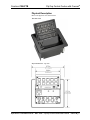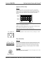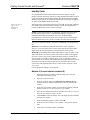
1
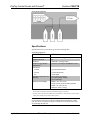
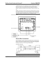
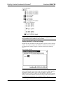
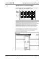
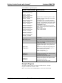
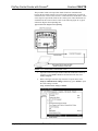
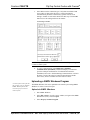
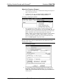
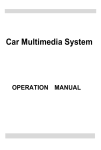
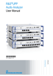
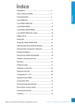
Crestron C2N-FTB
FlipTop Control Center with Cresnet®
Operations & Installation Guide
This document was prepared and written by the Technical Documentation department at:
Crestron Electronics, Inc.
15 Volvo Drive
Rockleigh, NJ 07647
1-888-CRESTRON
All brand names, product names and trademarks are the property of their respective owners.
©2005 Crestron Electronics, Inc.
FlipTop Control Center with Cresnet®
Crestron C2N-FTB
Contents
FlipTop Control Center with Cresnet®: C2N-FTB
1
Introduction ..........................................................................................................1
Features and Functions...........................................................................1
Specifications .........................................................................................2
Physical Description...............................................................................3
Industry Compliance ..............................................................................6
Setup.....................................................................................................................6
Network Wiring .....................................................................................6
Identity Code..........................................................................................8
Installation............................................................................................10
Hardware Hookup ................................................................................15
Ground Wire Connections....................................................................16
Configuration Software ......................................................................................17
Earliest Version Software Requirements for the PC ............................17
Configuring with Crestron SystemBuilder...........................................18
Configuring with SIMPL Windows .....................................................18
Example Program.................................................................................22
Uploading and Upgrading ..................................................................................23
Communication Settings ......................................................................23
Uploading a SIMPL Windows Program ..............................................25
Firmware Upgrade ...............................................................................27
Problem Solving .................................................................................................29
Further Inquiries...................................................................................29
Future Updates .....................................................................................29
Return and Warranty Policies.............................................................................30
Merchandise Returns / Repair Service .................................................30
CRESTRON Limited Warranty ...........................................................30
Operations & Installation Guide – DOC. 6338
Contents • i
FlipTop Control Center with Cresnet®
Crestron C2N-FTB
FlipTop Control Center
with Cresnet®: C2N-FTB
Introduction
Features and Functions
The C2N-FTB-B and the C2N-FTB-BALUM are Crestron® keypad devices that
provide a stylish flush-mount tabletop interface and control solution. The fliptop
compartment provides organized storage for a variety of pullout computer,
communication, and A/V cables, which stow neatly out of sight within the
fliptop compartment when not in use. The keypad provides A/V, lighting, and
other functional controls via Cresnet®.
The suffix ‘-B’, and ‘-BALUM’, respectively denotes color, e.g., C2N-FTB-B is
a black unit, and C2N-FTB-BALUM has a brushed aluminum finish. For
simplicity within this guide, color suffix is omitted and the designation
C2N-FTB is used except where noted.
Functional Summary
•
Built-in engravable* keypad with 10 to 20 buttons with LEDs
•
One AC power passthrough connector
•
Two Cresnet ports (on the bottom side)
•
Cable support plate (included)
* As an option, custom-engraved buttons can be designed and obtained by using the
Crestron Engraver software. They are available from the Crestron website.
Operations & Installation Guide – DOC. 6338 FlipTop Control Center with Cresnet®: C2N-FTB • 1
FlipTop Control Center with Cresnet®
Crestron C2N-FTB
C2N-FTB Block Diagram
Specifications
Specifications for the C2N-FTB are given in the following table.
C2N-FTB Specifications
SPECIFICATION
DETAILS
Cresnet Power Usage
2 Watts (0.082 Amp @ 24 VDC)
Default Network ID
1E
Firmware
C2N-FTB.V.1.00.upg or later
2-Series Control System
Update Files1,2
Version 3.125.CUZ (for QM-RMCRX) or later
Connectors
Cresnet
(2) 4-pin terminal blocks
Ground
(1) Ground Terminal
AC
(1) AC Outlet
Operating Temperature and
Humidity
41º to 104º F (5º to 40º C)
10 to 90% relative humidity
(non-condensing)
Dimensions and Weight
Width: 6.75 in (17.13 cm)
Height: 5.39 in (13.68 cm) with top closed
Depth: 5.71 in (14.49 cm)
Weight: 3.75 lbs (1.70 kg)
1. The latest software versions can be obtained from the Crestron website
(www.crestron.com/updates). Refer to the NOTE following these footnotes.
2. Crestron 2-Series control systems include the AV2 and PRO2. Consult the latest Crestron Product
Catalog for a complete list of 2-Series control systems.
NOTE: Crestron software and any files on the website are for Authorized
Crestron dealers and Crestron Authorized Independent Programmers (CAIP)
only. New users are required to register to obtain access to certain areas of the
site (including the FTP site).
2 • FlipTop Control Center with Cresnet®: C2N-FTB
Operations & Installation Guide - DOC. 6338
FlipTop Control Center with Cresnet®
Crestron C2N-FTB
Physical Description
Refer to the physical views shown below.
Top Open View
Physical Dimensions - Top View
Operations & Installation Guide – DOC. 6338 FlipTop Control Center with Cresnet®: C2N-FTB • 3
FlipTop Control Center with Cresnet®
Physical Dimensions - Front View
Crestron C2N-FTB
Bottom View
Back View
4 • FlipTop Control Center with Cresnet®: C2N-FTB
Side View
Operations & Installation Guide - DOC. 6338
FlipTop Control Center with Cresnet®
Crestron C2N-FTB
Controls and Ports (Top)
Buttons
The C2N-FTB can have 10 to 20 engravable, replaceable, programmable
buttons. All buttons are functionally identical and have light emitting diodes
(LEDs) that serve as user feedback indicators. The illumination of each LED
(on/off) is independently addressable, and programmable using SIMPL
Windows.
Row 1
Row 2
1
2
3
4
5
6
7
8
9
10
Row 3
Row 4
11
12
13
14
15
16
17
18
19
20
PWR
NET
NOTE: Numbers in this illustration are for programming purposes only. Refer
to page 21 for programming information.
NOTE: The C2N-FTB is shipped with a set of ten buttons. Additional buttons
may be added by ordering button kits (refer to page 10).
NOTE: These button units do not support audio WAV files.
AC Outlet
125V – 50/60Hz 10A
The 3-prong grounded AC outlet is rated at 125 VAC @ 10 Amps, 50 – 60 Hz.
Ports (Underside)
NET (x2)
NET
24 Y Z G
NET
24 Y Z G
These two 4-pin terminal block connectors, located on the bottom side of the
C2N-FTB, are for connection to the Cresnet network. One connector is used to
connect to the Cresnet network while the second connector can be used to
connect another Cresnet device. Cresnet power to the C2N-FTB is supplied
through either of these connectors. For more information, refer to “Network
Wiring” on page 6.
AC Power
Connect the six-foot (183 cm) grounded AC line cord to supply AC power to the
outlet on the topside of the C2N-FTB.
125V – 50/60Hz 10A
Operations & Installation Guide – DOC. 6338 FlipTop Control Center with Cresnet®: C2N-FTB • 5
FlipTop Control Center with Cresnet®
Crestron C2N-FTB
Indicators
PWR (Power)
This LED illuminates when 24 volts DC is supplied to the C2N-FTB from
Cresnet.
NET
This LED illuminates when communication between the control system and the
C2N-FTB is established (the unit is polled on the network). Illumination
indicates that the SIMPL Windows program currently loaded has a network
device defined at the same Net ID as the C2N-FTB.
Bargraphs
Two sets of eight-segment programmable red LEDs are provided that can be
programmed to display audio level settings. The LEDs display is proportional to
the input and can be set from zero to 100%.
SETUP LED and Pushbutton
The C2N-FTB is Touch-Settable ID-ready. A SETUP pushbutton is located on
the bottom side of the C2N-FTB. The SETUP pushbutton and its associated
LED are used for setting a units network ID during the initial configuration of a
Cresnet system or when the device is being added/replaced. Refer to “Method B
(Touch Settable ID)” on page 9 for detailed information.
Industry Compliance
As of the date of manufacture, the C2N-FTB has been tested and found to
comply with specifications for CE marking and standards per EMC and
Radiocommunications Compliance Labelling.
NOTE: This device complies with part 15 of the FCC rules. Operation is
subject to the following two conditions: (1) this device may not cause harmful
interference, and (2) this device must accept any interference received, including
interference that may cause undesired operation.
Setup
Network Wiring
CAUTION: In order to ensure optimum performance over the full range of
your installation topology, Crestron Certified Wire, and only Crestron Certified
Wire, should be used. Failure to do so, may incur additional charges if support is
required to identify performance deficiencies as a result of using improper wire.
CAUTION: Provide sufficient power to the system. Insufficient power can lead
to unpredictable results or damage to the equipment. Please use the Crestron
Power Calculator to help calculate how much power is needed for the system
(http://www.crestron.com/calculators).
6 • FlipTop Control Center with Cresnet®: C2N-FTB
Operations & Installation Guide - DOC. 6338
FlipTop Control Center with Cresnet®
Crestron C2N-FTB
CAUTION: Use only Crestron power supplies for Crestron equipment. Failure
to do so could cause equipment damage or void the Crestron warranty.
NOTE: When installing network wiring, refer to the latest revision of the
wiring diagram(s) appropriate for your specific system configuration, available
from the Crestron website.
When calculating the wire gauge for a particular Cresnet run, the length of the
run and the Cresnet power usage of each network unit to be connected must be
taken into consideration. If Cresnet units are to be daisy-chained on the run, the
Cresnet power usage of each unit to be daisy-chained must be added together to
determine the Cresnet power usage of the entire chain. If the unit is a home-run
from a Crestron system power supply network port, the Cresnet power usage of
that unit is the Cresnet power usage of the entire run. The length of the run in
feet and the Cresnet power usage of the run should be used in the resistance
equation below to calculate the value on the right side of the equation.
Resistance Equation
The required wire gauge should be chosen such that the resistance value is less
than the value calculated in the resistance equation. Refer to the following table.
Wire Gauge Values
RESISTANCE
WIRE GAUGE
4
16
6
18
10
20
15
22
13
Doubled CAT5
8.7
Tripled CAT5
NOTE: All Cresnet wiring must consist of two twisted pairs. One twisted pair
is the +24V conductor and the GND conductor, and the other twisted pair is the
Y conductor and the Z conductor.
NOTE: When daisy-chaining Cresnet units, strip the ends of the wires carefully
to avoid nicking the conductors. Twist together the ends of the wires that share a
pin on the network connector, and tin the twisted connection. Apply solder only
to the ends of the twisted wires. Avoid tinning too far up the wires or the end
becomes brittle. Insert the tinned connection into the Cresnet connector and
tighten the retaining screw. Repeat the procedure for the other three conductors.
NOTE: For additional information on video connections over CAT5, refer to
the latest version of the Crestron CAT5 Wiring Reference Guide (Doc. 6137)
which is available from Crestron website (http://www.crestron.com/manuals).
NOTE: For larger networks (i.e., greater than 28 network devices), it may be
necessary to add a Cresnet Hub/Repeater (CNXHUB) to maintain signal quality
throughout the network. Also, for networks with lengthy cable runs or varying
types of network devices, it may be desirable to add a hub/repeater after only 20
network devices.
Operations & Installation Guide – DOC. 6338 FlipTop Control Center with Cresnet®: C2N-FTB • 7
FlipTop Control Center with Cresnet®
Crestron C2N-FTB
Identity Code
Every equipment and user interface within the network requires a unique
identity code (Net ID). These codes are two-digit hexadecimal numbers from 03
to FE. The Net ID of each unit must match an ID code specified in the SIMPL
Windows program. Refer to “Setting the Net ID in Device Settings” on page 20
for details of the SIMPL Windows procedure
Refer to the note on
page 23 for a
definition of
Viewport.
The Net ID of the C2N-FTB has been factory set to 1E. The Net IDs of multiple
C2N-FTBs in the same system must be unique. Net IDs are changed from a
personal computer (PC) via the Crestron Viewport.
NOTE: For detailed information on establishing communication between the
PC and control system, refer to “Communication Settings” on page 23. If
communication cannot be established, refer to the “Troubleshooting
Communications” section in the latest version of the 2-Series Control System
Reference Guide (Doc. 6256), which is available from the Crestron website.
There are two different methods—Method A or Method B—for setting the Net
ID:
Method A (Cresnet address-settable ID), described as follows, applies to
devices in a Cresnet system with a 2-Series control system and requires that a
single unit be the only network device connected to the control system.
Method B (Touch Settable ID or TSID), which begins on page 9, applies to all
TSID-ready devices in a Cresnet system with 2-Series control system upgrade
file (CUZ) version 3.029 or later. TSID functionality makes it possible for the
control system to recognize a network device via its serial number, which is
stored in the device’s memory. This method does not require that any devices be
disconnected from the network; Net IDs may be set with the entire Cresnet
system intact. This method requires the use of the Crestron Viewport version
3.35 or later.
Use the appropriate method to set the Net ID.
Method A (Cresnet address-settable ID)
1.
Ensure that the device requiring a Net ID change is the only unit
connected to the control system.
2.
Open the Crestron Viewport.
3.
From the Viewport menu, select Functions | Set Network ID. The
software checks the baud rate and then opens the "Set Network ID"
window.
4.
In the "Set Network ID" window, select the device requiring a Net ID
change from the Current Network Devices text window.
5.
Select the new Net ID for the device from the Choose the new network
ID for the selected device (Hex): text box.
6.
Click Set ID to initiate the change. This will display the "ID command
has been sent" window.
7.
In the "Command Complete" window, click OK.
8.
In the Current Network Devices text window, verify the new Net ID
code.
9.
In the "Set Network ID" window, click Close.
8 • FlipTop Control Center with Cresnet®: C2N-FTB
Operations & Installation Guide - DOC. 6338
FlipTop Control Center with Cresnet®
Crestron C2N-FTB
NOTE: The new Net ID code may also be verified by selecting Diagnostic |
Report Network Devices in the Viewport (alternately, select F4).
10. Repeat this procedure for each additional network device requiring a
Net ID change.
Method B (Touch Settable ID)
Before using this method, you should have a list of all current network devices
and their Net IDs, to avoid assigning duplicate IDs.
Set Net ID by TSID
These procedures are for TSID-enabled network devices during the initial
configuration of a Cresnet system or when such devices are being
added/replaced.
1.
Ensure that all network devices are connected to the control system.
2.
Open the Crestron Viewport version 3.35 or later.
3.
From the Viewport menu, select Functions | Assign Cresnet ID by
Serial Number. The “Set Net ID by TSID” window appears. The
window is first displayed with the data fields empty.
4.
Click the Search for Touch Settable Devices button. The system
searches the network and lists all TSID-enabled devices found. The list
is similar to the report produced by pressing F4 (Report Network
Devices); the first eight digits of each line constitute the TSID number
(hexadecimal form of the serial number).
“Set Net ID by TSID” Window
5.
Enter either the serial number or TSID number of the device that
requires a change. The list scrolls to and highlights the device listing.
The listing should show the device’s default Cresnet ID (a.k.a. Net ID).
6.
Enter the Cresnet ID that the device should be set to and click OK. The
number you enter should appear on the list.
Operations & Installation Guide – DOC. 6338 FlipTop Control Center with Cresnet®: C2N-FTB • 9
FlipTop Control Center with Cresnet®
Crestron C2N-FTB
CAUTION: This function does not prevent you from setting duplicate IDs. Be
sure to check current assignments before entering the desired Cresnet ID
number.
Serial Number to TSID Conversion
This utility is useful in a case where there are multiple devices of the same type
on a network, you need to locate a particular one, you know the TSID but not
the serial number, and your site installation list is based on device serial
numbers. In this (or the reverse) situation, do the following:
1.
Open the Crestron Viewport.
2.
From the Viewport menu, select Functions | Serial Number ÅÆ
TSID Conversion Tool. The “Serial Number ÅÆTSID Conversion
Tool” window is displayed.
“Serial Number to TSID Conversion Tool” Window
3.
Enter the serial number or TSID number as instructed; press the
appropriate button to obtain the corresponding number.
NOTE: Enter serial numbers, including spaces, exactly as they appear on the
unit label. Alpha characters in serial numbers or TSID numbers may be entered
in upper or lower case.
Installation
The C2N-FTB is shipped with ten large blank buttons. You can order a variety
of button kits (sold separately) to add as many as 20 engraved or blank buttons.
Button Kits
KIT NUMBER
DESCRIPTION
FT-BTNB-L
One large button engraved as desired
FT-BTNB-L-BLANK
One large button not engraved
FT-BTNB-S
Two small buttons with divider engraved as desired
FT-BTNB-S-BLANK
Two small buttons with divider, not engraved
Button Installation
To replace the large buttons with small buttons, follow this procedure.
A 1/16" Allen (hexhead) wrench is required to remove the button faceplate.
10 • FlipTop Control Center with Cresnet®: C2N-FTB Operations & Installation Guide - DOC. 6338
FlipTop Control Center with Cresnet®
Crestron C2N-FTB
1.
Remove the four Allen screws that secure the button faceplate.
2.
While holding adjacent buttons in place, carefully pull the button(s) to
be replaced from the rubber membrane.
3.
Carefully press the two small replacement buttons in place, making
sure LED window faces up. Use care not to dislodge the membrane and
circuit board.
CAUTION: The removable buttons fit snugly on the rubber membrane and
must be removed carefully to avoid pulling the membrane from the unit. Once
membrane is detached, you may be unable to reattach it.
4.
The divider bar slips into the slots on the back of the faceplate.
5.
Replace the faceplate.
Button Installation
Cable Management Plate
The C2N-FTB is shipped with a cable management plate that provides an eighthole plate for an easy pullout cable solution for computer, LAN and other
passthrough cables.
Parts Supplied with Cable Management Plate
PART DESCRIPTION
QUANTITY
Cable Bushing, 5/16” ID, 0.5” OD
4
Cable Bushing, 0.39” ID, 0.64” OD
2
Cable Bushing, 0.54” ID, 0.79” OD
2
Cable Support Plate (2011563)
1
#4-40 x ¼” L, Pan Head Phillips Black Mounting Screws
4
Operations & Installation Guide – DOC. 6338 FlipTop Control Center with Cresnet®: C2N-FTB • 11
FlipTop Control Center with Cresnet®
Crestron C2N-FTB
The cable management plate must be installed before mounting the C2N-FTB to
a surface. The cables are looped through the cable support plate.
A Phillips screwdriver is required to install the cable management plate.
1.
Place the bushings on the cables (eight bushings supplied).
2.
Thread the cables through the appropriate slot on the plate.
3.
Snap the bushings into the plate slots. The bushings protect the cables
from chafing against the metal edge of the plate.
4.
Feed all the excess cable through the opening.
5.
Use a Phillips screwdriver to attach the plate with the four #4-40 x ¼”
black screws.
6.
The cables may be secured to the bottom bar using tie wraps (not
supplied).
Cable Management Plate Installation
When selecting cables for installation in the C2N-FTB, cable connector length
and strain relief diameter are important considerations.
•
If the connector is too long, it can interfere with cover operation and
scratch the buttons.
•
If the width of the cable strain relief is too similar to the bushing inside
diameter, the bushing can trap the cable.
NOTE: Do not use the cable management plate without the bushings.
12 • FlipTop Control Center with Cresnet®: C2N-FTB Operations & Installation Guide - DOC. 6338
FlipTop Control Center with Cresnet®
Crestron C2N-FTB
Example Cable End
Cable Loops Through the Cable Management Plate
NOTE: Ensure that the cables have sufficient clearance to enable smooth
movement. Allow approximately 40 inches (102 cm) from the top surface of the
FlipTop box.
Mounting to Surface
The C2N-FTB is designed to mount in a horizontal surface, such as a desk top,
lectern, or podium. The following diagram illustrates the required opening size
to accommodate the C2N-FTB. A cutout template (4006405) is included.
Operations & Installation Guide – DOC. 6338 FlipTop Control Center with Cresnet®: C2N-FTB • 13
FlipTop Control Center with Cresnet®
Crestron C2N-FTB
Cutout Dimensions
6.375 in
(6 3/8 in)
(16.19 cm)
5.3125 in
(5 5/16 in)
(13.494 cm)
Maximum
Radius
0.125 in
(0.318 cm)
Mounting Parts Supplied with the C2N-FTB
PART DESCRIPTION
QUANTITY
#6-32, 3/16” Pan Head, Phillips Screw
8
#10-32, 2” Pan Head, Phillips Screw
4
Mounting Bracket
2
A Phillips screwdriver is required to mount the C2N-FTB to a surface.
NOTE: Before inserting the C2N-FTB in the mounting hole, ensure that all
required cables have been installed.
1.
Install the eight supplied #6-32 screws, but do not tighten (four on the
front side and four on the rear side). These will be used to secure the
front and rear mounting brackets.
2.
Position the C2N-FTB in the mounting hole.
Mounting Bracket Screw Locations
14 • FlipTop Control Center with Cresnet®: C2N-FTB Operations & Installation Guide - DOC. 6338
FlipTop Control Center with Cresnet®
Crestron C2N-FTB
3.
Install the four #10 screws in the mounting brackets (two screws per
bracket). Refer to the following diagram.
4.
Slide the mounting brackets over the #6-32 screws and tighten the
#6-32 screws using a Phillips screwdriver.
5.
Use a Phillips screwdriver to turn the four #10 screws equally until they
contact the underside of the mounting surface.
NOTE: Do not over-tighten the #10 screws as this may damage the surface
and/or the unit.
Mounting Bracket Installation
NOTE: Be careful not to press the buttons while closing the FlipTop, even
though the buttons are disabled when the FlipTop begins to close and all pressed
buttons are released.
Hardware Hookup
Refer to the following hookup diagram and, aside from attaching power last,
complete the connections in any order.
NOTE: To prevent overheating, do not operate this product in an area that
exceeds the environmental temperature range listed in the specifications table.
Operations & Installation Guide – DOC. 6338 FlipTop Control Center with Cresnet®: C2N-FTB • 15
FlipTop Control Center with Cresnet®
Crestron C2N-FTB
Consideration must be given if installed in a closed or multi-unit rack assembly,
inside a closed desk, or in a closed podium since the operating ambient
temperature of these environments may be greater than the room ambient.
Contact with thermal insulating materials should be avoided on all sides of the
unit.
NOTE: The maximum continuous current from equipment under any external
load conditions shall not exceed a current limit that is suitable for the minimum
wire gauge used in interconnecting cables. The ratings on the connecting unit's
supply input should be considered to prevent overloading the wiring.
Underside Connections
Ground Wire Connections
Proper grounding is required. Connect the ground from the C2N-FTB to earth
ground. Connect the Cresnet shield lead at the control processor to the ground
lead. The control processor chassis must also be connected to an earth ground
(building steel). Refer to the following grounding diagram.
Ground Wire Connections
NOTE: Do not connect the shield to earth ground at the C2N-FTB
16 • FlipTop Control Center with Cresnet®: C2N-FTB Operations & Installation Guide - DOC. 6338
FlipTop Control Center with Cresnet®
Crestron C2N-FTB
Configuration Software
Have a question or comment about Crestron software?
Answers to frequently asked questions (FAQs) can be viewed in the Online Help
section of the Crestron website. To post a question or view questions you have
submitted to Crestron’s True Blue Support, log in at http://support.crestron.com.
First-time users will need to establish a user account.
Configuration is easy thanks to Crestron’s Windows-based programming
software. Crestron SystemBuilder™ software creates a complete project, with
no special programming required. SystemBuilder completes all necessary
programming for a base system including all touchpanel screens and the control
system program. The program output of SystemBuilder is a SIMPL Windows
program with much of the functionality encapsulated in macros and templates.
Once SystemBuilder creates the project, the system interfaces and program logic
can be customized in SystemBuilder or can be easily modified with Crestron
development tools (i.e., SIMPL Windows and Crestron VisionTools® Pro-e (VT
Pro-e) software packages).
SystemBuilder comes with templates for all supported interfaces. If a user
wishes to create a touchpanel project using templates with a different look-andfeel, this can be accomplished by making a custom template. This custom
template can then be used by SystemBuilder to create the final project files to be
loaded into the panels. Alternatively, VT Pro-e can be used to tweak projects
created with the SystemBuilder or develop original touchpanel screen designs.
Earliest Version Software Requirements for the
PC
NOTE: Crestron recommends that you use the latest software to take advantage
of the most recently released features. The latest software is available from the
Crestron website.
NOTE: Crestron software and any files on the website are for Authorized
Crestron dealers and Crestron Authorized Independent Programmers (CAIP)
only. New users are required to register to obtain access to certain areas of the
site (including the FTP site).
The following are the earliest useable software version requirements for the PC:
•
(Optional but highly recommended) SystemBuilder version 2.0
(Requires SIMPL Windows, VT Pro-e and Crestron database).
•
SIMPL Windows version 2.05.22 or later. Library 320 and SIMPL+®
Cross Compiler version 1.1 are required.
•
Crestron Database version 16.4.1 or later. Required by SIMPL
Windows.
•
(Optional, if system was programmed without SystemBuilder 2.0)
Installer’s Toolbox version 1.0 or Viewport version 3.35.
•
Crestron Engraver version 2.3 for button engraving.
Operations & Installation Guide – DOC. 6338 FlipTop Control Center with Cresnet®: C2N-FTB • 17
FlipTop Control Center with Cresnet®
Crestron C2N-FTB
Configuring with Crestron SystemBuilder
The Crestron SystemBuilder interface guides you through a few basic steps for
specifying the control system, designating rooms and touchpanels, devices, and
functionality. The Crestron SystemBuilder then configures the system, including
all touchpanel projects and control system logic. It can also connect to Crestron
RoomView™ management software.
The Crestron SystemBuilder is fully integrated with the Crestron suite of
software development tools, including SIMPL Windows, Cross Compiler, VT
Pro-e, Crestron Database, User IR Database, and User Modules Directory. The
Crestron SystemBuilder accesses all these tools behind the scenes, enabling you
to easily create robust systems.
SystemBuilder provides a step-by-step process that guides the user through the
process of selecting components and determining signal routing and control. The
control code and complete equipment lists are automatically generated. Crestron
SystemBuilder automatically compiles and uploads your program to the control
system.
SystemBuilder
After entering the appropriate information in each step, SystemBuilder creates
the control system logic and touchpanel pages, ready to upload to the controller.
NOTE: Crestron SystemBuilder version 2.0 or higher is required.
For additional details, download SystemBuilder from the Crestron website and
examine the extensive help file.
Configuring with SIMPL Windows
NOTE: The following are acceptable file extensions for programs that include
a C2N-FTB, developed for specific control system types:
.smw projectname.smw (source file)
.spz projectname.spz (compiled file for 2-Series)
.usp projectname.usp (source code module for SIMPL+)
.ir
projectname.ir (user IR)
.umc projectname.umc (user macro)
.ush projectname.ush (completed SIMPL+)
18 • FlipTop Control Center with Cresnet®: C2N-FTB Operations & Installation Guide - DOC. 6338
Crestron C2N-FTB
FlipTop Control Center with Cresnet®
SIMPL Windows is the Crestron graphical, Windows®-based development tool
for programming control systems. The SIMPL Windows interface provides two
workspaces: the Configuration Manager, for configuring the control system,
touchpanels, and controlled network devices; and Program Manager, for
designing the logic and functionality of the control system.
In addition, you can use the powerful Crestron Viewport utility to accomplish
multiple system tasks, such as uploading the program to the control system and
performing diagnostic functions.
NOTE: The information in this section assumes that the reader has knowledge
of SIMPL Windows. If not, refer to the extensive help information provided
with the software.
NOTE: In the following description, the PRO2 control system is used.
This section describes a sample SIMPL Windows program that includes a
C2N-FTB.
Configuration Manager is where programmers “build” a Crestron control system
by selecting hardware from the Device Library. In Configuration manager, drag
the PRO2 from the Control Systems folder of the Device Library and drop it in
the upper pane of the System Views. The PRO2 with its associated
communication ports is displayed in the System Views upper pane.
PRO2 System View
The System Views lower pane displays the PRO2 system tree (refer to the
following graphic). This tree can be expanded to display and configure the
communication ports.
Expanded PRO2 System Tree
C2Net-Device Slot in Configuration Manager
To incorporate a C2N-FTB into the system, drag the C2N-FTB from the Wired
Keypad folder of the Device Library and drop it in System Views. The PRO2
system tree displays the C2N-FTB in Slot 9, with a default Net ID of 1E as
shown in the following illustration.
Operations & Installation Guide – DOC. 6338 FlipTop Control Center with Cresnet®: C2N-FTB • 19
FlipTop Control Center with Cresnet®
Crestron C2N-FTB
A C2N-FTB in Slot 9
NOTE: The first C2N-FTB in a system is preset with a Net ID of 1E when its
symbol is dragged into the upper pane of System Views. Additional units are
assigned different Net ID numbers as they are added.
Setting the Net ID in Device Settings
Double-click the C2N-FTB icon in the upper pane to open the “Device Settings”
window. This window displays C2N-FTB device information. The Net ID can
be changed in this window using the Net ID tab, as shown in the following
figure.
“Device Settings” Window
NOTE: This procedure sets the Net ID for the C2N-FTB in the program only. It
does not automatically set the Net ID for the C2N-FTB itself. SIMPL Windows
automatically changes Net ID values of a device added to a program if a
duplicate device or a device with the same Net ID already exists in the program.
Always ensure that the hardware and software settings of the Net ID match. For
Net ID hardware setting details, refer to “Identity Code” on page 8.
20 • FlipTop Control Center with Cresnet®: C2N-FTB Operations & Installation Guide - DOC. 6338
FlipTop Control Center with Cresnet®
Crestron C2N-FTB
C2N-FTB Symbol in Programming Manager
The Buttons module is built into the C2N-FTB. It consists of a 10 to 20 button
keypad with LED indicators, and two bargraphs. The button presses are fixed
and map to <press> outputs on the symbol detail, as follows:
Row 1
Row 2
1
2
3
4
5
6
7
8
9
10
Row 3
Row 4
11
12
13
14
15
16
17
18
19
20
PWR
NET
NOTE: Numbers in this illustration are for programming purposes only.
The buttons on rows 1 and 2 can be combined vertically to form one larger
button. For example, the button caps for buttons #1 and #6 can be replaced with
one larger button cap. Similarly, the vertical pairs on rows 3 and 4 can be
combined to form one larger button. For example, buttons #13 and #18 can be
combined. No other combinations are valid. That is, two buttons cannot be
combined horizontally; the buttons on rows 2 and 3 cannot be combined.
Programming Manager is where programmers “program” a Crestron control
system by assigning signals to symbols. The following diagram shows the
C2N-FTB symbol in the SIMPL Windows’ Programming Manager.
C2N-FTB Symbol – Detail View of Buttons
Operations & Installation Guide – DOC. 6338 FlipTop Control Center with Cresnet®: C2N-FTB • 21
FlipTop Control Center with Cresnet®
Crestron C2N-FTB
C2N-FTB Buttons – Signal Descriptions
SIGNAL TYPE AND NAME
DESCRIPTION
Digital Outputs:
Button presses/vertical pair
<Press1>, <Press6>
Button presses/vertical pair
<Press2>, <Press7>
Button presses/vertical pair
<Press3>, <Press8>
Button presses/vertical pair
<Press4>, <Press9>
Button presses/vertical pair
<Press5>, <Press10>
Button presses/vertical pair
<Press11>, <Press16>
Button presses/vertical pair
<Press12>, <Press17>
Button presses/vertical pair
<Press13>, <Press18>
Indicates that the corresponding button has been
pressed. The signal remains high for the duration
of the button press.
If the FlipTop cover is not fully open the buttons
are disabled and the unit will not report any button
presses, and will release any button that is already
pressed. The status of the cover is given by the
<FlipTopOpen> output.
If two buttons are combined to form one larger
button, the same signal should be attached to both
button presses.
High/1 = Button pressed
Low/0 = Button released
Button presses/vertical pair
<Press14>, <Press19>
Button presses/vertical pair
<Press15>, <Press20>
Digital Inputs:
<fb1> through <fb20>
Activates the corresponding LED for as long as the
input is high.
If two buttons are combined, then only the LED for
the top button in the vertical pair will be visible.
High/1 (level sensitive) = Activate LED feedback
Low/0 = Turn off LED
Digital Output:
<FlipTopOpen>
Indicates that the FlipTop cover is fully open. The
feedback remains high for as long as the cover is
open.
If the cover is not fully open the signal will go low,
the keypad buttons will be disabled and the unit
will not report any button presses.
High/1 = FlipTop open
Low/0 = FlipTop not fully open
Analog Input:
<Bargraph1>
Sets the levels that will be displayed on the left
bargraph. The bargraph is an 8-segment LED and
is proportional to the input.
Valid values range from 0% to 100%.
Analog Input:
<Bargraph2>
Sets the levels that will be displayed on the right
bargraph. The bargraph is an 8-segment LED and
is proportional to the input.
Valid values range from 0% to 100%.
Example Program
An example program for the C2N-FTB is available from the “Example
Program” section of the Crestron website
(http://www.crestron.com/exampleprograms). Search for C2N-FTB.ZIP.
22 • FlipTop Control Center with Cresnet®: C2N-FTB Operations & Installation Guide - DOC. 6338
FlipTop Control Center with Cresnet®
Crestron C2N-FTB
Uploading and Upgrading
NOTE: Crestron recommends that you use the latest software and that each
device contains the latest firmware to take advantage of the most recently
released features. Please check the Crestron website
(http://www.crestron.com/updates) for the latest versions of software and
firmware. New users are required to register to obtain access to this site.
Assuming a PC is properly connected to the entire system, Crestron
programming software allows the programmer to upload programs and projects
to the system and touchpanel and firmware to the wall plates after their
development. However, there are times when the files for the program and
projects are compiled and not uploaded. Instead, compiled files may be
distributed from programmers to installers, from Crestron to dealers, etc. Even
firmware upgrades are available from the Crestron website as new features are
developed after product releases. In those instances, one has the option to upload
via the programming software or to upload and upgrade via the Crestron
Viewport.
NOTE: The Crestron Viewport is available as a pull-down command from
SIMPL Windows and VT Pro-e (Tools | Viewport) or as a standalone utility.
The Viewport utility performs multiple system tasks, primarily via an RS-232 or
TCP/IP connection between the control system and a PC. It is used to observe
system processes, upload new operating systems and firmware, change system
and network parameters, and communicate with network device consoles and
touchpanels, among many other tasks. Viewport can also function as a terminal
emulator for generic file transfer. All of these functions are accessed through the
commands and options in the Viewport menus. Therefore, for its effectiveness
as a support and diagnostic tool, the Crestron Viewport may be preferred over
development tools when uploading programs and projects.
The following sections define how one would upload a SIMPL Windows
program to the control system, or upgrade the firmware of the C2N-FTB.
However, before attempting to upload or upgrade, it is necessary to establish
communications.
Communication Settings
NOTE: For laptops and other PCs without a built-in RS-232 port, Crestron
recommends the use of PCMCIA cards, rather than USB-to-serial adapters. If a
USB-to-serial adapter must be used, Crestron has tested the following devices
with good results:
Belkin (large model) F5U103
I/O Gear GUC232A (discontinued)
Keyspan USA-19QW (discontinued)
Other models, even from the same manufacturer, may not yield the same results.
NOTE: Even with these recommended models, results may vary on the
computer being used.
Operations & Installation Guide – DOC. 6338 FlipTop Control Center with Cresnet®: C2N-FTB • 23
FlipTop Control Center with Cresnet®
Crestron C2N-FTB
The procedure in this section provides details for RS-232 communication
between the PC and the control system. If TCP/IP communication is preferred,
consult the latest version of the Crestron e-Control Reference Guide (Doc. 6052)
or the respective Operations Guide for the control system. These documents are
available from the Crestron website. Refer to the following figure for a typical
connection diagram when uploading files.
Typical Connection Diagram when Uploading
NOTE: Use a standard DB9 “Null-Modem” cable.
1.
Open the Crestron Viewport. Either launch the stand-alone version of
Viewport, or start SIMPL Windows and from the menu bar, select
Tools | Viewport.
2.
Refer to the figure after this step. From the Viewport menu, select
Setup | Communications settings (alternatively, press Alt+D) to open
the “Port Settings” window.
Setup | Communications Settings Command
24 • FlipTop Control Center with Cresnet®: C2N-FTB Operations & Installation Guide - DOC. 6338
FlipTop Control Center with Cresnet®
Crestron C2N-FTB
3.
Select RS-232 as the connection type. Verify that an available COM
port (COM 1 is shown after this step) is selected, and that all
communication parameters and necessary options from the “Port
Settings” window are selected as shown after this step. Click the OK
button to save the settings and close the window.
“Port Settings” Window
NOTE: The parameters shown in the illustration above are the port settings for
a 2-Series control system.
4.
To verify communication, select Diagnostics | Establish
Communications (Find Rack). This should display a window that
gives the COM port and baud rate. If communication cannot be
established, refer to the “Troubleshooting Communications” section in
the latest version of the 2-Series Control System Reference Guide
(Doc. 6256), which is available from the Crestron website.
Uploading a SIMPL Windows Program
A control system source file has
the extension .smw. A compiled
SIMPL Windows file has the
extension .spz for a 2-Series
control system.
The SIMPL Windows file can be uploaded to the control system using SIMPL
Windows or via the Crestron Viewport.
Upload via SIMPL Windows
1.
Start SIMPL Windows.
2.
Select File | Open to view the “Open” window, navigate to the SIMPL
Window file (.smw), and click Open.
3.
Select Project | Transfer Program.
Operations & Installation Guide – DOC. 6338 FlipTop Control Center with Cresnet®: C2N-FTB • 25
FlipTop Control Center with Cresnet®
Crestron C2N-FTB
Upload via Crestron Viewport
1.
Verify that the procedure for “Communication Settings” that begins on
page 23 has been performed.
2.
As shown after this step, select File Transfer | Send Program
(alternatively, press Alt+P) from the Viewport menu bar.
File Transfer | Send Program Command
3.
The “Send Program” window appears, as shown on the next page.
Click Browse, locate the compiled file (.spz) and click Open. This will
display the program's header information and enable one or both of the
What to Send check boxes. If the program does not contain any
SIMPL+ modules, only the SIMPL Program check box will be enabled.
If it does contain SIMPL+ modules, then the SIMPL+ Program(s)
check box will also be enabled. Select one or both check boxes and
then click Send Program to begin the transfer.
NOTE: Refer to the latest version of the Crestron 2-Series Control System
Reference Guide (Doc. 6256) for details about the other fields shown on the
“Send Program” window.
“Send Program” Window
4.
To verify that the program has been transferred successfully, select
Diagnostics | Report Program Information. This should display a
window that provides details about the current program loaded into the
control system.
26 • FlipTop Control Center with Cresnet®: C2N-FTB Operations & Installation Guide - DOC. 6338
FlipTop Control Center with Cresnet®
Crestron C2N-FTB
Firmware Upgrade
A firmware upgrade
file has the extension .csf.
To take advantage of all the C2N-FTB features, it is important that the unit
contains the latest firmware available. Please check the Crestron website for the
latest version of firmware. Not every product has a firmware upgrade, but as
Crestron improves functions, adds new features, and extends the capabilities of
its products, firmware upgrades are posted. To upgrade the firmware, complete
the following steps.
NOTE: Viewport versions 3.80 or later have "Load Network Device
(Legacy)..." and "Update Network Device Firmware..." options. Either will
work with firmware version 1.00 but Crestron suggests using "Update Network
Device Firmware..." to load firmware updates.
NOTE: A firmware upgrade file has the extension .csf.
The following is the acceptable file extension for a firmware update file.
.upg
C2N-FTB.V.XXXXX.upg
1.
Make sure that “Communication Settings,” which begins on page 23,
has been performed.
2.
As shown after this step, select File Transfer | Update Network
Device Firmware… from the Viewport menu bar.
File Transfer | Update Network Device Firmware… Command
3.
As shown in the “Select Network ID” window, select the Net ID of the
C2N-FTB, and then click OK. The “Open” window appears (refer to
the following graphics).
Operations & Installation Guide – DOC. 6338 FlipTop Control Center with Cresnet®: C2N-FTB • 27
FlipTop Control Center with Cresnet®
Crestron C2N-FTB
“Select Network ID” Window
NOTE: If problems arise when transferring any Cresnet file (touchpanel
project/firmware), lower the port speed baud rate to 38400 to match the Cresnet
bus speed.
“Open” Window
4.
Browse to the desired [filename].upg file and click Open to begin the
transfer.
28 • FlipTop Control Center with Cresnet®: C2N-FTB Operations & Installation Guide - DOC. 6338
FlipTop Control Center with Cresnet®
Crestron C2N-FTB
Problem Solving
The following table provides corrective action for possible trouble situations. If
further assistance is required, please contact a Crestron customer service
representative.
C2N-FTB Troubleshooting
TROUBLE
C2N-FTB not
functioning.
PWR LED
does not
illuminate.
POSSIBLE
CAUSE(S)
CORRECTIVE ACTION
Net ID is not correct.
In Viewport, poll the network to
verify the Net ID.
Net ID is not set to match
the Net ID specified in
SIMPL Windows.
Verify SIMPL Windows program for
setting Net ID.
Net ID is the same as
another device’s Net ID.
Assign a different Net ID.
Not receiving power.
Verify that Cresnet is properly
attached.
Buttons do
not function
when
pressed.
Net ID incorrect or does
not match SIMPL
Windows program.
In Viewport, press F4 to verify Net
ID.
Verify SIMPL Windows program ID.
Button press
yields
incorrect
result.
Incorrect programming.
Verify SIMPL Windows program.
Button LED
does not
illuminate.
Feedback signal names
incorrect in SIMPL
Windows.
Verify SIMPL Windows feedback
signal names.
Further Inquiries
If you cannot locate specific information or have questions after reviewing this
guide, please take advantage of Crestron's award winning customer service team
by calling the Crestron corporate headquarters at 1-888-CRESTRON
[1-888-273-7876]. For assistance in your local time zone, refer to the Crestron
website (www.crestron.com) for a listing of Crestron worldwide offices.
You can also log onto the online help section of the Crestron website to ask
questions about Crestron products. First-time users will need to establish a user
account to fully benefit from all available features.
Future Updates
As Crestron improves functions, adds new features, and extends the capabilities
of the C2N-FTB, additional information may be made available as manual
updates. These updates are solely electronic and serve as intermediary
supplements prior to the release of a complete technical documentation revision.
Check the Crestron website periodically for manual update availability and its
relevance. Updates are identified as an “Addendum” in the Download column.
Operations & Installation Guide – DOC. 6338 FlipTop Control Center with Cresnet®: C2N-FTB • 29
FlipTop Control Center with Cresnet®
Crestron C2N-FTB
Return and Warranty Policies
Merchandise Returns / Repair Service
1.
No merchandise may be returned for credit, exchange, or service without prior
authorization from CRESTRON. To obtain warranty service for CRESTRON products,
contact the factory and request an RMA (Return Merchandise Authorization) number.
Enclose a note specifying the nature of the problem, name and phone number of contact
person, RMA number, and return address.
2.
Products may be returned for credit, exchange, or service with a CRESTRON Return
Merchandise Authorization (RMA) number. Authorized returns must be shipped freight
prepaid to CRESTRON, 6 Volvo Drive, Rockleigh, N.J. 07647, or its authorized
subsidiaries, with RMA number clearly marked on the outside of all cartons. Shipments
arriving freight collect or without an RMA number shall be subject to refusal.
CRESTRON reserves the right in its sole and absolute discretion to charge a 15%
restocking fee, plus shipping costs, on any products returned with an RMA.
3.
Return freight charges following repair of items under warranty shall be paid by
CRESTRON, shipping by standard ground carrier. In the event repairs are found to be
non-warranty, return freight costs shall be paid by the purchaser.
CRESTRON Limited Warranty
CRESTRON ELECTRONICS, Inc. warrants its products to be free from manufacturing defects in
materials and workmanship under normal use for a period of three (3) years from the date of
purchase from CRESTRON, with the following exceptions: disk drives and any other moving or
rotating mechanical parts, pan/tilt heads and power supplies are covered for a period of one (1)
year; touchscreen display and overlay components are covered for 90 days; batteries and
incandescent lamps are not covered.
This warranty extends to products purchased directly from CRESTRON or an authorized
CRESTRON dealer. Purchasers should inquire of the dealer regarding the nature and extent of the
dealer's warranty, if any.
CRESTRON shall not be liable to honor the terms of this warranty if the product has been used in
any application other than that for which it was intended, or if it has been subjected to misuse,
accidental damage, modification, or improper installation procedures. Furthermore, this warranty
does not cover any product that has had the serial number altered, defaced, or removed.
This warranty shall be the sole and exclusive remedy to the original purchaser. In no event shall
CRESTRON be liable for incidental or consequential damages of any kind (property or economic
damages inclusive) arising from the sale or use of this equipment. CRESTRON is not liable for
any claim made by a third party or made by the purchaser for a third party.
CRESTRON shall, at its option, repair or replace any product found defective, without charge for
parts or labor. Repaired or replaced equipment and parts supplied under this warranty shall be
covered only by the unexpired portion of the warranty.
Except as expressly set forth in this warranty, CRESTRON makes no other warranties, expressed
or implied, nor authorizes any other party to offer any warranty, including any implied warranties
of merchantability or fitness for a particular purpose. Any implied warranties that may be imposed
by law are limited to the terms of this limited warranty. This warranty statement supercedes all
previous warranties.
Trademark Information
All brand names, product names, and trademarks are the sole property of their respective owners. Windows is a registered
trademark of Microsoft Corporation. Windows95/98/Me/XP and WindowsNT/2000 are trademarks of Microsoft
Corporation.
30 • FlipTop Control Center with Cresnet®: C2N-FTB Operations & Installation Guide - DOC. 6338
Crestron C2N-FTB
FlipTop Control Center with Cresnet®
This page intentionally left blank.
Operations & Installation Guide – DOC. 6338 FlipTop Control Center with Cresnet®: C2N-FTB • 31
Crestron Electronics, Inc.
15 Volvo Drive Rockleigh, NJ 07647
Tel: 888.CRESTRON
Fax: 201.767.7576
www.crestron.com
Operations & Installation Guide – DOC. 6338
02.05
Specifications subject to
change without notice.