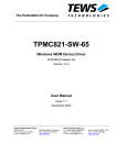
1
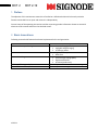
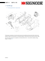
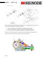
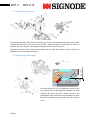
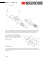
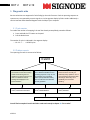
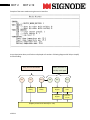
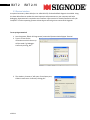
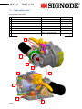
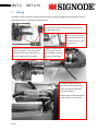
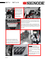
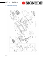
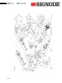
1 BXT 2 BXT 2-19 Maintenance Manual ak 03.11 2 BXT 2 BXT 2-19 Content: 1. Preface .................................................................................................................................................................. 3 2. Basic Innovations ................................................................................................................................................... 3 3. Tool Design............................................................................................................................................................ 4 3.1. Housing/electrical components: .................................................................................................................... 4 3.2. Welding unit .................................................................................................................................................. 5 3.3. Rocker lever and reset .................................................................................................................................. 6 3.4. Rocker and toothed plate .............................................................................................................................. 6 3.5. Tensioning gear ............................................................................................................................................ 7 3.6. Side cover with strap guides ......................................................................................................................... 7 4. Wear parts ............................................................................................................................................................. 7 5. Diagnostic aids ...................................................................................................................................................... 8 5.1. Cycle counter ................................................................................................................................................ 8 5.2. Problem reports............................................................................................................................................. 8 5.3. Service Interface ......................................................................................................................................... 11 6. Tool reset ............................................................................................................................................................. 14 7. Disassembling ..................................................................................................................................................... 15 7.1. Housing/electrical components ................................................................................................................... 15 7.2. Welding unit ................................................................................................................................................ 16 7.3. Rocker lever and reset ................................................................................................................................ 17 7.4. Tensioning gear .......................................................................................................................................... 18 8. Assembly ............................................................................................................................................................. 18 9. Adjustments ......................................................................................................................................................... 19 9.1. Adjustment of the welding reset .................................................................................................................. 19 10. Lubricating chart .............................................................................................................................................. 20 11. Wiring .............................................................................................................................................................. 21 12. Error Code List ................................................................................................................................................ 23 12.1. User Errors .................................................................................................................................................. 23 12.2. Device Error control system ........................................................................................................................ 24 12.3. Device error battery..................................................................................................................................... 25 12.4. Device Error Drive ....................................................................................................................................... 26 13. Wiring diagramm: ............................................................................................................................................ 28 14. Explosion drawing ........................................................................................................................................... 29 15. Product information ......................................................................................................................................... 33 16. Contact ............................................................................................................................................................ 33 ak 03.11 3 BXT 2 BXT 2-19 1. Preface The objective of this maintenance manual is to familiarize a skilled technician with the tools particular features and enable him to repair and maintain it independently. Current issues of the operating instructions and the concerning product information sheets are essential elements of this manual and have to be checked as well. 2. Basic Innovations Following new technical features have been implemented in this tool generation: Innovation Lithium-Ion battery technologie Brushles DC Motor Automatic welding Rocker with floating tooth plate Revised Tension release pawl ak 03.11 Advantage • • • • • • • • • • Increased energie density negligible self discharging no memory effect Higher Efficiency Wear-free Constant high sealing quality Ergonomic benefits Increased productivity Improved characteristics in tensioning Improved handling 4 BXT 2 BXT 2-19 3. Tool Design 3.1. Housing/electrical components: The housing is carried out in 3 pieces. All processes are controlled and monitored by the Printed circuit board (pos. 198). The PCB interacts via the signal cable (pos. 202) with the motor power electronics (pos. 212). The power electronics is required to run the brushless motor. You can find a schematic wiring diagram in chapter 13. ak 03.11 5 BXT 2 BXT 2-19 3.2. Welding unit The unit is lowering automatically when the welding process is started. Depending on the direction of motor rotation (freewheels) this is taking place as follows: 1. The cam ring (pos 109) is turning towards the switching cam (pos. 140, 143). 2. This forces the switching cam to go up and to push the welding unit downwards. 3. The eccentric axe (pos.155) is driving the welding shoe via needle bearing (pos.157) The position of the cam ring needs to be controlled by the PCB. The required information about its current position (reference point) is provided by the micro switch (pos. 103). 1. 2. 3. ak 03.11 BXT 2 BXT 2-19 3.3. Rocker lever and reset The Blocking Pawl (pos. 65) prevents the tension gear from turning backwards during tensioning. After strapping has taken place, the rocker lever (pos.89) is pulled, the pawl and therewith the tension is released. The reset cam (pos. 72) brings the welding unit back to its initial position. The Micro switch (Part of pos. 103) scans the position of the rocker lever. When the lever is pulled, the PCB does not allow initiating any function. 3.4. Rocker and toothed plate 0-0.1mm 6 46 44 53 The tooth plate (Pos. 53) is not tightened onto the rocker. This principle has the advantage that regardless the strap thickness the contact pressure is always consistent. The gap between tooth plate and the tension wheel (Pos. 46) is ensured by a bedstop on the cam disk, (Pos.44) notice the arrow. ak 03.11 7 BXT 2 BXT 2-19 3.5. Tensioning gear There is a free wheel integrated into the bevel gear pinion (Pos. 132). Provided the appropriate turning direction the free wheel delivers the torque to the 2 stage planetary gear and the tension wheel. To loose the tension the ring gear (Pos.19) is released by the pawl axle (Pos. 59). See also chapter 3.3). 3.6. Side cover with strap guides The strap guide (Pos. 179) is integrated into the side cover. To set up the required strap width the shims (Pos. 177, 178, 181) have to be added or removed. 4. Wear parts Tension wheel, toothed plate and knife are wear parts. In order to reduce costs for the enduser these parts can easily be replaced by themselves. The operating instructions provide the necessary information in chapter 7.1 – 7.3. ak 03.11 8 BXT 2 BXT 2-19 5. Diagnostic aids Service technicians are supported in fault finding by the tools firmware. Faults in operating sequence or system errors are reported by acoustic signals or via the segment display by failure codes. Additionaly a service interface allows detailed diagnosis with the help of your computer. 5.1. Cycle counter To readout the number of strapping’s the tool has already accomplished, proceed as follows: 1. Press and hold the “F” button on the panel 2. Pull the Rocker lever The number of cycles is indicated in the segment display: - - 1 6 8 3 5 - - = 16‘835 Cycles 5.2. Problem reports The reporting of events is structured as follows: Event Function counter (F-Numbers) The function counter are counting certain events during the tool operation for service purpose. The user is not affected. Counter readings are displayed in the service interface User Errors (A-Numbers) The A-Numbers identifie errors in operating sequence. They are not an indication of a tool related defect (except defective switch). The tool calls the users attention to faulty operation. Device Errors (E-Numbers) These errors are normally not caused by faulty operation. One or more parameters are beyond their valid range. When they occur repeatedly, the tool needs repairing. Storage in the service interface under „FUNCTION COUNTER“ Storage in the service interface under „USER ABORTS“ Storage in the service interface under „ERRORS“ Userinteraction Userinteraction You will find a complete list with the failure codes and remedy in chapter 12 “Error codes”. ak 03.11 9 BXT 2 BXT 2-19 Example of the event readout using the service interface: As per description above, tool faults are displayed as E-numbers. Following diagram shall help to simplify the fault finding: Abort, the tool is in standby mode again Stop, the tool shuts down E10 E11 E23 Replace battery Replace battery E34 E12 E13 Release keypad Pull Rocker lever Replace keypad Replace Microswitch (Pos.103) Replace printed circuit board (Pos. 198) ak 03.11 10 Abort, the tool is in standby mode again E35 E33 Replace the battery Let the tool cool down E21 E22 Clean mech. components E37 E38 E30 Check wirings Motor to Power electronics Abort, the tool shuts down E31 E32 E36 Check wiring PCB to power electronics. Replace the motor E25 E20 E26 Plugg battery properly Replace battery Plugg battery properly Replace battery Check wirings power electronic to contact plate Replace battery Check wirings power electronic to contact plate Check wiring PCB to power electronics. Check wirings power electronic to contact plate Replace printed circuit board (Pos198.) Replace power electronics (Pos. 212) ak 03.11 E24 11 BXT 2 BXT 2-19 5.3. Service Interface As optional accessory a data cable (Art. Nr: 1821.163.153). for detailed fault diagnosis is available. Using this data cable allows to readout the most important tool parameters on your computer and helps debugging. Hyperterminal is required as user interface. Hyper terminal is already installed on every XPComputer. For other operating systems without Hyper terminal get into contact with Orgapack. To set up Hyperterminal: 1. Start Programm Path: All Programmes\ accessories\Communication\Hyper Terminal 2. Type in a name for the connection on which the set up will be saved. E.g. Debugger. Confirm by clicking „OK“ . 3. The window „Connect to“ will open. Chose Comm port, COM1 in most cases. Confirm by clicking„OK“. ak 03.11 12 BXT 2 BXT 2-19 4. Window „COM1 Properties“ will open. Make settings as enclosed in the illustration. Confirm by clicking „OK“. 5. „Debugger“ Hyper Terminal will open. Cut the connection by clicking on Icon (5). 5 6 6. File/Properties/ASCII-Setup . Check the box „Echo typed characters locally. 7. Save the settings (File/Save) and close Hyper Terminal. ak 3.11 13 BXT 2 BXT 2-19 Establish connection: 1. Plug the data cable to the serial interface(RS 232) of your computer. Plug socket Should your PC or Laptop not be equiped with a serial interface, you for data cable have to purchase a virtual serial interface and connect via USB. Please follow the instructions of the interface manufacturer. 2. Remove the battery from the tool. Remove the screws of the motorhousing, untighten it and plug the data cable to data plug socket. 3. Start Hyper Terminal (saved configuration) 4. Insert the battery in the tool. The start screen will now be displayed (See illustration). All Program steps (e.g. when tension button is pressed) can now be monitored. Potential failures in operating sequence are displayed in plain text. 5. Following options are available by pressing key 2-4: • 2 Device History • 3 adjustable Cycle counter B e.g. to reset after maintenance work. • 4 Reset of Device History, recommended after maintenance work. By pressing key 1 the start screen is displayed again. 6. Remove the battery before unplugging the tool. ak 3.11 14 BXT 2 BXT 2-19 6. Tool reset In some rare cases, it may occur that it is not possible to bring the welding unit back to its initial position Also the rocker lever is blocked. Important! Never try to lift the rocker lever with force. Reason for this behavior may be: • • • • Interrupt of power supply during welding process (disconnection of battery?!) Pulling the rocker lever with force during welding process (to protect the motor, it switches off due to over-current consumption). Microswitch (Pos. 103) is defective reparation is necessary. PCB or wirings are faulty reparation is necessary. To debug the 2 possibilities given on top, the tool is equipped with a reset feature, as also stated in chapter 6.3 in the operating instructions: 1. Switch to fully automatic mode. 2. Press and hold the welding button, thereafter press the tension button. The tool will now run the welding function and so turn the cam ring away from its inappropriate position. But probably the motors torque may not be sufficient to do so. Do not try to execute this process more than 3 times within a short period. Otherwise the motor may get damaged. If you have not been successful so far, and the rocker lever is still blocked, proceed as follows: 1. Insert an Allen key (3mm) through the hole in front of the base plate and apply on cylinder head screw. Pos. 164. 2. Turn 10 revolutions counterclockwise. Moderate effort may be needed to do so. 3. Pull rocker lever welding shoe must swing up. 1. ak 3.11 2. 15 BXT 2 BXT 2-19 7. Disassembling Please consider the explosion drawing which is printed on the last pages of the operating instructions. Purpose of this manual is only to draw the technician’s attention to the most relevant issues. 7.1. Housing/electrical components Important! The connectors and cables have to be treated carefully. Never pull on the wiring to disconnect the connectors. 1. Remove the screws of the motor cover (Pos. 191) and pull it slightly backwards. 3. Disconnect the signal cable (Pos. 202) from the PCB. If the harness is secured with a cable tie, cut tit. Remove the motor cover. 4. Disconnect and remove the intermediate cable (Pos. 201). 5. Disconnect the motor from the power electronics ak 3.11 6. Remove side cover (Pos. 175), 4 x Screw M4 (Pos. 41). Loosen the screws of the housing, 7 x Pos.197. Disassemble the housing (notice the picture). Pay attention to the wiring, the housing cannot yet be removed completely. 2. Disconnect the intermediate cable (Pos. 201) 16 BXT 2 BXT 2-19 7. Disconnect the Intermediate cable (Pos. 201). Remove the left part of the housing 8. Disconnect the motor hall sensor wirings 7.2. Welding unit 1. Remove cable tensioning (Pos. 103) 2. Remove set screw and compression spring (Pos. 86 & 169). 3. Loosen centering screws (2x Pos. 101) and remove them completely. 4. The whole welding unit can now be pulled backwards. ak 3.11 17 BXT 2 BXT 2-19 5. Remove washer (Pos.163). To do so, retain the excentric axe (Pos.155) with a 5mm wrench on its back side and loosen the screw (Pos. 164). 6. Pull out the toothed belt wheel (Pos. 127). Remove screw (Pos.102) and retaining rings (Pos. 74). The cover of the motor support (Pos. 126) can now be removed. Important!: The motor is fixed to the motor support with precote®-coated screws. Should it become necessary to replace the motor the screws have to be warmed with a hot air fan to 80°C maximum. 7.3. Rocker lever and reset 1. Remove retaining rings (Pos. 66 & 74). Loosen the blocking pawl with a screw driver and pull it off the lever. Remove the bolt (Pos.64). ak 3.11 18 BXT 2 BXT 2-19 7.4. Tensioning gear 1. Remove retaining ring (Pos. 136). The bevel wheel complete is now free to be pulled out. 2. Remove the tension wheel, the planetary wheels and the cam disk (Pos. 44-46 & 18) from flange complete (Pos.32). 3. Loosen the screw connection (5xPos.41) and remove retaining ring (Pos 40). All other gear parts can now easily be removed. 8. Assembly To assembly the tool, simply proceed in the opposite way. Please consider the explosion drawing which is printed on the last pages of the operating and safety instructions. All positions which are marked with * have to be secured. Most screwings are TufLok ® coated and secured. Do not use these screws several times. Replace them with new original screws or secure them with loctite. Moving parts need to be lubricated. Please consider chapter 10. Information about how to assemble the wiring and the housing can be found in chapter 11. ak 3.11 Screw with TufLok ®coating BXT 2 BXT 2-19 9. Adjustments 9.1. Adjustment of the welding reset To avoid play in the reseting parts of the welding unit these parts can be adjusted by the set screw (pos. 73). This screw is adjusted when the tool is assembled in the factory. Normally readjustments are not necessary. When parts of this unit are replaced, it may become reasonable to check this setting. To do so proceed as follows: 1. 2. 3. 4. Unscrew (Pos 73) until it is flush with the reset cam (Pos.72). Push onto the switching cam (pos. 140) until the welding unit springs completely downwards. Screw in the set screw until the switching cam starts to lift itself. Unscrew for a quarter revolution. Check the setting with a feeler gauge (0.05 - 0.1mm). Must contact each other (Pos.96 & 126) 0.05-0.1mm 19 ak 3.11 BXT 2 20 10. BXT 2-19 Lubricating chart Recommended Lubrication: 1 2 3 4 5 6 7 8 Description: Planetary gear tensioning Planetary gear welding unit Freewheels (Pos. 127/ 132) Important! No grease! Bevel gear Cam disk, reseting cam, switching cam Tooth plate, Set screw All other moving parts. Ball guides at welding shoe, knife guide, excentric axle Lubricant: Klüber Microlube GBU-Y 131 Klüber Microlube GBU-Y 131 Universal oil e.g. WD 40 Klüber Microlube GBU-Y 131 Klüber Microlube GBU-Y 131 Klüberpaste 46 MR 401 Pressure resistant lubricant spray, e.g. Würth HHS 2000 Pressure resistant lubricant spray, e.g. Würth HHS 2000 5 2 3 4 7 5 1 8 ak 3.11 6 Interval: 100‘000 Cycles 100‘000 Cycles 100‘000 Cycles 50‘000 Cycles 50‘000 Cycles 50‘000 Cycles 50‘000 Cycles 25‘000 Zyklen 21 BXT 2 11. BXT 2-19 Wiring The cables must be layed very accurate. Misplaced wiring could be damaged by moving parts inside the tool. Bad connections may lead to tool malfunction. 1. Prepare the power electronics for the assembly. Connect the hall sensor cables and the signal cable to the power electronics. 2. Insert the power electronics .into the right half of the housing. Place the wires according the picture. Don’t forget the seal. 3. Mount the right half of the housing to the tool mechanics. Insert the contact plate with spring (Pos. 168) Take care .that the cables are laid accurately. 4. Mount the left side of the housing and screw them together. Place the wires as on the picture. 5. Plug the motor cables. You don’t need a cable strap as the motor housing prevents them from disconnecting. Place the signal cable and the hall sensor wires as on the picture. ak 3.11 22 BXT 2 BXT 2-19 6. Secure cable (Pos. 103) with cable strap. Pay attention to strain relief to microswitch! 7. Mount intermediate cable (Pos. 201) and secure it at the retaining bracket. 8. Now the motorhousing with Printed circuit board can be mounted. Pay attention to accurate fitting at all the connections.The 2 small pins on the connectors have to fit into their counterparts. First the signal cable (Pos. 202) is connected. Best way to so is to place the tool at the edge of the table. Secure the cable with cable tie (consider product information 2, Nov 2010). 9. Put the motor housing over the motor and move it forward. Connect the intermediate cable to the PCB, click the housing into place and screw it on. Important! Do not set the connections under tension while assembling. Connections might get loose due to vibrations during operation. Mount the motor cover in a way that the signal cable rests in front of the first vent slot. ak 3.11 23 BXT 2 12. BXT 2-19 Error Code List 12.1. User Errors Faults in operating sequence “User errors” are no indication of a tool related defect (except defective switch). The tool calls the users attention to faulty operation. During Tensioning: Nr. A11 A12 Fault in operating sequence Tension with rocker lever pulled Rocker lever is pulled during tensioning In Automode: Rocker lever, tensioning button or welding button is activated during tensioning Tension button is pressed to many times Tension time out. Adjusted tension force could not be reached System reaction Tensioning is not executed Tensioning is interrupted Tensioning with cam switch activated Tensioning is not executed A13 A14 A15 A16 Error message Beep sound Rectification Release rocker lever None Tensioning again Tensioning is interrupted None Start process again Tensioning is no longer executed Beep sound Execute welding or pull rocker lever Tensioning is interrupted „E“blinking, intermittent beep for 5s Beep sound Start process again Pull rocker lever Welding: Nr. A20 Fault in operating sequence Try to weld without tensioning first System reaction Welding is not executed Error message Beep sound A21 Try to weld with rocker lever pulled Welding is not executed Beep sound Rectification Press tension button before welding Release rocker lever A22 Interrupted welding process by pulling rocker lever Welding process is completed but the seal is invalid. „E“blinking, Intermittent beep for 5s Repeat the strapping, Seal is not correct A23 Interrupted cooling by pulling rocker lever Cooling is interrupted „E“blinking, Intermittent beep for 5s Repeat the strapping, Seal is not correct A24 Welding time out cam position could not be detected (Micro switch Pos. 103) Welding is interrupted „E“blinking, Intermittent beep for 5s Repeat the strapping, Seal is not correct Failure Codes A22 and A23 are counted by the system. The number of failures is displayed when the data-cable is used (chapter 5.3) Error message „empty battery“: The error code „empty battery“ depends on the mode which is currently in use. Nr. Battery empty System reaction During welding/tensioning (Motor end phase switches off) 1. 2. welding/tensioning process is interrupted Error code E23 is displayed (see chapter 12.4) Into Run Mode (within 30s) 1. 2. 4 beep sounds and segment display is blinking Tool switches off Into Idle Mode (within 5min) 1. 2. 4 beep sounds and segment display is blinking Tool switches off Into Sleep Mode (more than 5 min after last usage) 1. Tool switches off ak 3.11 24 BXT 2 12.2. BXT 2-19 Device Error control system Error Reports in conjunction with the control system. Nr. E10 System error Description DEVICE_UNKNOWN_DEVICE Description: Device Type (14,4V, 18V) could not be detected Possible cause: System reaction Stop The tool is switched off. • • Wrong type of PCB (14,4 / 18V) Wrong Firmware. (The Firmware does not support this tool type. • Hardware failure when reading coding resistors Rectification: 1. Try again, unplug and plug the battery 2. Replace PCB (Pos.198) E11 DEVICE_WRONG_BATTERY Description: Plugged Battery is known but not valid (Wrong voltage) Possible cause: Stop The tool is switched off. • • • Wrong battery type. Wrong type of PCB Hardware failure on the power electronics. Rectification: 1. Replace battery 2. Replace PCB (Pos. 198) E12 DEVICE_KEYPAD_ERROR Description: Keypad reports consistent pressure on keys Possible cause: • • Keys are pressed consistent Keypad is defective Rectification: 1. Release keypad 2. Replace Keypad 3. Replace PCB, (Pos. 198) E13 DEVICE_ORIGIN_ERROR Description: Error at cam switch (Pos. 103) Possible cause: • Defective cam switch. (always on/off) Behebung: 1. Pull rocker lever to reset cam switch 2. Check cables and connections to cam switch 3. Replace cam switch 4. Replace PCB, (Pos 198) ak 3.11 Interruption Current process is interrupted. Tool goes in standby mode again. Interruption Current process is interrupted. Tool goes in standby mode again. 25 BXT 2 12.3. BXT 2-19 Device error battery Error Reports in conjunction with the battery or the motor Nr. E20 System error BATTERY_OVERTEMPERATURE Description Description: Temperature fuse of the battery. Possible cause: System reaction Stop • • • • • The tool is switched off.. Battery Temperatur >60°C Battery temperature sensor is Wiring power electronics to battery faulty Wiring power electronics to PCB faulty Temperature measurement on the power electronics is faulty. • Loop of temperature sensor via power electronics faulty Rectification: 1. Replace the battery or let it cool down 2. Check the wirings battery to power electronics 3. Check the wirings power electronics to PCB 4. Replace the PCB (Pos. 198) 5. Replace power electronics (Pos. 212) E21 BATTERY_OVERLOAD Description: Battery Current overload protection. Possible cause: • • Battery was overloaded Current measurement on power electronic is faulty Rectification: 1. Clean tool mechanics 2. Replace power electronics (Pos. 212) E22 BATTERY_MOTOR_ OVERLOAD Description: Motor overload protection. Possible cause: • • The tools mechanics is stucked Current measurement on on the power electronic is faulty. Rectification: 1. Clean / repair the mechanical components 2. Replace power electronics (Pos. 212) E23 BATTERY_UNDERVOLTAGE Description: Undervoltage limit was reached during operation. Current tension/weld process is invalid. Error code E34 is bypassed to this error! Possible cause: Interruption Current process is interrupted. Tool is in standby mode again. Interruption Current process is interrupted. Tool is in standby mode again. Stop The tool is switched off. • • Battery is empty Battery temperature to low <-10°C. Rectification: 1. Replace or load battery E24 BATTERY_CODING_ RESISTOR Description: Battery coding resistor has an invalid value (Disconnection or short circuit) Possible cause: • • • Battery is not pluged properly Batteries coding resistor is faulty Resistance measurement on power electronics is faulty. • Wiring power electronics to contact plate is faulty • Water on the power electronics, tool was exposed to rain / water. Rectification: 1. Plug battery properly 2. Replace the battery 3. Check wiring power electronics to contact plate 4. Let the tool dry out 5. Replace the power electronics (Pos.212) ak 3.11 Stop The tool is switched off.. 26 BXT 2 E25 BXT 2-19 BATTERY_TEMPERATUR_ RESISTOR_ERROR Description: Battery temperature sensor has an invalid value. (Disconnection or short circuit) Possible cause: Stop The tool is switched off.. • • • • Battery is not plugged properly Batteries temperature sensor is faulty Wiring power electronic to contact plate is faulty Loop of temperature sensor via power electronics faulty • Resistance measurement on power electronics is faulty Rectification: 1. Plug battery properly 2. Replace the battery 3. Check wiring power electronics to contact plate 4. Replace the PCB (Pos. 198) 5. Replace the power electronics (Pos 212) E26 BATTERY_UNKNOWN_ BATTERY Description: Battery coding restistor has an invalid value which cannot be related to a known battery. Possible cause: Stop The tool is switched off.. • • • Battery is not plugged properly Batteries coding resistor is faulty Resistance measurement on power electronics is faulty • Battery is invalid • The firmware does not support this battery Rectification: 1. Plug battery properly 2. Replace the battery 3. Check wiring power electronics to contact plate 4. Replace the PCB (Pos. 198) 5. Replace the power electronics (Pos 212) 12.4. Device Error Drive Error Reports in conjunction with the power electronics Nr. E30 System error DRIVE_SENDCRCERROR Description Description: CRC Error in communication with power electronic (send data) Possible cause: • • Hardwarefailure, Wiring problems EMV-Disorder Rectification: 1. Check the wirings power electronics to PCB 2. Replace the PCB (Pos. 198) 3. Replace the power electronics (Pos 212) E31 DRIVE_RECEIVECRCERROR Description: CRC Error in communication with power electronic (receive data) Possible cause: • • Hardwarefailure, Wiring problems EMV-Disorder Rectification: 1. Check the wirings power electronics to PCB 2. Replace the PCB (Pos. 198) 3. Replace the power electronics (Pos 212) ak 3.11 System reaction Interruption Current process is interrupted. Tool is in standby mode again. Interruption Current process is interrupted. Tool is in standby mode again. 27 BXT 2 E32 BXT 2-19 DRIVE_TIMEOUTERROR Description: Time out in communication with power electronics. Possible cause: • • • Power electronics is not switched on by the PCB EMV-Disorder Hardwarefailure, faulty wiring Rectification: 1. Check the wirings power electronics to PCB 2. Replace the PCB (Pos. 198) 3. Replace the power electronics (Pos 212) E33 DRIVE_OVER TEMPERATURE Description: Over-temperatur of power electronic. Possible cause: • • End-phase-temperatur above 105°C End-phase-temperatur sensor defective Rectification: 1. Let tool cool down 2. Replace the power electronics (Pos 212) E34 DRIVE_UNDERVOLTAGE Description: Under-voltage at drive end-phase This error code is bypassed to E23 Possible cause: • Temporary voltage drop (<8.5V) caused by high current consumption • Empty battery during operation Rectification: 1. See failure code E23 E35 DRIVE_OVERVOLTAGE Description: Over-voltage at drive end-phase Possible cause: • • • Batterie-voltage to high >24.5V Voltage peaks Voltage measurement on end-phase defective Rectification: 1. Replace Battery 2. Replace the power electronics (Pos 212) E36 DRIVE_COMTIMEOUT Description: Communication time-out with Controller (PCB). Possible cause: • • Wiring faulty Hardware defective Rectification: 1. Check the wirings power electronics to PCB 2. Replace the PCB (Pos. 198) E37 DRIVE_CURRENTLIMIT Description: Short circuit (Overcurrent) during welding Possible cause: • • Tool is blocked during welding Current measurement on on the power electronic is faulty. Rectification: 1. Clean the tool, remove blockade 2. Replace the power electronics (Pos 212) ak 3.11 Interruption Current process is interrupted. Tool is in standby mode again. Interruption Current process is interrupted. Tool is in standby mode again. Interruption Current process is interrupted. Tool is in standby mode again. Interruption Current process is interrupted. Tool is in standby mode again. Interruption Current process is interrupted. Tool is in standby mode again. Interruption Current process is interrupted. Tool is in standby mode again. 28 BXT 2 E38 BXT 2-19 DRIVE_HALLSENSORERR OR Description: Hallsensor failure at power electronics Possible cause: Interruption • • Current process is interrupted. Tool is in standby mode again. Motor hall-sensor defective Wiring to hall-sensors faulty Rectification: 1. Check wiring motor to power electronics 2. Replace the motor 3. Replace the power electronics (Pos 212) welding 13. tensioning Wiring diagramm: EC-Motor + Code-R NTC - ak 3.11 Rocker lever Cam signal 29 BXT 2 14. ak 3.11 BXT 2-19 Explosion drawing 30 BXT 2 ak 3.11 BXT 2-19 31 BXT 2 ak 3.11 BXT 2-19 32 BXT 2 ak 3.11 BXT 2-19 BXT 2 33 15. BXT 2-19 Product information Please consider the following product information releases (status April 2011): • • • Nr.1, May 2010: • • • • • • 1. Optimised housing parts Pos. 186 2. Plug connection to welding button is no longer required (Pos. 77) 3. Firmware update (Pos. 198) 4. Plug connection to power electronics is no longer required (Pos. 212) 5. New bevel wheel (Pos. 161) 6. New Pan head screw (Pos. 54) • • • • 1. Optimized tooth plate (Pos. 53) 2. New signal cable (Pos. 202) 3. New gasket (Pos. 203) 4. New protection plate (option, Pos. 234) • • 1. New Bevel wheel complete (Pos. 132) 2. Optimized Power electronics (Pos. 212) Nr.2, November 2010: Nr. 3, April 2011: 16. Contact For further technical support please contact: Andreas Keller E-Mail: [email protected] Fax: +41 44 745 54 80 or Gianni Cordasco E-mail: [email protected] Orgapack GmbH Silbernstrasse 14 CH-8953 Dietikon www.orgapack.com ak 3.11