1
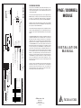
CONNECTIONS
A
A,B or C
CONTACT CLOSURE
The operation of the PDM may be customized in many ways. The
following sections describe some of the most common. Please
contact Technical Support if you have additional questions about
customizing the PDM.
The doorbell chime trigger inputs may be used to simply mute the
MRX/PX-600 (if, for example, you want to be able to hear the existing
doorbell). To accomplish this, simply remove R20. This prevents
the doorbell chimes from being routed to the PDM’s AUDIO OUT.
PAGE / DOORBELL
MODULE
Similarly, removing R19 will prevent the signals at both AUDIO
INPUTS from being routed to the AUDIO OUT, while still allowing
these signals to mute the MRX/PX-600.
AUDIOACCESS
Door 1
Door 2
PAGE / DOORBELL MODULE
1
2
3
4
To Door Input
The doorbell chime may be triggered by a TTL compatible (+5 VDC)
signal. Configure the trigger type for a 10-24 VAC input and connect
terminal 1 (or 3) to the TTL signal and terminal 2 (or 4) to the signal’s
return.
B
Audio In 1
Audio In 2
Audio Out
12 VDC
Mute Out
DOORBELL
10–24VAC
• Microphone Paging
• Paging Output From Phone System
• Other Audio Source
Mono 1/8" Phone Jacks
*
The PDM AUDIO INPUTS were designed to work with an audio input
signal with a maximum level of 1 volt peak to peak. If you are using
them with other audio signals, the gain may be too high (audio
clipping will occur) or too low (the level of the doorbell chime and the
page audio are too dissimilar). As supplied by the factory, the gain
on the AUDIO INPUTS is 10, and is set by the two 10k resistors at
R13 and R14, and the 100k resistor at R15. If, for example, you wish
to decrease the gain only on AUDIO INPUT 1, simply increase the
value of R13. Increasing the value to 100k will give unity gain. If you
wish to increase the gain, decrease the value of R13. You should
be aware that this resistor also sets the input impedance for AUDIO
INPUT 1, so be careful how much you decrease the value. No lower
than 2k is a good rule of thumb. If you wish to change the gain only
on AUDIO INPUT 2, change R14 instead. If you wish to change the
gain on both inputs by the same amount, change R15. Here,
increasing R15 will increase the gain, and decreasing R15 will
decrease the gain.
INSTALLATION
MANUAL
The pitch of the doorbell chimes may be changed by replacing the
82k resistors at R11 (Door 1) and R12 (Door 2). Decreasing the
resistance increases the pitch and vice versa. If you try this, be
aware that the pitch is very sensitive to the value of this resistor.
Small changes will produce dramatic results.
1
2
3
4
5
6
7
H 1
H 3
/
/
CONTACT
CLOSURE
1
2
H 2
H 4
10 – 24
VAC
JUMPER S
1
2
3
4
5
6
7
1
2
JUMPER S
PANASONIC
To Door Input
Must Be Polarized Correctly
Electronic Key
Telephone System
INTERNAL JUMPER SETTINGS
DOOR 1
DOOR 2
DIO INPUT
ITY
1 or 3
2
4
Std Phone Jack
DOOR 1
Red
Green
PANASONIC DOORPHONE
To MRX/PX-600 "Audio Page Input"
C
Panasonic Easa-Phone
Model # KX – T30865 Doorphone
To MRX/PX-600 "Mute" *
12V DC Power Supply *
* Cables and Adapter Supplied
To Door Input
123
123
123
CUSTOMIZING THE PDM
Audioaccess © 1996
Hayward, CA
Made in USA
A Harman International Company
505-00027-00
AUDIOACCESS
PAGE / DOORBELL MODULE
INTRODUCTION
The Page/Doorbell Module (PDM) is used to generate doorbell
chimes and/or route page audio through selected zones in an MRX/
PX-600 installation. The PDM generates two independently triggered doorbell chimes and has two page audio inputs. The doorbell
chimes and the page audio input signals are routed to the MRX/
PX-600 AUDIO PAGE INPUT. When the PDM detects presence of
either a doorbell chime or page audio, it generates a mute signal. It
then feeds this signal to the MRX/PX-600 MUTE INPUT. Under
software control in the MRX/PX-600, this signal causes the MRX/PX600 to switch to the AUDIO PAGE INPUT in selected zones and to
output the AUDIO PAGE INPUT signal at pre-defined volumes.
Each zone in the MRX/PX-600 may be programmed to allow the
AUDIO PAGE INPUT signal to play when the zone is off, and/or when
the zone is on, or not at all. Additionally, the volume of the signal is
programmable for each zone independent of the maximum, current,
or turn on volume.
CONNECTING THE PDM
Power to the PDM is supplied by a 12 VDC, 300 mA adapter which
is provided with the unit. Plug the 3.5 mm plug of this adapter into
the jack marked “12 VDC”. This adapter must be plugged into an
unswitched outlet.
Connect the AUDIO OUT of the PDM to the AUDIO PAGE INPUT of
the MRX using one of the two 6 foot, 3.5 mm plug to 3.5 mm plug
cables provided with the unit. Connect the AUDIO OUT of the PDM
to the AUDIO PAGE INPUT of the PX-600 using the 3.5 mm plug to
RCA cable provided with the unit.
Connect the MUTE OUT of the PDM to the MUTE INPUT of the MRX/
PX-600 using the other 6 foot 3.5 mm plug to 3.5 mm plug cable.
Connect the doorbell chime trigger inputs at the removable screw
terminal block. The trigger inputs for DOOR 1 are terminals 1 and 2,
and the trigger inputs for DOOR 2 are terminals 3 and 4. The terminal
block will accept 18-22 AWG wire.
Note: If the Panasonic Doorphone is the trigger source, it must be
connected exactly as shown in the diagram. If the connections are
reversed or if they are disconnected, the PDM doorbell chime will
sound continuously. If the power to the Panasonic phone system is
interrupted while the PDM and MRX/PX-600 remain powered, the
doorbell chime will also sound continuously.
PX-600 PAGING SETUP
PAGING
The PDM has two audio inputs designed to work with audio signals
with a maximum amplitude of approximately 1 volt peak to peak. The
signals applied to the two inputs are combined in the PDM and
routed to the AUDIO OUT of the PDM.
The PDM monitors the presence of the audio input signals and
generates a mute signal when the audio signal level exceeds a
predetermined threshold. This threshold is user-adjustable by
setting a trim pot (R42) located inside the PDM. The minimum
threshold is at the full counterclockwise rotation and the maximum
threshold is at the full clockwise rotation. The PDM is shipped from
the factory with the threshold set in the middle of its range, which
should be acceptable for most applications.
Once the mute signal is generated, it will continue for 3 to 4 seconds
after the audio signal falls below the detector threshold. This is
intended to keep the MRX/PX-600 in the page mode during brief
pauses in the page audio.
MRX PAGING SETUP
The PDM must be used with MRXs equipped with V2.xx software or
greater. Below is an excerpt from the V2.xx Software Guide for the
Paging Setup. All selections and changes are made by pressing the
TUNE UP/DOWN buttons, which in turn move a highlight bar up and
down or change an alphanumeric value. Press STORE to confirm
the selection.
❖
Enter Programming Mode by pressing PRESET 1 and MUTE.
❖
Select PAGING SETUP. Press STORE.
❖
PAGE IF ZONE OFF? Select Zone Number. Press STORE.
Programming Instructions:
❖
Enter programming mode by pressing PGM on the programmer.
❖
Select PAGING SETUP. Press ENTER.
❖
The first screen will say PAGE IF ZONE OFF. All zones will be
listed with the default choice of YES. If you wish to set up any
zone so that it will not receive paging/doorchime signals when
off, select the zone to change and press ENTER.
❖
Use the ▲ ▼ buttons to select NO. Press ENTER.
❖
Repeat for any zone you wish to exclude from receiving paging/
doorchime signals when off.
❖
Press ENTER while the highlighter is on —EXIT—.
❖
The next screen will say, PAGE IF ZONE ON. The default
choice is YES for each zone. If you wish to set up any zone so
that it will not receive paging or doorchimes when on, select the
zone to change and press ENTER.
❖
Use the ▲ ▼ buttons to select NO. Press ENTER.
❖
Repeat for any zone you wish to exclude from paging/doorchime
signals when on.
❖
Press ENTER while the highlighter is on —EXIT—.
❖
The next screen will say PAGE ZONE VOLUME. Set the volume
at which the page or doorchime is to be played. This volume is
independent of the volume at which the zone may be operating.
The default volume setting is 16.
❖
Select zone number. Press ENTER.
❖
Select desired volume. Press ENTER.
❖
Repeat for each zone and then press ENTER while the highlighter
is on — EXIT—.
❖
Select YES or NO. Press STORE.
Connect the Page audio signals to the PDM via the 3.5 mm mono
jacks labeled AUDIO IN 1 and AUDIO IN 2.
CAVEATS
❖
Repeat for each zone until your selections are complete. Then
highlight -EXIT- and Press STORE.
DOORBELL CHIMES
❖
PAGE IF ZONE ON? Select Zone Number. Press STORE.
❖
Select YES or NO. Press STORE.
Because there is only one AUDIO PAGE INPUT and one MUTE
INPUT on the MRX/PX-600, it is not possible to distinguish between
the two doorbell chimes, or between the two PDM AUDIO INPUTS,
or between the doorbell chimes and the page audio. This means that
you can’t split the doorbell chimes and/or the page audio among the
zones.
❖
Repeat for each zone until your selections are complete, then
highlight -EXIT- and press STORE.
❖
PAGE ZONE VOLUME - Select the volume the page or
doorchime will play regardless of what the correct volume level
of the zone is. Be advised that the output of the PDM is
somewhat higher than other sources, and you may want to
select conservative levels. The default as of V2.3 = 16.
The PDM generates two independently triggered doorbell chimes.
Each doorbell chime can be configured for 1, 2, or 3 chimes. Header
#3 is used to configure door 1 and header #4 is used to configure
door 2. See Connections Diagram for jumper settings. The two
doorbell chimes may each be triggered in one of three ways: by
contact closure, by a 10-24V AC/DC voltage, or by the output of a
Panasonic Doorphone (Model KX-T30865). There are two headers
(H1 and H2) inside the PDM, programmed with shunt jumpers, that
determine to which trigger type each doorbell chime of the PDM
responds. The accompanying diagram shows the shunt jumper
locations and the trigger connections for each trigger type. The PDM
is shipped from the factory with both doors configured to respond to
contact closures. Door 1 is configured for 2 chimes and door 2 for
3 chimes.
When the PDM is used with the Panasonic Doorphone, failure of the
connection to the Doorphone or loss of power to the phone system
will cause the PDM to chime continuously. This is because the
signals generated by the Panasonic Doorphone in response to
pressing the Doorphone’s button are the same as the signals that are
present with a loss of connection or power. If you are using the PDM
with a Panasonic Doorphone as a trigger, please keep this in mind
when designing the installation.
If you wish to use the PDM with the door box of a telephone system
other than Panasonic, please contact our Technical Support Department for further information.