1
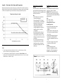
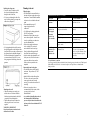
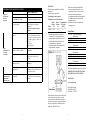
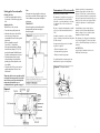
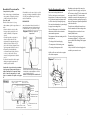
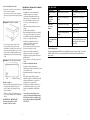
Thermostatic
Garantía limitada de 5 años del Powerstream Pro
APPLIED ENERGY PRODUCTS, A TRAVÉS DE SU
DISTRIBUIDOR EN LOS EE.UU., BOSCH WATER
HEATING (en lo sucesivo denominado BBT)
garantiza este calentador de agua instalado en la ubicación
original contra defectos en los materiales y en la fabricación
durante el período de tiempo indicado a continuación.
b) El calentador de agua no se ha instalado en conformidad
con la normativa aplicable de fontanería y/o normativa de
vivienda y/o reglamentos, o
Período de garantía
1. Intercambiador térmico/Elemento: si existen pérdidas o
fallos en el intercambiador térmico en los cinco (5) años
a partir de la fecha de instalación original del calentador
de agua y que estén ocasionados por un defecto en el
material o la fabricación, BBT proporcionará al
propietario un nuevo calentador igual al modelo actual.
d) No existe un suministro continuo de agua potable
en el calentador de agua.
2. Otros componentes que no sean el intercambiador
térmico/Elemento: si otro componente (que no sea el
intercambiador térmico) presenta defectos en el material
o la fabricación antes de un (1) año a partir de la fecha
de instalación original del calentador de agua, BBT
sustituirá los componentes defectuosos.
3. Verificación de la fecha de instalación original: cuando
el propietario no pueda verificar o documentar la fecha
de instalación original, el período de garantía dará
comienzo en la fecha de fabricación marcada en la
etiqueta fijada al calentador de agua.
Exclusiones
1. ESTA GARANTÍA LIMITADA SERÁ LA
GARANTÍA EXCLUSIVA DEL FABRICANTE Y
EXCLUYE TODAS LAS DEMÁS GARANTÍAS
EXPRESAS O TÁCITAS (POR ESCRITO O DE
PALABRA), INCLUYENDO, ENTRE OTRAS, LAS
GARANTÍAS DE COMERCIABILIDAD O
IDONEIDAD PARA UN FIN DETERMINADO.
c) El calentador de agua no se ha instalado en
conformidad con las instrucciones impresas del
fabricante, o
5. El PROPIETARIO, y no el fabricante o su representante,
se responsabilizará y pagará todos los gastos de mano de
obra u otros gastos incurridos en el desmontaje y/o
reparación del equipo, o gastos incurridos por el
propietario a fin de reparar el equipo.
ALGUNOS ESTADOS NO PERMITEN QUE SE
ESTABLEZCAN EXCLUSIONES O LIMITACIONES DE
DAÑOS FORTUITOS O RESULTANTES, POR LO QUE
ES POSIBLE QUE LA ANTEDICHA LIMITACIÓN NO
LE SEA DE APLICACIÓN A USTED. ESTA GARANTÍA
LE CONCEDE DERECHOS JURÍDICOS ESPECÍFICOS, Y
ES POSIBLE QUE USTED TENGA OTROS DERECHOS.
IMPORTANTE - EL PROPIETARIO DEBE
GUARDAR ESTE CERTIFICADO
Nota: La instalación de un calentador de agua se debe
realizar de modo que, en caso de pérdidas, el caudal de agua
resultante no produzca daños donde se instale.
2. El fabricante no se responsabilizará de los daños
imprevistos, resultantes, especiales o contingentes, ni de
los gastos que surjan directa o indirectamente de los
defectos en el calentador de agua o de su uso.
OBTENCIÓN DE ASISTENCIA O REALIZACIÓN DE
UNA RECLAMACIÓN POR PARTE DEL
PROPIETARIO
1. El propietario debe ponerse en contacto con el
establecimiento donde adquirió el calentador de agua
cubierto por la garantía, o
2. El propietario debe enviar la reclamación de garantía
directamente a BBT a la dirección indicada a
continuación, y ellos gestionarán la tramitación de la
reclamación.
3. El fabricante no se responsabilizará de los daños
producidos por el agua que surjan directa o
indirectamente de los defectos en los componentes del
calentador de agua o de su uso.
3. Cuando se efectúen consultas o solicitudes de servicio,
asegúrese de incluir el número de modelo del calentador,
la fecha de fabricación, la fecha de instalación, el nombre
del establecimiento de compra y la potencia y el voltaje.
4. El fabricante está exento de responsabilidad bajo esta
garantía si:
4. Cuando envíe el calentador de agua o los componentes,
deben estar etiquetados e identificados individualmente
con el número de Autorización de Artículo Devuelto
emitido por BBT, y se debe enviar con portes pagados a
BBT a la siguiente dirección:
a) El calentador de agua o cualquiera de sus componentes
se ha sometido a una mala utilización, alteración,
negligencia, accidente, congelación o
Bosch Water Heating
340 Mad River Park
Waitsfield, VT 05673
800-798-8161
www.boschpro.com
559 2343 09A
MODEL
RP12PT
240V
For Service & Installation contact:
BBT NORTH AMERICA
Bosch Group
340 Mad River Park, Waitsfield, VT 05673 - 800-798-8161
www.boschpro.com
IMPORTANT : This booklet should be
given to the customer after
installation and demonstration.
12.14.05
© 2005 Bosch Water Heating
Waitsfield, VT Todos los derechos reservados
1
Important Safety Instructions
When using this electrical equipment, basic safety precautions should always be followed,
including the following:
1. Read and follow all instructions.
2. This appliance must be grounded.
3. Disconnect this product from the electrical supply before cleaning, servicing or removing the
cover.
4. lo reduce the risk of injury, close supervision is necessary when the product is used near
children or elderly persons.
5. Warning: Do not install the heater in a location where it may be subject to freezing.
6. Warning: Do not install a check valve or any other types of back flow preventer within six
feet of the cold water inlet.
7. The electrical insulation must conform to current National Electrical Codes.
8. Warning: Do not switch the heater on if you suspect that it may be frozen. Wait until you are
sure that it has completely thawed cut.
9. The Powerstream Pro is designed to heat potable cold water for domestic purposes.
Contact Bosch Water Heating before specifying or installing the appliance in any other
application.
10. Additional Canadian Safety Instructions
a) A green terminal (or wire connector marked "G", "GR", "GROUND", or
"GROUNDING") is provided within the control box. To reduce the risk of electric shock,
connect this terminal or connector to the grounding terminal of the electric service of
supply panel with a continuous copper wire in accordance with the Canadian Electrical
Code, Part 1.
b) This product shall be protected by a Class A ground fault circuit interrupter.
Contents
Using the Powerstream Pro
Installing the Powerstream Pro
Spare parts
Starting up the Powerstream Pro
How the Powerstream Pro works
Trouble shooting
Warranty
Cover
3
3
5
6
7
8
Back
Save these instructions
Keep this guide in a safe place once your Powerstream Pro unit has been installed. You may need
to refer to it for general instructions or future maintenance.
2
Apéndice
Guía de ajuste de la relación caudal / temperatura:
El siguiente gráfico indica las temperaturas del agua que puede alcanzar el Powerstream Pro termostático a
diferentes caudales. El gráfico muestra las temperaturas máxima y mínima que pueden obtener la unidad
de 12kW con la temperatura del agua de entrada ajustada a una temperatura ambiente promedio.
Temperatura del agua de entrada
Temperatura (ºF)
Ajuste máximo
Ajuste mínimo
Caudal (galones por minuto)
Using the Powerstream Pro
Installing the Powerstream Pro
Warning
Do not use the unit if you think it may be frozen,
as this could result in serious damage to the unit.
Wait until you are sure-it has completely thawed
out before you switch it on.
Warning
Do not install the Powerstream Pro in a room:
where there is a chance of freezing.
IMPORTANT - Read entire instructions
Check the pressure of the main water supply.
To operate correctly the unit needs the following
running pressures:Sink
Min: 20psi (1.4 bar)
Max: 150psi (10.3 bar)
Securing the unit to the wall
Deciding the position
• If being used in a public place, position
the unit out of reach to discourage
vandalism.
• Mount the unit onto a flat section of wall,
well away from any potential splashes of
water or spray.
• Position the unit lengthways (diagram 1.)
Remember to keep the length of hot
water pipe to a minimum in order to save
energy.
• If the unit is to supply a sink, you can It
it either above or below the sink.
Sink
• Check that the power is switched on
at the circuit breaker panel.
• Turn on the hot tap FULLY If you do
not turn the tap full on, you will find that
the temperature of the water may vary
The hot water can be adjusted by
altering the temperature dial and
correctly setting the flow rate. Refer to
appendix on page 10 - correct flow
vs. temperature,
• If the unit has been used recently, run
the water through for a few seconds to
let the temperature settle down. You may
initially get a short burst of very hot water
from the unit,
• It a second tap connected to the unit
is also turned on, the hot water will be
shared between the two, therefore the
flow and/or the temperature of the water
will decrease.
Warning
Unit must be mounted as shown
'Lengthways' with plumbing connection
pointing down. Under no circumstances
should the unit be mounted differently.
NOTA:
1.
Ya que la temperatura del agua varía durante todo el años, es posible que haya que realizar
ajustes en el orificio de ajuste de temperatura y/o en el caudal.
2.
Se recomienda ajustar el caudal del calentador a la temperatura de Invierno Máximo (véase el
gráfico anterior). El calentador mantendrá la temperatura ajustada en los meses de verano y reducirá
automáticamente el consumo de energía.
10
3
Deciding the wiring route
• You have a choice of whether to feed
the electric cable through the side or
through the back of the unit,
• If it is gong to be through the side of the
unit, cut out the plastic lug to expose the
rubber sleeve (diagram 2.)
Plumbing in the unit
Fitting the pipes
• The unit should be connected directly to
the main cold water supply and not to preheated water. The unit should be installed
with service valves on both the inlet and
outlet.
• We recommend that you use ½"
copper or high pressure flex
connections.
• Use Teflon tape for sealing pipe threads.
Do NOT use pipe dope.
• Remember to keep the hot water pipe
runs as short as possible. In some cases
it may be worth fitting a second unit to
serve an additional fixture.
• If the unit is to supply more than one
sink, a similarly flow restricted
• If it is going through the back of the unit, cut
aerator should be used at each tap.
through the grommet on the backplate with a
If not, the highest flowing outlet will
sharp knife. Make sure that you do not remove
take all the water under dual usage.
the grommet from the backplate (diagram 3.)
Feed the cable through the grommet before
• After the unit has been plumbed in, and
you mount the unit to the wall. If you are
before you wire it, flush it with water to
using an approved cable fitting, remove the
remove any debris or loose particles.
grommet.
Failure to do so may make the unit
inoperable.
Connecting the unit to the pipes
• The inlet and outlet are clearly marked
on the unit. They each have a ½" NPT
connector.
• Install a ball valve in the cold water line.
This valve can be used to turn off the
water supply to the unit if it needs
servicing, or to reduce the water flow if it
is too high.
• If the unit is to supply a sink, we
recommend that you use aerators, which
you can get from your local
distributor/dealer.
Mounting on the wall
• Undo the retaining screws on the cover
and take the cover of the unit. Hold the
backdate in position against the wall while
you mark the four mounting holes.
• Drill the holes and secure the unit to the
wall using the four no. 8 wood screws
supplied
WARNING - IMPORTANT
Do not install a non-return check valve
within 6 feet of the inlet.
INFORMACIÓN PARA EL USUARIO
SÍNTOMA
CAUSA
ACCIÓN CORRECTIVA
Caudal de agua bajo o El suministro de agua está apagado.
inexistente.
Únicamente
agua fría – luz
neón apagada
El caudal no es lo suficientemente
alto para activar la unidad.
Abra totalmente la válvula de servicio
de entrada.
Únicamente
agua fría – luz
neón encendida
El caudal de agua es demasiado
alto
El caudal de agua es correcto
Ajuste el caudal.
Disminución de la temperatura del
agua de entrada.
Ajuste el caudal.
El grifo de agua caliente no está
totalmente abierto
Ajuste la válvula de cierre/esférica para
que el agua esté a la temperatura
correcta con el grifo totalmente abierto.
Abra siempre totalmente el grifo de
agua caliente.
Caudal de agua
demasiado bajo o
temperatura
demasiado alta
Ajuste el control de temperatura en la
parte frontal de la tapa.
Si el problema no se soluciona
La persona que instaló inicialmente la unidad es la más adecuada para proporcionarle ayuda. También puede
llamar a BBT en el 800-798-8161 o visitar www.boschpro.com. Tenga a mano este manual cuando
llame por teléfono.
• As a condition of installing this product in
the Commonwealth of Massachusetts a
pressure relief valve must be installed on the
cold water side by a licensed plumber. MGL 42
Section 19.
4
Abra totalmente el suministro principal
en la válvula de cierre.
9
INFORMACIÓN PARA EL INSTALADOR
SÍNTOMA
CAUSA
ACCIÓN CORRECTIVA
Agua fría
únicamente –
luz neón
apagada.
No hay electricidad
Compruebe el suministro eléctrico.
El suministro de agua está conectado
en la SALIDA de la unidad.
Vuelva a conectar el suministro de agua
en la entrada de la unidad (marca azul).
Se ha disparado un disyuntor térmico
de alta temperatura
Reajuste el disyuntor: abra la unidad y
presione el botón en el disyuntor
(diagrama 7).
Antes debe averiguar la causa del
problema.
Agua
demasiado fría
–luz neón
encendida.
Caudal de agua
demasiado bajo o
temperatura
demasiado alta.
El conmutador de caudal no
funciona.
Desconecte el suministro eléctrico y
observe si el conmutador de caudal se
activa cuando se enciende el agua. En
caso contrario, póngase en contacto con
BBT en el
800-798-8161
www.boschpro.com
El caudal de agua es demasiado alto
para que lo controle la unidad
Ajuste el caudal de agua al valor
recomendado.
Un elemento no funciona.
Apague el suministro eléctrico y
compruebe la resistencia de los
elementos.
Disminución del voltaje de
suministro eléctrico.
Compruebe el voltaje de suministro en
el calentador.
El ajuste de temperatura es
demasiado bajo.
Asegúrese de que el control de
temperatura esté en la posición correcta
para el caudal de agua.
Existen restricciones en las tuberías
de fontanería.
Compruebe la fontanería. Utilice sólo
cinta de teflón para sellar las juntas de
las tuberías.
WARNING
The unit must be installed by a qualified
electrician.
The unit must be grounded.
• Make sure that all the terminal block
screws are tightened securely. Loose
connections can cause wires to neat up.
• Make sure that the ground wire is
wrapped around its terminal stud and into
the saddle washer. The nut should be
tightened securely.
• Attach the front cover and tighten the
retaining screws.
Connecting the unit to power.
Making the electrical connections
Rated
Rated
Recommended
Voltage Current
Wire Size
Model
(V)
(A)
(AWG)
RP12PT
240
50
6
Spare Parts
• Strip back the insulation on the power
wires about 3/8". Any insulation on the
ground should be stripped back about 3/4"
• Feed the cable through the side or rear
entry grommets, as appropriate.
• Connect the cables to the terminal block
and ground stud. (diagram 4.)
93793749 12 kW Heat Exchanger
(Thermostatic)
93793701 Backplate
93793703 Terminal Block
93793812 Front Cover
(Thermostatic)
93793765 Thermal Cut-cut
93793751 Wiring Assembly
(Thermostatic)
937937C9 Cable Clamps & Rubber Boot
93793752 Cover Retaining Screws
93793753 12 kW Printed Circuit Board
(Thermostatic)
93793754 Nameplate
93793755 Brass Inlet Assembly
For further information ask your local dealer:
FOR SERVICE AND INSTALLATION
QUESTIONS CALL TOLL FREE:
800-798-8161
www.boschpro.com
Bosch Water Heating
340 Mad River Park,
Waitsfield. VT 05673.
When the Powerstream Pro is not within sight
of the electrical circuit breakers, a circuit
breaker lockout or additional local means of
disconnection for ail non grounded conductors
must be provided that is within sight of the
appliance. (REF NEC 422.31)
8
5
Note:
If the unit is servicing a single lever faucet you
may need to restrict the cold water supply to the
faucet to balance water pressure and improve
performance.
Starting up the Powerstream Pro
Checking for leaks
• Lot the water run through the unit for a
few seconds. Check that no pipe joints
leak.
Adjusting the flow
Turn the service valves on, then • Turn on the hot tap fully at the sink
• Adjust the outlet service valve till the
water cones out of the tap at the
recommended flow rate for the required
temperature.
Refer to Appendix on page 10 :
Correct flow vs. Temperature.
If the required temperature is different
from the factory setting 113°F (45°C),
turn the Adjustment Spindle (Diagram
5) until the outlet temperature is correct.
• Check that the unit works correctly
when the sink tap is closed and then
opened again; if not adjust the service
valve slightly.
• The outlet shut off valve can be used to
regulate temperature or flow of water
from the unit.
IMPORTANT
Before leaving the site, the installer should
demonstrate the unit to the user and give
him/her this guide.
Según la región del país, la temperatura del
suministro de agua puede variar entre 4ºC en
invierno a 21ºC en verano, con una media de unos
10ºC. Las condiciones climáticas extremas pueden
hacer que la temperatura de entrada sobrepase estos
límites, por lo que será necesario ajustar el orificio
de ajuste de temperatura o el caudal del agua de
entrada.
Funcionamiento del Powerstream Pro
El agua entra por el tubo de entrada.
El conmutador de caudal detecta el agua que ha
pasado por la unidad. Si detecta más del nivel
preajustado, se activan las unidades que calientan
los elementos. Esto se indica con la luz neón
encendida.
La unidad incluye un cierre térmico bipolar
montado en el tubo del intercambiador térmico.
El agua se calienta de forma instantánea a medida
que pasa por el tubo intercambiador térmico de
cobre.
Cuando se dispara el cierre, se deberá reajustar
manualmente dentro de la unidad.
La unidad es termostática, es decir, enciende y
apaga los elementos para mantener una temperatura Este disyuntor sólo se disparará en circunstancias
de salida constante.
excepcionales (diagrama 7). Llame al personal de
servicio o a Bosch Water heating si esto sucede con
La temperatura del agua que sale de la unidad
frecuencia.
depende de lo siguiente:
ADVERTENCIA Apague siempre el suministro eléctrico en la
unidad antes de retirar la tapa.
• El voltaje del suministro eléctrico.
• La temperatura del agua que entra.
• El ajuste del control de temperatura.
Un caudal ajustado incorrectamente puede tener
también un efecto negativo en la temperatura.
Diagrama 7: Disyuntor térmico
When using the hot water open the tap fully
so that the water temperature is always the
same. If hotter water is desired adjust the
temperature dial and flow rate as
recommended in the Appendix on page 10.
6
7
Encendido del Powerstream Pro
Comprobación de pérdidas
• Deje circular el agua por la unidad durante
unos segundos. Compruebe que no haya
pérdidas en las juntas de las tuberías.
Ajuste del caudal
Abra las válvulas de servicio, y luego
• Abra totalmente el grifo de agua caliente en el
lavabo
• Ajuste la válvula de servicio de salida
hasta que salga el agua del grifo con el
caudal recomendado y la temperatura
deseada.
Consulte el Apéndice en la página 10:
Ajuste el caudal en relación con la
temperatura. Si la temperatura deseada es
diferente del ajuste de fábrica de 45°C,
gire el orificio de ajuste (diagrama 5) hasta
que la temperatura de salida sea correcta.
• Compruebe que la unidad funcione
correctamente cuando el grifo del lavabo
se cierra y se abre de nuevo. En caso
contrario, ajuste ligeramente la válvula de
servicio
• La válvula de retención de salida se puede
utilizar para regular la temperatura o el
caudal de agua de la unidad.
How the Powerstream Pro works
Si la unidad da servicio a un solo grifo, es posible
que tenga que restringir el suministro de agua fría
en el grifo para equilibrar la presión de agua y
mejorar el rendimiento.
Water comes in through the inlet tube.
IMPORTANTE
Antes de abandonar el lugar de instalación, el
instalador debe demostrar el funcionamiento de
la unidad al usuario y proporcionarle esta guía.
Diagrama 5: Orificio de ajuste de
temperatura
Depending on the region of the country, the
temperature of the water supply can vary from
40°F in winter to about 70°F in the summer, with
an average of about 50°F. Extreme weather
conditions can cause the inlet temperature to go
outside these boundaries, making it necessary to
adjust the Temperature Adjustment Spindle and /
or the inlet water flow.
The flow switch senses water has passed
through the unit. If it detects more than the preset level, the units heating the elements switch
on. This is shown by the neon light glowing.
The water is heated instantly as it passes through
the copper heat exchanger tube.
The unit has one double pole thermal cut out
which is mounted on the heat exchanger tube.
The unit is Thermostatic i.e. it will switch the
elements on and off in order to maintain a
constant outlet temperature.
When tripped the cut out needs to be reset
manually inside the unit.
The cut-out will trip only in exceptional
circumstances (Diagram 7.) Call your service
person or Bosch Water Heating if this happens
frequently.
The temperature of the water conning out of the
unit depends on:• The voltage of the electrical supply,
• The temperature of the incoming water.
WARNING Always switch off the electrical supply to the
unit before you remove the cover.
• The setting of the temperature dial.
A badly set flow rate can also have a negative
effect on the temperature.
Cuando utilice el agua caliente, abra totalmente
el grifo para que la temperatura del agua sea
siempre la misma. Si desea agua más caliente,
ajuste el control de temperatura y el caudal
según se recomienda en el Apéndice en la página
10.
Diagrama 6:
Vista interior
Nota:
Extraiga la placa de identificación en la
dirección de la flecha A. Ajuste la temperatura
introduciendo un destornillador en el orificio,
según lo indica la flecha B.
Vuelva a colocar la placa de identificación .
Orificio de Tubo intercambiador Placa de circuitos
montaje térmico
impresos de control
Elementos
calefactores
Bloque de
terminales
Entrada posterior del cable
Tornillo de montaje
de la tapa
Clavija de toma de tierra
Abrazadera de cable
Salida
Entrada
Disyuntor térmico de alta
temperatura (reajuste manual)
6
Entrada lateral del cable
Luz neón
7
FOR THE INSTALLER
SYMPTOM
Cold water
only -neon
light off.
ADVERTENCIA
CAUSE
Electricity not on
WHAT TO DO
Check electrical supply.
The water supply is connected to
the OUTLET of the unit.
Reconnect the water supply to the
INLET (marked in blue)
The high temperature thermal cut
out has tripped
Reset it by opening the unit and
pushing the button on the cutout
(diagram 7).
Before you do this you must find
the cause of the problem.
Turn off the power and observe if the
flow switch activates when the water
is turned on. If not contact BBT
800-798-8161
www.boschpro.com
Adjust water flow to
recommended flow rate.
The flow switch is not
working.
Water too
cold -neon
light on.
Water flow too
low, or
temperature too
high.
Water flow too high for unit to
control
One element is not working.
Switch off the electricity and check
the resistance of the elements.
The power supply voltage has
dropped.
Check the supply voltage to the
heater.
Temperature is turned too low.
Ensure that the temperature dial is
in the correct position for the flow
of water.
There are restrictions in the
plumbing.
Check the plumbing. Only use
Teflon tape for sealing pipe joints.
• Asegúrese de que los tornillos de los bloques de
terminales están firmemente apretados. Las
conexiones sueltas pueden provocar el
calentamiento de los cables.
• Asegúrese de que el cable de toma de tierra está
enrollado en la clavija del terminal y en la
arandela de asiento. La tuerca debe apretarse
firmemente.
• Coloque la cubierta delantera y apriete los
tornillos de fijación.
La unidad debe ser instalada por un electricista
cualificado.
Este equipo debe conectarse a una toma de tierra.
Conexión de la unidad al suministro eléctrico.
Realización de las conexiones eléctricas
Voltaje de
régimen
Modelo
(V)
RP12PT 240
Corriente de
Tamaño de
régimen
cable recomendado
(A)
(AWG)
50
6
Piezas de recambio
• Pele el aislamiento de los cables de alimentación,
aproximadamente 1 cm. Pele el aislamiento del
cable de toma de tierra, aproximadamente 2 cm.
• Pase el cable por el lateral o los ojales
posteriores, según corresponda.
• Conecte los cables al bloque de terminales y a la
clavija de toma de tierra (diagrama 4).
93793749 Intercambiador térmico
(termostático) 12 kW
93793701 Placa posterior
93793703 Bloque de terminales
93793812 Tapa frontal
(termostática)
Diagrama 4: Conexiones de cables
93793765 Disyuntor térmico
93793751 Unidad de conexiones
(termostática)
937937C9 Abrazaderas de cables y funda de
goma
93793752 Tornillos de sujeción de la tapa
93793753 Placa de circuitos impresos de 12 kW
(termostática)
93793754 Placa de identificación
93793755 Unidad de entrada de bronce
Para obtener más información, póngase en contacto
con su distribuidor:
Toma
de
tierra
SI TIENE ALGUNA PREGUNTA SOBRE
MANTENIMIENTO O INSTALACIÓN,
LLAME AL TELÉFONO
800-798-8161
Funda de goma
www.boschpro.com
Cuando el Powerstream Pro se instale fuera de la
vista de interruptores eléctricos, se debe suministrar
un cierre eléctrico u otra forma de desconexión para
todos los conductores sin toma de tierra, a la vista
del equipo. (Ref NEC 422.31.)
8
Bosch Water Heating
340 Mad River Park,
Waitsfield. VT 05673.
5
Selección del trazado de los cables
Instalación de fontanería de la unidad
• Puede pasar el cable eléctrico por el lateral o por
Montaje de las tuberías
la parte posterior de la unidad.
• La unidad debe conectarse directamente al
• Si se va a pasar por el lateral, corte el saliente de
suministro de agua fría y no al de agua
plástico para exponer la funda de goma (diagrama
precalentada. La unidad debe instalarse con
2).
válvulas de servicio en la entrada y la salida
• Se recomienda utilizar conexiones de cobre
Diagrama 2: Lateral de la unidad
de 1,3 cm o conexiones flexibles de alta
presión.
• Utilice cinta de teflón para sellar las roscas de las
tuberías.
NO utilice aditivos para tuberías.
• Recuerde mantener la tubería de agua caliente lo
más corta posible. En algunos casos, puede ser
recomendable montar una segunda unidad para
dar servicio a un dispositivo adicional.
• Si la unidad va a suministrar a más de un
sumidero, se debe utilizar un aireador de
• Si se va a pasar por la parte posterior, corte a
caudal restringido en cada grifo.
través del ojal de la placa posterior con un
En caso contrario, la salida de mayor caudal
cuchillo afilado. Asegúrese de no extraer el ojal
llevará toda el agua bajo uso doble.
de la placa posterior (diagrama 3). Pase el cable
• Cuando se haya realizado la instalación de
por el ojal antes de montar la unidad en la pared.
fontanería y antes de que conecte la unidad,
Si utiliza una pieza de cable autorizada, extraiga
enjuáguela con agua para quitar la suciedad o las
el ojal.
partículas sueltas.
En caso contrario, es posible que no funcione la
Diagrama 3: Parte trasera de la unidad
unidad.
Ojal
FOR THE USER
SYMPTOM
Little or no water
flows.
CAUSE
The water supply is turned off.
WHAT TO DO
Turn on the main supply fully at the
stop valve.
Cold water
only -neon
light off.
Cold water
only -neon
light on.
The flow is not high enough to
activate.
Open the inlet service valve fully.
The water flow rate is too high.
Adjust the flow rate.
The flow rate is correct
Adjust the temperature dial on the
front of the cover.
Adjust the flow rate.
The inlet water temperature has
dropped.
Water flow rate too The hot tap is not fully open
low, or temperature
too high.
If the problem persists
The person who initially installed the unit is probably the best one to contact for help. You can also
call BBT at 800-798-8161 or visit www.protankless.com/tech. Please have this guide with you
when you call.
Conexión de la unidad a las tuberías
• La entrada y la salida están claramente
identificadas en la unidad. Cada una dispone de un
conector NPT de 1,3 cm.
• Instale una válvula esférica en la tubería de agua
fría.
Esta válvula se puede utilizar para cerrar el
suministro de agua fría en la unidad si hace falta
realizar un mantenimiento, o para reducir el
caudal de agua si es demasiado alto.
• Si la unidad va a suministrar a un sumidero, se
recomienda utilizar aireadores, que se pueden
adquirir en su distribuidor o establecimiento
local.
Orificios de montaje
Montaje en la pared
• Suelte los tornillos de fijación situados en la tapa y
extraiga la tapa de la unidad. Sujete la placa
posterior contra la pared y marque los cuatro
orificios de montaje.
• Taladre los orificios y fije la unidad a la pared
con los cuatro tornillos de madera suministrados
del nº 8.
ADVERTENCIA - IMPORTANTE
No instale una válvula de retención
a menos de 1,8 m de la entrada.
• Como condición para la instalación de este
equipo en la Commonwealth de Massachusetts se
debe instalar una válvula de seguridad en el lado
del agua fría por un fontanero autorizado. MGL
42 Sección 19.
4
Adjust the stop/ball valve so that
water is at the right temperature with
the tap fully open. Always turn the
hot tap fully on.
9
Appendix Flow vs. Temperature Setting Guide:
Uso del Powerstream Pro
The following graph Indicates the water temperatures the Thermostatic Powerstream Pro can
achieve at different flow rates. The graph shows the maximum and minimum temperatures
achievable for the 12 kW unit with the inlet water temperature set to an average ambient
temperature.
Advertencia
No utilice esta unidad si cree que se puede
congelar, ya que se podría dañar gravemente la
unidad. Espere hasta que esté seguro de que se haya
descongelado completamente antes de encenderla.
Instalación del Powerstream Pro
Advertencia
No instale el Powerstream Pro en una habitación:
donde se pueda congelar.
IMPORTANTE – Lea las instrucciones
completas. Compruebe la presión del suministro de
agua principal. Para que el funcionamiento sea
Sumidero
correcto, la unidad requiere las presiones de
• Compruebe que está conectado el suministro
funcionamiento siguientes:
eléctrico en el panel de interruptores.
Sumidero
• Abra COMPLETAMENTE la llave de agua
Mín: 1,4 bar
caliente. Si no abre totalmente la llave,
Máx: 10,3 bar
comprobará que la temperatura del agua puede
variar. La temperatura del agua caliente se puede Instalación de la unidad en la pared
Selección de la posición
cambiar con el disco de temperatura y ajustando
correctamente el caudal. Consulte el apéndice 10
• Si la unidad se utiliza en un área pública, realice
para la relación correcta entre caudal y
su montaje de forma que no se llegue fácilmente
temperatura.
a la unidad, con el fin de impedir el vandalismo.
• Si se ha utilizado recientemente la unidad, deje
• Monte la unidad en una sección plana de la
circular el agua unos segundos para que se
pared, alejada de las posibles salpicaduras de
estabilice la temperatura. Es posible que se
agua.
produzca una descarga corta de agua muy caliente
• Coloque la unidad a lo largo (diagrama 1).
de la unidad.
Reduzca al mínimo la longitud del tubo de agua
• Si también se abre una segunda salida conectada
caliente para ahorrar energía.
a la unidad, el agua caliente será compartida entre • Si la unidad va a suministrar agua en un
las dos salidas, por lo que el caudal y/o la
sumidero, puede instalarla por encima o por
temperatura del agua disminuirá.
debajo de éste.
Advertencia
La unidad se debe montar según se ilustra
La colocación se debe efectuar ‘a lo largo’ con las
uniones de las tuberías orientadas hacia abajo. En
ningún caso se deben montar la unidad de forma
diferente.
NOTE:
1. As water temperature varies throughout the year adjustments to the Temperature
Adjustment Spindle and/or the flow rate may be required.
2. We recommend the flow rate through the heater is set to the Winter Maximum
temperature (see graph above). The heater will then maintain the set temperature in the summer
months reducing the power automatically.
Diagrama 1
Fría
Caliente
Fría
Caliente
Fría
Caliente
Vista desde la parte posterior
10
3
Instrucciones importantes de seguridad
Cuando utilice este equipo eléctrico, se deben seguir las precauciones básicas de seguridad,
incluyendo las siguientes:
1.
Lea y cumpla todas las instrucciones.
2.
Este dispositivo debe conectarse a una toma de tierra.
3.
Desconecte el equipo del suministro eléctrico antes de limpiarlo, realizar un mantenimiento o extraer
la cubierta.
4.
Para reducir el riesgo de lesiones, es necesario efectuar una supervisión cuidadosa cuando el equipo
se utiliza cerca de niños o personas mayores.
5.
Advertencia: No instale el calentador en un lugar donde se pueda congelar.
6.
Advertencia: No instale una válvula de retención ni otro tipo de limitador de caudal de retorno a
menos de 3 m de la entrada de agua fría.
7.
La instalación eléctrica debe estar en conformidad con la Normativa Eléctrica Nacional.
8.
Advertencia: No conecte el calentador si sospecha que se puede congelar. Espere hasta que esté seguro
de que se haya descongelado completamente.
9.
El Powerstream Pro está diseñado para calendar agua fría potable para uso doméstico. Póngase en
contacto con Bosch Water Heating antes de especificar o instalar el dispositivo en otra aplicación.
10. Instrucciones de seguridad adicionales para Canadá:
a) Se suministra un terminal verde (o un conector con la marca marked "G", "GR", "GROUND", o
"GROUNDING") dentro de la caja de control. Para reducir el riesgo de descargas eléctricas,
conecte este terminal o conector al terminal de toma de tierra del servicio eléctrico del panel
de suministro mediante un cable de cobre, en conformidad con la Normativa Eléctrica
Canadiense, Sección 1.
b) Este equipo debe ser protegido con un interruptor de circuito de fallo de toma de tierra de Clase
A.
Índice
Uso del Powerstream Pro
Instalación del Powerstream Pro
Piezas de recambio
Encendido del Powerstream Pro
Funcionamiento del Powerstream Pro
Solución de problemas
Garantía
Contraportada
3
3
5
6
7
8
Guarde estas instrucciones
Guarde esta guía en un lugar seguro una vez haya instalado su unidad Powerstream Pro. Es posible que
tenga que consultarla en el futuro para obtener instrucciones generales o realizar un mantenimiento en el
futuro.
2
11
Termostático
Powerstream Pro Limited 5 Year Warranty
APPLIED ENERGY PRODUCTS LTD. THROUGH
b)
ITS U.S DISTRIBUTION BOSCH WATER
HEATING (here in after BBT) guarantees this water h eater
at the original installation location against defects in
c)
material and workmanship for the periods specified
below.
Warranty Period
1. The Heat Exchange/Element - if the original heat
exchanger leaks or the heating element fails within
five (5) years from the date of the original
installation of the water heater, because of a defect
in material or workmanship, BBT will furnish to
such Owner a replacement heater of the then
prevailing comparable model.
5. The OWNER and not the manufacturer or his
representative shall be liable for and shall pay for all
field charges for labour or other expenses incurred
in the removal and/or repair of the product or any
expense incurred by the owner in order to repair the
product
SOME STATES DO NOT ALLOW THE EXCLUSION OR
LIMITATION OF INCIDENTAL OR CONSEQUENTIAL
DAMAGES, SO THE ABOVE LIMITATION OR
EXCLUSION MAY NOT APPLY TO YOU. THIS
WARRANTY GIVES YOU THE SPECIFIC LEGAL
RIGHTS AND YOU MAY ALSO HAVE OTHERS.
Note: A water heater should be installed in such a
manner that if it should leak, the resulting flow of water
will not cause damage to the area in which it is installed.
HOW THE OWNER CAN SECURE SERVICE
OR MAKE A CLAIM.
1. Owner should contact the dealer who sold the
water heater covered by the warranty or
2. Owner should submit the warranty claim directly
to BBT at the address listed below, and they will
arrange for the handling on the claim.
Exclusions
1. THIS LIMITED WARRANTY SHALL BE
THE EXCLUSIVE WARRANTY MADE BY
THE MANUFACTURER AND IS MADE IN
LIEU OF ALL OTHER WARRANTIES,
EXPRESSED OR IMPLIED (WHETHER
WRITTEN OR ORAL), INCLUDING, BUT
NOT LIMITED TO, WARRANTIES OR
MERCHANT ABILITY AND FITNESS FOR
A PARTICULAR PURPOSE.
340 Mad River Park, Waitsfield, VT 05673 - 800-798-8161
www.boschpro.com
3. Whenever any inquiry or service request s
made, be sure to include the water heater
model number the date of manufacture, date of
installation, Dealers name and the watts and
voltage.
2. Manufacturer shall not be liable for incidental,
consequential, special or contingent damages or
expenses arising, directly or indirectly, from any
defect in the water heater, or the use of the water
heater.
a) The water heater or any of its component parts has
been subject to misuse, alteration, neglect, accident
or freeze, or
MODELO
RP12PT
240V
Para servicio e instalación, ponerse en contacto con:
IMPORTANT - OWNER SHALL KEEP
THIS CERTIFICATE
3. Verification of Date of Original Installation When owner cannot verify or document the
original date of installation, the warranty period
begins on the date of manufacture marked on
the tag affixed to the water heater.
4. Manufacturer shall not be liable under this warranty
if:
The water neater has not been installed in
accordance with the printed manufacturers
instructions, or
d) The water heater is not continuously supplied
with potable water
2. Any Component Part Other than the Heat
Exchanger/Element - If any other component
part (other than the Heat Exchanger/Element)
proves to be defective n material or workmanship
within one ( 1 ) year from the date of original
installations of the water heater, BBT will
furnish the owner with a replacement of the
defective part(s).
3. Manufacturer shall not be liable for any water
carnage arising, directly or indirectly, from any
defect in the water heater component part(s) or
from its use.
The water heater has not been installed in
accordance with the applicable local plumbing
and/or building code(s) and/or regulation(s), or
4. When returning the water heater or component
part(s) they must be individually tagged and
identified with the Returned Goods Authorisation #
issued by BBT and shipped prepaid to BBT at the
address below.
Bosch Water Heating
340 Mad River Park
Waitsfield, VT 05673
800-798-8161
www.boschpro.com
559234309A
12
BBT NORTH AMERICA
Bosch Group
12.14.05
© 2005 Bosch Water Heating
Waitsfield, VT all rights reserved
IMPORTANTE: Este manual debe proporcionarse
al cliente después de la instalación y la demostración.