1
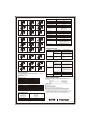
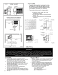
Powerware 5110 UPS
USER'S MANUAL
The Powerware 5110 uninterruptible power system (UPS) protects your
sensitive electronic equipment from power problems such as power failures,
power sags, power surges, brownouts, and line noise.
Features:
Processor-controlled voltage regulation
Eight outlets
-Four with surge and backup protection
-Four with surge protection only
Data Line (Internet fax - modem - DSL) or telephone line surge protection jacks
Cold start capability
USB communication port
User-replaceable batteries
SAFETY INSTRUCTIONS
Once you have received the Powerware 5110 UPS product, you should remove
and inspect the product for shipping damage. If any damage is found, please
notify the carrier and your dealer. Please keep the shipping carton and the
packing foam in the event the product must be returned to the factory for service.
ATTENTION: Maintenance must be performed by a qualified personnel. Failure
to do so could result in an electric shock. Replace Battery with Powerware
supplied Battery ONLY! Although the unit may be unplugged from utility power,
hazardous voltage still may be present through the battery.
1. Place the Powerware 5110 UPS indoors in an area that has adequate airflow
and is free from excessive dust. Do NOT allow the UPS to be exposed to
moisture, rain, excessive heat or direct sunlight.
2. Use of the Powerware 5110 UPS product in life support applications where
failure of this equipment can reasonably be expected to cause failure of life
support equipment or to significantly affect its safety or effectiveness is NOT
recommended.
3. Always disconnect the input power cord from the wall outlet before replacing
the battery.
4. When replacing the battery, use the same number and type of battery.
5. Do NOT dispose of the battery in a fire: the battery may explode.
6. Do NOT open or mutilate the battery. Batteries contain an electrolyte that is
toxic and harmful to both the skin and eyes.
7. Proper disposal of the battery is required. Please refer to your local
laws/regulations regarding battery disposal.
8. Use tools with insulated handles to replace the battery to avoid personal
injury. Due to energy hazards, please remove wristwatches and jewelry such
as rings when replacing battery.
BATTERY CONNECTION REQUIRED BEFORE USE!
Connecting the Battery:
4.5 AH, 5 AH batteries (350 VA, 500 VA models)
2
7AH x 2, 9AH x 2 batteries (1000VA, 1500VA models)
1
2
Push at the top Edge to remove the
battery cover
Slide down to remove the battery cover
3
4
Connect the battery cable
Reinstall the battery cover
INSTALLATION AND OPERATION:
Following steps explain how to connect and operate the Powerware 5110 UPS.
1. Connect the UPS to a grounded power outlet.
Note: It is recommended that the battery should be charged for minimum 8 hours
to ensure full charge before placing the UPS in service.
2. Plug your computer, monitor or load to be protected into the “Battery Backup &
Surge Protection” outlets. (These outlets will provide emergency battery
backup power during power outages as well as protection from surges and
spikes.)
CAUTION: Do NOT plug LASER PRINTERS into the “Battery Backup” outlets.
CAUTION: Do NOT plug ACCESSORY SURGE strips into the “Battery Backup”
outlets.
3. Plug your peripheral equipment or non-critical loads (printer, scanner, fax,
speaker, etc.) into the “Surge Protection” outlets. (These outlets provide surge
and spike protection only, they will NOT provide battery backup power during a
utility power failure).
4. Connect your computer to the UPS using USB cable provided.
5. With your equipment turned off, switch on the UPS.
6. When the “On/Off” LED light is illuminated, turn on the connected equipment.
7. Install Power management software provided with the UPS
INDICATORS
7
1
8
4
6
5
6
5
10
9
2
3
1.On/Off Push Button
Push button switch that controls power to the UPS and initiates the self-test
function.
Depress the push button to turn on the UPS.
Depress the push button again to turn off the UPS.
The UPS will perform a self-test for about 5 seconds when the UPS is turned on.
2.AC mode (Green) LED
Indicates that AC utility power is present and regulated power (AVR) is
applied to the connected equipment.
Push at the top Edge to remove the
battery cover
3
Slide down to remove the battery cover
4
3.Fault / Warning (Red) LED
Indicates that a fault condition has occurred.
-Flashing Red LED indicates an overload condition or that the battery should
be replaced.
-Solid On LED indicates that the output is shorted or an internal UPS fault exits.
See the Indicator Table below for further detail.
4.Backup mode (Yellow) LED
Pull out the battery and connect the battery
wire to the battery terminal
Reinstall the battery cover
Indicates that the UPS is operating on battery and providing regulated AC power
to the backup only outlets and the connected equipment.
5.Battery Backup & Surge Protection Outlets
Four 5-15R output receptacles that provide both backup and surge protection.
7 AH battery (700 VA models)
2
6.Surge Protection Outlets
Four 5-15R output receptacles that provide surge and spike protection only.
7.Data /Phone/Fax Protection Connectors
8.USB Communication Port
Push at the top Edge to remove the
battery cover
3
Pull out the battery and connect the battery
wire to the battery terminal
Slide down to remove the battery cover
4
Reinstall the battery cover
The built-in USB port connects to your computer. The LanSafe monitoring and
shutdown software provided can automatically save your files and shut down
your computer in the event of a prolonged power outage. The software also
provides information regarding the status of your utility power line.
9.Circuit Breaker (resetable)
The button will protrude when the overload condition occurs. If the button
protrudes, disconnect some non-essential equipment and reset the circuit
breaker by pushing the button inward.
10.Power Cord
6 foot line cord
BATTERY REPLACEMENT PROCEDURE:
1.Disconnect the UPS from the power source and slide the battery door open.
See pictures 1 and 2.
2.Disconnect the battery and remove as indicated below. See pictures 3 and 4
3.Insert the replacement battery and reconnect the battery cables.
See pictures 6 and 7
NOTE: It is important that the connectors be firmly attached to new batteries.
4.Reposition the battery door and slide closed. See pictures 8 and 9.
NOTE: Properly recycle used battery.
4.5AH, 5AH batteries (350VA, 500VA models)
1
2
3
50 / 60 Hz auto sensing
Frequency
8 Outlets (4 Battery Backup & Surge Protection;
4 Surge Protection only)
Outlets
4
7
5
8
15%
Automatic Voltage Regulation (AVR)
6
9
Lighting / Surge Protection
320 Joules
Transfer time to Battery/AC
6ms typical
Battery Type
Maintenance free lead-acid battery
Battery Specification
350 VA: 12V 4.5 Ah
500 VA: 12V 5 Ah
750 VA: 12V 7 Ah
1000 VA: (2) 12V 7 Ah
1500 VA: (2) 12V 9 Ah
Typical Backup Time
3 MINUTES MINIMUM AT FULL RATED LOAD
RJ11/RJ45
LAN / Phone / Fax Protection
Short Circuit Protection
Circuit Breaker
Communication Port
7AH x 1 battery (700VA models)
1
USB
Operation Temperature
2
3
0 C~40 C
0 to 95% non-condensing
Operation Relative Humidity
Storage Temperature
-15 C~50 C
350 VA: 11.9 pounds / 5.4 kg
500 VA: 12.13 pounds / 5.5 kg
700 VA: 15.21 pounds / 6.9 kg
1000 VA: 28 pounds / 12.7kg
1500 VA: 29.1 pounds / 13.2 kg
Net Weight
4
5
6
350 / 500 / 700 VA: 10.6 x 3.4 x 10 in.
1000 / 1500 VA: 10.6 x 3.4 x 15 in.
Dimensions (HxWxD)
* Due to continuing product improvement programs, specifications are subject to change
without notice.
7
8
9
TROUBLESHOOTING
Symptom
UPS will not turn on
7AH x 2, 9AH x 2 batteries (1000VA, 1500VA models)
1
2
Possible Cause
Action to Take
The UPS is not connected
to the power source.
Circuit Breaker has
tripped.
Ensure the UPS is securely
connected to an AC outlet.
Reduce the amount of equipment
plugged into the “Battery Backup &
Surge Protection” outlets of the
UPS. Reset the circuit breaker by
pushing it back in. Switch the UPS
back on.
3
Turn off the UPS and reduce the
The “Battery Backup &
UPS is making a
continuous sound and the Surge Protection” outlets amount of equipment connected to
these outlets.
“Overload” indicator is on are overload.
4
7
5
8
6
UPS does not provide
expected runtime
9
UPS does not power
essential equipment
during an outage
Status Indicators
The UPS provides both visual and audible status indicators. Visual indicators
consist of three LEDs to represent the following conditions:
On utility power operation
On battery power operation
UPS fault/alarm
LED Indicator Table
On Utility (AC mode)
On Battery (Backup mode)
Low Battery
Fault/Output Short
Overload/Check Battery
Sounding every 5 seconds
Sounding (two beeps) every 5 seconds
Sounding every 0.5 seconds
Sounding (three beeps) every 30 seconds
Continuous sounding
Sounding (three beeps) every 5 seconds
SPECIFICATIONS
Model Numbers
PW5110 350 USB
PW5110 500 USB
PW5110 700 USB
PW5110 1000 USB
PW5110 1500 USB
Charge the battery for 8 hours. The
UPS runtime is reduced until the
battery is fully charged.
Unplug non-essential equipment
(printers, scanners, etc) from the
Battery Backup outlets and plug
into 'Surge Only' outlets
Disconnect non-essential equipment
from the UPS. Reset (push in) the
circuit breaker and switch the UPS on.
Plug equipment in one-at-a-time. If
the circuit breaker trips again,
disconnect the device that caused the
breaker to trip.
The battery has reached Replace the battery or the battery
module.
the end of its life.
Equipment plugged into a Unplug device from 'Surge Only' outlet
Surge Only outlet.
and move to a 'Battery Backup outlet.
Internal UPS fault.
Contact Technical Support (see
Service and Support below).
SERVICE AND SUPPORT
Green Lighting
Yellow Lighting
Yellow Flashing
Red Lighting
Red Flashing
LED Audible Alarm Table
Backup mode
Battery low
Overload
Replace battery
Fault or output short circuit
Battery over charge
Red LED Indicator ON
The UPS battery is
discharged due to a power
outage and has not
recharged.
Devices plugged into Back
up & surge protection
receptacles exceed the
rated load for the UPS run
time
The UPS circuit breaker
tripped .
For questions and/or problems, please call your local distributor or the
help desk at one of the following telephone numbers and ask for a UPS technical
representative.
United States:
1.800.356.5737
Europe, Middle East, and Africa:
+44.17.53.608.700
Asia:
+852.2830.3030
Australia:
+61.3.9706.5022
Please have the following information ready when you call the Help Desk:
Model number
Serial number
Version number (if available)
Date of failure or problem
Symptoms of failure or problem
Customer return address and contact information
If repair is required, you will be given a Returned Material Authorization
(RMA) Number. This number must appear on the outside of the package
and on the Bill of Lading (if applicable). Use the original packaging or
request packaging from the Help Desk or distributor. Units damaged in shipment
as a result of improper packaging are not covered under warranty.
A replacement unit will be shipped, freight prepaid for all units under warranty.
For additional information please visit us online: www.powerware.com
Capacity
350 VA / 210W
500 VA / 300W
700 VA / 420W
1000 VA / 600W
1500 VA / 900W
Nominal Input Voltage
120Vac
Nominal Output Voltage
120Vac
MA6B411003A(2005/01/25)