1
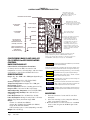
INSTALLATION INSTRUCTIONS
I-TEC SERIES
PACKAGED HEAT PUMP
Models:
I30H1-A
I30H1-B
I30H1-C
I36H1-A
I36H1-B
I36H1-C
I42H1-A
I42H1-B
I42H1-C
I48H1-A
I48H1-B
I48H1-C
I60H1-A
I60H1-B
I60H1-C
I30H1DA
I30H1DB
I30H1DC
I36H1DA
I36H1DB
I36H1DC
I42H1DA
I42H1DB
I42H1DC
I48H1DA
I48H1DB
I48H1DC
I60H1DA
I60H1DB
I60H1DC
MIS-2957 A
Bard Manufacturing Company, Inc.
Bryan, Ohio 43506
www.bardhvac.com
Manual:2100-549L
Supersedes:2100-549K
Date:2-11-15
Page
1 of 59
CONTENTS
Getting Other Information and Publications
For More Information, Contact These Publishers:.......... 3
General & ANSI Z535.5 Definitions........................... 4
I-TEC General Information
I-TEC Model Nomenclature........................................ 5
Shipping Damage, Unit Removal From Skid................. 8
Handling Unit After Removal From Skid...................... 8
Required Steps after Final Placement......................... 9
Minimum Installation Height...................................... 9
Securing Unit to Structure & Seismic Considerations.... 9
Duct Work, Supply Duct Connections & Filters........... 17
Condensate Drain.................................................... 18
With No Vent Option and With CRV & ERV................. 18
Installation Instructions
Mounting the Unit & Wiring – Main Wiring................. 21
Wiring – Low Volt. Wiring & Low Volt.Connections....... 22
Start Ups
R-410A Refrigerant Required................................... 30
Topping Off System Charge...................................... 30
Safety Practices...................................................... 30
Description of Standard Equipment........................... 31
Important Installer Note........................................... 31
Phase Monitor......................................................... 31
Three Phase Scroll Compressor................................. 31
Figures
Figure 1 Unit Dimensions........................................ 7
Figure 2A & 2B Unit on Lift & Unit Side..................... 8
Wall Mounting Bracket Location.................................. 9
Bracket Wall Sect. View & Wood Framed Install.......... 10
Figure 3 Center of Gravity...................................... 11
Figure 4 Req. Clearances & Rec. Access................. 12
Figure 5 Compressor Shipping Bolts....................... 13
Figure 6 Removal of Air Duct................................. 13
Figure 7A Ducted Application................................... 14
Figure 7B3" Riser Application................................. 15
Figure 7C 6" Riser Application................................. 16
Figure 8 Supply Duct Connections.......................... 17
Figure 9 Filter Location......................................... 17
Figure 10 Drain Locations........................................ 18
Figures 11A & 11B Unit Mounting....................19 & 20
Figure 12 Component Location................................. 21
Figure 13 Basic Heat Pump w/No Vent Pkg............... 23
Figure 14 HP w/CRV, without CO2 Control.................. 24
Figure 15 HP with CRV & CO2 Control....................... 25
Figure 16 HP with ERV, w/o CO2 Control.................... 26
Figure 17 HP with ERV & CO2 Control....................... 27
Figure 18 HP w/ERV & CO2 Control (Fully Mod.)........ 28
Figure 19 HP w/Comb. CRV & DB Econ. ("N" Vent)....... 29
Figure 20 Defrost Cycle........................................... 33
Figure 21 CRV Motor Speed/CFM Configuration......... 35
Figure 22 CRV Speed Change Terminal Access.......... 36
Figure 23 Economizer Control Circuit........................ 38
Figure 24 Motor Speed / CFM Configuration.............. 39
Fig. 25A ERV Manual Mode "M" Terminal................ 43
Fig. 25B ERV Mod. Mode "P" Terminal.................... 43
Figure 26 Ventilation Airflow Diagram....................... 44
Figure 27 ERV Control Access.................................. 45
Figure 28 Control Board Config./Setting.................... 46
Manual2100-549L
Page
2 of 59
Service Hints.......................................................... 31
Sequence of Operation............................................. 32
Pressure Service Ports............................................. 32
Lowering Outdoor Fan Speed for Sound..................... 32
Defrost Cycle.......................................................... 33
I-TEC Commercial Room Ventilator System
Gen. Description, Control Wiring & Rec. Seq.............. 34
Setting the Ventilation CFM Levels............................ 34
I-TEC Comb. CRV & Economizer Vent System
Description & Control Wiring..................................... 37
Setting the Ventilation CFM Levels............................ 37
Economizer Seq. of Operation................................... 38
Heating & Vent Mode .............................................. 39
I-TEC Energy Recovery Ventilator System
General Description & Control Wiring......................... 40
Recommended Control Sequences............................ 41
Changing Ventilation CFM Rates in Manual Mode....... 41
Changing to Fully Modulating Mode.......................... 41
Configuring Control for ERV Mod. Control................... 47
Maintenance (Gen., Frequency, Clean & Perform.)......... 49
Troubleshooting
Solid State HP Control Troubleshooting Procedure......51
Checking Temperature Sensor...................................52
Troubleshooting ECM™ 142R Motor.........................53
Replacing the Motor................................................54
Troubleshooting Indoor ECM™ Motor........................55
Fan Blade Setting Dimensions..................................57
Refrigerant Charge...................................................57
Figures (continued)
Figure 29 Hub Assembly w/Ball Bearings.................. 50
Figure 30 Control Disassembly................................. 56
Figure 31 Winding Test............................................ 56
Figure 32 Drip Loop................................................ 56
Figure 33 Control Connector Motor Half.................... 57
Tables
Table 1 Factory Built-In Electric Heat Table............... 5
Table 1A Indoor Blower Performance.......................... 5
Table 2 Elec. Specifications..................................... 6
Center of Gravity Reference Table............................. 11
Table 3 Operating Voltage Range............................ 22
Table 4 Wall Thermostats...................................... 22
Low Voltage Connections for DDC Control.................. 22
Performance & App. Data:
Summer Cooling & Winter Heating............................ 42
Table 5 Troubleshooting......................................... 51
Table 6 Temp. vs Resistance of Temp. Sensor.......... 52
Table 7 Troubleshooting ECM™ 142R.................... 54
Table 8 Cooling Mode............................................ 54
Table 9 Heat Pump Mode...................................... 54
Troubleshooting ECM™ Blower Motors...................... 57
Power Connector..................................................... 57
Table 10APressures: Full Load Cooling...................... 58
Table 10BPressures: Full Load Heating...................... 58
Table 11APressures: Part Load Cooling ..................... 59
Table 11BPressures: Part Load Heating..................... 59
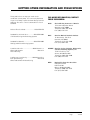
GETTING OTHER INFORMATION AND PUBLICATIONS
These publications can help you install the air
conditioner or heat pump. You can usually find these
at your local library or purchase them directly from the
publisher. Be sure to consult current edition of each
standard.
National Electrical Code...................... ANSI/NFPA 70
Standard for the Installation.............. ANSI/NFPA 90A
of Air Conditioning and Ventilating Systems
Standard for Warm Air....................... ANSI/NFPA 90B
Heating and Air Conditioning Systems
Load Calculation for .......................ACCA Manual J or
Winter and Summer
Manual N
Air Conditioning
Low Pressure, Low Velocity............. ACCA Manual D or
Duct System Design Manual Q
Winter and Summer Air Conditioning
FOR MORE INFORMATION, CONTACT
THESE PUBLISHERS:
ACCA
Air Conditioning Contractors of America
1712 New Hampshire Avenue
Washington, DC 20009
Telephone: (202) 483-9370
Fax: (202) 234-4721
ANSI
American National Standards Institute 11 West Street, 13th Floor
New York, NY 10036
Telephone: (212) 642-4900
Fax: (212) 302-1286
ASHRAE
American Society of Heating, Refrigeration, and Air Conditioning Engineers, Inc.
1791 Tullie Circle, N.E.
Atlanta, GA 30329-2305
Telephone: (404) 636-8400
Fax: (404) 321-5478
NFPA
National Fire Protection Association
Batterymarch Park
P.O. Box 9101
Quincy, MA 02269-9901
Telephone: (800) 344-3555
Fax: (617) 984-7057
Manual2100-549L
Page
3 of 59
GENERAL
The equipment covered in this manual is to be installed
by trained, experienced service and installation
technicians.
The I-TEC must be installed with the Bard manufactured IWS wall sleeve and ILG louver grille accessories. These are sold as separate accessories. Any substitutions will void the manufacturer’s warranty.
The unit is designed for use with or without ductwork.
For use without ductwork, Plenum Box IPBDF8color (8" height) or IPBDF12-color (12" height) is
recommended.
These instructions explain the recommended method
to install the air cooled self-contained unit and the
electrical connections to it.
These instructions and any instructions packaged
with any separate equipment required to make up the
entire heating and air conditioning system should be
carefully read before beginning the installation. Note
particularly “Start Procedure” and any tags and/or
labels attached to the equipment.
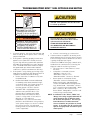
ANSI Z535.5 Definitions:
• Danger: Indicate[s] a hazardous situation which, if
not avoided, will result in death or serious injury. The
signal word “DANGER” is to be limited to the most
extreme situations. DANGER [signs] should not be used
for property damage hazards unless personal injury risk
appropriate to these levels is also involved.
• Warning: Indicate[s] a hazardous situation which,
if not avoided, could result in death or serious injury.
WARNING [signs] should not be used for property
damage hazards unless personal injury risk appropriate
to this level is also involved.
• Caution: Indicate[s] a hazardous situation which, if
not avoided, could result in minor or moderate injury.
CAUTION [signs] without a safety alert symbol may be
used to alert against unsafe practices that can result in
property damage only.
• Notice: [this header is] preferred to address
practices not related to personal injury. The safety alert
symbol shall not be used with this signal word. As an
alternative to “NOTICE” the word “CAUTION” without
the safety alert symbol may be used to indicate a
message not related to personal injury.
Manual2100-549L
Page
4 of 59
While these instructions are intended as a general
recommended guide, they do not supersede any
national and/or local codes in any way. Authorities
having jurisdiction should be consulted before the
installation is made. See Page 3 for information on
codes and standards.
Size of unit for a proposed installation should be based
on heat loss or heat gain calculation made according
to methods of Air Conditioning Contractors of America
(ACCA). The air duct should be installed in accordance
with the Standards of the National Fire Protection
Systems of Other Than Residence Type, NFPA No.
90A, and Residence Type Warm Air Heating and Air
Conditioning Systems, NFPA No. 90B. Where local
regulations are at a variance with instructions, installer
should adhere to local codes.
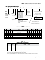
I-TEC Series General Information
I-TEC MODEL NOMENCLATURE
I
36 MODEL
SERIES
H
1
D
A 0Z
SYSTEM TYPE
HEAT PUMP
NOMINAL
CAPACITY
30 – 30,000 BTUH
36 – 36,000
42 – 42,000
48 – 48,000
60 – 60,000
R
P
SPECIAL UNITS
(–) – Standard
D – Dehum.
VOLTS & PHASE
A – 230/208, 60-1
B – 230/208, 60-3
C – 460-60-3
X
X
1–
2–
3–
4–
FILTER OPTIONS
P – 2" Pleated MERV 8
M – 2" Pleated MERV 11
N – 2" Pleated MERV 13
VENTILATION OPTIONS
B – Blank-Off Plate
M – Multi-Speed CRV
N – Comb. CRV & DB Economizer
R – ERV
RESERVED
2
CONTROLS
X – 24V Terminal Block Only w/o COLOR OPTIONS
X – Beige paint
1 – White paint
4 – Gray paint
ELECTRIC HEAT
0Z – No heat w/breaker
04 – 4KW 1-Phase
05 – 5KW 1-Phase
06 – 6KW 3-Phase
09 – 9KW 3-Phase
10 – 10KW 1-Phase
15 – 15KW 1 & 3-Phase
18 – 18KW 3-Phase
20 – 20KW 1-Phase
REVISION
4
CompleteStat
CompleteStat THO (Temp, Humidity & Occupancy)
CompleteStat THO w/CO2
CompleteStat THO w/Ethernet
CompleteStat THO w/CO2 & Ethernet
Note: CompleteStat must be field
installed & wired. All units have
24V terminal block.
COIL TREATMENT
X – Std. Hydrophilic Fin Evap. & Uncoated Alum. Cond. Coil
1 – Phenolic Coated ID Coil
2 – Phenolic Coated OD Coil
3 – Phenolic Coated ID & OD Coil
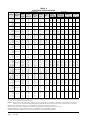
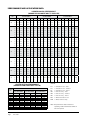
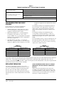
TABLE 1
FACTORY BUILT-IN ELECTRIC HEAT TABLE
Models
KW
I30H1-A
I30H1-B
I36H1-A
I42H1-A
I30H1-C
I36H1-B
I42H1-B
I36H1-C
I42H1-C
BTUH
BTUH
I48H1-C
I60H1-C
I60H1-A
BTUH
BTUH
BTUH
BTUH
BTUH
BTUH
BTUH
BTUH
BTUH
BTUH
BTUH
BTUH
BTUH
BTUH
BTUH
13,652 10,239
17,065 12,799
6.0
17,065 12,799
20,478 15,359 20,478
9.0
10.0
I48H1-B
I60H1-B
240V-1 208V-1 240V-3 208V-3 460V-3 240V-1 208V-1 240V-3 208V-3 460V-3 240V-1 208V-1 240V-3 208V-3 460V-3 240V-1 208V-1
4.0
5.0
I48H1-A
30,717 23,038 30,717
34,130 25,598
17,065 12,799
20,478 15,359 20,478
30,717 23,038 30,717
34,130 25,598
15.0
17,065 12,799
20,478 15,359 20,478
30,717 23,038 30,717
34,130 25,598
34,130 25,598
51,195 38,396 51,195 38,396 51,195 51,195 38,396 51,195 38,396 51,195 51,195 38,396
18.0
61,434 46,076 61,434
20.0
68,260 51,195
68,260 51,195
TABLE 1A
INDOOR BLOWER PERFORMANCE
MODEL
Rated
ESP
MAX
ESP
k
Continuous
Airflow
Rated 2nd
Stage CFM
Rated 1st
Stage CFM
l
5 – 9KW
CFM
m
13.5 – 18KW
CFM
I30H1
.15
0.50
500
900
650
700
1400
I36H1
.15
0.50
600
1150
850
700
1400
I42H1
.20
0.50
650
1300
950
700
1400
I48H1
.20
0.50
725
1500
1050
700
1400
I60H1
.20
0.50
850
1700
1200
700
1400
Motor will deliver consistent CFM through voltage supply range with no deterioration.
Continuous fan CFM is the total air being circulated during continuous fan mode.
Will operate at rated Full Load Airflow when operating with Heat Pump.
Will occur automatically with a call for "W3" or "Emergency Heat" signal from the thermostat (Heat Pump Operation is terminated at this condition).
Manual2100-549L
Page
5 of 59
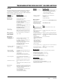
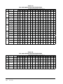
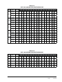
TABLE 2
ELECTRICAL SPECIFICATIONS
MODEL
I30H1-A0Z
A05
A10
I30H1-B0Z
B06
B09
I30H1-C0Z
C06
C09
I36H1-A0Z
A05
A10
A15
I36H1-B0Z
B06
B09
B15
I36H1-C0Z
C06
C09
C15
I42H1-A0Z
A05
A10
A15
I42H1-B0Z
B06
B09
B15
I42H1-C0Z
C06
C09
C15
I48H1-A0Z
A04
A05
A10
A15
A20
I48H1-B0Z
B06
B09
B15
B18
I48H1-C0Z
C06
C09
C15
C18
I60H1-A0Z
A05
A10
A15
A20
I60H1-B0Z
B06
B09
B15
B18
I60H1-C0Z
C06
C09
C15
C18
Rated
No. Field
Volts, Hertz
Power
& Phase
Circuits
230/208-1
230/208-3
460-3
230/208-1
230/208-3
460-3
230/208-1
230/208-3
460-3
230/208-1
230/208-3
460-3
230/208-1
230/208-3
460-3
1
1
1 or 2
1
1
1
1
1
1
1
1
1 or 2
1 or 2
1
1
1
1
1
1
1
1
1
1
1 or 2
1 or 2
1
1
1
1
1
1
1
1
1
1
1 or 2
1 or 2
1 or 2
1 or 2
1
1
1
1
1
1
1
1
1
1
1
1 or 2
1 or 2
1 or 2
1 or 2
1
1
1
1
1 or 2
1
1
1
1
1
Single Circuit
Maximum
Minimum
Field
External
Circuit
Power Wire
Fuse or Ckt.
Ampacity
Size
Brkr.
8
35
22
8
50
48
4
80
74
10
25
17
8
35
35
8
45
44
14
10
9
12
20
18
10
25
22
26
40
8
52
60
6
78
80
4
84
90
4
22
30
10
40
45
8
49
50
8
51
60
6
11
15
14
20
20
12
24
25
10
28
30
10
30
45
8
56
60
6
82
90
4
82
90
4
25
35
8
43
50
8
52
60
6
52
60
6
12
15
14
21
25
10
26
30
10
28
30
10
34
50
8
54
60
6
59
70
6
85
90
3
85
90
3
110
110
2
8
35
26
8
50
44
6
60
53
6
60
53
6
60
53
12
20
12
10
30
21
10
30
26
10
30
26
10
30
26
8
60
44
4
80
70
3
100
96
3
100
96
2
120
112
8
45
31
8
60
49
6
60
58
6
60
58
6
70
63
12
20
15
10
30
25
10
30
29
10
30
29
10
30
29
Ground
Wire
10
10
8
10
10
10
14
12
10
10
10
8
8
10
10
10
10
14
12
10
10
10
10
8
8
10
10
10
10
14
10
10
10
10
10
8
8
8
6
10
10
10
10
10
12
10
10
10
10
10
8
8
8
6
10
10
10
10
8
12
10
10
10
10
Dual Circuit
Maximum
Minimum
Field Power
External Fuse or
Circuit
Wire Size
Ckt. Breaker
Ampacity
Ckt. A Ckt. B Ckt. A Ckt. B Ckt. A Ckt. B
Ground Wire
Size
Ckt. A
Ckt. B
48
30
50
30
8
10
10
10
26
26
52
52
40
40
60
60
8
8
6
6
10
10
10
10
56
56
26
52
60
60
30
60
6
6
10
6
10
10
10
10
35
35
35
59
26
52
52
52
45
45
45
60
30
60
60
60
8
8
8
6
10
6
6
6
10
10
10
10
10
10
10
10
44
44
44
60
26
52
52
52
60
60
60
60
30
60
60
60
8
8
8
6
10
6
6
6
10
10
10
10
10
10
10
10
31
54
45
60
8
6
10
10
These “Minimum Circuit Ampacity” values are to be used for sizing the field power conductors. Refer to the National Electric Code (latest
revision), article 310 for power conductor sizing.
Caution: When more than one field power conductor circuit is run through one conduit, the conductors must be derated. Pay special
attention to note 8 of table 310 regarding Ampacity Adjustment Factors when more than three conductors are in a raceway.
Maximum size of the time delay fuse or circuit breaker for protection of field wiring conductors.
Based on 75°C copper wire. All wiring must conform to the National Electrical Code and all local codes.
Maximum KW that can operate with heat pump on is 10KW for 1-Phase and 9KW for 3-Phase.
Represents Electric Heat Only. Electrical Control Circuit will lockout Heat Pump Operation.
Manual2100-549L
Page
6 of 59
Manual2100-549L
Page
7 of 59
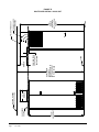
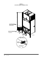
1
24"
Front Forklift Holes
(Remove Front Trim)
13 4 "
1
5
58"
3
Side Forklift Holes
(Remove Sides)
1
22 4 "
Lower
Section
71 4 "
Upper
Section
94"
Total
Height
15 8 "
Locking
Door Latch
Electrical
Disconnect
Locking
Door Latch
(4) Lift-Off
Hinges
High Voltage
7
Entrance
11 8 "
Electric Heat
Wire Channel
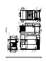
30" With Doors and
Sides Removed
Right Side View
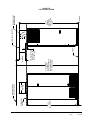
1
24 2 "
1
71 2 "
Outer
Sleeve
Inner
Sleeve
Return
Air
(2) Return
Openings
3
34"
8"
1
38"
Supply
Air
1
38"
MIS-2917 A
(2) Opt.
Unit Drain
Entrances
Inner
Sleeve
Outer
Sleeve
Return
Air
Back View
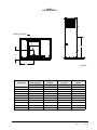
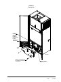
Unit Specification Sheet
(2) Unit
Drains
2"
3
31 8 "
Total Depth
26 4 "
3
20" x 24" Supply Frame
(2) 12" x 20"
Vent Exhaust
Air Filters
Low Voltage
Entrance
20"
(2) Side
Handles
1
11 4 "
5
47 8 " Total Width
1
46 8 " With Sides Removed
(2) Washable
Vent Intake
Air Filters
Control Panel
(2) 2"x24"x30"
Return Air
Filters
Front View
24"
28 4 "
1
34"
1
Top View
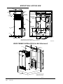
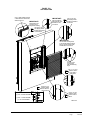
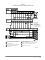
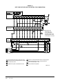
FIGURE 1
UNIT DIMENSIONS
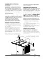
SHIPPING DAMAGE
Upon receipt of equipment, the unit should be checked
for external signs of shipping damage. The skid must
remain attached until the unit is ready for installation.
If damage is found, the receiving party must contact
the last carrier immediately, preferably in writing,
requesting inspection by the carrier’s agent.
UNIT REMOVAL FROM SKID
WARNING
This unit is heavy and requires more than one person
to handle during installation and removal from the skid.
Extreme caution must be taken to prevent injury to
personnel and damage to the unit. Use appropriate safety
equipment, including gloves when handling. Failure to do
so may result in serious injury.
A forklift or a lift rated for the load (Figure 2A) is
required to lift the unit off from the skid. This unit is
top heavy and should never be tipped while moving it.
The I-TEC is designed to be lifted off the skid from the
front or rear of the unit without having to remove any
doors or side panels. See Figure 1 for fork openings.
The shipping brackets on front and rear of the unit
must be removed and discarded. The unit can now
be lifted straight up and the skid can be slid out from
underneath.
Tip unit from left side only.
Failure to do so may result in injury due to unit topheaviness or compressor damage!
FIGURE 2A – UNIT ON LIFT
HANDLING UNIT AFTER REMOVAL
FROM SKID
If a wide and tall enough opening exists, the I-TEC can
be moved as a complete assembled unit. If not, it is
designed to break down into two sections to allow it to
pass through a 36 inch wide door.
1. Depress & release both top & bottom door latches and
open doors.
2. Remove the doors by lifting straight up and off from
the hinge pins.
3. Remove cabinet sides by first removing the four (4)
sheet metal screws from the front (leading edge) of the
side panel. The panel will not fall off. Swing the panel
away from the chassis 20 to 30 degrees & then pull
forward from the two (2) tabs supporting the rear edge.
4. On each side of the unit is a tie plate that secures
the top and bottom sections with four (4) cap bolts.
Using a ½ inch wrench or socket, remove these
screws from both plates and set aside.
5. If the unit is equipped with a CRV or ERV, you must
unplug the wire harness on the left-hand side of the
control box.
6. A forklift or a lift rated for the load is required to lift
the top section off from the bottom base. Do not
attempt to do this manually. Failure to do so could
result in the unit tipping over & causing bodily injury
and/or damage to the unit.
7. The top section can be forked from either the RH or
LH side. See Figure 1 for fork openings.
8. Carefully lift the top section straight up avoiding tipping.
9. Move the top section through the doorway and place
on flat surface free of debris.
10.The bottom base can now be moved through the
doorway the same way.
11.Reassemble the unit by reversing this procedure.
FIGURE 2B – UNIT SIDE
ERV/CRV
HARNESS CONNECTION
(4) CAP BOLTS
FORK OPENING
(Visible after removing
tie plate)
TIE PLATE
(Covers entire width; shortened for illustration
purposes to show Fork Openings)
Manual2100-549L
Page
8 of 59
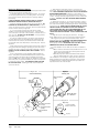
REQUIRED STEPS AFTER FINAL
PLACEMENT
The compressor is secured to the base with two (2)
bolts for shipping. Although the unit will perform as
designed with the shipping bolts in place, there may
be a noticeable additional noise and vibration noted.
To obtain the lowest noise and vibration levels, remove
the shipping bolts after the unit is in its final operating
location. To gain access to the compressor, the
compressor access panel must be removed (Figure 9).
Once this panel is removed, the CRV/ERV air duct must
be removed. See Figure 6.
The air duct is removed by pulling it straight toward
you; there are no screws securing it in place. Both the
top and bottom slide toward you at the same time (pull
hard). Once removed, the compressor is visible as well
as the tags on the shipping bolts (Figure 5).
After the compressor shipping bolts have been
removed, the CRV/ERV air duct can be slid back in
place and the compressor access panel attached.
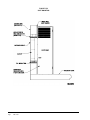
MINIMUM INSTALLATION HEIGHT
The minimum installation height to the bottom of the
roof or fixed ceiling for ducted applications is 9 ft. 7
in. This provides enough clearance to install the duct
work. See Figure 7A.
The IWS Series wall sleeve has a built-in vertical
adjustment to fit window sill heights from 31-34
inches. If additional height is required, two riser
platform accessories are available. The IRP3 increases
the unit height by 3 inches (Figure 7B) and the IRP6
by 6 inches (Figure 7C).
Several construction options are available for unit
installation of the IZ Series. Serviceability and filter
2"
1 11/16"
access must be considered before installing. See
Figure 5D for required clearances and recommended
service access dimensions.
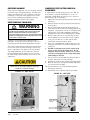
SECURING UNIT TO STRUCTURE
Shipped with the I-TEC unit is a wall mounting bracket
(screwed to shipping skid on backside of unit). This
bracket can be utilized to secure the top portion of the
unit to the wall using the appropriate field supplied
hardware based upon the material you are fastening
to. (There are several offset holes, sized to accept up
to a 1/4" diameter fastener that will easily allow you to
hit studs on a framed wall.) See BRACKET SECTION
VIEW for locating this top wall bracket which will
need to be applied after the unit is located in the final
position.
Additional/optional mounting holes for up to a 3/8"
diameter fastener are also available in the backside of
the unit. These can be accessed by:
• removing the air filters for the uppermost set
• removing the compressor section service door for
the lower set
Refer to WOOD FRAMED INSTALLATION for additional
framing required to secure unit to wall.
The additional/optional mounting holes will require a
long extension to drive the fasteners.
SEISMIC CONSIDERATIONS
The I-TEC product features several locations for
product securement but all site conditions are
different. Consult with a licensed Seismic Engineer
to advise of particular needs when attaching the I-TEC
unit to the structure.
43 3/8"
Ø1/4"
WALL MOUNTING BRACKET LOCATION
BRACKET
3/4"
1 1/2"
7/8"
94" FROM BOTTOM
OF BRACKET TO
FLOOR WITHOUT
RISER KIT
MIS-3029
Manual2100-549L
Page
9 of 59
RISER KIT
NONE
IRP-3 (3")
IRP-6 (6")
DIM A
31"-34" MAX
34"-37" MAX
37"-40" MAX
Optional
Duct
DIM B
29 17/32"
32 17/32"
35 17/32"
DIM C
94 1/8"
97 1/8"
100 1/8"
Wall Section View
BRACKET WALL SECTION VIEW
Optional Top
Bracket
Outside
Wall
Ceiling
Optional
Trim or
Supply Duct
Box
(4) optional Unit
Mounting holes
Telescoping
Wall Sleeve**
7
7
20 8 "
20 8 "
Sleeve Mounting
Hole Locations
Centered on
Opening
Outside
Wall
3"
3
43 8 "
6"
Centered
20"
42-3/4" Min.
43-1/4" Max.
DIM C
48" Min.
48-1/2" Max.
Grille
3
49 8 "
Centered
1
56 2 "
20"
(4) optional Unit
Mounting holes
Unit
31" Min. *
34" Max.
DIM A
*
7
20 8 "
8"
15
1 16 "
20"
Room Floor Level
CL
18 3/4
CL
7 3/8
17.5"
35"
Right Side View
DIM B
20"
7
43 8 "
Floor
11
4 16 "
8"
Front (Wall Only) View
* Higher Sill Heights Acheivable With Base Kit.
** Separate telescoping sleeves available for different wall thicknesses.
MIS-2918 D
WOOD FRAMED INSTALLATION (for Wall Attachment)
41.75
Inner wall
(4) Upper
fastener holes
6.00
Unit
(4) lower fastener
holes
56.50
29.56*
8.00
20.88
36.88
Floor
8.00
* Height dimension shown without
riser kit. If unit uses riser kit add
appropriate dimension to height.
MIS-3072
Manual2100-549L
Page
10 of 59
FLOOR MOUNTING HOLE
& CENTERLINES
FIGURE 3
CENTER OF GRAVITY
CENTER OF GRAVITY
"Z"
"X"
"Y"
UNIT TESTED
MIS-3269
FRONT OF UNIT
DOOR TO CENTER
LEFT SIDE
TO CENTER
FLOOR TO CENTER
CRV & ERV
FLOOR TO CENTER
NO VENT
"X" Dimension
"Y" Dimension
"Z" Dimension
"Z" Dimension
I30H1-A, -B
14"
24"
43½"
47"
I30H1-C
14"
24¼"
43½"
47"
I36H1-A, -B
14"
24"
43½"
47"
I36H1-C
14"
24¼"
43½"
47"
I42H1-A, -B
14"
24"
43½"
47"
I42H1-C
14"
24¼"
43½"
47"
I48H1-A, -B
14"
24"
43½"
47"
I48H1-C
14"
24¼"
43½"
47"
I60H1-A, -B
14"
24"
43½"
47"
I60H1-C
14"
24¼"
43½"
47"
Manual2100-549L
Page
11 of 59
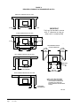
FIGURE 4
REQUIRED CLEARANCES & RECOMMENDED ACCESS
WING WALL CONSTRUCTION TOP VIEW
12" MIN.
12" MIN.
IMPORTANT
Unit can be located in corner
with 0" clearance as long as
other side is unobstructed
CLOSET CONSTRUCTION TOP VIEW
31 3/8"
12" MIN.
12" MIN.
12" MIN.
12" MIN.
48" MIN.
RECOMMENDED SERVICE
ACCESS DIMENSIONS
12" MIN.
FOR LEFT
SIDE
ACCESS
12" MIN.
FOR RIGHT
SIDE
ACCESS
LEFT CORNER CONSTRUCTION TOP VIEW
FILTERS
24" MIN.
24" MIN.
0" REQUIRED
12" RECOMENDED
REMOVABLE
SIDES 1
48"
MIN. FOR
FILTER ACCESS
RIGHT CORNER CONSTRUCTION TOP VIEW
0" REQUIRED
12" RECOMENDED
1 ALL FILTER AND COMPONENT
ACCESS IS FROM THE FRONT.
COILS CAN BE CLEANED FROM
THE FRONT, BUT SIDES ARE
EASILY REMOVED FOR ENHANCED
ACCESS.
MIS-3273
Manual2100-549L
Page
12 of 59
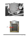
FIGURE 5
COMPRESSOR SHIPPING BOLTS
COMPRESSOR
SHIPPING BOLT
COMPRESSOR
SHIPPING BOLT
FIGURE 6
REMOVAL OF AIR DUCT
CRV/ERV
AIR DUCT
Manual2100-549L
Page
13 of 59
Manual2100-549L
Page
14 of 59
7'-9 3/4"
UNIT HEIGHT
SUSPENDED
CEILING
20"
MINIMUM
BOTTOM OF ROOF
OR FIXED CEILING
9'-7" MINIMUM
CLEARANCE
RECOMMENDED TO
BOTTOM OF ROOF
OR FIXED CEILING
FLOOR
4" MINIMUM FROM
TOP OF UNIT TO
DUCT BOTTOM
12"
MINIMUM
MIS-2958 B
9'-2"
MINIMUM
REQUIRED
INSTALLATION
HEIGHT
TURNING VANES
RECOMMENDED
FIELD SUPPLIED DUCT
FIGURE 7A
DUCTED APPLICATION – BASIC UNIT
3" RISER
7'-9 3/4"
UNIT HEIGHT
SUSPENDED
CEILING
20"
MINIMUM
BOTTOM OF ROOF
OR FIXED CEILING
9'-10" MINIMUM
CLEARANCE
RECOMMENDED TO
BOTTOM OF ROOF
OR FIXED CEILING
FLOOR
4" MINIMUM FROM
TOP OF UNIT TO
DUCT BOTTOM
12"
MINIMUM
FIELD SUPPLIED DUCT
MIS-2989 B
9'-5"
MINIMUM
REQUIRED
INSTALLATION
HEIGHT
TURNING VANES
RECOMMENDED
FIGURE 7B
3" RISER APPLICATION
Manual2100-549L
Page
15 of 59
Manual2100-549L
Page
16 of 59
6" RISER
7'-9 3/4"
UNIT HEIGHT
SUSPENDED
CEILING
20"
MINIMUM
BOTTOM OF ROOF
OR FIXED CEILING
10'-1" MINIMUM
CLEARANCE
RECOMMENDED TO
BOTTOM OF ROOF
OR FIXED CEILING
FLOOR
4" MINIMUM FROM
TOP OF UNIT TO
DUCT BOTTOM
12"
MINIMUM
TURNING VANES
RECOMMENDED
MIS-2988 B
9'-8"
MINIMUM
REQUIRED
INSTALLATION
HEIGHT
FIELD SUPPLIED DUCT
FIGURE 7C
6" RISER APPLICATION
DUCT WORK
Any heat pump is more critical of proper operating
charge and an adequate duct system than a straight air
conditioning unit. All duct work must be properly sized
for the design airflow requirement of the equipment.
Air Conditioning Contractors of America (ACCA) is
an excellent guide to proper sizing. All duct work or
portions thereof not in the conditioned space should
be properly insulated in order to both conserve energy
and prevent condensation or moisture damage. When
duct runs through unheated spaces, it should be
insulated with a minimum of one inch of insulation.
Use insulation with a vapor barrier on the outside of the
insulation. Flexible joints should be used to connect
the duct work to the equipment in order to keep the
noise transmission to a minimum.
The I-TEC series heat pump has provision to attach a
supply air duct to the top of the unit. Duct connection
size is 20 inches x 24 inches. The flanges are shipped
flat and must be bent upward using sheet metal
flanging pliers. The duct work is field supplied. See
Figure 8 for suggested attachment method.
Make sure to seal the slots in the bend-up flange at the
time of securing your ductwork to the flange. This can
be accomplished with either foil tape or caulk. Failing
to do so may cause air leakage/whistling of air.
mounted install (9'-9" with IRP3 riser & 10'-0" with
IRP6 riser). The ICX10 extends 28" above the unit for
a total height of 10'-2" for a floor mounted install (10'5" with IRP3 riser & 10'-8" with IRP6 riser).
The unit is equipped with a variable speed indoor
blower motor which increases in speed with an increase
in duct static pressure. The unit will therefore deliver
proper rated airflow up to the maximum ESP shown
in Table 1A. However, for quiet operation of the
air system, the duct static should be kept as low as
practical, within the guidelines of good duct design.
FILTERS
Two 2-inch throw away filters (24 x 30) and two 1-inch
throw away filters (12 x 20) are supplied with each
unit. The 2-inch filters slide into brackets on both
sides for the return air openings. The 1-inch filters are
in the cabinet doors for the vent (room air) exhaust. If
a CRV or ERV vent option is used, there are two (2)
additional ½" (8 x 17) washable filters included with
that option. See Figure 9 for specific locations. The
filters are serviced from the inside of the building by
opening the cabinet doors, and do not require any tools
to access.
FIGURE 9
FILTER LOCATION
FIGURE 8
SUPPLY DUCT CONNECTIONS
INDOOR
BLOWER
ACCESS
20"
SUPPLY DUCT AND
FASTENERS TO BE
FIELD SUPPLIED
24"
24" X 30" X 2"
FILTERS
BEND THE PROVIDED
SUPPLY FRAME FLANGES
UP FOR DUCT INSTALLATION
MIS-2959
COMPRESSOR
ACCESS
NOTE: Unit cabinet, supply air duct and duct free
plenum are approved for “0” clearance to combustible material.
ACCESS TO
WASHABLE
FILTERS
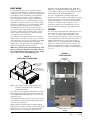
The IPBDF Plenum Box mounts on top of the unit and
has both vertically and horizontally adjustable louvers
on the front discharge grille.
VENT
OPTION
ACCESS
When used with a ducted supply, an ICX9 or ICX10
Cabinet Extension may be used to conceal the ductwork
above the unit to the ceiling. The ICX9 extends 20"
above the unit for a total height of 9'-6" for a floor
The I-TEC series heat pumps are designed for use with
free return (non-ducted) and either duct free with the
use of IPBDF Series Plenum Box (8" or 12") or a duct
supply air system.
12" X 20" X 1"
FILTERS
Manual2100-549L
Page
17 of 59
CONDENSATE DRAIN
WITH COMMERCIAL ROOM VENTILATOR
There are two condensate drain connections from the
condenser drain pan (compressor area). These are
visible from the rear of the unit. Factory installed
tubing connects the two drains at a tee connection and
then a single drain hose with a barbed hose connector
carries the condensate to the draining option of your
choice. Enough tubing is provided to reach all drain
options and can be cut down in length.
1. Open hinged front doors.
2. Disconnect unit power to eliminate shock hazard.
3. Remove front cover/door of CRV vent package. (Can
leave filter access panels in place.)
4. Unplug wires coming in on left side from upper unit
section.
5. Unplug two wire harness from front (intake) blower.
6. Remove two (2) screws securing front (intake) blower
and slide blower out of unit.
7. Remove four (4) screws that retain the partition
behind/beneath intake blower removed in Step #6.
8. Rear drain access panels are now visible on both
right-hand and left-hand sides in rear of box.
The unit is shipped from the factory with the drain line
on the left-hand side as you look at the rear of the unit.
The tubing can be removed from the drain connections
and flipped for a right-hand drain. See Figure 10.
The drain can be routed directly through the floor or
through the wall. There are also two optional drain
locations in the lower rear back panel. See Figure 8.
The I-TEC design does not require a trap in the
condensate disposal tubing. Check your local codes to
see if a “P” trap is required.
For a stand pipe floor drain or through the wall, there is
adequate hose length to reach anything located behind
the unit. The lower rear portion of the cabinet is recessed
approximately 4 inches allowing room for a “P” trap to
be installed with the cabinet flush with the wall. Keep in
mind, the drain line must be able to be removed from the
unit if necessary to remove the unit from the wall.
Access plates are located on the rear of the unit for
servicing the drain trap. See Figure 10. If the drain
line is to be routed through an unconditioned space, it
must be protected from freezing.
The condensate drain line can also be routed back
into the unit through either the right-hand or left-hand
optional drain locations on the rear of the unit. The
hole is covered by insulation on the inside of the unit
and will have to be cut away. Located inside the unit,
about 12 inches in from the front on both the left and
right side are drain holes in the bottom of the base.
These holes are covered with insulation and are not
visible. They are located very close to the side panels
and can be found by pressing down on the insulation.
Cut insulation away to expose the hole. A drain trap
can now be installed inside of the cabinet, and the
drain hose routed directly through the floor.
Once the I-TEC is installed, the rear drains exiting the
condenser section can be easily serviced with removal
of the pre-painted metal sides (lift-off doors, remove
four [4] screws to remove side).
WITH ENERGY RECOVERY VENTILATOR
To access the rear drain access panels of this section:
1. Open hinged front doors.
2. Disconnect unit power to eliminate shock hazard.
3. Remove front cover/door of ERV vent package. (Can
leave filter access panels in place.)
4. Unplug wires coming in on left side from upper unit
section.
5. Unplug heat recovery cassette on the side you wish to
access, and slide cassette out the front of the unit.
6. Remove two (2) screws securing partition on
outboard side of cassette and remove.
7. Rear drain access panels are now visible on both right-hand and left-hand sides in rear of box.
FIGURE 10 – DRAIN LOCATIONS
(2) Unit Drains
Drain Access
Locations
8"
3
38"
If side access is not available, the drain lines and trap
can be serviced by removing either one of the drain
access panels on the rear of the unit (in the ventilation
package area.) See Figure 10.
(2)OPTIONAL
DRAIN HOLES
3
38"
(2) Optional
Unit Drain
Entrances
WALL
7 3/16"
16 1/2"
WITH NO VENT OPTION
To access the drain access panels in the rear of this
section, simply remove the front door/cover from the
box, and the plates are located in the rear of the box.
Manual2100-549L
Page
18 of 59
18 3/4"
OPTIONAL FLOOR
MOUNTING HOLES
35"
3
40 4 "
MIS-2960 B
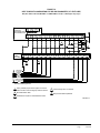
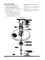
FIGURE 11A
UNIT MOUNTING
Use (12) Field Supplied Concrete
or Wood Screws to Secure Outer
Sleeve to Structure.
IMPORTANT!
Apply Caulk bead to
entire perimeter seam
between inner and
outer sleeve.
IMPORTANT!
Apply liberal amount
of caulk to back of
flange before installing.
REF.
A
REF.
B
Use (12) 3/4" Long
Self Tapping Screws
to Attach Inner Sleeve
to Unit Back
Use (6) 3/4" Long
Self Tapping Screws
to Attach Inner Sleeve
to Outer Sleeve
IMPORTANT!
Use care when inserting screws
to not damage gasketing material.
Doing so may compromise water
seal between unit and sleeve.
Pull Inner Frame
Out Until Flush
With Grille Mounting
Angle
REF.
E
REF.
C
REF.
Use (6) 3/4" Long
Screws to Attach
Exhaust Sleeve to
Unit Fan Shroud
(18) 5/16" - 3/4" SELF TAPPING A AND B
(6) 5/16" - 3/4" NON-TAPPING
(4) 5/16" - 1/2" NON-TAPPING
(4) 1-1/2" LONG SCREWS
REF.
C
REF.
D
REF.
E
Use (4) 1-1/2" Long
Screws to Attach
Louver Grille to
Outer Sleeve.
REF.
D
Use (4) 1/2" Long
Screws to Attach
frame to Exhaust
Sleeve
MIS-3014 A
Manual2100-549L
Page
19 of 59
FIGURE 11B
UNIT MOUNTING
Manual2100-549L
Page
20 of 59
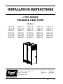
INSTALLATION INSTRUCTIONS
MOUNTING THE UNIT
WIRING – MAIN POWER
The wall sleeve is attached to the I-TEC unit from the
outside of the building. See Figures 11A & 11B. Refer
to wall sleeve Manual 2100-562 supplied with sleeve.
Refer to the unit rating plate and/or Table 2 for wire sizing
information and maximum fuse or circuit breaker size.
Each unit is marked with a “Minimum Circuit Ampacity”.
This means that the field wiring used must be sized to
carry that amount of current. Depending on the installed
KW of electric heat, there may be two field power circuits
required. If this is the case, the unit serial plate will so
indicate. All models are suitable only for connection with
copper wire. Each unit and/or wiring diagram will be
marked “Use Copper Conductors Only suitable for at least
75°C”. THESE INSTRUCTIONS MUST BE ADHERED
TO. Refer to the National Electrical Code (NEC) for
complete current carrying capacity data on the various
insulation grades of wiring material. All wiring must
conform to NEC and all local codes.
Following are the steps for attaching the I-TEC to the
wall sleeve.
1. Lift the unit into place making sure that it is
aligned side to side.
2. Push the unit back until the rear panel touches the
sleeve gasket.
3. This unit must be level from side to side and from
front to back. If adjustments are necessary, shim
up under the base rails with sheets of metal or any
substance not affected by moisture.
4. Attach the sleeve to the unit using the ten (10) ¾"
long self-tapping screws supplied with the sleeve.
5. The exhaust sleeve has three (3) ¾" long screw slots
in each side flange. Line these up with the screw
engagement holes in the fan panel. Attach using
six (6) ¾" long pointed sheet metal screws supplied
with the sleeve. Extend the sleeve out until it is
flush with the louver grill attachment angles.
6. Lock the sleeve in place using two (2) ½" long
pointed sheet metal screws on each side by
shooting through the slot into a pre-punched hole.
7. A bottom trim piece is shipped loose for
installation beneath the doors. Attach the trim
piece to the unit with screws provided.
8. The compressor is secured to the base with two (2)
bolts for shipping. Both bolts are identified with a
tag. Remove shipping bolts (Figure 5).
The electrical data lists fuse and wire sizes (75°C copper)
for all models, including the most commonly used heater
sizes. Also shown are the number of field power circuits
required for the various models with heaters.
The unit rating plate lists a “Maximum Time Delay
Relay" fuse or circuit breaker that is to be used with the
equipment. The correct size must be used for proper
circuit protection, and also to assure that there will be
no nuisance tripping due to the momentary high starting
current of the compressor motor.
See “START UP” section for information on three phase
scroll compressor start-ups.
The field wiring conduit connections are located on the
top right-hand corner of the unit with a wire raceway
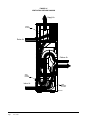
to feed the wires down to the circuit breaker(s). See
Figure 12.
FIGURE 12
COMPONENT LOCATION
ELECTRIC HEAT
INDOOR BLOWER
LOW VOLTAGE
WIRE RACEWAY
EVAPORATOR COIL
CONTROL PANEL
REFRIGERANT PORT
OUTDOOR FAN
CONDENSER COIL
COMPRESSOR
VENT OPTION
Manual2100-549L
Page
21 of 59
WIRING – LOW VOLTAGE WIRING
230/208V, 1 PHASE AND 3 PHASE EQUIPMENT
DUAL PRIMARY VOLTAGE TRANSFORMERS
All equipment leaves the factory wired on 240V tap.
For 208V operation, reconnect from 240V to 208V tap.
The acceptable operating voltage range for the 240 and
208V taps are as noted in Table 3.
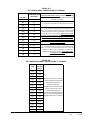
TABLE 3 – OPERATING VOLTAGE RANGE
TAP
RANGE
240V
253 – 216
208V
220 – 187
NOTE: The voltage should be measured at the field
power connection point in the unit and while the unit
is operating at full load (maximum amperage operating
condition).
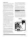
8403-067
(CDT-2W40-LCD-RLY)
CS9B-THO
CS9B-THOC
CS9BE-THO
CS9BE-THOC
“A” terminal is the ventilation input. This terminal
energizes any factory installed ventilation option.
“W3” terminal is second stage electric heat. When
“W3” terminal is energized, it locks out compressor
operation to limit discharge air temperature and
required branch circuit ampacity.
“D” terminal is the dehumidification mode (on models
so equipped).
Predominant Features
3 Stage Cool; 3 Stage Heat
Programmable/Non-Programmable Electronic
HP or Conventional
Auto or Manual changeover
Fan Only
Energize G
Cooling Part Load
Energize G, Y1
Cooling Full Load
Energize G, Y1, Y2
HP Heating Part Load
Energize G, Y1, B/W1
HP Heating Full Load
Energize G, Y1, Y2, B/W1
HP Heating Full Load + Electric Heat
(up to 10KW)
Energize G, Y1, Y2, B/W1, W2
Heating with Bank #1 Electric Heat Only
Energize G, W2
Emergency Heat (Heat pump operation
is negated for this condition)
Energize G, W2, W3
Ventilation
Energize A
Dehumidification *
* Models w/Dehumidification Only
Energize G, D
TABLE 4 – WALL THERMOSTATS
8403-060
(1120-445)
“W2” terminal is first stage electric heat (if equipped).
First stage electric heat can be operated simultaneously
with the heat pump operating.
NOTE: For total and proper control using DDC, a
minimum of 9 controlled outputs are needed when
above 10KW Electric Heat is employed with ventilation,
a total of 8 controlled outputs with below 10KW
Electric Heat with Ventilation, 7 controlled outputs
below 10KW Electric Heat with no ventilation, 7
controlled outputs with no Electric Heat, but with
ventilation, and 6 controlled outputs with no electric
heat and no ventilation. If Dehumidification Model &
Vent, 10 controlled outputs are needed when above
10KW Electric Heat is employed with ventilation.
The standard unit includes a remote thermostat
connection terminal strip. See Figures 13 through 19
for connection diagrams. Compatible thermostats are
listed in Table 4.
Thermostat
condensate overflow trip by the electronic heat pump
control. This is a 24 VAC output.
Carbon Dioxide Sensor with LCD for
Sensor Readings
3 Stage Heat, 3 Stage Cool, Prog/NonProg, HP or Conv,
Auto or Manual Changeover, Humidity Sensor w/
dehumidification, Motion Sensor w/ Intelligent Learning
Control, BACnet-compatible
3 Stage Heat, 3 Stage Cool, Prog/NonProg, HP or Conv,
Auto or Manual Changeover, Humidity Sensor w/
dehumidification, CO2 Sensor, Motion Sensor w/ Intelligent
Learning Control, BACnet-compatible
3 Stage Heat, 3 Stage Cool, Prog/NonProg, HP or Conv,
Auto or Manual Changeover, Humidity Sensor w/
dehumidification, Motion Sensor, Intelligent Learning Control,
BACnet-compatible, Ethernet-compatible
3 Stage Heat, 3 Stage Cool, Prog/NonProg, HP or Conv,
Auto or Manual Changeover, Humidity Sensor w/
dehumidification, CO2 Sensor, Motion Sensor w/ Intelligent
Learning Control, BACnet-compatible, Ethernet-compatible
LOW VOLTAGE CONNECTIONS
These units use a grounded 24 volt AC low voltage
circuit.
“G” terminal is the fan input.
“Y1” terminal is the compressor part load input.
“Y2” terminal is the compressor full load input.
“B/W1” terminal is the reversing valve input.
The reversing valve must be energized for heating mode.
“R” terminal is 24 VAC hot.
“C” terminal is 24 VAC grounded.
“L” terminal is compressor lockout output. This
terminal is activated on a high or low pressure trip and
Manual2100-549L
Page
22 of 59
LOW VOLTAGE CONNECTIONS FOR DDC CONTROL
GENERAL
This unit is equipped with a variable speed ECM motor.
The motor is designed to maintain rated airflow up to
the maximum static allowed. It is important that the
blower motor plugs are not plugged in or unplugged
while the power is on. Failure to remove power prior
to unplugging or plugging in the motor could result in
motor failure.
CAUTION
Do not plug in or unplug blower motor
connectors while the power is on. Failure to do
so may result in motor failure.
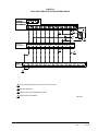
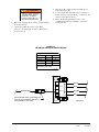
FIGURE 13
BASIC HEAT PUMP WITH NO VENTILATION PACKAGE
Completestat
Model #CS9B-THO or
Model #CS9BE-THO
SC
SC
SC
24V
COM
G
Y1
Y2
O/B
W2
L
W1/E
A
GND
D
Yellow
3
2
Blue
Orange
White
Red
Thermostat
Bard #8403-060
R
C
G
Y1
Y2
O/B
W2
L
W1/E
A
4
YO/D
2
3
Low
Voltage
Term. Strip
R
RT
C
G
Y1
Y2
B/W1
W2
W3
L
A
D
6
3
4
1
1
Factory installed jumper. Remove jumper and connect to N.C fire alarm
2 Not needed below 15KW
3
Additional wire required for dehumidification models
4
Relay Provided with Completestat
MIS-3016 A
Manual2100-549L
Page
23 of 59
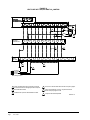
FIGURE 14
HEAT PUMP WITH CRV, WITHOUT CO2 CONTROL
SC
SC
SC
24V
COM
G
Completestat
Model #CS9B-THO or
Model #CS9BE-THO
Y1
Y2
O/B
W2
L
W1/E
A
GND
D
Yellow
3
Orange
2
Blue
White
6
Red
Thermostat
Bard #8403-060
R
C
G
Y1
Y2
O/B
W2
W1/E
L
A
YO/D
2
Low
Voltage
Term. Strip
R
RT
C
G
Y1
Y2
W2
B/W1
1
W3
L
3
A
D
6
4
3
5
4
RED/WHITE
BLACK/WHITE
ORANGE
BROWN/WHITE
CRV Wiring Harness
1 Factory installed jumper. Remove jumper and connect
to N.C fire alarm circuit if emergency shutdown required.
4
Connect to "G" terminal when thermostat has "Occupancy Signal".
2
Not needed below 15KW.
5
Install a jumper between "G" and "A" only when thermostat
without "Occupancy Signal" is used.
3
Additional wire required for dehumidification models.
Manual2100-549L
Page
24 of 59
6
Relay Provided with Completestat
MIS-3017 A
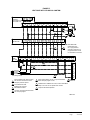
FIGURE 15
HEAT PUMP WITH CRV AND CO2 CONTROL
SC
SC
SC
24V
COM
G
Completestat
Model #CS9B-THO or
Model #CS9BE-THO
Y1
Y2
O/B
W2
L
W1/E
A
D
GND
Yellow
3
2
Blue
Orange
White
7
Red
Thermostat
Bard #8403-060
R
C
G
Y1
Y2
O/B
W2
W1/E
L
A
YO/D
NOTE:Bard 8403-060
thermostat must
be in programmed
3
operation mode and in
programmed fan mode
for ventilation to function.
2
Low
Voltage
Term. Strip
R
RT
C
G
Y1
Y2
W2
B/W1
W3
L
A
D
6
3
5
1
2
4
1
RED/WHITE
BLACK/WHITE
ORANGE
BROWN/WHITE
5
6
CRV Wiring Harness
1
Factory installed jumper. Remove jumper
and connect to N.C fire alarm circuit if
emergency shutdown required.
2
Not needed below 15KW.
3
Additional wire required for
dehumidification models.
4
Connect to "G" terminal when thermostat
has "Occupancy Signal".
4
6
6 CO2 Control
Bard #8403-067
5
Install a jumper between "G" and "A" only when thermostat
without "Occupancy Signal" is used.
6
If CS9B-THOC or CS9BE-THOC is used, connect "Brown/White"
directly to "A" and do not use seperate CO2 controller.
7
Relay Provided with Completestat
MIS-3018 A
Manual2100-549L
Page
25 of 59
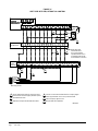
FIGURE 16
HEAT PUMP WITH ERV, WITHOUT CO2 CONTROL
SC
SC
SC
24V
COM
G
Completestat
Model #CS9B-THO or
Model #CS9BE-THO
Y1
Y2
O/B
W2
L
W1/E
A
GND
D
Yellow
3
2
Blue
Orange
White
Red
6
Thermostat
Bard #8403-060
R
C
G
Y1
Y2
O/B
W2
W1/E
L
A
YO/D
NOTE:Bard 8403-060
thermostat must
3
be in programmed
operation mode and in
programmed fan mode
for ventilation to function.
2
Low
Voltage
Term. Strip
R
RT
C
G
Y1
Y2
W2
B/W1
1
W3
L
A
D
6
4
3
5
4
RED/WHITE
BLACK/WHITE
ORANGE
BROWN/WHITE
PINK
PURPLE
ERV Wiring Harness
1 Factory installed jumper. Remove jumper and connect
to N.C fire alarm circuit if emergency shutdown required.
4
Connect to "G" terminal when thermostat has "Occupancy Signal".
2
Not needed below 15KW.
5
Install a jumper between "G" and "A" only when thermostat
without "Occupancy Signal" is used.
3
Additional wire required for dehumidification models.
6 Relay Provided with Completestat
MIS-3019 A
Manual2100-549L
Page
26 of 59
FIGURE 17
HEAT PUMP WITH ERV AND CO2 CONTROL (ON/OFF CYCLING)
Completestat
Model #CS9B-THO or
Model #CS9BE-THO
SC
SC
SC
24V
COM
G
Y1
Y2
O/B
W2
L
W1/E
A
D
GND
Yellow
3
2
Blue
Orange
White
7
Red
Thermostat
Bard #8403-060
R
C
G
Y1
Y2
O/B
W2
L
W1/E
A
YO/D
NOTE:Bard 8403-060
thermostat must
3
be in programmed
operation mode and in
programmed fan mode
for ventilation to function.
2
Low
Voltage
Term. Strip
R
RT
C
G
Y1
Y2
W2
B/W1
W3
L
A
5
1
6
Not needed below 15KW.
3
Additional wire required for dehumidification models.
4
Connect to "G" terminal when thermostat has
"Occupancy Signal".
4
5
6
ERV Wiring Harness
2
3
1
RED/WHITE
BLACK/WHITE
ORANGE
BROWN/WHITE
PINK
PURPLE
Factory installed jumper. Remove jumper and connect
to N.C fire alarm circuit if emergency shutdown required.
6
2
4
1
D
5
6 CO2 Control
Bard #8403-067
Install a jumper between "G" and "A" only when thermostat
without "Occupancy Signal" is used.
6
If CS9B-THOC or CS9BE-THOC is used, connect "Brown/White"
directly to "A" and do not use seperate CO2 controller.
7
Relay Provided with Completestat
MIS-3020 A
Manual2100-549L
Page
27 of 59
FIGURE 18
HEAT PUMP WITH ERV AND CO2 CONTROL (FULLY MODULATING)
Completestat
Model #CS9B-THO or
Model #CS9BE-THO
SC
SC
SC
24V
COM
G
Y1
Y2
O/B
W2
L
W1/E
A
D
GND
Yellow
3
2
Blue
Orange
White
6
Red
Thermostat
Bard #8403-060
R
C
G
Y1
Y2
O/B
W2
L
W1/E
A
YO/D
NOTE:Bard 8403-060
thermostat must
be in programmed
3
operation mode and in
programmed fan mode
for ventilation to function.
2
Low
Voltage
Term. Strip
R
RT
C
G
Y1
Y2
W2
B/W1
W3
L
A
D
6
3
4
5
1
2
4
1
RED/WHITE
BLACK/WHITE
ORANGE
BROWN/WHITE
PINK
PURPLE
3
CO2 Control
Bard #8403-067
ERV Wiring Harness
1 Factory installed jumper. Remove jumper and connect
to N.C fire alarm circuit if emergency shutdown required.
4
Connect to "G" terminal when thermostat has "Occupancy Signal".
2
Not needed below 15KW.
5
Install a jumper between "G" and "A" only when thermostat
without "Occupancy Signal" is used.
3
Additional wire required for dehumidification models.
6
Relay Provided with Completestat
Manual2100-549L
Page
28 of 59
MIS-3021 B
FIGURE 19
HEAT PUMP WITH COMBINATION CRV AND DB ECONOMIZER (“N” VENT CODE)
Only Recommend Bard CS9B-THOC or CS9BE-THOC as Require 3 Heating/Cooling Stages
Completestat
Model #CS9B-THOC or
Model #CS9BE-THOC
SC
SC
SC
24V
COM
G
Y0
Y1
Y2
O/B
W2
W1/E
L
A
GND
D
3
2
Yellow
Orange
Blue
White
5
Red
Low
Voltage
Term. Strip
R
RT
1
C
G
6
7
8
B/W1
W2
W3
L
A
D
Y1
Y2
4
RED/WHITE
BLACK/WHITE
ORANGE
GRAY
YELLOW
PURPLE
BROWN/WHITE
PURPLE/WHITE
YELLOW/BLACK
BLUE
CRV/ECON Wiring Harness
1
Factory installed jumper. Remove jumper and connect
to N.C fire alarm circuit if emergency shutdown required.
4
Connect orange wire to "G" terminal
2
Not needed below 15KW.
5
Relay Provided with Completestat
3
Additional wire required for dehumidification models.
MIS-3270 A
Manual2100-549L
Page
29 of 59
START UP
THESE UNITS REQUIRE R-410A
REFRIGERANT AND POLYOL
ESTER OIL.
REMEMBER: When adding R-410A refrigerant, it
must come out of the charging cylinder/tank as a liquid
to avoid any fractionation, and to insure optimal system
performance. Refer to instructions for the cylinder that
is being utilized for proper method of liquid extraction.
GENERAL
1. Use separate service equipment to avoid cross
contamination of oil and refrigerants.
2. Use recovery equipment rated for R-410A
refrigerant.
3. Use manifold gauges rated for R-410A (800
psi/250 psi low).
WARNING
Failure to conform to these practices
could lead to injury or death.
4. R-410A is a binary blend of HFC-32 and HFC125.
5. R-410A is nearly azeotropic - similar to R-22 and
R-12. Although nearly azeotropic, charge with
liquid refrigerant.
SAFETY PRACTICES
6. R-410A operates at 40-70% higher pressure than
R-22, and systems designed for R-22 cannot
withstand this higher pressure.
2. Use gloves and safety glasses. Polyol Ester oils
can be irritating to the skin, and liquid refrigerant
will freeze the skin.
7. R-410A has an ozone depletion potential of zero,
but must be reclaimed due to its global warming
potential.
3. Never use air and R-410A to leak check; the
mixture may become flammable.
8. R-410A compressors use Polyol Ester oil.
9. Polyol Ester oil is hygroscopic; it will rapidly absorb
moisture and strongly hold this moisture in the oil.
10.A liquid line dryer must be used - even a deep
vacuum will not separate moisture from the oil.
11.Limit atmospheric exposure to 15 minutes.
12.If compressor removal is necessary, always plug
compressor immediately after removal. Purge with
small amount of nitrogen when inserting plugs.
TOPPING OFF SYSTEM CHARGE
If a leak has occurred in the system, Bard
Manufacturing recommends reclaiming, evacuating
(see criteria above), and charging to the nameplate
charge. However, if done correctly, topping off the
system charge can be done without problems.
With R-410A, there are no significant changes in the
refrigerant composition during multiple leaks and
recharges. R-410A refrigerant is close to being an
azeotropic blend (it behaves like a pure compound
or single component refrigerant). The remaining
refrigerant charge, in the system, may be used after
leaks have occurred and then “top-off” the charge by
utilizing the charging charts on the inner control panel
cover as a guideline.
Manual2100-549L
Page
30 of 59
1. Never mix R-410A with other refrigerants.
4. Do not inhale R-410A – the vapor attacks
the nervous system, creating dizziness, loss
of coordination and slurred speech. Cardiac
irregularities, unconsciousness and ultimate death
can result from breathing this concentration.
5. Do not burn R-410A. This decomposition
produces hazardous vapors. Evacuate the area if
exposed.
6. Use only cylinders rated DOT4BA/4BW 400.
7. Never fill cylinders over 80% of total capacity.
8. Store cylinders in a cool area, out of direct
sunlight.
9. Never heat cylinders above 125°F.
10.Never trap liquid R-410A in manifold sets, gauge
lines or cylinders. R-410A expands significantly
at warmer temperatures. Once a cylinder or line is
full of liquid, any further rise in temperature will
cause it to burst.
DESCRIPTION OF STANDARD
EQUIPMENT
Solid State Electronic Heat Pump Control
Provides efficient 30, 60 or 90-minute defrost cycle.
A thermistor sensor and speed up terminal for service
along with a 8-minute defrost override are standard on
the electronic heat pump control. By default, the I-TEC
are factory shipped on the 90-minute defrost cycle.
High/Low Pressure Switch
Provides refrigerant circuit high pressure and loss
of charge protection. Includes lockout circuit built
into heat pump control that is resettable from room
thermostat.
Five Minute Compressor Time Delay
Provides short cycle protection for the compressor
which extends compressor life. Built into the electronic
heat pump control as standard.
Condensate Overflow
Senses and provides system shut down if draining issue
causes water level to rise in the lower drain pan.
Low Ambient Control
The low ambient control permits cooling operation
down to 0°F outdoor ambient.
IMPORTANT INSTALLER NOTE
For improved start-up performance, wash the indoor
coil with a dishwasher detergent.
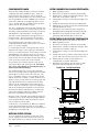
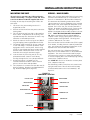
PHASE MONITOR
All units with three phase scroll compressors are
equipped with a 3 phase line monitor to prevent
compressor damage due to phase reversal.
The phase monitor in this unit is equipped with two
LEDs. If the Y signal is present at the phase monitor
and phases are correct the green LED will light and the
compressor contactor is allowed to energize.
If phases are reversed, the red fault LED will be lit and
compressor operation is inhibited.
If a fault condition occurs, reverse two of the supply
leads to the unit. Do not reverse any of the unit factory
wires as damage may occur.
THREE PHASE SCROLL COMPRESSOR
START UP INFORMATION
Scroll compressors, like several other types of
compressors, will only compress in one rotational
direction. Direction of rotation is not an issue with
single phase compressors since they will always start
and run in the proper direction.
However, three phase compressors will rotate in either
direction depending upon phasing of the power.
Since there is a 50-50 chance of connecting power
in such a way as to cause rotation in the reverse
direction, verification of proper rotation must be made.
Verification of proper rotation direction is made by
observing that suction pressure drops and discharge
pressure rises when the compressor is energized.
Reverse rotation also results in an elevated sound level
over that with correct rotation, as well as, substantially
reduced current draw compared to tabulated values.
Verification of proper rotation must be made at the time
the equipment is put into service. If improper rotation
is corrected at this time there will be no negative
impact on the durability of the compressor. However,
reverse operation for even one hour may have a negative
impact on the bearing due to oil pump out.
All three phase scroll compressors used in the I-TEC
series are wired identically internally. As a result, once
the correct phasing is determined for a specific system
or installation, connecting properly phased power
leads to the same Fusite terminal should maintain
proper rotation direction. The direction of rotation of
the motor may be changed by reversing any two line
connections to the unit.
SERVICE HINTS
1. Caution user to maintain clean air filters at all
times and also not to needlessly close off supply
air registers. This may reduce airflow through the
system, which shortens equipment service life as
well as increasing operating costs and noise levels.
2. Switching to heating cycle at 75°F or higher outside
temperature may cause a nuisance trip of the
remote reset high pressure switch. Turn thermostat
off, then on to reset the high pressure switch.
3. The heat pump wall thermostats perform multiple
functions. Be sure that all function switches are
correctly set for the desired operating mode before
trying to diagnose any reported service problems.
4. Check all power fuses or circuit breakers to be sure
they are the correct rating.
5. Periodic cleaning of the outdoor coils to permit full
and unrestricted airflow circulation is essential.
6.Annual maintenance is required to make sure that
all of the systems are functioning properly.
a. Check to make sure that the drains are not obstructed in any way.
b. Remove any debris in the condenser section of the unit.
c. Inspect and wash outdoor coils as necessary.
7. All motors are sealed and require no oiling.
Manual2100-549L
Page
31 of 59
SEQUENCE OF OPERATION
PRESSURE SERVICE PORTS
COOLING PART LOAD – Circuit R-Y1 makes at
thermostat pulling in compressor contactor, starting
the compressor and outdoor motor. The G (indoor
motor) circuit is automatically completed on any call
for cooling operation or can be energized by manual fan
switch on subbase for constant air circulation.
High and low pressure service ports are installed on
all units so that the system operating pressures can be
observed. Pressure tables can be found later in the
manual covering all models. It is imperative to match
the correct pressure table to the unit by model number.
Upper and lower service doors must be attached to
obtain proper reading.
COOLING FULL LOAD – Circuit R-Y1 & Y2 makes at
the thermostat energizing the 2nd stage solenoid in the
compressor. The default position of the compressor
staging solenoid is non-energized. The compressor will
run at low capacity until this solenoid is energized.
HEATING STAGE 1 – A 24V solenoid coil on reversing
valve controls heating cycle operation. Two thermostat
options, one allowing “Auto” changeover from cycle to
cycle and the other constantly energizing solenoid coil
during heating season and thus eliminating pressure
equalization noise except during defrost, are to be
used. On “Auto” option a circuit is completed from
R-B and R-Y1 on each heating “on” cycle, energizing
reversing valve solenoid and pulling in compressor
contactor starting compressor and outdoor motor. R-G
also make starting indoor blower motor. Heat pump
heating cycle now in operation. The second option has
no “Auto” changeover position, but instead energizes
the reversing valve solenoid constantly whenever the
system switch on subbase is placed in “Heat” position,
the “B” terminal being constantly energized from
R. A thermostat demand for Stage 1 heat completes
R-Y1 circuit, pulling in compressor contactor starting
compressor and outdoor motor. R-G also make starting
indoor blower motor.
HEATING STAGE 2 – Circuit R-Y1 & Y2 makes at the
thermostat energizing the 2nd stage solenoid in the
compressor.
Manual2100-549L
Page
32 of 59
LOWERING OUTDOOR FAN SPEED FOR
SOUND
Supplied in the Literature Assembly is a Fan Control
Resistor Assembly that can be installed to lower the fan
speed for reduced sound performance. This Resistor
Assembly is to be installed in series with the Outdoor
Fan Control Thermistor to change the temperature
curve that the fan logic control sees.
It is anticipated that you will see a 2-3% drop in
system capacity and efficiency when this resistor is
installed.
To install the Resistor Assembly:
1. Locate Fan Control Resistor Assembly in Literature
Packet hanging on right inside door of unit.
2. Throw main power disconnect to the “OFF”
position to eliminate risk of injury or death due to
electrical shock.
3. Remove four (4) screws that retain the control
panel cover to the unit.
4. Locate Fan Logic Control Board.
5. Locate one of the red leads of the Fan Control
Thermistor where it attaches to the Fan Logic
Control and remove it.
6. Install resistor in-line with the thermistor lead
removed in Step #5, and then connect back onto
the Fan Logic Control Board.
DEFROST CYCLE
The defrost cycle is controlled by temperature and time
on the solid state heat pump control. See Figure 20.
When the outdoor temperature is in the lower
40°F temperature range or colder, the outdoor coil
temperature is 32°F or below. This coil temperature
is sensed by the coil temperature sensor mounted near
the bottom of the outdoor coil. Once coil temperature
reaches 30°F or below, the coil temperature sensor
sends a signal to the control logic of the heat pump
control and the defrost timer will start accumulating
run time.
After 30, 60 or 90 minutes of heat pump operation at
30°F or below, the heat pump control will place the
system in the defrost mode. Factory default setting is
90 minutes.
During the defrost mode, the refrigerant cycle switches
back to the cooling cycle, the outdoor motor stops,
electric heaters are energized, and hot gas passing
through the outdoor coil melts any accumulated frost.
When the temperature rises to approximately 57°F, the
coil temperature sensor will send a signal to the heat
pump control which will return the system to heating
operations automatically.
If some abnormal or temporary condition such as a high
wind causes the heat pump to have a prolonged defrost
cycle, the heat pump control will restore the system to
heating operation automatically after 8 minutes.
The heat pump defrost control board has an option of
30, 60 or 90-minute setting. All models are shipped
from the factory on the 90-minute pin. If special
circumstances require a change to another time,
remove the wire from the 90-minute terminal and
reconnect to the desired terminal.
The manufacturer’s recommendation is for 90-minute
defrost cycles. Refer to Figure 20.
There is an initiate defrost jumper (sen jump) on the
control that can be used at any outdoor ambient during
the heating cycle to simulate a 0° coil temperature.
This can be used to check defrost operation of the unit
without waiting for the outdoor ambient to fall into the
defrost region.
By placing a jumper across the SEN JMP terminals
(a ¼ inch QC terminal works best) the defrost sensor
mounted on the outdoor coil is shunted out & will
activate the timing circuit. This permits the defrost
cycle to be checked out in warmer weather conditions
without the outdoor temperature having to fall into the
defrost region.
In order to terminate the defrost test the SEN JMP
jumper must be removed. If left in place too long, the
compressor could stop due to the high pressure control
opening because of high pressure condition created
by operating in the cooling mode with outdoor fan off.
Pressure will rise fairly fast as there is likely no actual
frost on the outdoor coil in this artificial test condition.
There is also a 5-minute compressor time delay function
built into the HPC. This is to protect the compressor
from short cycling conditions. The board’s LED will have
a fast blink rate when in the compressor time delay. In
some instances, it is helpful to the service technician to
override or speed up this timing period, and shorting out
the SPEEDUP terminals for a few seconds can do this.
FIGURE 20
DEFROST CYCLE
LOW PRESSURE BYPASS TIMER SWITCH
*(FACTORY SETTING 120 SECONDS)
SW SW
1
2 TIME (SEC)
OFF OFF
30
ON OFF
60
120*
OFF ON
ON ON
180
OFF
There is a cycle speed up jumper on the control. This
can be used for testing purposes to reduce the time
between defrost cycle operation without waiting for
time to elapse.
ON
Use a small screwdriver or other metallic object, or
another ¼ inch QC, to short between the SPEEDUP
terminals to accelerate the HPC timer and initiate
defrost.
Be careful not to touch any other terminals with the
instrument used to short the SPEEDUP terminals.
It may take up to 15 seconds with the SPEEDUP
terminals shorted for the speedup to be completed and
the defrost cycle to start.
As soon as the defrost cycle kicks in remove the
shorting instrument from the SPEEDUP terminals.
Otherwise the timing will remain accelerated and
run through the 1-minute minimum defrost length
sequence in a matter of seconds and will automatically
terminate the defrost sequence.
ACCUMULATED DEFROST TIME TIMER
(FACTORY
SETTING
60 MIN.)
(FACTORY
SETTING
90 MIN.)
MIS-2668 A
Manual2100-549L
Page
33 of 59
I-TEC COMMERCIAL ROOM
VENTILATOR SYSTEM
GENERAL DESCRIPTION
The I-TEC Commercial Room Ventilator (CRV) is
designed to be used with all Bard I-TEC models. The
only intent of this device is to provide the required
ventilation by delivering fresh air to meet I.A.Q. (Indoor
Air Quality) requirements. In the installed application,
this system also includes exhaust provisions which
are balanced with the intake air to maintain building
pressurization requirements of ASHRAE 62.1
Standard.
Ventilation is accomplished with (2) blower/
motor assemblies for maximum ventilation at low
sound levels. The intake and exhaust blowers are
programmed independently and are balanced to
maintain a slight positive pressurization in accordance
to ASHRAE 62.1 Standard.
The I-TEC CRV is also provided with filters to reduce
the required service needed and to further improve
the I.A.Q. The exhaust air blowers are protected
by disposable filters, and the intake air blowers are
protected by washable filters. Both are accessible
without the need for tools.
CONTROL WIRING
The I-TEC CRV comes wired from the factory set to
375 CFM of ventilation. Care must be taken when
deciding how to control the operation of the ventilator.
When designing the control circuit for the ventilator,
the following requirements must be met.
1. The indoor blower must be run whenever the I-TEC
CRV is run.
2. Select and configure the correct CFM ventilation
level that the I-TEC CRV needs to operate and
configure the system to this level following later
instructions within this section. Over ventilating
serves no useful purpose and significantly affects
the overall efficiency of the heat pump system.
System operating costs would also increase.
3. Run the I-TEC CRV only during periods when
the conditioned space is occupied. Running the
ventilation during unoccupied periods wastes
energy, decreases the expected life of the CRV,
and can result in large moisture buildup in the
structure. Running the CRV when the structure
is unoccupied allows moisture to build up in the
structure because there is little or no cooling load.
Thus, the air conditioner is not running enough to
remove the excess moisture being brought in. Use
a control system that in some way can control the
system based upon occupancy.
Manual2100-549L
Page
34 of 59
Operating the I-TEC CRV during unoccupied periods can
result in a build up of excess moisture in the structure.
RECOMMENDED CONTROL
SEQUENCES
Several possible scenarios are listed below:
1. Use a programmable electronic thermostat with
auxiliary terminal to control the CRV based on
daily programmed occupance periods. Bard
markets and recommends Bard Part #8403-060
programmable electronic thermostat.
2. Use Bard CompleteStat™ that incorporates
temperature, humidity and occupancy control
with learning capability into a single device. No
programming required.
3. Use a DDC control system to control the CRV
based upon a room occupancy schedule to control
the CRV.
4. Tie the operation of the CRV into the light switch.
The lights in a room are usually on only when
occupied.
5. Use a manual timer that the occupants turn to
energize the CRV for a specific number of hours.
6. Use a programmable mechanical timer to energize
the CRV and indoor blower during occupied periods
of the day.
NOTE: The ventilation package comes with a blower
interlock function, but is disabled when it is shipped
from the factory in case you do not utilize a thermostat
with an occupancy output, or a occupancy sensor
and must tie “A” terminal to “G” terminal to drive the
ventilation package. If you do have a thermostat or
control that does drive occupancy output, you will need
to remove the tape from the orange wire located in the
low voltage terminal box, and connect it to the “G”
terminal to activate this function. (See Figures 13-19.)
SETTING THE VENTILATION CFM
LEVELS
The I-TEC CRV has four pre-set levels of ventilation
CFM available. These are 300, 375, 450 and 525
CFM of ventilation air. The I-TEC CRV is shipped from
the factory set on the 375 CFM ventilation level. To
change between these four different levels of provided
ventilation CFM, first refer to Figure 21 to look up the
corresponding CFM needed for the intake and exhaust
blowers to meet the design criteria and determine
which “speed/wire color” is needed. Then, perform the
following steps.
REMOVE TO DISASSEMBLE, DO NOT
OVERTIGHTEN BOLTS WHEN REPLACING
IMP
level needed in accordance
Suction Discharge
(Low)
(High)
UNIT TIE PLATE
Front Trim
Piece
7961-754-2
corresponding
CFM
3 PHASE LINE MONITOR
CODES
HP. BOARD TROUBLESHOOTING CODES
with Figure 21.
DESCRIPTION
Open front
swinging
doors of main unit (byCODE
popping
DESCRIPTION
CODE
GREEN PHASES CORRECT, Y SIGNAL
SLOW BLINK NORMAL OPERATION
front door
latches).
LIGHT PRESENT
FAST
BLINK COMPRESSOR TIME DELAY
1 BLINK
PRESS. SWITCH
1.370
PHASES INCORRECT, REVERSE
Throw main
powerLOdisconnect
toFAILURE
the “OFF”
2 BLINKS
HI PR. SW./WATER SNSR. FAIL. RED
2 UNIT SUPPLY LEADS. DO NOT
position 3toBLINKS
eliminate
risk MODE
of injury
due to
DEFROST
ACTIVEor death
LIGHT
MODIFY FACTORY WIRING. DOING
4
BLINKS
HI
PRESS.
HARD
LOCKOUT
SO MAY RESULT IN UNIT DAMAGE.
electrical shock.
7961-754-4
7961-754-5
UNIT TIE PLATE
7961-754-10
R-410A
7961-754-5
REMOVE TO DISASSEMBLE, DO NOT
OVERTIGHTEN BOLTS WHEN REPLACING
7961-754-7
7961-754-3
VENT POWER CONNECTION
UNPLUG AND REMOVE WIRE CLAMPS
7961-754
TO DISASSEMBLE UNIT 7961-754-6
8.500
FIGURE 21
CRV MOTOR SPEED/CFM CONFIGURATION
COLORS: ROSE
BRIGHT YELLOW
DARK ORANGE
WHITESPEEDS
BACKGROUND
VENT OPTION INTAKE/EXHAUST
WIRE COLOR
SPEEDDIECUT
NOM.
CFM
FORM:
SHEET
BLACK
525
HI
MATERIAL: OUTDOOR VINYL, SUPPLIER MUST BE CSA
BLUE
450 FOR ACCEPTABLE ADHESIVE
MED-HIAPPROVED
ORANGE
375 LISTING.
MED-LONAMEPLATE
300
LO
RED
PRINTING: BLACK
TO CHANGE SPEEDS, MOVE BROWN
INDOOR/OUTDOOR
END USE:
WIRE WITH WHITE
TRACE.
7961-755-2
HI
MED. HI
BROWN/WHITE
MED. LO
LO
7961-7554
Move brown/white wire to corresponding motor
speed for required ventilation CFM. Factory
setting is Medium Lo (375 CFM).
5.500
HAZARD OF ELECTRICAL SHOCK.
HAZARD OF ELECTRICAL SHOCK.
4. CAN
Locate
“Brown Wire
with White
that has a
ELECTRICAL
SHOCK Trace”
CAN RESULT
ELECTRICAL SHOCK
RESULT
IN SERIOUS
the endINJURY
whereORitDEATH.
connects to the
IN SERIOUS INJURY ORblack
DEATH.terminal on
DISCONNECT
THE REMOTE
DISCONNECT THE REMOTE
terminal strip (See
Figure 21).
ELECTRIC POWER SUPPLY OR
ELECTRIC POWER SUPPLY OR
SUPPLIES
SERVICING.
5.SERVICING.
Move “Brown Wire
with BEFORE
White Trace”
to the
SUPPLIES BEFORE
Top Wall
Bracket
2.
3. Remove six (6) screws holding front CRV door in 7961-754-8
WARNING
place (See Figure! 22). WARNING
MOTOR SPEEDS
1.
HAZARD OF ELECTRICAL SHOCK.
ELECTRICAL SHOCK CAN RESULT
IN SERIOUS INJURY OR DEATH.
DISCONNECT THE REMOTE
ELECTRIC POWER SUPPLY OR
SUPPLIES BEFORE SERVICING.
!
EXPOSED MOVING PARTS.
DISCONNECT ALL ELECTRICAL
POWER BEFORE SERVICING.
FAILURE TO DO SO CAN RESULT
IN SEVERE INJURY OR AMPUTATION.
7961-754-2
1.370
WARNING
7961-754-2
!
7961-754-1
7961-754-1
EXPOSED MOVING PARTS.
DISCONNECT ALL ELECTRICAL
POWER BEFORE SERVICING.
FAILURE TO DO SO CAN RESULT
IN SEVERE INJURY OR AMPUTATION.
3 PHASE SCRO
REQUIRE PROP
TO INSTALLATIO
PROPER STAR
7961-754-1
EXPOSED MOVING PARTS.
DISCONNECT ALL ELECTRICAL
POWER BEFORE SERVICING.
FAILURE TO DO SO CAN RESULT
IN SEVERE INJURY OR AMPUTATION.
BLACK
BLUE
ORANGE
RED
MIS-3022 A
Manual2100-549L
Page
35 of 59
C
FIGURE 22
CRV SPEED CHANGE TERMINAL ACCESS
CRV INTAKE BLOWER
NOTE: CRV EXHAUST
BLOWER IS BEHIND
INTAKE BLOWER
REMOVE (5) SCREWS FROM
CRV DOOR TO ACCESS CRV
COMPONENTS
MIS-3023
BLOWER SPEED
CONTROL LOCATION
BLOWER
SPEED
CONTROL
BLOWER REMOVED
FOR CLARITY
Manual2100-549L
Page
36 of 59
I-TEC COMBINATION CRV AND
ECONOMIZER VENTILATION SYSTEM
DESCRIPTION
The I-TEC combination Commercial Room Ventilator
(CRV) and Dry Bulb Economizer is designed to be used
with all Bard I-TEC models. This ventilation package
and its control provides two (2) roles:
• It will provide the required ventilation by delivering
fresh air to meet I.A.Q. (Indoor Air Quality)
requirements through CRV portion of the device.
• It will provide up to 525 CFM of free outdoor
cooling CFM when the outdoor ambient
temperature is below the outdoor thermostat
setpoint.
Ventilation is accomplished with (2) blower/
motor assemblies for maximum ventilation at low
sound levels. The intake and exhaust blowers are
programmed independently and are balanced to
maintain a slight positive pressurization in accordance
to ASHRAE 62.1 Standard.
The Ventilation Package is also provided with filters
to reduce the required service needed and to further
improve the I.A.Q. The exhaust air blowers are
protected by disposable filters, and the intake air
blowers are protected by washable filters. Both are
accessible without the need for tools.
CONTROL WIRING
Refer to Low Voltage Connection (Figure 19).
Reference Figure 23 for Control Sequence of
Operation.
Operating the I-TEC CRV during unoccupied
periods can result in a build up of excess
moisture in the structure.
SETTING THE VENTILATION CFM
LEVELS
The I-TEC CRV has four (4) pre-set levels of ventilation
CFM available. These are 300, 375, 450 and 525
CFM of ventilation air. This ventilation package
is shipped from the factory set on the 375 CFM
ventilation level while the Economizer portion is set
on the 525 CFM ventilation level. To change between
these four different levels of provided ventilation CFM,
refer to Figure 24 to look up the corresponding CFM
needed for the intake and exhaust blowers to meet the
design criteria and determine which “speed/wire color”
is needed.
Perform the following steps:
1. Open front swinging doors of main unit (by popping
front door latches).
Open disconnect to shut all power OFF before
doing this! Failure to do so could result in
injury or death due to electrical shock.
2. Throw main power disconnect to the “OFF”
position to eliminate risk of injury or death due to
electrical shock.
3. Remove six (6) screws holding front CRV door in
place (see Figure 22).
4. For CRV blower speed, locate “Brown Wire with
White Trace” that has as black terminal on the end
where it connects to the terminal strip (see Figure
24).
5. Move the “Brown Wire with White Trace” to the
corresponding CFM level needed in accordance
with Figure 24.
6. For Economizer Blower Speed, locate “Pink Wire”
that has a black terminal on the end where it
connects to the terminal strip (see Figure 24).
7. Move the “Pink” to the corresponding CFM level
needed in accordance with Figure 24.
Manual2100-549L
Page
37 of 59
I-TEC ECON. SEQUENCE OF
OPERATION
•
If outdoor temperature is below outdoor thermostat
setpoint
On call from CompleteStat for first stage cooling:
• “YO” thermostat signal powers vent blower motors
at Economizer Speed/Airflow (black – 525 CFM)
through NC contacts of Relay “R1” (“Dehum
Relay”).
On call from CompleteStat for first and second stage
cooling:
• “YO” thermostat signal powers vent blower motors
at Economizer Speed/Airflow (black – 525 CFM)
through NC contacts of Relay “R1” (“Dehum
Relay”).
• “Y1” thermostat signal powers “Y1” terminal on
unit low voltage terminal strip through NC contacts
of relay “R2” (“High Ambient Relay”).
On call from CompleteStat for first, second and third
stage cooling:
• “YO” thermostat signal powers vent blower motors
at Economizer Speed/Airflow (black – 525 CFM)
through NC contacts of Relay “R1” (“Dehum
Relay”).
• “Y1” thermostat signal powers “Y1” terminal on
unit low voltage terminal strip through NC contacts
of relay “R2” (“High Ambient Relay”).
If outdoor temperature is above outdoor thermostat
setpoint
On call from CompleteStat for first stage cooling:
• “YO” thermostat signal powers relay coil “R2”.
“R2” relay then closes NO contact between “R”
and “Y1” at low voltage terminal strip engaging
stage 1 mechanical cooling. NC contacts of relay
“R2” that connects thermostat “Y1” to “Y1” on
low voltage terminal strip is opened to eliminate
feedback.
On call from CompleteStat for first and second stage
cooling:
• “YO” thermostat signal powers relay coil “R2”. “R2”
relay then closes NO contact between “R” and
“Y1” at low voltage terminal strip engaging stage 1
mechanical cooling. NC contacts of relay “R2” that
connects thermostat “Y1” to “Y1” on low voltage
terminal strip is opened to eliminate feedback.
• “Y1” thermostat signal powers relay coil “R3”
through now closed relay contacts “R2” closing
contacts between “R” and “Y2” at low voltage
terminal strip.
• “Y2” thermostat signal will do nothing, as NC
contacts of relay “R2” are now opened to eliminate
any feedback to thermostat.
FIGURE 23 ECONOMIZER CONTROL CIRCUIT
THERMOSTAT
SIGNALS
UNIT LOW
VOLTAGE
TERMINAL
STRIP
Y2
8
6
R2
Dehumidification Mode
On call from CompleteStat for dehumidification:
• “D” thermostat signal powers relay coil “R1” (Dehum. Relay). “R1” relay, then opens NC
contact between “YO” and outdoor thermostat.
This will then negate any ECONOMIZER SPEED SIGNAL from energizing the ventilation package.
“Y1” & “Y2” thermostat signals will pass
through NC contacts of Relay “R2” (“High
Ambient Relay”) as relay coil “R2” will
be rendered inoperable by “R1” contacts
opening. Normal cooling calls can then still
apply to override Dehum. call.
3
Y2
COM
8
R
COM
R3
R2
R4
NO
5
NO
G
Y1
7
Y1
7
D
D
YO
6
7
R2
R2
“Y2” thermostat signal powers “Y2” terminal on
unit low voltage terminal strip through NC contacts
of relay “R2” (“High Ambient Relay”).
1
4
R3
R1
NC
R1
R2
COM
ECON VENT SPEED
C
A
A
R4
CRV VENT SPEED
R1 = DEHUM RELAY
R2 = HIGH AMBIENT RELAY
R3 = FULL LOAD RELAY
R4 = BLOWER INTERLOCK RELAY
FIELD WIRE
FACTORY WIRE
Manual2100-549L
Page
38 of 59
MIS-3272
HEATING MODE OPERATION
VENTILATION MODE
CompleteStat should never energize “YO” terminals
in conjunction with “B”, so relay “R2” will never
energize, and neither will Economizer Ventilation
Speed.
The call for ventilation will never be disrupted with this
control circuit. Anytime “A” signal from CompleteStat
is present, the “VENTILATION SPEED” of the vent
package will be energized. “A” Signal from thermostat
will also energize relay “R4” (“Blower Interlock Relay”)
completing a circuit from “R” to “G” through the “NO”
contacts to ensure blower operations on the ventilation
call.
“Y1” and “Y2” signals will pass through NC contacts of
relay “R2” contacts, and all heating operations will be
normal.
FIGURE 24
MOTOR SPEED/CFM CONFIGURATION
VENT OPTION INTAKE/EXHAUST SPEEDS
SPEED
NOM. CFM
WIRE COLOR
BLACK
HI
525
BLUE
450
MED-HI
ORANGE
375
MED-LO
RED
300
LO
TO CHANGE SPEEDS, MOVE BROWN
WIRE WITH WHITE TRACE.
7961-755-2
PINK
HI
MED. HI
BROWN/WHITE
MED. LO
LO
MOTOR SPEEDS
Move pink wire to corresponding motor
speed for required economizer operation CFM.
Factory setting is High (525 CFM).
7961-7554
Move brown/white wire to corresponding motor
speed for required ventilation CFM. Factory
setting is Medium Lo (375 CFM).
BLACK
BLUE
ORANGE
RED
MIS-3271
Manual2100-549L
Page
39 of 59
I-TEC ENERGY RECOVERY
VENTILATOR SYSTEM
GENERAL DESCRIPTION
The I-TEC Energy Recovery Ventilator (ERV) was
designed to provide energy efficient, cost effective
ventilation to meet I.A.Q (Indoor Air Quality)
requirements while still maintaining good indoor
comfort and humidity control for a variety of
applications such as schools, classrooms, lounges,
conference rooms and others. It provides a constant
supply of fresh air for control of airborne pollutants
including CO2, smoke, radon, formaldehyde, excess
moisture, virus and bacteria.
The ERV incorporates patented rotary heat exchanger
technology to remove both heat and moisture. The
package consists of unique rotary Energy Recovery
Cassettes that can be easily removed for cleaning
or maintenance. It has two 15-inch diameter heat
transfer wheels for efficient heat transfer. The
heat transfer wheels use a permanently bonded dry
dessicant coating for total heat recovery.
The I-TEC ERV is also provided with filters to reduce
the required service needed and to extend the life
of the heat recovery wheels. The exhaust air blower
is protected by disposable filters, and the intake
air blower is protected by washable filters. Both are
accessible without the need for tools.
Ventilation is accomplished with (2) blower/motor
assemblies for maximum ventilation at low sound
levels. The intake and exhaust blowers can be
independently adjusted to maintain desired building
pressurization conditions. The rotating wheels provide
the heat transfer effectively during both summer and
winter conditions. Provides required ventilation to
meet the requirements of ASHRAE 62.1 Standard.
NOTE: During operation below 5°F outdoor temperature,
freezing of moisture in the heat transfer wheel can
occur. Consult the factory if this possibility exists.
The I-TEC ERV can be controlled in different ways.
It can be turned ON/OFF with an occupancy control,
thermostat, or CO2 control. It can also be configured
for fully-modulating variable speed with a CO2 control
to only bring in the minimal amount of ventilation
required (helping to minimize sound levels and
ventilation load on the structure).
Manual2100-549L
Page
40 of 59
CONTROL WIRING
The I-TEC ERV comes wired from the factory ready to
operate in manual mode (ON/OFF cycling) and set to
375 CFM of ventilation. Care must be taken when
deciding how to control the operation of the ventilator.
When designing the control circuit for the ventilator,
the following requirements must be met.
1. The indoor blower must be run whenever the
I-TEC ERV is run.
2. Select and configure the correct CFM ventilation
level that the I-TEC ERV needs to operate and
configure the system to this level following later
instructions within this section. Over ventilating
serves no useful purpose and significantly affects
the overall efficiency of the heat pump system.
System operating costs would also increase.
3. Run the I-TEC ERV only during periods when the
conditioned space is occupied. Running the ERV
during unoccupied periods wastes energy, decreases
the expected life of the ERV, and can result in
large moisture buildup in the structure. The ERV
removes 60-70% of the moisture in the incoming
air, not 100% of it. Running the ERV when the
structure is unoccupied allows moisture to build up
in the structure because there is little or no cooling
load. Thus, the air conditioner is not running
enough to remove the excess moisture being
brought in. Use a control system that in some way
can control the system based upon occupancy.
Operating the I-TEC ERV during unoccupied
periods can result in a build up of excess
moisture in the structure.
RECOMMENDED CONTROL SEQUENCES
5. Locate two 0-10Vdc Motor Control Boards in
control panel (see Figure 28).
Several possible scenarios are listed below:
6. On intake Motor Control Board, observing “GREEN
1. Use a programmable electronic thermostat with
REV. DATE
DESCRIPTION
ECN NO DRN CHK AP
STATUS LIGHT”, turn manual adjust potentiometer
auxiliary terminal to control the ERV based on
“CCW” to increase “FLOW INDEX” or CW to 10629 CB SD R
A 11/17/2011 REVISED
2
BLINKS
CODE
ON
#7961-754-4
daily programmed occupance periods. Bard
reduce “FLOW INDEX” to match desired setting.
markets and
recommends
BardONPart
#8403-060
B 11/19/2012 REMOVED
LOCKING
CAPS TEXT
7961-754-3
10849 BR SD C
NOTE: After long pause, the green status light will
programmable electronic thermostat.
C 10/30/2013 REVISED "4" BLINKS CODE ON 7961-754-4
11096 BD SD R
blink long-blinks for the “TEN COUNT” of the “FLOW
2. Install a Bard CompleteStat with occupancy sensor
RATE INDEX”, then immediately followed by fast blinks
which learns the room usage and automatically
which indicate the second digit. For example, a Flow
engages ventilation (see Figure 18).
Index of 23 would be two long blinks, followed by 3
3. Use a DDC control system to control the ERV based
fast blinks of the “GREEN STATUS LIGHT”.
upon a room occupancy schedule to control the
7. On exhaust Motor Control Board, observing
ERV.
“GREEN STATUS LIGHT”, turn manual adjust
4. Tie the operation of the ERV into the light switch.
potentiometer “CCW” to increase “FLOW INDEX”
The lights in a room are usually on only when
or CW to reduce “FLOW INDEX” to match desired
occupied.
setting.
5. Use a manual timer that the occupants turn to
NOTE: Same “GREEN STATUS LIGHT” blink as Step #6.
energize the ERV for a specific number of hours.
2.585
2.585
2.585
6. Use a programmable mechanical
timer to energize
CHANGING TO FULLY MODULATING
the ERV and indoor blower during occupied periods
MODE
of the day.
If you want to operate the ERV in fully variable mode (Fig.
NOTE: The ventilation package comes with a blower
! but is disabled when it is shipped
! 25B) (only run at required speed to maintain
! set-point
interlock function,
CO2
levels),
you
will
need
to
configure
the
ERV to the
from the factory in case you do not utilize a thermostat
following:
with an occupancy output, or a occupancy sensor
1. Open front swinging doors of main unit (by popping
and must tie “A” terminal to “G” terminal to drive the
front door latches).
ventilation package. If you do have a thermostat or
2. Throw main power disconnect to the “OFF”
control that does drive occupancy output, you will need
2.336
position to eliminate
risk of injury or death due to
to remove the tape from the orange wire 7961-754-1
located in the
7961-7
7961-754-1
electrical shock.
low voltage terminal box, and connect it to the “G”
MOVING
PARTS.
EXPOSED
EXPOSED
MOVING
terminal toEXPOSED
activate this
function.
(See Figures 13-19.)
3.MOVING
RemovePARTS.
ERV Control Panel Cover
by removing
fourPARTS.
DISCONNECT ALL ELECTRICAL
DISCONNECT
ALL
ELECTRICAL
DISCONNECT
ALL
ELECTRICAL
(4) screws (see Figure 27).
POWER
BEFORE SERVICING.
BEFORE
SERVICING.
POWER
BEFORE
SERVICING.
CHANGING
VENTILATION
CFM RATESPOWER 4.
Locate two 0-10Vdc Motor Control Boards in
FAILURE
TO DO SO CAN RESULT
FAILURE TO control
DO SO panel
CAN RESULT
IN MANUAL
MODE
(see Figure 28). FAILURE TO DO SO CAN RESULT
IN SEVERE INJURY OR AMPUTATION.
IN SEVERE INJURY OR AMPUTATION.
IN SEVERE INJURY OR AMPUTATI
5. Pull jumper pins from “M” terminals, and move to
“P” terminals (see Figure 28).
!
!
!
6. Connect “+” 0-10Vdc output from CO2 control to
HAZARD OF ELECTRICAL SHOCK.
HAZARD
ELECTRICAL SHOCK
HAZARD OF Terminal
ELECTRICAL
SHOCK.
#3 (along
with pink wire),
and OF
connect
ELECTRICAL SHOCK CAN RESULT
ELECTRICAL
ELECTRICAL“-”
SHOCK
CAN
RESULT
to Terminal #4 (along with purple wire) ofSHOCK
unit CAN RESULT
1.370
IN
SERIOUS
INJURY
OR DEATH.
IN SERIOUS INJURY OR DEATH.
IN SERIOUS low
INJURY
OR
DEATH.
voltage terminal strip.
DISCONNECT THE REMOTE
DISCONNECT THE REMOTE
DISCONNECT THE REMOTE
7. POWER
Follow the
directions
the CO2
controlSUPPLY OR
ELECTRIC POWER SUPPLY OR
ELECTRIC
POWER
ELECTRIC
SUPPLY
OR supplied with
to
configure
the
control
appropriately.
SUPPLIES BEFORE SERVICING.
SUPPLIES BEFORE SERVICING.
SUPPLIES BEFORE SERVICING.
WARNING
WARNING
WARNING
WARNING
WARNING
7961-754-2
7961-754-2
WARNING
To adjust HP.
the BOARD
airflow TROUBLESHOOTING
ventilation rate, firstCODES
refer to
3 PHASE LINE MONITOR CODES
Figure 25A
to look up
the “FLOW INDEX” needed CODE DESCRIPTION
DESCRIPTION
CODE
NORMAL
OPERATION
SLOW BLINK
for the intake
and exhaust
blowers
for the CFM youGREEN PHASES CORRECT, Y SIGNAL
LIGHT PRESENT
BLINK
COMPRESSOR
TIME
DELAY
require. FAST
Then,
perform
the following
steps:
1 BLINK
LO PRESS. SWITCH FAILURE
1.370
PHASES INCORRECT, REVERSE
1. Open
front swinging
of mainSNSR.
unit FAIL.
(by popping
2 BLINKS
HI PR.doors
SW./WATER
RED
2 UNIT SUPPLY LEADS. DO NOT
front
door latches).
3 BLINKS
DEFROST MODE ACTIVE
LIGHT MODIFY FACTORY WIRING. DOING
4 BLINKS
HI PRESS.
HARDtoLOCKOUT
2. Throw
main power
disconnect
the “OFF”
SO MAY RESULT IN UNIT DAMAGE.
7961-754-4
7961-754-10
position to eliminate risk of injury or
death due to
7961-754-5
7961-754-5
UNIT
TIE
PLATE
UNIT
TIE
PLATE
electrical shock.
REMOVE TO DISASSEMBLE, DO NOT
REMOVE TO DISASSEMBLE, DO NOT
3. Remove
five (5) screws
front ERV door inOVERTIGHTEN BOLTS WHEN REPLACING
OVERTIGHTEN
BOLTSholding
WHEN REPLACING
place (see Figure 27).
4. Remove ERV Control Panel Cover by removing four
8.500
(4) screws (see Figure 27).
Suction Discharg
(Low)
(High)
R-410A
7961-7
VENT POWER CONNECTIO
UNPLUG AND REMOVE WIRE CLAMPS
TO DISASSEMBLE UNIT 7961
Manual2100-549L
Page
41 of 59
COLORS: ROSE
PERFORMANCE AND APPLICATION DATA
SUMMER COOLING PERFORMANCE
(INDOOR DESIGN CONDITIONS 75°DB/62°WB)
Ambient
O.D.
DB/WB
VENTILATION RATE 450 CFM
65% EFFICIENCY
F
VLT
VLS
VLL
HRT
HRS
75 21465 14580 6884 13952 9477
105
100
95
VENTILATION RATE 375 CFM
66% EFFICIENCY
HRL
VLT
VLS
VLL
HRT
HRS
4475 17887 12150 5737 11805 8018
VENTILATION RATE 300 CFM
67% EFFICIENCY
VLS
VLL
HRT
HRS
HRL
3786 14310 9720
HRL
VLT
4590
9587
6512
3075
0
70 14580 14580
0
9477
9477
0
12150 12150
0
8018
8018
0
9720
9720
0
6512
6512
65 14580 14580
0
9477
9477
0
12150 12150
0
8018
8018
0
9720
9720
0
6512
6512
0
80 31590 12150 19440 20533 7897 12635 26325 10125 16200 17374 6682 10692 21060 8100 12960 14110 5427
8683
75 21465 12150 9314 13952 7897
6210
9587
5427
4160
70 12352 12150
202
8029
7897
6054 17887 10125 7762 11805 6682
131
10293 10125
168
6793
6682
5123 14310 8100
111
8235
8100
135
5517
5427
90
65 12150 12150
0
7897
7897
0
10125 10125
0
6682
6682
0
8100
8100
0
5427
5427
0
60 12150 12150
0
7897
7897
0
10125 10125
0
6682
6682
0
8100
8100
0
5427
5427
0
80 31590 9720 21870 20533 6318 14215 26325 8100 18225 17374 5345 12028 21060 6480 14580 14110 4341
9768
75 21465 9720 11744 13952 6318
7634 17887 8100
9787 11805 5345
6459 14310 6480
7830
9587
4341
5246
70 12352 9720
1711 10293 8100
2193
6793
5345
1447
8235
6480
1755
5517
4341
1175
2632
8029
6318
65
9720
9720
0
6318
6318
0
8100
8100
0
5345
5345
0
6480
6480
0
4341
4341
0
60
9720
9720
0
6318
6318
0
8100
8100
0
5345
5345
0
6480
6480
0
4341
4341
0
80 31590 7290 24300 20533 4738 15794 26325 6075 20250 17374 4009 13365 21060 4860 16200 14110 3256 10854
90
75 21465 7290 14175 13952 4738
9213 17887 6075 11812 11805 4009
7796 14310 4860
9450
9587
3256
6331
70 12352 7290
3290 10293 6075
5062
8029
4738
4218
6793
4009
2784
8235
4860
3375
5517
3256
2261
65
7290
7290
0
4738
4738
0
6075
6075
0
4009
4009
0
4860
4860
0
3256
3256
0
60
7290
7290
0
4738
4738
0
6075
6075
0
4009
4009
0
4860
4860
0
3256
3256
0
80 31590 4860 26730 20533 3159 17374 26325 4050 22275 17374 2672 14701 21060 3240 17820 14110 2170 11939
85
80
75
75 21465 4860 16605 13952 3159 10793 17887 4050 13837 11805 2672
9132 14310 3240 11070 9587
2170
7416
70 12352 4860
3346
7492
8029
3159
6243
6793
2672
4120
8235
3240
4995
5517
2170
65
4860
4860
0
3159
3159
0
4050
4050
0
2672
2672
0
3240
3240
0
2170
2170
0
60
4860
4860
0
3159
3159
0
4050
4050
0
2672
2672
0
3240
3240
0
2170
2170
0
75 21465 2430 19035 13952 1579 12372 17887 2025 15862 11805 1336 10469 14310 1620 12690 9587
1085
8502
70 12352 2430
9922
1085
4432
65
4252
2430
1822
814
60
2430
2430
0
70 12352
0
65
4252
0
4252
60
0
0
0
8029
4870 10293 4050
1579
6449 10293 2025
8268
2764
1579
1184
3543
2025
1518
1579
1579
0
2025
2025
0
12352 8029
2338
1336
1002
1336
1336
0
0
6793
10293 6793
8235
1620
6615
5517
2835
1620
1215
1899
1085
1620
1620
0
1085
1085
0
8235
0
8235
5517
0
5517
0
2764
0
2764
3543
0
3543
2338
0
2338
2835
0
2835
1899
0
1899
0
0
0
0
0
0
0
0
0
0
0
0
0
0
0
LEGEND:
375 CFM
81% EFFICIENCY
300 CFM
82% EFFICIENCY
DB/°F
WVL
WHR
WVL
WHR
WVL
WHR
65
60
55
50
45
40
35
30
25
20
15
2430
4860
7290
9720
12150
14580
17010
19440
21870
24300
26730
1944
3888
5832
7776
9720
11664
13608
15552
17496
19440
21384
2025
4050
6075
8100
10125
12150
14175
16200
18225
20250
22275
1640
3280
4920
6561
8201
9841
11481
13122
14762
16402
18042
1620
3240
4860
6480
8100
9720
11340
12960
14580
16200
17820
1328
2656
3985
5313
6642
7970
9298
10627
11955
13284
14612
Manual2100-549L
Page
42 of 59
5457
8029 10293
VENTILATION RATE
450 CFM
80% EFFICIENCY
1336
0
WINTER HEATING PERFORMANCE
(INDOOR DESIGN CONDITIONS 70°F DB)
Ambient
O.D.
6793
VLT =
VLS =
VLL =
HRT =
HRS =
HRL =
WVL =
WHR =
Ventilation Load – Total
Ventilation Load – Sensible
Ventilation Load – Latent
Heat Recovery – Total
Heat Recovery – Sensible
Heat Recovery – Latent
Winter Ventilation Load
Winter Heat Recovery
Note: All performance data is based on operating intake and exhaust blower on the same speed.
ERV "MANUAL MODE" JUMPERFIGURE
PIN ON25A
"M" Terminal
ERV "MOD
ERV “MANUAL MODE” JUMPER PIN ON “M” TERMINAL
ERV CFM
450
To adjust the airflow ventilation rate (NO CO2
FLOW INDEX (Light CONTROL/NON-MODULATING) , determine the "FLOW
Blink Code)
INDEX" needed for the intake and exhaust blowers for
the CFM you require.
100
425
89
400
83
375
76
350
59
325
50
300
40
275
32
250
25
225
12
200
9
175
4
150
1
M" Terminal
he airflow ventilation rate (NO CO2
-MODULATING) , determine the "FLOW
for the intake and exhaust blowers for
the CFM you require.
-10Vdc Motor Control Boards in control panel
otor Control Board, observing "GREEN STATUS
l adjust potentiometer (with a small phillips-head
W" to increase "FLOW INDEX" or CW to reduce
match desired setting. (NOTE: After long pause,
ht will blink long-blinks for the "TEN COUNT" of
NDEX", which then is immediately followed by
ndicate the second digit. For example, a Flow
be two long blinks, followed by 3 fast blinks of
the "GREEN STATUS LIGHT".)
Motor Control Board, observing "GREEN STATUS
l adjust potentiometer (with a small phillips-head
W" to increase "FLOW INDEX" or CW to reduce
match desired setting. (Same GREEN STATUS
IGHT blink (refer to Step #5))
1.> Locate two 0-10Vdc Motor Control Boards in control panel
CFM
450
425
400
2.> On intake Motor Control Board, observing "GREEN STATUS
LIGHT", turn manual adjust potentiometer (with a small phillips-head
screwdriver) "CCW" to increase "FLOW INDEX" or CW to reduce
"FLOW INDEX" to match desired setting. (NOTE: After long pause,
the green status light will blink long-blinks for the "TEN COUNT" of
the "FLOW RATE INDEX", which then is immediately followed by
fast blinks which indicate the second digit. For example, a Flow
Index of 23 would be two long blinks, followed by 3 fast blinks of
the "GREEN STATUS LIGHT".)
3.> On exhaust Motor Control Board, observing "GREEN STATUS
LIGHT", turn manual adjust potentiometer (with a small phillips-head
screwdriver) "CCW" to increase "FLOW INDEX" or CW to reduce
"FLOW INDEX" to match desired setting. (Same GREEN STATUS
LIGHT blink (refer to Step #5))
375
350
325
300
275
250
225
200
175
150
125
FIGURE 25B
ERV "MODULATING
MODE" JUMPER PIN ON "P" TERMINAL
ERV “MODULATING MODE” JUMPER PIN ON “P” TERMINAL
CFM
Vdc Signal
from CO2
Control
450
10
425
8.87
400
8.31
375
7.61
350
6.73
325
5.91
300
5.15
275
4.58
250
4.06
225
2.91
200
2.57
175
2.24
150
1.74
125
0.96
100
0.77
After determining the air volume
rates needed for the intended
application (Maximum &
Minimum), the table
immediately to the left will allow
for you to program your CO2
control output voltages in
correlation to the CO2 levels you
wish to control when Bard Part #
8403-067 CO2 Control is applied.
Manual2100-549L
Page
43 of 59
100
Vd
fr
C
FIGURE 26
VENTILATION AIRFLOW DIAGRAM
Supply Air
SUPPLY
BLOWER
Return Air
Outdoor Air
VENT
INTAKE
BLOWER
Indoor Air
VENT
EXHAUST
BLOWER
MIS-3024
Manual2100-549L
Page
44 of 59
FIGURE 27
ERV ACCESS
ERV INTAKE
BLOWER
NOTE: ERV
EXHAUST
BLOWER IS
BEHIND INTAKE
BLOWER
ERV CASSETTE
ASSEMBLIES
MIS-3025
REMOVE (5) SCREWS FROM
ERV DOOR TO ACCESS ERV
COMPONENTS
ERV CONTROL
PANEL LOCATION
Manual2100-549L
Page
45 of 59
Bulletin AQ-CDT
e 24 Vac side of the power transformer4. Connect the ACU+ neutral connection to the earthed lead.
Series CDT Carbon Dioxide/Temperature Transmitter
50/60Hz connection to the hot side of the 24 Vac Class II power source. With the “P” jumper out,
Specifications
- Installation
s connection as a means to stop the ECM Motor.
Most automation
controllersand
will Operating
power the Instructions
a 24 Vac on/off output, eliminating the fan relay. Automation controllers
that
switch
neutral
may
FIGURE 28
CONTROL BOARD CONFIGURATION/SETTING 35/64
[13.89]
ngle-ended, so power neutral and signal common are internally connected.
ECM Motor Control Cable
1-53/64
[46.43]
Control Signal
internally connected
. 271-511-RC
24Vac/dc
Universal outputs allow users to select the transmitter output to be 4 to 20 mA, 0
to 5 VDCClass
or 0 to II
10Power
VDC to Source
work with virtually any building management controller.
An optional
relay
with user adjustable set points
can be used to control exhaust
Neutral/Common
Earth
neutral/Common
fans, open actuated
windows or dampers, or signal a light or horn.
at transformer
for electrical safety.
For applications that require visual indication, the Series CDT can be ordered with
an integral LCD display or the Model A-449 remote LCD display that can plug into
the mini-connector port on the side of the transmitter. The display can be
configured to display temperature only, CO 2 only or CO2 and temperature together.
Push buttons are standard on the transmitters for access to the menu structure,
but the transmitter can be ordered without the buttons. To prevent tampering, the
action of the buttons can be locked out using an internal jumper selection. Menu
items that can be accessed include: engineering units, relay output set points,
2 configuration, transmitter output scaling, ambient barometric pressure and
display
field calibration of the transmitter.
Evolution Controls Inc.
CONFIGURING BARD PART #8403-067
CO CONTROL for ERV MODULATING
CONTROL
Single beamPART
dual-wavelength
sensor advantages:
BARD
#8403-067
• Automatically corrects for aging effects in occupied and unoccupied buildings
Carbon
Dioxide
and
Transmitters
o Perfect
for hospitals
and Temperature
manufacturing plants
that are occupied 24 hours per
day
accurately
monitor the CO2 concentration and
• Measures actual unfiltered light intensity directly
temperature
infrom
schools,
office buildings, and other indoor
o Eliminates error
incorrect assumptions of gas concentration in theoretical
environments
tomethods
help achieve LEED® certification.
logic assumption
SPECIFICATIONS
3-13/32
[86.52]
4x 3/16
[4.76]
Board mode pins factory
shipped on “M” pin for On/Off
control scheme using “A” signal
on low voltage control board
1-13/32
[50.01]
SpECIfICATIONS
“Red” status light (on
Range:
when
has power)
onunit
model);
CO2: 0 to 2000 or 0 to 5000 ppm (depending
Temperature: 32 to 122°F (0 to 50°C).
Accuracy: ±40 ppm + 3% of reading.
“Green”
Temperature Dependence: ±8 ppm / °C at 1100
ppm.signal light continuously
indicates the flow index the
Non-Linearity: 16 ppm.
blower
producing. After a
mm ofisHg.
pressure Dependence: 0.13% of reading per
pause, the lamp will flash out
Response Time: 2 minutes for 99% step change.
long(0digits
which will indicate
Ambient Operating Temperature: 32 to 122°F
to 50°C).
the(non-condensing).
“TENS” count, which is
Ambient Operating Humidity: 10 to 95% RH
followed by short
power Requirements: 16 to 35 VDC / 19 toimmediately
28 VAC.
flashes
1 and 99. For
power Consumption: Average: 2 watts; Peak:
3.75 between
watts.
Sensor: Single beam, dual-wavelength NDIR.
example, a flow index of 23 would
Output:
yield two long flashes and three
Current: 4 to 20 mA (max 500 Ω);
short flashes.
Voltage: 0 to 5 VDC or 0 to 10 VDC (min 500 Ω);
Relay: SPST NO 2A @ 30 VDC;
RTD or thermistor per r-t curves (depending on model).
Manual
Use when operating in manual mode (“M”
Weight: adjust
5.6 oz screw.
(158.8 g).
life, a single-beam dual-wavelength non-dispersive infrared (NDIR) sensor is used
to automatically correct the measurement in both occupied
and unoccupied
Common
buildings against aging effects. The single-beam
dual-wavelength sensor
Aux
r using an
technology provides the highest level of accuracy
Power compared to Automatic Baseline
Correction Signal
methodsCommon,
which can unintentionally shift the calibration based on CO 2
or control cable.
24Vac/dc
levels and barometric
pressure
Aux Common
& conditions. In order to achieve a higher level of
accuracy, the Series CDT includes digital barometric pressure adjustment and the
Neutral/Common are
ability to field-calibrate the sensor.
To Automation
21K ohm load
Controller
Include this
Signal Common
culating a
4-20 Ma
Series
CDT Carbon Dioxide and Temperature Transmitters accurately monitor
5
m 1% resistorthe
0-2,000 RPM
RPMbuildings,
Out and other
CO2 concentration
and temperature in schools, office
= 0-10Vdc
dropping
indoor environments
to help achieve LEED® certification. For increased sensor
1-3/16
[35.72]
4-31/64
[113.9]
c control signal
tion. Connect
mmon to the
1-3/16
[30.20] [30.20]
Move
3x 3/8jumper pin to “P”
position
[9.53] to allow variable 7/8
ventilation control using 0-10
[22.35]
1-13/32
VDC CO2 controller
p.3 of 4.
jumper installed) along with the “GREEN SIGNAL LIGHT” to
adjust to the required CFM of ventilation. CW rotation reduces the
“FLOW INDEX”, CCW rotation increases the “FLOW INDEX”.
INSTALLATION
WARNING
Disconnect power supply before installation to prevent electrical
shock and equipment damage.
Make sure all connections are in accordance with the job wiring diagram and in
accordance with national and local electrical codes. Use copper conductors only.
CAUTION
Use electrostatic discharge precautions (e.g., use of wrist straps)
during installation and wiring to prevent equipment damage.
CAUTION
Avoid locations where severe shock or vibration, excessive
moisture or corrosive fumes are present.
Range:CO2: 0 to 2000 or 0 to 5000 ppm (depending on model)
CAUTION Do not exceed ratings of this device, permanent damage not
covered by warranty may result.
Temperature: 32 to 122°F (0 to 50°C)
Accuracy: ±40 ppm + 3% of reading
NOTICE Upon powering the transmitter, the firmware version will flash on
the display. A warm up period of 30 minutes is required for the
Temperature Dependence: ±8 ppm/°C at 1100 ppm
transmitter to adjust to the current CO 2 concentration.
Non-Linearity: 16 ppm
Pressure Dependence: 0.13% of reading per mm of Hg
NOTICE Self calibration feature of the transmitter requires exposure to
normal outdoor equivalent carbon dioxide level once every thirty
Response Time: 2 minutes for 99% step change
days.
Ambient Operating Temperature: 32 to 122°F (0 to 50°C)
Ambient Operating Humidity: 10 to 95% RH (noncondensing)
MOUNTING
Power Requirements: 16 to 35 VDC/19 to 28 VAC
1. Push tab on bottom of cover and lift cover from
Power Consumption: Average: 2 watts; Peak: 3.75 watts
back plate.
Sensor: Single beam, dual-wave length NDIR
2.
the mounting location,
away from diffusers,
DWYER INSTRUMENTS, INC. phone: Select
219/879-8000
www.dwyer-inst.com
Output:
lights
or
any
external
influences.
p.O. BOX 373 • MICHIGAN CITY, INDIANA 46361, U.S.A.
fax: 219/872-9057
e-mail: [email protected]
Current: 4 to 20 mA (max 500 Ω)
3. Mount transmitter on a vertical surface to a standard
Voltage: 0 to 5 VDC or 0 to 10 VDC (min 500 Ω)
electrical box using the two #6 M2C type screws
Relay: SPST NO 2A @ 30 VDC
provided.
RTD or thermistor per r-t curves (depending on model)
Weight: 5.6 oz (158.8 g)
Manual2100-549L
Page
46 of 59
fIGURE
5:
Active
Output
Diagram
Use maximum 18 AWG
wire for cover
wiringtotobase
terminals.
any power.
temperature
are on
notthe
polarity
5. Reattach
plate. Refer to Figure 5 for wiringThermistor
and Passive
RTD passive
outputs outputs
are located
back sensitive.
plate
and doWiring
not require
Useinformation.
maximum 18 AWG wire for wiring to terminals. Refer to Figure 5 for wiring
any power. Passive temperature outputs are not polarity sensitive.
Remote Display
WIRING
Thermistor and RTD Outputs
information.
For models
without
integral
LCD
display,
Modelplate and do not r
Thermistor
and an
RTD
passive
outputs
areremote
locateddisplay
on the back
Remote
Displaythat are ordered
The
mini
USB
plug
A-449
used
toany
display
the Passive
temperature
anddisplay,
carbon
dioxide.
Use maximum 18 AWG wire for wiring to terminals. Refer toFor
Figure
5 can
for
wiring
power.
temperature
outputs
aredisplay
not polarity
sensitive.
models
thatbe
are
ordered
without
an
integral
LCD
remote
Model
of the
plugs
the receptor
the side
of theThe
housing.
Afterplug
a short
information.
A-449
can remote
be useddisplay
to display
theinto
temperature
andon
carbon
dioxide.
mini USB
warm
up time,
the
display
begin to on
show
temperature
carbon
Remote
Display
of the
remote
display
plugs
into will
the
receptor
the the
sidecurrent
of the housing.
Afterand
a short
4. Pull wires through sub base hole and make
dioxide
measurements
configured
by
user to
show
only LCD
temperature
or
Forunless
models
that
are ordered
without
an
integral
display, remote
display M
warm
up time,
the display
will
begin
to show
thethe
current
temperature
and
carbon
necessary connections.
onlymeasurements
carbon
dioxide.
A-449
can be used
display
the
and carbon or
dioxide. The mini US
Before
any
adjustment
can
beuser
made
to the
dioxide
unless
configured
bytothe
to temperature
show
only transmitter,
temperature
EDITING MENU PARAMETERS
5. Reattach cover to base plate. PJ2
of the remote
display plugs
the receptor
side of the housing. After a
only carbonthe
dioxide.
Menu Lockout
Jumper
(PJ4)intomust
be setontothethe
EDITING MENU pARAMETERS
warm up time, the display will begin to show the current temperature and c
“On” position
(See Figure below).
dioxide measurements unless configured by the user to show only temperat
EDITING MENU pARAMETERS
Before any adjustment
be made
to the transmitter, the Menu Lockout Jumper
onlycan
carbon
dioxide.
(PJ4)
must
be set tocan
the be
˝On˝
position
(See
Figure 6).
MENU
JUMPER
Before
any
adjustment
made
toLOCKOUT
the
transmitter,
the Menu Lockout Jumper
PJ2
PJ4
WIRING
PJ1
PJ5
PJ4
Use
maximum 18 AWG wire for
PJ2
PJ1wiring to terminals.
PJ5
EDITING
MENU
pARAMETERS
(PJ4) must be set to the ˝On˝
position
(See
Figure 6).
Refer to Figures 13-19 for wiring information.
ENABLED
DISABLED
Before any adjustment can be made to the transmitter, the Menu Lockout J
ENABLED
DISABLED
PJ4
PJ1
PJ5
fIGURE
2:
Diagram Of Circuit
Board
SELECTION OF VOLTAGE
OUTPUTS
fIGURE 2: Diagram Of Circuit Board
(PJ4) must be set to the ˝On˝ position (See Figure 6).
MENU
MENU
Prior toand
wiring,
the voltage selector jumpers on
MENU
MENU
Selection of Current
Voltageverify
Outputs
PJ4 DISABLED
PJ4
ENABLED
jumpers
PJ1
and
PJ2 are
set tojumpers
voltage
(See
Prior toofwiring,
verify
the current/voltage
selection
(PJ1,
PJ2,Figure
and PJ5)
Selection
Current
andthat
Voltage
Outputs
PJ4
PJ4
ON OFF
to the
desired
output
type. Refer fIGURE
to
Figure 2jumpers
locate
the PJ2,
selection
ON OFF
2:toDiagram Of Circuit
Board
Priorare
to set
wiring,
verify
that the
current/voltage
selection
(PJ1,
and jumpers.
PJ5)
below).
MENU
MENU
3 for diagram
of theRefer
current/voltage
For voltage
output
ON OFF
fIGURE : Menu
Lockout
Jumper
are See
set toFigure
the desired
output type.
to Figure 2selection
to locate jumper.
the selection
jumpers.
ON OFF
thediagram
output Selection
can
be current/voltage
0 to
VDC, 0and
to 5Voltage
VDC,
2Outputs
to 10For
VDC
or 1 output
to 5 VDC.
of10
Current
Seeselection,
Figure 3 for
of the
selection
jumper.
voltage
fIGURE
6:
Menu
Lockout
Jumper
PJ4
PJ4
See Figure
4 for the
output
selection
(PJ5).orselection
ACCESSING MENU
pARAMETERS the control. Then, refer to
Prior
wiring,
verify
the current/voltage
jumpers (PJ1,
PJ2, Finish
and PJ5)installing/wiring
cantype
be 0ofto
tovoltage
10
VDC,
0 tothat
5 VDC,
2jumper
to 10 OUTPUT
VDC
1 to 5 VDC.
selection,
the output
CURRENT/VOLTAGE
and the buildingONventilation
specifications
OFF
set
to the
desired
output
type. Refer
to Figure
2 to locate the
selectionFigure
jumpers.20
ON OFF
See Figure 4 for the typeare
of voltage
output
selection
jumper
(PJ5).
ACCESSING MENU
pARAMETERS
SELECTION
JUMPER
(PJ1
& PJ2)
Step
1: to
To decide
enter
structure,
press fIGURE
and6: Menu
simultaneously
for
See Figure 3 for diagram of the current/voltage selection jumper. For
voltage
outputthe menu
Lockout
Jumper
what
the
maximum
ventilation
rate
desired
VOLTAGE
CURRENT
5 seconds
(display
will show
RON parameter).
selection, the output can be 0OUTPUT
to 10 VDC, 0 to 5 VDC, 2 to 10 Step
VDC1:orTo
1 enter
to
5 VDC.
the menu
structure,
press
and
simultaneously for
OUTPUT
is and what the minimum/maximum voltage signal is
See Figure 4 for the typeVOLTAGE
of voltage output selection jumper (PJ5).
ACCESSING MENU
pARAMETERS
5 seconds (display
will show RON parameter).
OUTPUT
for
Step 2: required
Press
or thosetolevels.
cycle between menu items.
C V
C V
V
V
C
F
fIGURE
3: Current/Voltage Output
FSelection
VOLTAGE
OUTPUT
Jumper (pJ1 And pJ2)
1:control
To enter
the
menu
structure,
press listed and
Step 2: Press
or Step
cycle
between
menu
items. stage
Next, enter
theto
programming
below simultaneously f
Step 3: Press
to edit the
value for(display
the displayed
menu
item
(SET will appear
5 seconds
will show
RON
parameter).
once
the
system
is
powered-up
to
configure
the
control.
on display).
Step 3: Press
to edit the value for the displayed menu item (SET will appear
on display).
Step 4: Press
Step 2: Press
or
to cycle between menu items.
or
to adjust the value of the menu item.
3: adjust
Press the value
to edit
themenu
valueitem.
for the displayed menu item (SET will ap
Step 4: Press
or Step to
of the
Next, move jumper PJ5 to the
V 0-10V rangeC(SeeVFigure
MENU
PARAMETERS
Step 5: ACCESSING
Press
to save the
changes (SET
will disappear).
on display).
below).
Step to1:
Tothe
enter
the(SET
menu
F
Step 5: Press
save
changes
will structure,
disappear). press
OUTPUT RANGE SELECTION JUMPER PJ5
2 to 10 V
2 to410to V20 mA
4 to 20 mA
1 to 5 V
0 to 5 V
0 to 10 V
0 to 10 mA
1 to2 5toV10 mA
0 to010to V20 mA
0 to 4:
20 Output
mA
fIGURE
Range Selection Jumper2 to 10 mA
fIGURE 4: Output
2 to 10 V Range Selection
0 to 10 VJumper
F
F
4 to 20 mA
0 to 20 mA
fIGURE 4: Output Range Selection Jumper
F
Step 6: Repeat StepsStep
2 through
5 forsimultaneously
eachorof the parameters.
4: Press
to adjust
of the menu item.
and
forthe
5 value
seconds
Step 6: Repeat Steps 2 through
5
for
each
of the parameters.
(display
will
show
RON
parameter).
Step 7: To exit the menu
time, press
and(SET will disappear).
Stepat5:any
Press
to and
savehold
the changes
simultaneously
Step
2: Press
press
or
10 seconds
toand
cyclepushing
between
seconds
or wait
without
any buttons.
Step 7: To exit
the menu at for
any5 time,
and hold
menu
items.
6: Repeat
Steps
throughwithout
5 for each
of the
parameters.
simultaneously forStep
5 seconds
or wait
10 2seconds
pushing
any
buttons.
Step 3: Press to edit the value for the
Step 7: To exit the menu at any time, press and hold
displayed menu item (SET will appear on and
simultaneously for 5 seconds or wait 10 seconds without pushing any bu
display).
1 to 5 V
2 to 10 Step
mA 4: Press
or to adjust the value
of the menu item.
Step 5: Press to save the changes (SET will
disappear).
Step 6: Repeat Steps 2 through 5 for each of the
parameters.
Step 7: To exit the menu at any time, press and hold
and simultaneously for 5
seconds or wait 10 seconds without pushing
any buttons.
Manual2100-549L
Page
47 of 59
MENU DESCRIPTIONS
RON Relay on set point
Sets the CO2 concentration which the optional
relay is energized.
Low limit: 0 PPM
Factory setting: 1000 PPM
High limit: 2000/5000 PPM (depending on model)
ROF Relay off set point
Sets the CO2 concentration which the optional
relay is de-energized. Setting value lower than
RON provides direct action for detecting high
concentrations of CO2. Setting value higher than
RON provides indirect action for detecting low
concentrations of CO2. or on the
LCD display will be lit to indicate when the relay
is energized.
Low limit: 0 PPM
Factory setting: 950 PPM
High limit: 2000/5000 PPM (depending on model)
DSP Display configuration
Determines the LCD display configuration during
normal operation. The LCD display can indicate
the CO2 concentration and the temperature,
the CO2 concentration only or the temperature
only. The factory default is to display both the
temperature and the CO2 concentration.
CTCO2 concentration and temperature
CCO2 concentration only
T Temperature only
UNI Units selection
Temperature and barometric pressure
measurements can be displayed in US
engineering units or SI engineering units. The
factory default is to display US engineering units.
US units F for temperature and in Hg for barometeric pressure
SI units
C for temperature and hPa for barometric pressure
COLCO2 low output range
Sets the CO2 concentration for the lowest output
(4 mA or 0 VDC).
Low limit: 0 PPM
Factory setting: 0 PPM
High limit: 2000/5000 PPM (depending on model)
Manual2100-549L
Page
48 of 59
COH CO2 high output range
Sets the CO2 concentration for the highest output
(20 mA, 5 VDC or 10 VDC). When COH is set
above COL, the transmitter is direct acting and
the output will increase with an increase in CO2
level. When COH is below COL, the transmitter
is reverse acting and the output will increase
with a decrease in CO2 level.
Low limit: 0 PPM
Factory setting: 2000/5000 PPM (depending on
model)
High limit: 2000/5000 PPM (depending on
model)
TOL Temperature low output range
Sets the temperature for the lowest output (4 mA
or 0 VDC).
Low limit: 32.0°F/0.0°C
Factory setting: 32.0°F/0.0°C
High limit: 122.0°F/50.0°C
TOH Temperature high output range
Sets the temperature for the highest output
(20 mA, 5 VDC or 10 VDC). When TOH is set
above TOL, the transmitter is direct acting
and the output will increase with an increase
in temperature. When TOH is below TOL, the
transmitter is reverse acting and the output will
increase with a decrease intemperature.
Low limit: 32.0°F/0.0°C
Factory setting: 122.0°F/50.0°C
High limit: 122.0°F/50.0°C
BAR Barometric pressure
Sets the typical barometric pressure for the
location where the transmitter is mounted. The
factory setting is for standard pressure at sea
level. Adjusting the barometric pressure gives a
more accurate measurement, especially at higher
elevations.
Low limit: 20.0 in Hg/600 hPa
Factory setting: 29.9 in Hg/1013 hPa
High limit: 32.0 in Hg/1100 hPa
ENERGY RECOVERY VENTILATOR
MAINTENANCE
GENERAL INFORMATION
The ability to clean exposed surfaces within air moving
systems is an important design consideration for the
maintenance of system performance and air quality.
The need for periodic cleaning will be a function of
operating schedule, climate, and contaminants in the
indoor air being exhausted and in the outdoor air being
supplied to the building. All components exposed to
the airstream, including energy recovery wheels, may
require cleaning in most applications.
Rotary counterflow heat exchanges (heat wheels) with
laminar airflow are “self-cleaning” with respect to
dry particles. Smaller particles pass through; larger
particles land on the surface and are blown clear
as the flow direction is reversed. For this reason,
the primary need for cleaning is to remove films of
oil-based aerosols that have condensed on energy
transfer surfaces. Buildup of material over time may
eventually reduce airflow. Most importantly, in the
case of desiccant coated (enthalpy) wheels, such films
can close off micron sized pores at the surface of the
desiccant material, reducing the efficiency with which
the desiccant can absorb and desorb moisture.
FREQUENCY
In a reasonably clean indoor environment such as a
school, office building, or home, experience shows that
reductions of airflow or loss of sensible (temperature)
effectiveness may not occur for ten or more years.
However, experience also shows that measurable
changes in latent energy (water vapor) transfer can
occur in shorter periods of time in commercial,
institutional and residential applications experiencing
moderate occupant smoking or with cooking facilities.
In applications experiencing unusually high levels
of occupant smoking, such as smoking lounges,
nightclubs, bars and restaurants, washing of energy
transfer surfaces, as frequently as every six months,
may be necessary to maintain latent transfer efficiency.
Similar washing cycles may also be appropriate for
industrial applications involving the ventilation of high
levels of smoke or oil-based aerosols such as those
found in welding or machining operations, for example.
In these applications, latent efficiency losses of as
much as 40% or more may develop over a period of one
to three years.
CLEANABILITY AND PERFORMANCE
In order to maintain energy recovery ventilation
systems, energy transfer surfaces must be accessible
for washing to remove oils, grease, tars and dirt that
can impede performance or generate odors. Washing
of the desiccant surfaces is required to remove
contaminate buildups that can reduce adsorption of
water molecules. The continued ability of an enthalpy
wheel to transfer latent energy depends upon the
permanence of the bond between the desiccant and
the energy transfer surfaces.
Bard wheels feature silica gel desiccant permanently
bonded to the heat exchange surface without
adhesives; the desiccant will not be lost in the washing
process. Proper cleaning of the Bard energy recovery
wheel will restore latent effectiveness to near original
performance.
MAINTENANCE PROCEDURES
NOTE: Local conditions can vary and affect the
required time between routine maintenance
procedures, therefore all sites (or specific units
at a site) may not have the same schedule
to maintain acceptable performance. The
following timetables are recommended and can
be altered based on local experience.
QUARTERLY MAINTENANCE
1. Inspect mist eliminator/prefilter and clean if
necessary. This filter is located in the fresh air
intake hood on the front of the unit. This is an
aluminum mesh filter and can be cleaned with
water and any detergent not harmful to aluminum.
2. Inspect wall mount unit filter and clean or replace
as necessary. This filter is located either in the
unit, in a return air filter grille assembly, or both.
If in the unit it can be accessed by removing the
lower service door on the front of the unit. If in a
return air filter grille, by hinging the grille open to
gain access.
3. Inspect energy recovery ventilator for proper wheel
rotation and dirt buildup. This can be done in
conjunction with Item 2 above. Energize the
energy recovery ventilator after inspecting the filter
and observe for proper rotation and/or dirt buildup.
4. Recommended energy recovery wheel cleaning
procedures follow Steps 5 through 8.
5. Disconnect all power to unit. Remove the lower
service door of the wall mount unit to gain access
to the energy recovery ventilator.
6. Remove the front access panel on the ventilator.
Unplug amp connectors to cassette motors. Slide
energy recovery cassette out of ventilator.
7. Use a shop vacuum with brush attachment to clean
both sides of the energy recovery wheels.
8. Reverse shop vacuum to use as a blower and blow
out any residual dry debris from the wheel.
NOTE: Discoloration and staining of the wheel does
not affect its performance. Only excessive
buildup of foreign material needs to be
removed.
9. If any belt chirping or squealing noise is present,
apply a small amount of LPS-1 or equivalent dry
film lubricant to the belt.
Manual2100-549L
Page
49 of 59
ANNUAL MAINTENANCE
1. Inspect and conduct the same procedures as
outlined under Quarterly Maintenance.
2. To maintain peak latent (moisture) removal
capacity, it is recommended that the energy
recovery wheels be sprayed with a diluted nonacid
based evaporator coil cleaner or alkaline detergent
solution such as 409.
NOTE: Do not use acid based cleaners, aromatic
solvents, temperatures in excess of 170° F or
steam. Damage to the wheel may result.
Do not disassemble and immerse the entire
heat wheel in a soaking solution, as bearing
and other damage may result.
3. Rinse wheel thoroughly after application of the
cleaning solution, and allow to drain before
reinstalling.
4. No re-lubrication is required to heat wheel bearings
of the drive motor, or to the intake and exhaust
blower motors.
5. If any belt chirping or squealing noise is present,
apply a small amount of LPS-1 or equivalent dry
film lubricant to the belt.
FIGURE 29
Manual2100-549L
Page
50 of 59
TROUBLESHOOTING
SOLID STATE HEAT PUMP CONTROL
TROUBLESHOOTING PROCEDURE
1. NOTE: A thorough understanding of the defrost
cycle sequence is essential. Review that section
earlier in this manual prior to troubleshooting the
control. Turn on AC power supply to unit.
2. Turn thermostat blower switch to “fan on”—
the indoor blower should start. (If it doesn’t,
troubleshoot indoor unit and correct problem.)
3. Turn thermostat blower to “auto” position. Indoor
blower should stop.
4. Set system switch to “heat” or “cool”. Adjust
thermostat to call for heat or cool. The indoor
blower, compressor and outdoor fan should start.
NOTE: If there was no power to 24 volt transformer,
the compressor and outdoor fan motor will not
start for 5 minutes. This is because of the
compressor short cycle protection.
CODES
FUNCTION
Slow Blink
Normal Operation
Fast Blink
Compressor Time Delay
1 Blink
Low Pressure Switch Failure
2 Blink
High Pressure Switch Failure
or Condensate Overflow Switch Activated
3 Blink
Defrost Mode Active
4 Blink
High Pressure or Overflow Switch Lockout
TABLE 5
TROUBLESHOOTING
Symptom
Description, Check & Possible Causes
What & How to Check / Repair
1. Check for LED illumination.
Is there an LED illuminated on the board (flashing)?
Yes = go to Step #2; No = go to Step #3
2. Check for error codes.
Is the LED flashing a Code?
Yes = go to Step #4; No = go to Step #8
3. Check for power at board.
Is there 24 volts AC between R and C?
Yes = go to Step #13; No = go to Step #9
4. Check codes.
What code is blinking?
Code "1", go to Step #6; Code "2", go to Steps #7A & #7B; Fast Blink,
go to Step #5
5. Compressor delay active.
Wait for 5 minute delay or jump board's "speed up pins".
Check for proper operation; if still needed, go back to Step #1.
6. Low pressure fault.
Check wiring circuit and unit pressures.
7A. High pressure fault.
Check wiring circuit and unit pressures.
7B. Condensate overflow fault.
Check upper indoor coil drains; check lower outdoor coil drains; check
main drain line.
8. Check for Compressor input signal.
Is there 24 volts AC between Y and C?
Yes = go to Step #10; No = go to Step #11
9. No power to board.
The unit either does not have unit voltage, the transformer is bad or the
unit wiring is incorrect.
10. Check for Compressor output signal.
Is there 24 volts AC between CC & C?
Yes = go to Step #12; No = go to Step #13
11. No "Y" compressor input signal.
Check thermostat wiring, incorrect phase of unit (see section on Phase
Monitor), and finally unit wiring.
12. No "CC" compressor output signal.
Check compressor contactor for proper operation and finally check
compressor.
13. Faulty board.
Replace defrost board.
Heat pump control defective
Check across fan relay on heat pump control. (Com-NC) Replace heat
pump control.
Motor defective
Check for open or shorted motor winding. Replace motor.
Motor capacitor defective
Check capacitor rating. Check for open or shorted capacitor. Replace
capacitor.
Heat pump control defective
Check for 24V between RV-C and B-C.
1. Check control circuit wiring.
2. Replace heat pump control
Reversing valve solenoid coil defective
Check for open or shorted coil. Replace solenoid coil.
Unit will not go into
defrost
(heating only)
Temperature sensor or heat pump control defective
Disconnect temperature sensor from board and jumper across
"SPEEDUP" terminals and "SEN JMP" terminals. This should cause the
unit to go through a defrost cycle within one minute.
1. If unit goes through defrost cycle, replace temperature sensor.
2. If unit does not go through defrost cycle, replace heat pump control.
Unit will not come
out of defrost
(heating only)
Temperature sensor or heat pump control defective.
Jumper across "SPEEDUP" terminal.
This should cause the unit to come out of defrost within one minute.
1. If unit comes out of defrost cycle, replace temperature sensor.
2. If unit does not come out of defrost cycle, replace heat pump control.
Compressor will not
start (heating or
cooling)
Fan outdoor motor
does not run
(cooling or heating
except during
defrost)
Reversing valve does
not energize
(heating only)
Manual2100-549L
Page
51 of 59
CHECKING TEMPERATURE SENSOR
3. Check resistance reading to chart of resistance use
sensor ambient temperature. (Tolerance of part is
±10%.)
1. Disconnect temperature sensor from board and
from right-hand outdoor coil.
2. Use an ohmmeter and measure the resistance of
the sensor. Also use ohmmeter to check for short
or open.
4. If sensor resistance reads very low, then sensor is
shorted and will not allow proper operation of the
heat pump control.
5. If sensor is out of tolerance, shorted, open, or
reads very low ohms then it should be replaced.
TABLE 6
TEMPERATURE (F) VS RESISTANCE (R) OF TEMPERATURE SENSOR
F
R
F
R
F
R
F
R
-25
196871
13
56985
51
19374
89
7507
-24
190099
14
55284
52
18867
90
7334
-23
183585
15
53640
53
18375
91
7165
-22
177318
16
52051
54
17989
92
7000
-21
171289
17
50514
55
17434
93
6840
-20
165487
18
49028
56
16984
94
6683
-19
159904
19
47590
57
16547
95
6531
-18
154529
20
46200
58
16122
96
6383
-17
149355
21
44855
59
15710
97
6239
-16
144374
22
43554
60
15310
98
6098
-15
139576
23
42295
61
14921
99
5961
-14
134956
24
41077
62
14544
100
5827
-13
130506
25
39898
63
14177
101
5697
-12
126219
26
38757
64
13820
102
5570
-11
122089
27
37652
65
13474
103
5446
-10
118108
28
36583
66
13137
104
5326
-9
114272
29
35548
67
12810
105
5208
-8
110575
30
34545
68
12492
106
5094
-7
107010
31
33574
69
12183
107
4982
-6
103574
32
32634
70
11883
108
4873
-5
100260
33
31723
71
11591
109
4767
-4
97064
34
30840
72
11307
110
4663
-3
93981
35
29986
73
11031
111
4562
-2
91008
36
29157
74
10762
112
4464
-1
88139
37
28355
75
10501
113
4367
0
85371
38
27577
76
10247
114
4274
1
82699
39
26823
77
10000
115
4182
2
80121
40
26092
78
9760
116
4093
3
77632
41
25383
79
9526
117
4006
4
75230
42
24696
80
9299
118
3921
5
72910
43
24030
81
9077
119
3838
6
70670
44
23384
82
8862
120
3757
7
68507
45
22758
83
8653
121
3678
8
66418
46
22150
84
8449
122
3601
9
64399
47
21561
85
8250
123
3526
10
62449
48
20989
86
8057
124
3452
11
60565
49
20435
87
7869
12
58745
50
19896
88
7686
Manual2100-549L
Page
52 of 59
4.250
2.585
WARNING
EXPOSED MOVING PARTS.
DISCONNECT ALL ELECTRICAL
POWER BEFORE SERVICING.
FAILURE TO DO SO CAN RESULT
IN SEVERE INJURY OR AMPUTATION.
WARNING
HAZARD OF ELECTRICAL SHOCK.
ELECTRICAL SHOCK CAN RESULT
IN SERIOUS INJURY OR DEATH.
DISCONNECT THE REMOTE
ELECTRIC POWER SUPPLY OR
SUPPLIES BEFORE SERVICING.
7961-755-1
!
INTAKE VENT FILTER BEHIND
THIS DOOR
7961-755-3
!
INTAKE VENT FILTER BEHIND
THIS DOOR
7961-755-3
.833
TROUBLESHOOTING
ECM™.833
142R OUTDOOR FAN MOTOR
Do not operate motor without fan blade
attached. Such operations will cause the motor
to oscillate up and down.
3.706
You must obtain the correct
replacement
5.500
motor from the manufacturer that is a direct
replacement for the failed motor.
USING THE WRONG MOTOR VOIDS
ALL WARRANTIES AND MAY PRODUCE
UNEXPECTED RESULTS.
MOTOR SPEEDS
VENT OPTION INTAKE/EXHAUST SPEEDS
d. If motor is not running, go to next section.
1. In normal
operation, this
motor may
rock
WIRE COLOR
SPEED
NOM.
CFMback and
forth on start up. Do not replace if this is the HI
only
4. If the motor does not appear to be running at the
525
HI
BLACK
symptom
identified.
proper speed or does not shut off, refer to the next
450
MED-HI
BLUE
MED. HI
ection for voltage1.794
checks to determine if the motor 2. If the system is operating properly, but the motor
375
MED-LO
ORANGE
is
getting
the
proper
input signals.
appears to run slower than it should, the motor
MED. LO
300optimized
is good. RED
High efficiencyLO
systems with
If the motor IS NOT receiving any communication,
fan blades
are engineered
run BROWN
slow to decrease
LO
troubleshoot the communication issue using the
TO CHANGE
SPEEDS, to
MOVE
noise. WIRE
The Bard
WITH I-TEC
WHITE Series
TRACE.models also adjust
diagnostic table for the Fan Logic Control.
fan speed based upon varied outdoor
ambient
7961-755-2
7961-755-4 7961-755
a. This motor uses a 7 wire harness to control
conditions to optimize sound and unit efficiency.
the motor.
3. If the system is noisy, freezing up, running a high
head pressure, tripping the high pressure switch or
compressor overload, check the following:
COLORS:
a. Ensure
cleanliness
of condenser coil(s)
and BRIGHT
YELLOW
MATERIAL:
fan blade/shroud.
DARK ORANGE
WHITE
BACKGROUND
b. Confirm
the fan
blade is not bent or deformed, isn’t rubbing on the shroud, and that it is
tight PRINTING:
FORM:
on the
motor
shaft.
Also
ensure
the
motor
is DIECUT SHEET
secure in its mounting system, and the
mounting system is secure to the unit.
c. The Bard I-TEC is equipped with a low
ambient control pressure switch. This
pressure switch completes the 24VAC
Common feed to the outdoor fan motor
control in cooling mode. If this switch is
defective, or if the outdoor air
temperature is too cold to raise the head pressure to the 325# switch closing set-point, or the system charge is too low, this could be the cause of the issue. (In heat pump {heating} mode, the low ambient fan cycling control is bypassed.)
• Line power is connected as follows:
“Red Wire” connects to “L1”
“Black Wire” connects to “L2”
“Green/Yellow
Wire”MUST
connects
“Ground”
OUTDOOR
VINYL, SUPPLIER
BE to
CSA
END USE: INDOOR
• Control
power is connected
as follows:
APPROVED
FOR ACCEPTABLE
ADHESIVE
“Blue
Wire” connects to Fan Relay of the
NAMEPLATE
LISTING.
Defrost Logic Control, and subsequently
BLACK
connects to 24VAC Common through the Fan
Logic Control Board. “Yellow Wire” connects
to “Y” on the Fan Logic Control Board. “White
Wire” connects to “W” on the Fan Logic
Control Board. “Orange Wire” connects to “O”
on the Fan Logic Control Board.
NOTE: A combination of the “Yellow”, “White” and
“Orange” wires being energized (with 24V “R”
signal) determines five (5) different speeds
the fan motor will operate at. The Fan Logic
Control Board uses an outdoor thermistor
sensor to determine the speed the fan should
operate. It also utilizes the “B” reversing valve
input for heat pump mode to determine speed
should operate.
Manual2100-549L
Page
53 of 59
TABLE 7
TROUBLESHOOTING ECM™ 142R OUTDOOR FAN MOTOR
Check between Red and Black Wires for Line Power
Check Line Power to Motor
Verify Ground by checking Green Wire to L1 and L2 Line Power
Check "BR" terminal of Fan Logic Control Board
Check for 24VAC common signal to motor
(against Transformer "R" Signal)
Check "Blue" Fan Lead on "Fan Relay Terminal" of "Defrost Logic Control"
** Is not energized in cooling mode until Low Ambient Fan Cycling Control is closed by 325
PSIG refrigerant pressure.
** Circuit is completed automatically when "B" is energized on the Fan Logic Control Board
Check 24VAC "hot" outputs (to "Blue" on Fan Logic Control) to motor. See the following tables based upon outdoor temperature and model of
operation.
TROUBLESHOOTING FAN LOGIC
CONTROL
Please reference the Thermistor Temperature/
Resistance Chart in this manual (Table 6).
•
GREEN STATUS LED – Blinks indicating there is
a call for fan operation (simultaneous to call for
compressor operation) and is normal.
•
RED STATUS LIGHT (LA) – Is illuminated when
low ambient control switch is in the closed
position. (NOTE: This is not required in heat pump
operation as the low ambient switch is bypassed in
this mode of operation.)
•
YELLOW STATUS LIGHT (B) – Is illuminated
when there is a reversing valve call (for heat pump
operation). (NOTE: As mentioned above, this mode
of operation negates the low ambient fan cycling
control.)
If the board is reading a fan temperature thermistor
value of 3375Ω or less (equivalent to 125°F or an
"open" sensor), the fan will operate at the highest
speed setting (energizes "W" and "Y" outputs on the
board).
If the board is reading a fan temperature value
of 118,110Ω or greater (equivalent to -10°F or a
"shorted" sensor), the fan will operate at the highest
speed setting (energizes "W" and "Y" outputs on the
board).
If the low ambient switch is open, the red light will not
be illuminated and the "BR" terminal will show open.
The "BR" terminal is the "24 volt common" switching
output to the outdoor fan motor.
TABLE 8
COOLING MODE
O.D. Temp Sensor
24VAC Signals Between
TABLE 9
HEAT PUMP MODE
O.D. Temp Sensor
24VAC Signals Between
Below 55°F
Orange to Blue
Above 56°F
Orange to Blue
Between 56° - 69°F
White to Blue
Between 55° - 30°F
White to Blue
Between 70° - 85°F
Yellow to Blue
Between 29° - 14°F
Yellow to Blue
Between 86° - 112°F
Orange and White to Blue
Below 13°F
Orange and White to Blue
Above 112°F
White and Yellow to Blue
If the output signals are not matching the specified temperature range, then go to Table #6 and verify the thermistor
output curve. If the motor is receiving proper communications and proper high voltage power, and is still not
running, proceed with Motor Replacement. (When checking the resistance/temperature curve, don’t forget about the
optional 2.2k ohm fan control resistor assembly.)
REPLACING THE MOTOR
This motor is replaced in one piece. The control
cannot be replaced separately from the motor. Even if
the control is remotely located, the replacement part
will be a new control with harness and new motor.
You must have the correct replacement motor from the
manufacturer that is a direct replacement for the failed
motor.
Manual2100-549L
Page
54 of 59
USING THE WRONG MOTOR VOIDS ALL PRODUCT
WARRANTIES AND MAY PRODUCE UNEXPECTED
RESULTS.
Always mount the replacement motor and control
according to the manufacturers specifications using
all required hardware to reduce vibration. Make sure
all wires are free of the fan blade and not pinched in
mountings or cabinet through points.
TROUBLESHOOTING INDOOR ECM™ BLOWER MOTORS
CAUTION:
Symptom
Disconnect power from unit before removing or replacing
connectors, or servicing motor. To avoid electric shock
from the motor’s capacitors, disconnect power and wait at
least 5 minutes before opening motor.
• Noisy blower or cabinet• Check for loose blower housing, panels, etc.
• High static creating high blower speed?
- Check for air whistling through seams in
ducts, cabinets or panels
- Check for cabinet/duct deformation
Symptom
• “Hunts” or “puffs” at• Does removing panel or filter reduce
high CFM (speed)
“puffing”?
- Reduce restriction
- Reduce max. airflow
Cause/Procedure
Motor rocks slightly• This is normal start-up for ECM
when starting
Motor won’t start• Check blower turns by hand
• No movement
• Check power at motor
• Check low voltage (24 Vac R to C) at motor
• Check low voltage connections
(G, Y, W, R, C) at motor
• Check for unseated pins in connectors on motor harness
• Test with a temporary jumper between R - G
• Check motor for tight shaft
• Perform motor/control replacement check
• Perform Moisture Check
• Motor rocks, but won’t start
Motor oscillates up
& down while being
tested off of blower
• Check for loose or compliant motor mount
• Make sure blower wheel is tight on shaft
• Perform motor/control replacement check
• It is normal for motor to oscillate with no
load on shaft
Motor starts, but
runs erratically
• Varies up and down
• Check line voltage for variation or “sag”
or intermittent
• Check low voltage connections
(G, Y, W, R, C) at motor, unseated pins in
motor harness connectors
• Check “Bk” for erratic CFM command (in
variable-speed applications)
• Check out system controls, Thermostat
• Perform Moisture Check
• “Hunts” or “puffs” at
high CFM (speed)
• Does removing panel or filter reduce
“puffing”?
- Reduce restriction
- Reduce max airflow
• Stays at low CFM
despite system call
for cool or heat CFM
• Check low voltage (Thermostat) wires and
connections
• Verify fan is not in delay mode; wait until
delay complete
• “R” missing/not connected at motor
• Perform motor/control replacement check
• Stays at high CFM
• “R” missing/not connected at motor
• Is fan in delay mode? - wait until delay time
complete
• Perform motor/control replacement check
• Blower won’t shut off
• Current leakage from controls into G, Y or W?
Check for Triac switched thermostat or solidstate relay
Excessive noise
• Air noise
• Determine if it’s air noise, cabinet, duct or
motor noise; interview customer, if necessary
• High static creating high blower speed?
- Is airflow set properly?
- Does removing filter cause blower to slow
down? Check filter
- Use low-pressure drop filter
- Check/correct duct restrictions
Evidence of Moisture
• Motor failure or malfunction has occurred
and moisture is present
• Evidence of moisture
present inside air mover
Do
Cause/Procedure
• Replace motor and Perform Moisture Check
• Perform Moisture Check
Don’t
• Check out motor, controls,• Automatically assume the motor is bad.
wiring and connections
thoroughly before replacing
motor
• Orient connectors down so • Locate connectors above 7 and 4 o’clock
water can’t get in
positions
- Install “drip loops”
• Use authorized motor and • Replace one motor or control model # with
model #’s for replacement another (unless an authorized replacement)
• Keep static pressure to a • Use high pressure drop filters; some have ½"
minimum:
H20 drop!
- Recommend high
• Use restricted returns
efficiency, low static filters
- Recommend keeping filters
clean.
- Design ductwork for min.
static, max. comfort
- Look for and recommend
ductwork improvement,
where necessary
• Size the equipment wisely • Oversize system, then compensate with low
airflow
• Check orientation before • Plug in power connector backwards
inserting motor connectors • Force plugs
Moisture Check
• Connectors are oriented “down” (or as recommended by equipment
manufacturer)
• Arrange harness with “drip loop” under motor
• Is condensate drain plugged?
• Check for low airflow (too much latent capacity)
• Check for undercharged condition
• Check and plug leaks in return ducts, cabinet
Comfort Check
•
•
•
•
•
•
Check proper airflow settings
Low static pressure for lowest noise
Set low continuous-fan CFM
Use humidistat and 2-speed cooling units
Use zoning controls designed for ECM that regulate CFM
Thermostat in bad location?
Manual2100-549L
Page
55 of 59
Replacing ECM Control Module
To replace the control module for the GE variable-speed indoor blower
motor you need to take the following steps:
1.You MUST have the correct replacement module. The controls
are factory programmed for specific operating modes. Even though
they look alike, different modules may have completely different
functionality.
USING THE WRONG CONTROL MODULE VOIDS ALL PRODUCT
WARRANTIES AND MAY PRODUCE UNEXPECTED RESULTS.
2.Begin by removing AC power from the unit being serviced. DO
NOT WORK ON THE MOTOR WITH AC POWER APPLIED. To avoid
electric shock from the motor’s capacitors, disconnect power and wait
at least 5 minutes before opening motor.
3.It is not necessary to remove the motor from the blower
assembly, nor the blower assembly from the unit. Unplug the two
cable connectors to the motor control assembly. There are latches on
each connector. DO NOT PULL ON THE WIRES. The plugs remove
easily when properly released.
4.Locate the screws that retain to the motor control bracket to
the sheet metal of the unit and remove them. Remove two (2)
nuts that retain the control to the bracket and then remove two
(2) nuts that retain sheet metal motor control end plate. Refer to
Figure 30.
5.Disconnect the three (3) wires interior of the motor control by
using your thumb and forefinger squeezing the latch tab and the
opposite side of the connector plug, gently pulling the connector.
DO NOT PULL ON THE WIRES, GRIP THE PLUG ONLY. Refer to
Figure 30.
6.The control module is now completely detached from the
motor. Verify with a standard ohmmeter that the resistance from
each motor lead (in the motor plug just removed) to the motor
shell is >100K ohms. Refer to Figure 31. (Measure to unpainted
motor end plate.) If any motor lead fails this test, do not proceed
to install the control module. THE MOTOR IS DEFECTIVE AND
MUST BE REPLACED. Installing the new control module will
cause it to fail also.
7.Verify that the replacement control is correct for your
application. Refer to the manufacturer’s authorized replacement
list. USING THE WRONG CONTROL WILL RESULT IN IMPROPER
OR NO BLOWER OPERATION. Orient the control module so
that the 3-wire motor plug can be inserted into the socket in the
control. Carefully insert the plug and press it into the socket until
it latches. A SLIGHT CLICK WILL BE HEARD WHEN PROPERLY
INSERTED.
8.Reverse the steps #5, 4, 3 to reconnect the motor control to
the motor wires, securing the motor control cover plate, mounting
the control to the bracket, and mounting the motor control bracket
back into the unit. MAKE SURE THE ORIENTATION YOU SELECT
FOR REPLACING THE CONTROL ASSURES THE CONTROL’S
CABLE CONNECTORS WILL BE LOCATED DOWNWARD IN THE
APPLICATION SO THAT WATER CANNOT RUN DOWN THE
CABLES AND INTO THE CONTROL. DO NOT OVERTIGHTEN THE
BOLTS.
9.Plug the 16-pin control plug into the motor. The plug is
keyed. Make sure the connector is properly seated and latched.
10. Plug the 5-pin power connector into the motor. Even
though the plug is keyed, OBSERVE THE PROPER ORIENTATION.
DO NOT FORCE THE CONNECTOR. It plugs in very easily
when properly oriented. REVERSING THIS PLUG WILL CAUSE
IMMEDIATE FAILURE OF THE CONTROL MODULE.
11. Final installation check. Make sure the motor is installed as
follows:
a.Motor connectors should be oriented between the 4 o’clock and 8 o’clock positions when the control is positioned in its final location and orientation.
b.Add a drip loop to the cables so that water cannot enter the motor by draining down the cables. Refer to Figure 32.
The installation is now complete. Reapply the AC power to the
HVAC equipment and verify that the new motor control module
is working properly. Follow the manufacturer’s procedures for
disposition of the old control module.
Figure 31
Figure
4
Winding Test
Figure
30 3
Figure
Control Disassembly
Motor Connector
(3-pin)
Only remove
From Motor
Hex Head Bolts Push until
Latch Seats
Over Ramp
Circuit
Board
Motor
ECM 2.0
Note:
Use the shorter
bolts and
alignment pin
supplied when
replacing an
ECM 2.0
control.
Motor OK when
R > 100k ohm
ECM
2.3/2.5
Motor Connector
(3-pin)
Control Connector
(16-pin)
Power Connector
(5-pin)
Hex-head Screws
Manual2100-549L
Page
56 of 59
Figure
Figure32
5
Drip Loop
Back of
Control
Connector Orientation
Between 4 and 8 o'clock
Drip Loop
TROUBLESHOOTING ECMTM BLOWER MOTORS
MODE of
OPERATION
OFF
Thermostat
24 VAC
Inuput Signals
—
Pin #1
Continuous
Blower
(Ventilation
Mode)
"G"
Part Load
Cooling
Full Load
Cooling
"G",
"Y1","Y2"
"G",
"Y1","Y2"
Dehum.
Mode (when
equipped)
"D"
Part
Load
Heat
Pump
Full
Load Heat
Pump
"G", "B",
"Y1"
"G", "B",
"Y1", "Y2"
Heat Pump
Full Load w/
1st Bank of
Elec. Heat
"G", "Y1",
"Y2", "B",
"W1"
Heat Pump Full
Load w/ 1st &
2nd Bank of
Elec. Heat
Emergency
Heat Mode
"G", "Y1", "Y2",
"B", "W2",
"W3"
"G",
"W2", "W3"
24 VAC "C" (Common) Signal, Always Energized
Pin #2
X
Pin #3
24 VAC "C" (Common) Signal, Always Energized
Pin #4
Not Used
Pin #5
Not Used
Pin #6
X
Pin #7
Not Used
Pin #8
Not Used
X
X
Pin #9
Pin #10
Not Used
Pin #11
Not Used
Pin #12
24 VAC Hot "R" Signal, Always Energized
X
X
X
X
X
X
X
Pin #13
X
Pin #14
Pin #15
Pin #16
X
X
X
X
X
X
X
X
X
X
X
X
X
X
X
Not Used
FIGURE 33
CONTROL CONNECTOR MOTOR HALF
9
1
POWER CONNECTOR
PWB HEADER
10 11 12 13 14 15 16
2
3
4
5
6
7
PIN
8
1
*
AMP 1-350945-0
Description
2
Jumper Pin 1 to Pin 2 for 120VAC
Line Input Only **
3
Chassis Ground
4
AC Line
5
AC Line
Suggested mating connector
Housing — AMP 350809-1
Contact — AMP 350537-1
** WARNING – Applying 240VAC line input with PIN 1 to PIN 2 jumper in place will permanently damage unit!
MIS-2839
POWER CONNECTOR MOTOR
1 2 3 4 5
HALF
FAN BLADE SETTING DIMENSIONS
The position of the fan blade should be flush with the
leaving face of the orifice plate. Check to make sure
the blades do not extend beyond the rear casing of the
unit. Spin the blade by hand to make sure it does not
hit the ring.
REFRIGERANT CHARGE
This unit was charged at the factory with the quantity
of refrigerant listed on the serial plate. AHRI capacity
and efficiency ratings were determined by testing with
this refrigerant charge quantity. The following pressure
tables show nominal pressures and temperatures for
the units. Since many installation specific situations
can affect the pressure readings, this information
should only be used by certified technicians as a guide
for evaluating proper system performance. They shall
not be used to adjust charge. If charge is in doubt,
reclaim, evacuate and recharge the unit to the serial
plate charge.
Manual2100-549L
Page
57 of 59
TABLE 10A
FULL LOAD COOLING PRESSURE/TEMPERATURE
Model
I30H1
I36H1
I42H1
I48H1
I60H1
AIR TEMPERATURE ENTERING OUTDOOR COIL °F
Return Air
Temp.
Pressure
55°
60°
65°
70°
75°
80°
85°
90°
95°
100°
105°
110°
115°
120°
125°
75° DB
62° WB
Low Side
High Side
117
202
118
224
120
246
121
267
123
289
124
310
126
332
128
354
129
375
130
399
132
423
133
448
135
472
136
496
137
520
80° DB
67° WB
Low Side
High Side
130
201
131
225
133
248
134
271
136
294
139
315
140
345
141
362
142
386
144
411
145
436
147
461
148
486
150
510
151
535
85° DB
72° WB
Low Side
High Side
145
210
146
233
148
256
149
278
151
301
152
323
154
346
156
369
157
391
159
416
160
442
162
467
164
492
165
517
167
542
75° DB
62° WB
Low Side
High Side
126
209
127
231
129
252
130
274
131
295
132
317
134
338
135
360
136
381
137
405
138
429
139
452
141
476
142
500
143
524
80° DB
67° WB
Low Side
High Side
139
208
140
231
142
254
143
277
144
300
146
327
147
358
148
370
149
392
150
417
152
441
153
466
154
490
155
515
157
539
85° DB
72° WB
Low Side
High Side
154
217
155
240
157
262
158
285
159
307
160
330
162
352
163
375
164
397
165
422
167
447
168
471
170
496
171
521
172
540
75° DB
62° WB
Low Side
High Side
122
218
123
238
125
258
127
279
128
299
130
319
131
339
133
360
134
380
135
404
136
428
137
452
138
476
139
500
140
524
80° DB
67° WB
Low Side
High Side
134
217
136
239
138
260
139
282
141
304
142
326
144
355
146
369
147
391
148
416
149
440
150
465
151
490
152
514
153
539
85° DB
72° WB
Low Side
High Side
139
226
140
247
142
269
143
290
144
311
145
332
147
353
148
375
149
396
150
421
151
446
152
471
153
496
154
521
155
546
75° DB
62° WB
Low Side
High Side
125
203
126
225
127
248
128
271
129
293
129
316
130
339
131
361
132
384
134
411
135
437
136
464
138
491
139
517
140
544
80° DB
67° WB
Low Side
High Side
136
208
138
231
139
254
140
276
141
299
143
321
144
351
145
367
147
390
148
417
150
444
151
471
153
498
154
526
156
553
85° DB
72° WB
Low Side
High Side
148
215
149
238
151
261
153
284
154
307
156
331
158
354
159
377
161
400
162
428
164
456
166
484
167
512
169
539
171
567
75° DB
62° WB
Low Side
High Side
123
218
124
241
124
265
125
289
126
312
127
336
128
360
129
383
129
407
131
434
132
462
133
489
134
516
135
544
136
571
80° DB
67° WB
Low Side
High Side
134
224
135
248
137
271
138
295
139
319
140
341
141
373
142
389
143
413
145
441
146
469
147
497
148
524
150
552
151
580
85° DB
72° WB
Low Side
High Side
146
231
147
255
148
279
150
303
151
327
153
352
154
376
156
400
157
424
159
453
160
481
161
510
163
538
164
567
166
595
55°
60°
65°
70°
TABLE 10B
FULL LOAD HEATING PRESSURE/TEMPERATURE
Model
Return Air
Temp.
AIR TEMPERATURE ENTERING OUTDOOR COIL °F
Pressure
0°
5°
10°
15°
20°
33
247
40
257
48
267
55
277
63
287
25°
70
296
30°
78
306
35°
85
316
40°
91
317
45°
98
319
50°
107
345
116
371
125
398
134
424
143
451
I30H1
70° DB
Low Side
High Side
I36H1
70° DB
Low Side
High Side
30
244
38
252
45
259
52
267
59
275
67
283
74
290
81
298
89
305
97
311
105
320
112
328
120
337
127
345
135
354
I42H1
70° DB
Low Side
High Side
34
255
40
263
47
271
54
278
60
286
67
294
74
301
81
309
88
314
95
319
102
325
109
331
116
337
123
343
130
349
I48H1
70° DB
Low Side
High Side
33
268
40
276
47
285
54
293
60
301
67
309
74
318
81
326
89
334
97
342
106
349
114
356
122
363
130
370
138
377
I60H1
70° DB
Low Side
High Side
38
290
42
294
46
297
50
300
54
303
58
306
63
310
67
313
80
335
94
357
102
366
110
375
118
384
127
393
135
402
Manual2100-549L
Page
58 of 59
TABLE 11A
PART LOAD COOLING PRESSURE/TEMPERATURE
Model
I30H1
I36H1
I42H1
I48H1
I60H1
AIR TEMPERATURE ENTERING OUTDOOR COIL °F
Return Air
Temp.
Pressure
55°
60°
65°
70°
75°
80°
85°
90°
95°
100°
105°
110°
115°
120°
125°
75° DB
62° WB
Low Side
High Side
127
184
128
206
129
227
129
249
130
270
131
292
132
313
133
334
134
356
135
380
137
403
138
427
140
451
141
475
143
498
80° DB
67° WB
Low Side
High Side
141
187
141
209
142
231
143
252
143
274
144
293
144
322
145
338
146
361
147
385
149
409
151
433
152
457
154
481
156
505
85° DB
72° WB
Low Side
High Side
154
194
154
216
155
237
156
259
156
280
157
302
157
323
158
344
159
366
161
390
162
415
164
439
166
464
168
488
170
512
75° DB
62° WB
Low Side
High Side
131
188
133
209
134
230
136
250
137
271
139
292
140
313
142
333
143
354
144
378
145
403
146
427
148
452
149
476
150
500
80° DB
67° WB
Low Side
High Side
145
191
146
212
148
233
149
254
150
275
152
295
153
323
154
338
155
359
156
384
158
409
159
433
160
458
161
483
163
508
85° DB
72° WB
Low Side
High Side
158
198
159
219
161
240
162
260
163
281
164
302
166
323
167
343
168
364
169
389
171
414
172
439
173
464
175
489
176
515
75° DB
62° WB
Low Side
High Side
126
192
128
212
130
233
132
253
134
274
136
294
138
315
139
335
141
356
142
379
143
402
144
426
145
449
146
472
147
496
80° DB
67° WB
Low Side
High Side
140
195
141
216
143
236
145
257
146
278
148
299
150
326
151
340
153
361
154
384
155
408
156
432
157
455
158
479
159
503
85° DB
72° WB
Low Side
High Side
144
202
145
223
147
243
148
264
150
284
151
304
152
325
154
345
155
366
156
390
157
414
158
438
159
462
160
486
161
510
75° DB
62° WB
Low Side
High Side
129
183
130
205
131
226
132
248
133
269
133
291
134
313
135
334
136
356
137
381
139
407
140
432
142
458
143
484
144
509
80° DB
67° WB
Low Side
High Side
140
187
141
209
142
230
144
252
145
274
146
295
148
324
149
339
151
361
152
387
154
413
155
439
157
465
158
491
160
517
85° DB
72° WB
Low Side
High Side
154
189
155
212
157
234
158
257
160
280
161
303
162
325
164
348
165
371
167
397
168
424
170
451
172
477
173
504
175
530
75° DB
62° WB
Low Side
High Side
127
196
127
218
128
240
128
261
129
283
130
305
130
326
131
348
131
370
133
396
134
422
135
448
136
474
137
500
139
526
80° DB
67° WB
Low Side
High Side
137
200
138
222
139
244
140
266
142
288
142
310
143
339
144
353
146
375
147
402
148
428
150
454
151
481
152
507
154
534
85° DB
72° WB
Low Side
High Side
152
203
153
226
153
249
154
271
155
294
156
317
157
340
158
363
159
385
161
412
162
440
164
467
165
494
167
521
168
548
55°
60°
65°
70°
TABLE 11B
PART LOAD HEATING PRESSURE/TEMPERATURE
Model
Return Air
Temp.
AIR TEMPERATURE ENTERING OUTDOOR COIL °F
Pressure
0°
5°
10°
15°
20°
25°
30°
35°
40°
45°
50°
I30H1
70° DB
Low Side
High Side
40
239
47
249
54
258
61
268
68
278
75
288
83
297
90
307
97
311
104
315
115
328
125
341
135
353
146
366
156
378
I36H1
70° DB
Low Side
High Side
36
233
44
241
51
248
58
255
65
262
73
270
80
277
87
284
96
292
104
299
114
307
123
315
133
322
142
330
152
338
I42H1
70° DB
Low Side
High Side
37
242
45
250
52
258
60
265
67
273
75
281
82
288
90
296
96
303
103
309
110
316
118
323
126
331
134
338
142
345
I48H1
70° DB
Low Side
High Side
35
265
43
271
51
277
59
282
67
288
75
293
83
299
92
305
98
318
105
331
115
340
124
348
134
357
143
365
153
374
I60H1
70° DB
Low Side
High Side
38
263
45
272
52
281
60
291
67
300
74
309
82
318
89
327
96
336
104
345
113
356
122
366
131
377
140
387
149
398
Manual2100-549L
Page
59 of 59