1
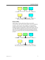
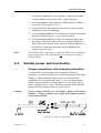
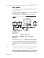
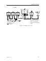
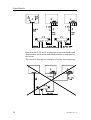
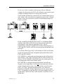
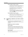
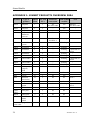
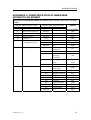
MANUAL
Simrad SimNet
Installation
This page is intentionally left blank
Installation Manual
SimNet Installation Manual
This manual is intended as a reference guide for correctly
installing the Simrad Intelligent Marine Network - SimNet.
Please take time to read this manual to get a thorough
understanding of SimNet, how data is exchanged data between the
products, the automatic interface setup and the selection of data
sources.
20222006 / Rev. A
1
Simrad SimNet
About this document
Rev
Date
Written by
Checked by
Approved by
A
11.11.04
NG
ThH
JL
First edition
© 2004 Simrad AS. All rights reserved.
No part of this work covered by the copyright hereon may be reproduced or
otherwise copied without prior permission from Simrad AS.
The information contained in this document is subject to change without prior
notice. Simrad AS shall not be liable for errors contained herein, or for incidental
or consequential damages in connection with the furnishing, performance, or use
of this document.
2
20222006 / Rev. A
Installation Manual
Contents
1
Description.................................................................................................... 5
1.1 SimNet - Simrad Intelligent Marine Network ...................................... 5
1.2 Integration of SimNet and NMEA2000 products ................................. 6
SimNet products on a NMEA2000 network (backbone)...................... 6
Connection of NMEA2000 products to SimNet................................... 7
1.3 Technical description ............................................................................ 8
1.4 Network backbone ................................................................................ 8
Daisy chain............................................................................................ 8
Drop cable ............................................................................................. 9
Termination ......................................................................................... 10
2
Technical specifications............................................................................. 11
3
Installation.................................................................................................. 12
3.1 Planning the installation...................................................................... 12
3.2 Select the SimNet accessories you need ............................................. 12
3.3 SimNet power and termination ........................................................... 13
Power connection and network protection.......................................... 13
Small system ....................................................................................... 15
Total network load and System Size Factor ....................................... 15
Medium system (SF<600)................................................................... 16
Large System (SF < 2000) .................................................................. 18
Extra large Systems (SF > 2000) ........................................................ 20
Connecting SimNet products to a NMEA2000 network .................... 20
Planning and installing a NMEA2000 network.................................. 21
3.4 Performing the installation.................................................................. 22
Finding the SimNet connector(s) on the product................................ 22
Network cable installation .................................................................. 22
NMEA0183 interface.......................................................................... 23
3.5 Plug and Play interface setup .............................................................. 25
20222006 / Rev. A
3
Simrad SimNet
SimNet class 1 products...................................................................... 25
SimNet class 2 products...................................................................... 26
Simrad group or stand alone configuration......................................... 26
Using Plug & Play to set up a SimNet Class 1 system ....................... 28
Using Plug & Play to set up a Class 2 SimNet system ....................... 28
3.6 Identification of Data Sources ............................................................ 29
Simrad products .................................................................................. 30
3.7 Adding a SimNet product to an existing SimNet system ................... 31
Adding a transducer (data source) to the existing network ................ 31
Adding a Class 1 product.................................................................... 31
Adding a Class 2 product.................................................................... 31
3.8 Replacing a defective unit with a similar unit .................................... 32
Replacing an active transducer ........................................................... 32
Replacing a SimNet Class 1 product with a similar product .............. 33
Replacing a SimNet class 2 product with a similar product ............... 33
4
TROUBLE shooting .................................................................................. 34
4.1 Class 1 system ..................................................................................... 34
4.2 Class 2 system ..................................................................................... 35
5
Glossary ...................................................................................................... 36
Appendix 1: SimNet products overview 2004.................................................. 38
Appendix 2: Definition of DataTypes ............................................................... 40
Appendix 3: Identification of NMEA2000 products on SimNet .................... 41
Appendix 4: SimNet cables and accessories..................................................... 44
Appendix 5: NMEA Data Conversion.............................................................. 46
4
20222006 / Rev. A
Installation Manual
1
DESCRIPTION
1.1
SimNet - Simrad Intelligent Marine
Network
`lj_f
`lj_f
pfjo^a=fpNO
ifdeq
^i^oj
qfjbo
rmmbo
fkcl
pfjo^a=fpNO
iltbo
fkcl
ifdeq
^i^oj
qfjbo
rmmbo
fkcl
a^q^
`lj_f
pfjo^a=fpNO
pfjo^a=fpNO
iltbo
fkcl
ifdeq
^i^oj
qfjbo
rmmbo
fkcl
iltbo
fkcl
ifdeq
m^db
rmmbo
fkcl
iltbo
fkcl
STBY
PWR
AUTO
NAV
WIND
DODGE
INFO
Figure 1-1 SimNet network
SimNet is a data network that makes interconnection and
integration of Simrad products simple. SimNet permits the
exchange of data between the interfaced products and enables
the flow of commands and proprietary instructions between the
various SimNet compatible products. The data transfer capability
of SimNet is 50 times higher than the NMEA0183 standard.
SimNet is based on NMEA2000, the marine industry’s new
standard for interfacing equipment. The majority of SimNet
products are NMEA2000 certified (page 38).
The advanced SimNet Plug & Play (P&P) software provides
flexibility and automatic interface capability to Simrad products.
Interface of previous models of Simrad products that are not
SimNet compatible and non-Simrad products also benefit from
this P&P software. (See page 38 for SimNet compatible
products.) Products with only NMEA0183 interface capability
can be connected to SimNet via separate converter units (page
23, 44) or via Simrad products that has a built-in capability to
convert NMEA0183 to SimNet (page 38).
20222006 / Rev. A
5
Simrad SimNet
SimNet accepts multiple sources of equivalent data and
automatically selects the preferred sources for a group of
integrated Simrad products. Alternative sources can be selected
manually.
The SimNet accessory program offers a wide selection of parts
necessary to complete a professional installation. The cable
system, designed with small plugs at both ends is easy to run,
requiring only 10 mm (3/8”) holes through bulkheads and panels
(page 44).
1.2
Integration of SimNet and NMEA2000
products
SimNet’s flexibility enables the interface of NMEA2000
certified SimNet products into a NMEA2000 data network. Only
a single NMEA2000 to SimNet drop cable is required, and this
cable is part of the SimNet accessory program (page 44).
SimNet products on a NMEA2000 network
(backbone)
On a NMEA2000 data network with other manufactures certified
products, all Simrad products will benefit from the advanced
SimNet P&P software which automatically sets up the data
sources that each Simrad product needs – not only data supplied
from other Simrad products, but also data supplied from other
manufactures products via NMEA2000.
SimNet to
NMEA2000
cable
NMEA2000 Backbone
Term.
Term.
AT15
NMEA 2000
Product 1
NMEA2000
T- joint
Net power
supply or
12V battery
Certified NMEA2000 Level A or B products only !
6
20222006 / Rev. A
Installation Manual
Note !
Whenever SimNet products are connected to a NMEA2000
network, the NMEA2000 specified cable system shall be used
and the NMEA2000 installation guidelines must be followed.
Connection of NMEA2000 products to
SimNet
The physical layer (backbone cabling) of SimNet is different
from that of NMEA2000. Whilst NMEA2000 only permits drop
cabling, SimNet also offers daisy chaining of products which
significantly simplifies the installation and save costs on both
labour and materials. Other manufacturer's products may be
connected to a SimNet network provided they are SimNet
compatible. To be SimNet compatible the NMEA2000
product(s) must:
• Be NMEA2000 Certified
• Meet the CE, FCC regulations with a SimNet adaptor cable
connected.
• Not exceed the SimNet load specifications (page 15)
− Recommended load is ≤ 3NLs
− Absolute maximum load is 10NLs (= 0.5Amps)
This is to ensure a trouble free performance of a large SimNet
network during setup and operation, and when new products are
added at a later stage.
Note !
Simrad can take no responsibility if problems occur on SimNet
due to a NMEA2000 product that has been connected.
12V
battery
Active Tee
SimNet
adapter
cable
Universal
NMEA
converter
SimNet
compatible
NMEA2000
product
SimNet compatible
NMEA2000 Active
Transducer
20222006 / Rev. A
7
Simrad SimNet
1.3
Technical description
SimNet (and NMEA2000) are based on the proven CAN bus that
is widely accepted in automotive, agriculture and process control
applications.
The physical data network consist of the standard SimNet cable,
where one twisted pair of wires will distribute data, and a second
set of slightly heavier twisted pair will supply power for the data
bus.
Simrad products with low power consumption such as the IS12
instrument system, and various active sensors will be powered
directly from the data bus cable. Products that consume more
power, like chartplotters and autopilots, require a separate power
connection in addition to the SimNet connection.
The SimNet software is derived from the NMEA2000
communication protocols and adapted to Simrad’s own needs for
data transfer and proprietary control.
Daisy chaining
T-joiner with drop cable
SimNet products are designed for daisy chaining (two SimNet
connectors on the product) or for connection via drop cable and
a SimNet T-joiner (products with one SimNet connector).
1.4
Note !
Network backbone
The SimNet backbone must be kept intact when a product is
removed from the network.
Daisy chain
Daisy chaining is a simple method of interconnecting products
mounted adjacent to each other in a panel. If a daisy chained
product is removed for any reason, a T-joiner must be used to
reestablish the backbone of the network.
8
20222006 / Rev. A
Installation Manual
T - joiner
Insert a T-joiner to keep the SimNet intact
Drop cable
When using a T-joiner and a drop cable you can easily
disconnect the drop cable from the product without breaking the
backbone of the network. This method is recommended for
products that are bracket mounted. Products suitable for daisy
chaining can also be connected via a drop cable. In that case only
one of the SimNet connectors needs to be used. The connector
that is not in use should be protected by the SimNet protection
plug on the product itself, or by one from the SimNet accessory
program.
Disconnecting the drop cable has no effect on SimNet
20222006 / Rev. A
9
Simrad SimNet
Termination
At both ends of the network backbone there must be a plug that
contains a built in termination resistor. A variety of accessories
with built in termination are available (page 44). A plug with a
termination resistor is easy to recognize by the red disc on the
plug face.
Red disc
Note !
10
The IS12 Wind Transducer (MHU) has a built in terminator. The
two plugs on the thin mast cable have both a yellow face;
however, the mating connector on the transducer wand is red.
20222006 / Rev. A
Installation Manual
2
TECHNICAL SPECIFICATIONS
The following specifications are for a standard SimNet system 1:
Maximum number of products connected in a network: ..................................... 50
Maximum total cable length: ........................................................120 meter (400’)
Bit rate on the bus: (50 times faster than NMEA0183)................250 Kbit / second
Maximum DC current through a single SimNet plug / connector joint:............. 5A
Maximum number of network loads (NL’s) ................................................ 80 NL2
SimNet power supply: ......................................................................... 12 V Battery
or 15 V Power supply 3
Maximum drop cable length:...............................................................6 meter (20’)
Maximum total length of all drop cables (accumulated): ...............60 meter (200’)
Environment: Cable and plug/connector system............... Dust/water: IP66 (IP67)
Temperature: .......................................................................................70oC (158oF)
1
If your requirement exceeds what you find in the general specifications,
you should contact your local Simrad representative.
2
A NMEA2000 specification: 1NL equals maximum 50 mA current load on
the network power cable, e.g. a 3NL product will use maximum 150 mA
from the SimNet (node) connection.
3
Must be a standard NMEA2000 power supply with galvanic isolation and
current limiter.
20222006 / Rev. A
11
Simrad SimNet
3
INSTALLATION
SimNet is very easy to install but to get the best and most
reliable result you should use the following guidelines and plan a
little ahead of starting to route and connect the cables.
Simrad can provide you with a range of SimNet accessories that
will make your installation easy and professional looking (page
44).
3.1
Planning the installation
First, determine the best location on the vessel to mount the
SimNet products, and other products only equipped with
NMEA0183 interface. Due to SimNet’s flexibility you need not
take any particular precautions when placing the products.
You may connect each NMEA0183 product to SimNet via the
AT10 Universal NMEA0183 Converter (single input and output)
and the Simrad IS15 instrument system via the AT15 SimNet
converter. You will find these as part of the SimNet accessory
program (page 44).
Some of the SimNet products have a built in NMEA0183
converter function that will make selected data available to and
from SimNet, but be aware of the limitations it may imply. (See
Appendix 1, page 38, for more details).
Note !
3.2
On the autopilots the NMEA0183 ports are not on the control
units and you have to plan with this in mind if you are not using
AT10 as interface. The NMEA0183 connections are described in
the autopilot manual.
Select the SimNet accessories you need
1. Find the shortest and easiest way to route the SimNet cables
from product to product.
2. Determine the required amount of standard cables and other
accessories from the SimNet accessory program; keep cables
as short as possible. If you plan to extend the SimNet system
at a later stage, it might be useful to add a few T-joiners in
appropriate locations for easy access to the network. They
12
20222006 / Rev. A
Installation Manual
can later be replaced by a new product, or the new product
can be connected via a drop cable – quick and easy!
3. Note the product(s) that will need a NMEA0183 to SimNet
converter (AT10 and/or AT15).
4. Use the SimNet cable gland for an attractive and protected
bulkhead or panel feed through.
5. Use the SimNet Bulkhead Tee connector to make a solid and
protected SimNet outlet, e.g. for remote controls.
6. Use the standard SimNet T-joiner to connect products that
are bracket mounted (or have only one SimNet connector).
This will prevent a break in the network cable (backbone) if
the product is removed. Alternatively the Bulkhead Tee
connector can be used.
The SimNet IS12 wind sensor is supplied with a special 30 meter
light weight cable. This cable must not be used as an ordinary
network cable.
Note !
3.3
SimNet power and termination
Power connection and network protection
A separate DC power supply to the network backbone is
necessary to operate the network. A solid connection to the ships
battery or other stable DC supply source is essential to the
installation (See specifications, page 11). It is recommended to
include a circuit breaker or switch and a 5 A slow blow fuse in
series with the battery + wire. The fuse is to protect the SimNet
plug and cable system in case of a short-circuit.
Caution !
Do not connect SimNet to a 24V battery. Observe the battery
polarity. – Wrong polarity and voltage will damage products
connected to SimNet.
Figure 3-1 Power connection
20222006 / Rev. A
13
Simrad SimNet
For reliable network performance use the following guidelines:
• Connect the battery to the network power wires at one
single point to avoid interfering noise loops.
• Use good quality and saltwater resistant accessories
(circuit breaker, fuse holder, power cable terminals)
• Use at least 2x1.0 mm2 (16 AWG) cable if you need to
extend the standard SimNet power cable (2m / 6.7’) to
reach the battery, and remember to add the length of this
to the total SimNet cable length (L - page 15) when you
are planning your system.
Using a heavier gauge cable between the battery and the SimNet
power cable will reduce the effect on the total network cable
length (L). (See Figure 3-1 and page 16.)
− 2 x 3.0 mm2 (12 AWG) add only 1/5 of the extended cable
length as additional L.
− 2 x 4.0 mm2 (10 AWG) add only 1/6 of the extended cable
length as additional L.
− 2 x 6.0 mm2 (8 AWG) add only 1/10 of the extended cable
length as additional L.
14
20222006 / Rev. A
Installation Manual
Small system
– A system consisting of up to 5 SimNet products and up to 7
meters (23’) total length (L) of SimNet cable including the
SimNet power cable.
In a small system you need the SimNet power cable with built in
termination (red disc on cable plug).
Connect the products in a daisy chain or use drop cables as
recommended in the introduction. A second termination is not
required.
`lj_f
`lj_f
pfjo^a=fpNO
pfjo^a=fpNO
STBY
PWR
ifdeq
^i^oj
qfjbo
rmmbo
fkcl
iltbo
fkcl
ifdeq
^i^oj
qfjbo
rmmbo
fkcl
iltbo
fkcl
INFO
SETUP
10 10
AUTO
NAV
WIND
1
1
TURN
DODGE
Red plug Power Cable
(with termination !!)
to 12 V battery
Figure 3-2 Small system
Proceed directly to paragraph 3.4 (page 22) for further
instructions.
Total network load and System Size Factor
As with all network systems some basic rules must be observed
in relation to the size of the network. The System Size Factor
determines the size of a SimNet network based on load and cable
length.
Note !
20222006 / Rev. A
Because of the high data rate the network shall be terminated at
each end to match the characteristic impedance of the network
cable. Do not use more than two terminations or place the
termination(s) away from the network ends. If cables are
extended beyond the termination point, they are to be considered
drop cables to the network and the length is limited to 6 m (20’).
15
Simrad SimNet
In the table on page 38 you will find the Network Load (NL)
value for each SimNet product, if not look in the technical
specifications for that product.
This is how you determine the System Size Factor (SF):
1. Add all the NL’s to get the total network load = NLtot
2. Add up the total cable length excluding the 30 meter (99’)
wind sensor cable but including the effect of an extended
power cable as explained on page 14. Resulting cable
length = Ltot
3. Determine the System Size Factor; SF = NLtot • Ltot
The following paragraphs refer to systems with a system factor
below 600 (medium), between 600-2000 (large) and above 2000
(extra large).
Note !
The above calculations were based on the Ltot being measured
in meters. If the Ltot is measured in feet, multiply by 0.3 to
determine the System Size Factor, SF.
SF = NLtot • Ltot(feet) • 0.3
Medium system (SF<600)
In a medium system you need the SimNet power cable with built
in termination (red disc on plug) at one end and a wind sensor
(has built in termination), or a termination plug in the other end
of the network. You may use drop cables but observe the
limitations given in the technical specifications (page 11).
16
20222006 / Rev. A
Installation Manual
Example:
`lj_f
a^q^
`lj_f
pfjo^a=fpNO
pfjo^a=fpNO
pfjo^a=fpNO
STBY
PWR
ifdeq
^i^oj
qfjbo
rmmbo
fkcl
iltbo
fkcl
ifdeq
^i^oj
qfjbo
rmmbo
fkcl
iltbo
fkcl
Red plug Power Cable
(with termination !!)
to 12 V battery
ifdeq
m^db
rmmbo
fkcl
iltbo
fkcl
INFO
SETUP
10 10
AUTO
NAV
WIND
1
1
TURN
DODGE
End point termination
plug, or wind sensor
with build in termination
(2 NL)
Figure 3-3 Medium size system
20222006 / Rev. A
17
Simrad SimNet
The drawing shows a SimNet system consisting of:
Cable length (L)
Network Load (NL)
Power cable
2m (6,5’)
IS12
(3x2NL)
instruments
6NL
Cable between instruments
2x2m (6,5’)
4m (13’)
CP34 Chartplotter
1NL
IS12 – T-joiner
10m (33’)
Autopilot
1NL
Drop cable
2m (6,5’)
IS12 Wind sensor
2NL
T-joiner - autopilot
5m (16’)
Total cable length (Ltot)
23m (75’)
Total network load NLtot 10NL
This adds up to a system with SF = Ltot • NLtot (meter) = 230,
alternatively SF = Ltot • NLtot (feet) • 0,3 = 225
The special 30 meter wind transducer (MHU) cable is accounted
for in the calculations, and shall be excluded from Ltot.
The system is well within the SF600 limit. There is even room
for future expansion with more SimNet products.
Note !
SimNet is designed to be very robust, and in a medium size
system with relative short cables you may find that the system
will perform with only one terminator. It is, however,
recommended that you use the end point termination to retain
the best possible protection against interference.
Large System (SF < 2000)
When the network gets bigger and the power consumption and
cable length increases, it is important to feed the supply in the
centre of the network to reduce power loss in the network cables.
You will need a SimNet power cable without termination
(yellow disc on plug) and a termination plug at each end of the
network. The wind sensor, if installed has a built in termination
and will replace one of the terminators. You may use drop cables
from T-joiners but observe the limitations given in the technical
specifications (page 11).
18
20222006 / Rev. A
Installation Manual
Example:
Figure 3-4 Large system
16 products interconnected via 92 meter (306’) network cable
The best place to feed the network power is the point where the
SF (L ● NL) value in each of the branches is most equal.
However, it will work without problems as long as the SF value
in each branch is below 600.
• Determine the total NL values separately for both the left
and right branches.
• Add up the cable length separately for each of the two
branches (exclude the 30 meter wind sensor cable).
• Calculate the SF (left) and SF (right). Make sure that each
SF is below 600.
• If one branch has a too high SF, try to better balance the
network by moving the power cable and T-joiner into the
branch with the higher SF.
20222006 / Rev. A
19
Simrad SimNet
Left branch Right branch
Network loads (NL’s)
Total
Maximum
13
18
31
80
35 (114’)
27 (88’)
62 (202’)
120 (400’)
System Size Factor
SF = L x NL (x 0.3 if feet)
455
486
1922
Maximum System Size
Factor(SF)
600
600
2000
SimNet cable Length (L)
meter (ft.)
Remember:
1. The 30 m (99’) wind sensor cable should not be included
in the SimNet cable length (L) calculation.
2. The length of the power cable should be accounted for in
each branch calculation. Make sure you include the total
length of cable all the way to the battery. (See paragraph
3.3 for instructions on how to reduce the effect of an
extended power cable length)
Since all SF (L • NL) values are within the maximum limits this
system will perform to specifications.
Extra large Systems (SF > 2000)
Making an installation of an extra large network is more
complicated, and outside the scope of this manual.
If you are planning to install an extra large system, please
contact your local Simrad representative for assistance.
Connecting SimNet products to a
NMEA2000 network
SimNet products can operate on a NMEA2000 network.
To connect a SimNet product to an existing NMEA2000
network (backbone) you must use only one single SimNet to
Micro-C (drop) cable P/N 24005729 and connect it to a free
NMEA2000 Tee joiner (Micro-C connector).
Note !
20
Daisy chaining of products must not be made on a NMEA2000
network. Whenever SimNet and NMEA2000 products are
interconnected, the NMEA2000 cable system must be used and
the NMEA2000 installation guidelines must be followed.
20222006 / Rev. A
Installation Manual
The below figure shows the difference from Figure 3-2 if the
CP34 is replaced by an NMEA2000 certified chart plotter from
another manufacturer (not SimNet product).
`lj_f
`lj_f
pfjo^a=fpNO
pfjo^a=fpNO
STBY
PWR
ifdeq
^i^oj
qfjbo
rmmbo
fkcl
iltbo
fkcl
ifdeq
^i^oj
qfjbo
rmmbo
fkcl
iltbo
fkcl
INFO
SETUP
10 10
AUTO
NAV
WIND
1
1
TURN
DODGE
Figure 3-5 NMEA2000 network
Planning and installing a NMEA2000
network
NMEA2000 use different cable solutions with different
applications and network sizes.
NMEA2000 Light Cable installation
You can follow the guidelines on page 15 – 18 (disregard Figure
3-1, Figure 3-2, Figure 3-3) if you are using a NMEA2000 Light
Cable system with micro-C connectors and a network cable with
minimum 20 AWG (0.5 sq. mm.) power wires. 1
The NMEA2000 power cable does normally not include a
terminator. It is therefore important to install a terminator plug at
both ends of the network.
You must have a Tee connector (Micro-C) and a drop cable for
each product you want to connect. In addition you must have a
NMEA2000 power connector with 2 Micro-C connectors for the
network cable (Power Tee).
1
The minimum specified power wires for a NMEA2000 Light Cable is 22 AWG
(0.38 sq. mm.). In that case the system factor (SF) on page 15 must be calculated as:
SF = 1.3 • NLtot • Ltot.
20222006 / Rev. A
21
Simrad SimNet
NMEA2000 Heavy Cable installation or combined
heavy and light cables
If the network complexity (large system) requires the use of
heavy NMEA2000 cables, we recommend that you consult a
skilled technician for advice on how to get a proper network
layout and installation.
3.4
Performing the installation
Finding the SimNet connector(s) on the
product
The SimNet connector is easily recognizable on a product by its
yellow color.
Connect the yellow face cable plug to a yellow connector. In a
small or medium system the red face power cable plug must be
plugged into a yellow connector at either of the two end points
of the network.
A plug with a red face has a built in termination and is only used
in a small or medium system.
Note !
The first production lots of SimNet T-joiners were made with
black connectors. They can be used without problems in a
SimNet system with yellow plugs and connectors.
Network cable installation
Before beginning the installation make sure you have purchased
all the necessary standard cables and accessories to complete the
installation.
The SimNet bus is well protected against electrical interference,
however, it is always good practice to run data cables separate
from power cables (110/240V mains and 12/24V battery).
Pay special attention to power cables supplying high current for
electrical motors (hydraulic pumps), electronic fuel injection,
thrusters, refrigerators, echo sounders, radars, etc.
The light weight SimNet cable and plug system is well protected
against vibrations, but it is recommended to secure long cables,
not more than 50 cm (20”) from the SimNet connector.
22
20222006 / Rev. A
Installation Manual
NMEA0183 interface
Precautions
Observe the following when interfacing NMEA0183 devices to
SimNet:
1. NMEA0183 products that retransmit incoming
NMEA0183 data may cause a data loop back, resulting in
erratic readout and poor performance of the interfaced
products. – The SimNet AT10 and AT15 converters (see
below) are protected against loop back.
2. Use the AT10 Universal NMEA0183 converter, P/N
24005936 to connect NMEA0183 devices to SimNet if
there are no SimNet Class 1 products with NMEA0183
conversion connected to the system (page 38).
3. Avoid connecting identical NMEA0183 input data to
more than one SimNet product with the ability to convert
NMEA0183 data to SimNet format. This will load the
network unnecessary.
4. When interfacing Simrad IS15 instruments to SimNet, use
the AT15 converter, P/N 24005944.
Using AT10 and AT15 converters
The AT10 and AT15 are single product converters. To avoid
data loop back they are programmed to prevent data at the
NMEA output port to be transferred via SimNet back to the
NMEA input port. The only way to collect all available data is to
go via SimNet both ways. The below drawing illustrates the
principle of getting correct transfer of data.
20222006 / Rev. A
23
Simrad SimNet
Data from the A, B, and C products are present on SimNet and
distributed to and from the individual products as indicated by
the arrows.
The next two drawings are examples of wrong interconnection.
24
20222006 / Rev. A
Installation Manual
STBY
PWR
AUTO
NAV
WIND
SETUP
3.5
DODGE
Plug and Play interface setup
One of the SimNet features, the automatic interface setup system
– Auto Source Selection –, makes the remaining part of the
installation safe and easy. A total of 5 sources for each DataType
can be handled by Auto Source Selection.
SimNet class 1 products
These are advanced SimNet products with good display
capability that will, at first-time startup, take you through the
automatic data source selection process. Selecting the best data
source for each DataType1 is part of the process (page 40).
Class 1 products will even include NMEA0183 and autopilot
Robnet2 data sources in this automatic selection process, and
make the data available on SimNet.
Class 1 products will coordinate the source selection for all
SimNet products (Class1 and 2) in a “Simrad group”. Within that
group all products will use one common data source, e.g. the
same position source is used on the chartplotter, the autopilot
and the instruments when they are integrated. The same applies
for NMEA0183 products that are interfaced to SimNet via the
AT10 and AT15 converters since they are Class 2 products. Also
NMEA0183 devices that are connected to Class 1 products with
NMEA0183 to SimNet conversion capability (page 38) will use
the same source.
1
DataType is defined as a group of related data that you will expect to receive from
the same data source. E.g. DataType Position: Position (Lat, Long), COG, SOG,
GPS-quality, GPS Time, Datum. See Appendix 2 for details.
20222006 / Rev. A
25
Simrad SimNet
The way the source selection is processed and presented varies
on the different SimNet Class 1 products.
The individual product manuals will explain this in detail.
A network containing at least one SimNet Class 1 product is
referred to as a SimNet Class 1 system.
SimNet class 2 products
These are SimNet products with limited or no display capability.
They will automatically select the first available data source on
the network, lock onto that source and store it for future use. In
larger systems where a Class 1 product is present, Class 2
products will default to and follow the automatic (or manual)
selections made for the Simrad group by the Class 1 product.
A network containing no SimNet Class 1 product will in the
following be referred to as a SimNet Class 2 system.
Simrad group or stand alone configuration
Simrad group objective:
− To ensure that all products within the group use the very
same data source for each DataType.
− To make it easy to change data source for the entire Simrad
group of products.
− Provide automatic or manual source selection when
appropriate.
Note !
When one or more SimNet Class 1 product(s) are connected to
the bus, the one that is activated for automatic source selection
will establish the Simrad group. All other Simrad products will
join the group as default and use and present the same data.
It is possible to stay outside the Simrad group, i.e. “Stand alone”
with a single DataType or all DataTypes. This feature is useful if
you want to monitor one particular data source, e.g. a gyro
compass using an IS12 MEGA instrument as display.
In such cases you “exclude” the display from the group by
selecting the IS12 MEGA as a “stand alone” in the IS12 setup
procedure.
26
20222006 / Rev. A
Installation Manual
If you, on a Class 1 product in the group, select a different
compass for the group, the IS12 will continue to present the gyro
compass heading irrespective of the group selection.
Some SimNet products are restricted to use internal data sources
only. Hence, they can only be recognized as part of the “Simrad
group” if they are selected as source for the Simrad group on a
Class 1 product.
a^q^
pmbba
pfjo^a=fpNO
ifdeq
m^db
rmmbo
fkcl
abmqe
pfjo^a=fpNO
iltbo
fkcl
ifdeq
qfjbo
obpbq
pfjo^a=fpNO
fkcl
ifdeq
pe^ii
abbm
fkcl
a^q^
pfjo^a=fpNO
ifdeq
m^db
rmmbo
fkcl
iltbo
fkcl
In the system block diagram above EQ33 is a dedicated Echo
sounder (fish finder) and will not present external depth data
from SimNet, only internal depth data. EQ33 will be
automatically selected as depth source for the Simrad group, i.e.
CP33 and IS12 DATA will also use and present depth data from
the EQ33.
For all other DataTypes EQ33 will default to follow the Simrad
group and present the same navigation and position data as the
CP33 and IS12 DATA.
IS12 SPEED is a dedicated speed instrument and will therefore
only display “own” data, and supply these to other products on
the bus. So IS12 SPEED will be the source for water speed, log
and temperature data in the Simrad group.
IS12 DEPTH is a dedicated depth instrument and will only
display its own depth data. It will not be automatically selected
as the (Simrad group) source for depth in this system because
EQ33 is a Class 1 product that has priority. It is, however,
possible to manually change depth source for the group on the
CP33. All products except the EQ33 will then change to IS12 as
depth source. While the EQ33 will continue to present its own
depth data.
20222006 / Rev. A
27
Simrad SimNet
Using Plug & Play to set up a SimNet
Class 1 system
Verify that there is power on all SimNet products and any other
products interfaced to the system via NMEA0183 format.
Class 1 products will detect data activity on SimNet and
NMEA0183 input ports, and will prompt you on the display to
activate the automatic interface setup.
Note !
The display will vary depending on the type of product. Study the
manual for the individual SimNet products to get detailed
information.
Start the setup process from one of the Class 1 products
(Appendix 1, page 38) and follow the instructions on the display.
You will be guided through a quick automatic setup process. All
Class 2 products will follow the automatic source selection made
by the Class1 product.
With the source selection completed you can check the result on
any of the Class 1 products. If you prefer to make changes in the
automatic selection, see below.
Changing source on a Class 1 product
On Class 1 products you can manually change to other source(s)
for the individual DataTypes if you prefer to use one or more
sources different from the one(s) automatically selected.
Enter the Source Select or Interface menu on a SimNet Class 1
product to verify a selected source or make changes as per
instructions in the product manual. If the product is part of a
SimNet group that uses the actual DataType (Appendix 2, page
40), all members of the Simrad group will follow the new source
selection except the “stand alone”.
Note !
If you make a source change on a “Stand alone” product the
change will only apply to that product. Some products are
limited to be either “Stand alone” or part of the Simrad group
for all DataTypes.
Using Plug & Play to set up a Class 2
SimNet system
Single source
The system contains only one data source for each DataType:
28
20222006 / Rev. A
Installation Manual
1. Power up all the units on the SimNet bus and all
connected NMEA0183 products.
2. Make an NMEA0183 setup if required on the relevant
products as per the individual product manuals.
3. Verify that all data are present and displayed on all
connected products as expected.
Multiple sources
The system contains more than one data source for one or more
DataTypes:
1. Power up all the products except the ones that shall not be
used as data sources, i.e. power to only one source for
each DataType (Appendix 2).
2. Make NMEA0183 setup if necessary (See above).
3. Verify that all data are present and displayed on all
connected products as expected.
4. You may now power up the products that you do not want
to act as sources. – These products will be excluded as
sources for the group.
If it has no significance which source is selected, just power up
all units. The first one that is active with a specific DataType will
be selected as source and remembered.
Note !
If you make a mistake, a “Master Reset” or a “Source Reset”
will clear the source selection and you may try again. Refer to
the product manuals on how to perform a “Source reset” or
“Master Reset”.
If you perform a “Master Reset” on the autopilot, you will have
to make a complete setup as per the autopilot manual.
Note !
Changing source on a Class 2 product
To make a Class 2 product change data source will require a
master or source reset. After that, follow the procedure under
“Multiple sources” above.
3.6
Identification of Data Sources
SimNet identifies products by a set of rules described below. See
also Appendix 3 on page 41.
20222006 / Rev. A
29
Simrad SimNet
Simrad products
Simrad products that are also SimNet products, are identified by
their product name (e.g. CP34) and a SimNet number. Products
with a startup display will present the name and the SimNet
number. On other products, the SimNet number is the same as
the last 6 digits of the product serial number.
If you have 2 equal products in the system they may be
appointed a device instance number. This number will be
presented after the product name, e.g. CP34-1 and CP34-2. Refer
to the product manual for details.
Example: CP34-1 Chartplotter S/N004651 or short CP34-1
S/N04651
Identification of NMEA0183 or Robnet2 products
In the source/interface setup on products with NMEA0183
and/or Robnet2 (autopilot) interface capability, you can read
what DataType is selected and from which port.
-
NMEA0183 input will be identified as NMEA-x, where x
is the physical NMEA0183 port number.
Example: Navigation NMEA-1.
-
Robnet2 devices will be presented by “name”-0, Robnet2 is
always port number 0. Example: Compass RATE-0.
-
NMEA0183 products that are interfaced via AT10 will be
identified as an AT10 source. A device instance number
can be added to identify each AT10 if more than one are
connected. Default is AT10-0.
Example: Navigation AT10-1, Depth AT10-2.
NMEA2000 products (other manufactures):
These are identified with a short acronym (SimNet DeviceName)
and the instance number e.g. NAV-2 (see Appendix 3 for
details).
Also the name (max 32 characters) of the other manufacturers
product will in most cases be available for better identification of
the product, e.g. xxxx Airmar Transducer.
30
20222006 / Rev. A
Installation Manual
3.7
Adding a SimNet product to an existing
SimNet system
Adding a transducer (data source) to the
existing network
1. If it is a source for a DataType that is not available on
SimNet, it will be automatically detected and selected.
2. If it is an additional source for a DataType already
available on SimNet it will be detected but not
automatically selected. You have to make a manual
selection if you want it to be a source.
Adding a Class 1 product
When you add a Class 1 product to an existing SimNet system it
will ask you to power up all SimNet products. It will then detect
whether it is connected to a Class 1 system or not.
Note !
If it is a replacement product (has been setup before) it must be
given a “Master Reset” or “Source Reset” before it is connected
to SimNet.
Class 1 product to Class 1 system
The Class 1 product will adapt to the Simrad group source
selections that are already made, and it will automatically add to
SimNet (selections of) new sources not previously available or
used.
Class 1 product to Class 2 system
The Class 1 product will upgrade the SimNet Class 2 system to
Class 1 and make a new automatic source selection.
Note !
Follow the instructions on a Class 1 product and power on all
products in the system to let all sources be automatically
selected.
Adding a Class 2 product
If it is a replacement product (has been setup before) it must be
given a “Master Reset” or “Source Reset” before it is connected
to SimNet.
20222006 / Rev. A
31
Simrad SimNet
Class 2 product to Class 1 system
1. It will adapt to the Simrad group source selections that are
already made and use and present appropriate data.
2. If the added product is source for a DataType that has not
been available on SimNet, it will automatically be
selected by the Class 1 product(s) and added to the
Simrad group as a source
3. If it is a second source for a DataType already available
on SimNet it will not be automatically selected. You have
to make a manual selection on a Class 1 product in the
system to make it a source.
Class 2 product to Class 2 system
1. The new Class 2 product will automatically select the first
available data source for each DataType it needs.
2. If the new product is source for a DataType that has not
been available on SimNet, it will automatically be
selected as a new source by the other Class 2 products.
3.8
Replacing a defective unit with a similar
unit
It is important to observe the instructions below because SimNet
identifies each source as an individual one. It will not
automatically accept a replacement source even if the DataType
is identical.
Replacing an active transducer
Class 1 system
The replaced source is automatically selected from a Class 1
product by activating the Source Update function or by manual
selection in the source select menu. All products in the Simrad
group will be automatically updated. Standalone products must
be set up individually.
Class 2 system
Other products on the network may need a Source Reset to be
able to detect and utilize the new source.
32
20222006 / Rev. A
Installation Manual
Replacing a SimNet Class 1 product with a
similar product
The interface and source settings on the replacement product
must be cleared by a Source Reset or a Master Reset (like a new
product) prior to connecting it to SimNet.
When connected to the active SimNet the product will ask you to
“Start” the automatic Source selection. If there are other Class 1
products on the network it will automatically adapt to the
existing Simrad group setup and join in as a data source.
If there are no other Class 1 products on SimNet, the replaced
product will make a normal automatic source selection as
described on page 28.
Replacing a SimNet class 2 product with a
similar product
In a Class 1 system
The replacement product will automatically adapt to the Simrad
group setup on SimNet. If it is meant to work as Stand alone it
must be set up manually as in a first time installation (page 26).
In a Class 2 system
The replacement product shall normally be setup as if it was a
first time installation (page 28). Some products on the network
may need a Source Reset to detect the replaced product as a
source.
20222006 / Rev. A
33
Simrad SimNet
4
4.1
TROUBLE SHOOTING
Class 1 system
No Symptom
1
AutoSourceSelec
t does not start
automatically
2
Not all
DataTypes has
automatically got
a data source
appointed.
34
Possible Cause
Suggested solution
• There is no external
source connected to the
product (SimNet or
NMEA).
• Product has already been
setup once.
• There is no external data
source supplying the
required DataType
connected to the product
(SimNet or NMEA).
• The source may not send
out the DataType on
SimNet or NMEA.
• Check installation and
that all data sources are
powered up.
• Make a Source Selection
Reset or a Master reset of
the product.
• Check that there is a data
source for the DataType.
• Check that the data
source is correctly
installed and setup (if
required)
• Make a manual setup of
the missing source, or
use Source Select Update
function if available in
the product.
20222006 / Rev. A
Installation Manual
4.2
Class 2 system
No Symptom
Possible Cause
Suggested solution
1
No data from
SimNet are
displayed.
• SimNet cable not
connected
• No power on SimNet
• No termination plug in the
network
• Check installation
• Check switch and fuse
for SimNet power
2
Some data from
SimNet are
displayed but
not all
• Data source selection may
be locked on wrong or old
source.
• Source may be turned off
or not connected correctly
to power or network.
• Make a Source
Selection Reset or
master reset.
3
Unstable display
of SimNet data
• No termination in the
network
• Electrical interference from
other units on boat
• Not sufficient power in
endpoints of network.
• Insert a termination plug
as described in this
installation manual.
• Fit interference
suppressors to
equipment responsible.
• Check network DC
voltage in network
endpoints. (9 – 16VDC)
4
Only data on
some of the
products in the
network
• Loose or broken cables
• Product not connected to
the network / interface
• Check cables connected
to the first faulty unit,
replace if necessary.
20222006 / Rev. A
35
Simrad SimNet
5
GLOSSARY
Active transducer – A self-contained sensor or transducer that
outputs data on a format that is accepted by SimNet, e.g. SimNet
or NMEA2000.
NMEA0183 - A format (language) designed to permit
communication between various types of marine electronic
equipment. In essence this is a two-wire shielded, serial data
link, permitting one device to talk while other devices listen.
Numerous different sentences are available, permitting
communication between various different devices.
Note !
In order for any piece of equipment to engage in bi-directional
communication a pair of links is required.
NMEA2000 – A modern serial-data communications network to
interconnect marine electronic equipment onboard vessels.
Equipment designed to this standard will have the ability to
share data, including commands and status, with other
compatible equipment over a single signalling channel.
Note !
Only a single link is required for bi-directional communication
between products.
PGN – An acronym for Parameter Group Number. PGNs are
used in NMEA2000 analogues with the three capital letters used
in NMEA0183sentences, e.g. XTE.
Product ID – A number, suffix, acronym or term that can
identify a product.
Product name – The name of a Simrad product known from
sales and other literature.
Route - A stored sequence of waypoints. These waypoints will
be listed in the order in which you desire to follow them.
SimNet – An acronym for Simrad Intelligent Marine Network
based on the NMEA2000 communication protocols.
SimNet Source – Any product or device directly connected to
SimNet, or interfaced to SimNet from NMEA2000, NMEA0183
or Robnet2 formats.
Simrad Group – A number of Simrad products that are
selecting and sharing the same data sources via the SimNet
network.
36
20222006 / Rev. A
Installation Manual
Simrad Class 1 products – Simrad products that are SimNet
controllers, i.e. they have an appropriate display and software
that can set up and control the SimNet.
Simrad Class 2 products – Simrad products that do not contain
a SimNet controller. When connected to SimNet they will
automatically pick the first available source on SimNet and lock
on to that. When a Class 1 product is added to the Simrad Group,
Class 2 products will automatically subordinate themselves to
the Class 1 source selection.
20222006 / Rev. A
37
Simrad SimNet
APPENDIX 1: SIMNET PRODUCTS OVERVIEW 2004
Product
Type of
product
SimNet Net load
Class
NL’s
AP16
Autopilot
1
1
AP25
AP26
AT10
Autopilot
Autopilot
Universal
NMEA183
converter
Chart plotter
1
1
2
1
1
2
1
1
1
CX34
CX44
Combi Nav
System
NavStation
NavStation
CX54
EQ33
EQ44
EQ54
IS12
IS12
CP33
CX33
IS12
IS12
IS12
IS12
IS15
RS8x
TP22
TP32
WP32
HR22
NMEA2000
certified
Note
Yes
See Notes 1&2
“
“
Yes
Yes
Robnet2
See Notes 1&2
“
“
Yes
Yes
Pending
Pending
1
Yes
See Note 1
“
1
1
1
2
“
“
Pending
Pending
NavStation
Echo sounder
Echo sounder
1
1
1
2
1
2
“
“
“
Pending
Pending
Pending
Echo sounder
Mega
Data, Speed,
Compass,
Wind
Depth, Combi
Remote
Masthead
(wind trans)
Compass
Instrument
system
VHF series
Tiller pilot
1
2
2
2
2
2
“
Yes
No
Pending
Pending
Yes
2
Tr.
Tr.
9
1
1
No
No
No
Yes
Yes
No
Tr.
2
1
2
No
No
Yes
Pending
2
2
1
1
No
No
Yes
No
2
Tr.
1
1
No
No
No
No
0
No
No
Wheel pilot
TP/WP
remote
control
Termination plug and
power cable
38
NMEA183
conversion
Pending
Connected via
AT44
“
Connected via
AT44
“
Note 3
Connect via
AT15
20222006 / Rev. A
Installation Manual
− CA, CR, CE and other CP designated products can be
upgrated to SimNet but will not be NMEA2000 certified
− Tr. = Transducer (pure data source)
− Pending means that the product is in the process of being
NMEA2000 certified.
Notes!
1. NMEA0183 and Robnet2 data will be available on
SimNet only if the NMEA0183 or Robnet2 input is
selected as source on the Autopilot or the EQ and Cdesignated products listed above. These products are part
of the Simrad group as default, so this will be the source
selection for the Simrad group also.
2. The data source will on SimNet be recognized as APxx
(e.g. AP25), while it on the autopilot will display
differently, e.g. NMEA-1, referring to the specific NMEA
port.
3. Has built in termination and requires SimNet cable.
4. The Class 1 products convert a selection of NMEA0183
sentences to SimNet data. Refer to the individual product
manuals for information.
5. Always consider AT10 as an alternative to using a
Class 1 product as NMEA0183 converter because of it’s
capability to convert data (See page 46). It is also
powered by SimNet and makes data available without the
need to power a Class 1 product.
20222006 / Rev. A
39
Simrad SimNet
APPENDIX 2: DEFINITION OF DATATYPES
DataTypes is a group of related data that shall normally be
selected from the same data source.
DataType
DataType
Name
(long max. 20 ch)
Abbreviated name
(short max. 6 ch.)
Compass
Comp
Navigation
Nav
Position
Pos
Data content
Priority
Heading
Magvar
XTE
BWW
To WP
From WP
BWP
DWP
Position of WP
Time to go
WP name
Position
COG
1
2
SOG
Wind Apparent
Wind-A
Wind Calculated
Wind-C
Water Speed
Wa-Spd
UTC
Datum
User Datum settings
Magvar
Wind angle app.
Wind speed app.
Wind direction
Wind angle true
Wind speed true
Water speed
Water Temperature
Distance log water
W-Temp
DisLog
Water temperature
Cumulative log
Depth
Rudder
Autopilot
Depth
Rudder
APilot
Water depth
Ruder angle
Heading reference
Rudder commanded
40
PGN
127250
129283
129284
1
2
1
2
3
1
129301
129025
129026
130577
129026
130577
128259
129033
129044
129045
127250
130306
130306
1
2
128259
065406
130310
128275
065408
128267
127245
20222006 / Rev. A
Installation Manual
APPENDIX 3: IDENTIFICATION OF NMEA2000
PRODUCTS ON SIMNET
SimNet DeviceName based on NMEA2000 Device Class and Function
Code
NMEA 2000 Device Class
Dev.Cl
Device Class Name
00
10
20
25
30
Reserved for 2000 use
System tools
Safety systems
Gateway
Power management
and lighting systems
40
Steering systems
NMEA 2000 Function code
F.Code
unknown
unknown
unknown
010
130
140
unknown
130
140
150
160
50
Propulsion systems
unknown
130
140
150
160
170
180
190
200
210
unknown
20222006 / Rev. A
Function Name
Switch
Load
n.a.
Follow-up
Controller
Mode Controller
Automatic
Steering
Controller
Heading Sensors
Gyro
n.a.
Engineroom
monitoring
Engine Interface
Engine Controller
Engine Gateway
Control Head
Actuator
Gauge Interface
Gauge Large
Gauge Small
n.a.
SimNet
DeviceName
N2K
SYS
SAF
GWA
PMS
PML
PMX
FUC
MOC
APC
HCS
GYR
APX
PMO
PIN
PCU
PGW
PCH
PAC
PGI
PGL
PGS
PNX
41
Simrad SimNet
NMEA 2000 Device Class
NMEA 2000 Function code
Dev.Cl
Device Class Name
F.Code
60
Navigation systems
130
145
150
155
160
170
200
205
210
70
Communications
systems
220
unknown
130
140
150
160
170
180
190
unknown
42
Function Name
Sounder, depth
Global Nav Sat
System (GNSS)
Loran C
Speed Sensors
Turn Rate
Indicator
Integrated
Navigation
Radar and/or
Radar Plotting
ECDIS Elect.
Chart & Info Sys
ECS Electronic
Chart System
Direction Finder
n.a.
EPIRB
Emergency
Beacon
Automatic
Identification
System
DSC Digital
Selective Calling
Data Receiver
Satellite
MF/HF RadioTelephone
VHF RadioTelephone
n.a.
SimNet
DeviceName
EQS
GNS
LOC
WSS
TRI
NAV
RAD
ECD
ECS
DIR
NAX
EPI
AIS
DSC
DRX
SAT
RTM
VHF
COX
20222006 / Rev. A
Installation Manual
NMEA 2000 Device Class
Dev.Cl
80
Device Class Name
Instrumentation/
general systems
NMEA 2000 Function code
F.Code
130
140
150
160
170
180
190
200
Unknown
unknown
unknown
Function Name
Time/Date
systems
Voyage Data
Recorder
Integrated
Instrumentation
General Purpose
Displays
General Sensor
Box
Weather
Instruments
Transducer/
general
NMEA 0183
Converter
n.a.
SimNet
DeviceName
TIM
VDR
IIS
GPD
BOX
WTR
TDU
N83
ISX
NID
Description of the identification system:
Other manufactures products will be identified on SimNet by
their short SimNet DeviceName and their Device Instance
Number. In addition there will be an opportunity to view the
manufactures own product name (max. 32 charters) on most
class 1 products.
Unknown identification:
If the Function Code (FC) is unknown to the SimNet product,
the SimNet DeviceName for the appropriate Device Class will
be displayed with an unknown FC.
Example: ISX-3
IS: “Instrumentation/General System”
FC: X = Unknown,
-3: Instance number 3
If Device Class (and FC) is unknown to the SimNet product,
then NID – No IDentification – will be presented. The device
instance number will be shown if present e.g. NID-6.
In both cases the manufactures name (max. 32 charters) will be
available on most class 1 products.
20222006 / Rev. A
43
Simrad SimNet
APPENDIX 4: SIMNET CABLES AND ACCESSORIES
Art. no.
44
Description
24005829
0,3 m (1') SimNet cable
24005837
2 m (6.6') SimNet cable
24005845
5 m (16.6') SimNet cable
24005852
10 m (33') SimNet cable
24005860
SimNet T-joiner
24005878
SimNet cable gland
24005886
SimNet protection plug
24005894
SimNet termination plug
24005902
2 m (6.6') SimNet power w/termination
24005910
2 m (6.6') SimNet power w/o termination
24005936
AT10 Universal NMEA0183 converter
20222006 / Rev. A
Installation Manual
Art. no.
20222006 / Rev. A
Description
24005944
AT15 Active Tee connector, IS15
24005928
SimNet cable protection cap
24005729
SimNet Cable to Micro-C.
Adapter (drop) cable for SimNet products
in a NMEA2000 network.
45
Simrad SimNet
APPENDIX 5: NMEA DATA CONVERSION
AT10 data converted from SimNet/NMEA2000 to
NMEA0183 (TX) and vice versa (RX)
NMEA0183 sentence TX (max rate [Hz])
APB
0.5
BWC
0.5
BWR
DBT
DPT
1
GGA
GLL
HDG
4
HDT
4
HSC
0.1
MTW
0.2
MWV Relative Wind
1
MWV True Wind
1
RMA
RMB
0.5
RMC
0.5
RSA
3.33
VHW
0.5
VTG
0.5
VLW
0.5
VWR
WPL
XTE
ZDA
0.5
ZTG
RX
x
x
x
x
x
x
x
x
x
x
x
x
x
x
x
x
x
x
x
x
x
x
x
Open cells indicates no transmission or reception.
46
20222006 / Rev. A
Installation Manual
AT15 data converted from SimNet to IS15 (TX) and vice
versa (RX)
NMEA0183 sentence
BWC
BWW
BWR
DPT
HDG
HDT
HSC
MTW
MWV Relative wind
MWV True wind
RMB
RMC
RSA
VHW
VTG
VLW
XTE
ZDA
TX (max rate [Hz])
0.5
0.2
RX
1
4
4
0.5
0.2
4
X
0.5
0.5
5
1
0.5
X
X
X
X
X
0.5
0.5
Open cells indicates no transmission or reception.
20222006 / Rev. A
47
AP16-26 Autopilots, NMEA and SimNet messages
NMEA0183 sentence
APB
BOD
BWC
BWR
BWW
DBT
DPT
GGA
GLL
HDG
HDM
HDT
HSC
MTW
MWV
RMA
RMB
RMC
RSA
VBW
VHW
VLW
VPW
VTG
XTE
To-wp ident.; XTE
Bearing wp-wp, T
Bearing wp-wp, M
Bearing pos-wp, T
Bearing pos-wp, M
Magnetic variation
To wp ident.
Bearing wp-wp, T
Bearing wp-wp, M
To-wp position
To-wp ident.
Bearing pos-wp, T
Bearing pos-wp, M
Distance pos-wp
To-wp position
To-wp ident.
Bearing pos-wp, T
Bearing pos-wp, M
Distance pos-wp
Magnetic variation
To wp ident.
Bearing wp-wp, T
Bearing wp-wp, M
Depth ref transducer
AC NMEA-1 TX
(max rate [Hz])
AC NMEA-2 TX
(max rate [Hz])
x
x
x
x
x
x
x
x
x
x
x
x
x
x
x
x
x
x
x
x
x
x
x
x
x
x
x
0.5
x
x
0.5
x
x
x
x
x
x
x
x
x
0.1
0.1
Depth ref transducer
Transducer-Keel Offset
Present position
Present position
Compass heading, M, Magvar
Compass heading, M
Compass heading, T
Heading steer command
0.5
1
1
1
0.1
1
Speed through water
Speed through water
Log distance and trip
Velocity made good to
windward
COG, T/M
Magnetic variation
SOG
XTE
5
x
0.5
x
x
0.2
x
x
• Open cells indicates no transmission or reception.
• Messages to SimNet on the Rx port(s)
• Messages from SimNet on the Tx port(s)
1)
10 1
1
10 1
0.1
Water temperature
Apparent wind angle
Apparent wind speed
True wind angle
True wind speed
Present position
COG, T
Magnetic variation
SOG
To-wp position
To-wp ident.
Bearing pos-wp, T
Bearing pos-wp, M
Distance pos-wp, XTE
Waypoint closure velocity
Present position
COG, T
Magnetic variation
SOG
Rudder angle
AC NMEA- AC NMEA1 RX
2 RX
HDG out if magnetic sensor, HDT out if true sensor.