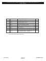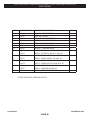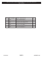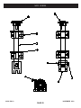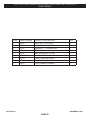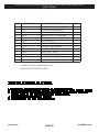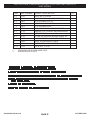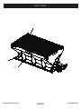
1
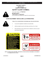
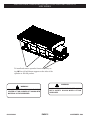
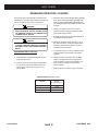
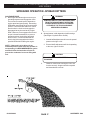
INSTALLATION, OPERATING INSTRUCTION AND PARTS MANUAL
MDV SERIES
MDV TM SPREADER SERIES
00122-588-03
1-739 R1
NOVEMBER 2009
INSTALLATION, OPERATING INSTRUCTION AND PARTS MANUAL
MDV SERIES
INSTALLATION, OPERATING INSTRUCTION AND PARTS MANUAL
MDV SERIES
INSTALLATION, OPERATING INSTRUCTION AND PARTS MANUAL
POLYHAWKTM PV SERIES
INSTALLATION, OPERATING INSTRUCTION AND PARTS MANUAL
POLYHAWKTM PV SERIES
INDEX
SAFETY ALERT .................................................................................................................. 3
INSTALLATION & ASSEMBLY INSTRUCTIONS ............................................................... 4 - 8
CENTER HIGH MOUNT STOP LAMP .................................................................................. 9
ELECTRIC THROTTLE CONTROLS (GAS ENGINE) ......................................................... 10
WIRELESS CONTROL INSTRUCTIONS.............................................................................. 11- 15
SPREADER LOADING.......................................................................................................... 16
SPREADER OPERATION ..................................................................................................... 17 - 18
SPREADER MAINTENANCE ............................................................................................... 19
SPREADER PARTS LISTINGS
REAR ENGINE GAS DRIVEN MODELS
...................................................................... 22 - 45
REAR ENGINE SPINNER .................................................................................................... 46 - 53
THROTTLE ASSEMBLIES ................................................................................................... 54 - 57
HYDRAULIC DRIVEN MODLES ........................................................................................... 58 - 67
SPINNER .................... ........................................................................................................ 68 - 71
DUAL VALVE ASSEMBLY .................................................................................................. 72 - 73
WARRANTY INFORMATION ...............................................................................................74
NAME PLATE INFORMATION ............................................................................................ 75
00122-443-01 Revision B
00122-588-01 Revision B
PAGE 2
00122-443-05 Revision B
00122-588-03
September 2009
OCTOBER 2009
September 2009
PAGE 2
NOVEMBER 2009
INSTALLATION, OPERATING INSTRUCTION AND PARTS MANUAL
MDV SERIES
THE BEST SAFETY
DEVICE IS A
CAREFUL OPERATOR!
SAFETY ALERT SYMBOL
THIS SYMBOL MEANS
ATTENTION!
BECOME ALERT!
YOUR SAFETY IS INVOLVED!
PLEASE READ AND UNDERSTAND COMPLETELY BEFORE DOING!
SAFE EQUIPMENT INSTALLERS and OPERATORS:
TURN OFF ALL POwER BEFORE PERFORMINg ANY SERVICE OPERATIONS
•
FOLLOW RECOMMENDED OPERATING PROCEDURES.
•
KEEP EQUIPMENT IN SAFE OPERATING CONDITION AT ALL TIMES.
•
RECOGNIZE AND AVOID HAZARDS WHILE OPERATING, SERVICING AND
MAINTAINING EQUIPMENT.
NOTICE: INSTRUCTIONAL MATERIAL AND PARTS LISTS INCLUDED IN THIS MANUAL ARE SUBJECT
TO CHANgE wITHOUT NOTICE.
00122-588-03
PAGE 3
NOVEMBER 2009
INSTALLATION, OPERATING INSTRUCTION AND PARTS MANUAL
MDV SERIES
INSTALLATION AND ASSEMBLY INSTRUCTIONS
CAUTION!
CAUTION!
READ ALL OF THE INSTALLATION
INSTRUCTIONS BEFORE STARTINg.
INSURE THAT THE SPREADER CANNOT TIP wHEN THE
SPINNER ASSEMBLY IS ATTACHED.
INSTALLATION INSTRUCTIONS:
2. Attach or lower spinner assembly.
The Meyer MDV Spreader can be mounted and stored
as a single unit. The Meyer MDVTM Spreader will mount on
most 15,000 to 20,000 GVW and larger trucks.
TM
wARNINg!
THE SPREADER UNIT MUST BE SECURELY
FASTENED TO THE VEHICLE. FAILURE TO
PROPERLY RESTRAIN THE UNIT COULD
PERMIT THE UNIT TO BREAK FREE FROM THE
TRUCK AND CREATE A POTENTIAL FOR A LIFE
THREATINg ACCIDENT.
3. Position the spreader in the truck bed, just short of mak-
ing contact with the rear most part of the truck bed, bumper,
pintle hook etc. Bolt the unit to the truck using a minimum of
four (4) 1/2” Grade 5 bolts and corresponding washers and
locknuts. The spreader is designed to sit flat on the bed of the
truck, supported by the longitudinal
sides.
DO NOT SUPPORT THE SPREADER BY THE BODY
JACKS ALONE! UNIT IS NOT DESIgNED FOR CHASSIS
MOUNT APPLICATIONS!
CAUTION!
NOTE: TRANSPORTATION OF SPREADER MUST BE
DONE wITH SPINNER IN THE DOwN POSITION. DAMAgE MAY OCCUR IF TRANSPORTED IN RAISED POSITION.
DO NOT OVERLOAD THE VEHICLE
DO NOT LEAVE UNUSED MATERIAL
IN HOPPER.
4. Material could freeze causing the unit to not function correctly. Hopper should be emptied and cleaned after each use.
It is quite possible to overload the vehicle by improperly
mounting or overloading the spreader. This could result in
dangerous stability and braking problems. Always consult
and follow the truck manufacturer’s instructions.
CAUTION!
BEFORE STARTINg, VERIFY THAT THIS
MOUNTINg METHOD IS ACCEPTABLE TO THE
VEHICLE MANUFACTURER.
wARNINg!
BEFORE BEgINNINg ANY INSTALLATION ON THIS
UNIT, DISCONNECT THE SPREADER
BATTERY NEgATIVE CABLE IF ALREADY
INSTALLED.
1. Place the spreader in the rear of the truck with the engine/motor to the rear of the truck. Center the spreader(side
to side) in the truck.
00122-588-03
5. Attach the hold down at each corner of the hopper as
shown on page 5. Locate and drill four .531(17/32”) diameter
holes for eyebolts in the truck bed. Straps must be positioned
at opposing angles so that the spreader cannot slide forward
or rearward. Assemble ratchet/strap to eye bolts. Tighten
hold downs evenly. Do not overtighten,
damage will result to the spreader or the truck.
Note: If truck is equipped with sufficient tie downs, they
may be used in place of eyebolt.
PAGE 4
NOVEMBER 2009
INSTALLATION, OPERATING INSTRUCTION AND PARTS MANUAL
MDV SERIES
To install and remove spreader from truck, lift by using the four (4) hold down supports on the sides of the
spreader or fork lift pockets.
wARNINg!
wARNINg!
ALwAYS USE SUFFICIENTLY RATED CHAIN
wITH SAFETY HOOKS wHEN LIFTINg
SPREADER.
DO NOT ATTEMPT TO LIFT SPREADER BY THE
CENTER LIFT OR CORNER LIFT HOOKS wITH
MATERIAL IN THE SPREADER.
00122-588-03
PAGE 5
NOVEMBER 2009
INSTALLATION, OPERATING INSTRUCTION AND PARTS MANUAL
MDV SERIES
INSTALLATION AND ASSEMBLY INSTRUCTIONS
OPTIONAL HOLD DOwN KIT
62562
1
* Photo for hold down reference only, not MDV installation. MDV cannot be installed in pick-up type vehicles.
tem
1
N/S
N/S
N/S
N/S
art Number
62602
62807
20307
62604
62605
Qty.
4
4
4
4
8
Description
Ratchet/Strap
Bolt, 1/2” Eye
Locknut, 1/2-13 Nylon Insert ZP
Nut, 12-13 Hex ZP
Flat washer, 3/4” U.S.S. ZP
N/S = NOT SHOWN
NOTE: If truck is equipped with sufficient tie downs, they may be used in place of eyebolt.
00122-588-03
PAGE 6
NOVEMBER 2009
INSTALLATION, OPERATING INSTRUCTION AND PARTS MANUAL
MDV SERIES
INSTALLATION INSTRUCTIONS
HYDRAULIC CONTROLS
7. Use hose manufacturers recommendations for
fitting reusable hose ends.
wARNINg!
LEAKINg HIgH PRESSURE FLUIDS CAN INJECT
THEMSELVES UNDER THE SKIN OF PERSONS
NEAR A LEAK, CREATINg gRAVE MEDICAL
RISKS. TAKE CARE TO AVOID EXPOSURE TO
HIgH PRESSURE FLUIDS.
8. Hydraulic pumps must be mounted so shaft
rotates in direction of arrow.
9. Locate reservoir as close to pump as possible. It
may be installed on truck frame or truck box.
10. Hydraulic return line filter is screwed directly onto
reservoir with cartridge down. Oil must flow
through filter in direction of arrow on filter.
1. Hydraulic components should be kept as clean
as possible during assembly operations.
2. Galvanized pipe and pipe fittings must not be
used because flaking of galvanizing material can
cause damage to major hydraulic components.
11. Install the quick connect couplings so that when
disconnected, there is a male and female on the
truck as well as on the spreader. This way hoses
will always be hooked up properly, and hose ends
can be coupled together when spreader is in
storage to prevent system contamination.
3. A pipe joint sealant, compatible with hydraulic oil,
must be applied to all NPT fittings. Teflon tape is
not recommended. Do not apply pipe joint
sealant to ORB or JIC fittings.
12. See page 9 for valve assembly.
4. Hose should be protected where severe wear may
be caused by vibration or sliding movement.
13. Operate hydraulic system for several minutes to
warm up. Check all connections for leaks.
5. Long runs of hose should be supported by tie
wiring or clamping.
14. After running, refill reservoir to three-fourths full.
6. Pressure and return hoses, connected to hydraulic motors, may be reversed for proper motor
rotation. Spinner rotates in a clockwise direction
when looking down from top.
CONTROL AND HYDRAULIC SYSTEM SPECIFICATION
*Hydraulic Oil ----------------------------- Good Grade of MS10W Hydraulic Oil which has
wear, oxidation and foam inhibitors.
*Oil Filter ----------------------------------- 10 Micron Element Return Line Filter
*Relief Valve Setting --------------------- 1500 PSI
*Oil Flow ----------------------------------- 0 - 10 GPM - With single flow valve connect
conveyor and spinner in series.
*Oil Flow ----------------------------------- 0 - 15 GPM - With dual flow valve connect separate
pressure line to conveyor and spinner motor.
7
00122-588-03
PAGE 7
NOVEMBER 2009
INSTALLATION, OPERATING INSTRUCTION AND PARTS MANUAL
MDV SERIES
INSTALLATION INSTRUCTIONS
DUAL FLOw VALVE/STAND
1. IMPORTANT: A pipe joint sealant compatible
with hydraulic oil must be applied to all NPT fittings.
Teflon Tape Sealant Is Not Recommended. Do not apply
pipe joint sealant to ORB or JIC fittings.
2. Hose ends connected to flow valve must be of the
“swivel”, type.
3. CAUTION: Over tightening of the fittings in flow
valve may cause damage to valve body.
4. Approximately 8” of hose slack must be realized
between the flow valve and valve stand after the flow
valve has been completely plumbed. If this condition
does not exist after the plumbing has been completed,
removal of valve will require hoses to be removed at
opposite end of valve.
5.
Assembly of valve on stand.
A. Cut a 5” x 5” square opening in floor board
of truck where the valve stand is to be located.
B. Bolt valve stand halves together forming a,
box over the 5” x 5” square opening. NOTE:
When bolting valve stand halves in place, make
sure holes in flanges align with holes in flange
plate.*
C. Bolt flange plate to VALVE (Use (2)
1/4” X 3” bolts, lockwashers, etc.)
D. Insert hoses through floor opening and valve
stand and connect appropriate hoses (see
instruction #1 thru #4) to flow valve.
E. Bolt flange plate to valve stand flanges.
(SEE PAGE XX PARTS LIST)
00122-588-03
PAGE 8
NOVEMBER 2009
INSTALLATION, OPERATING INSTRUCTION AND PARTS MANUAL
MDV SERIES
INSTALLATION INSTRUCTIONS
CENTER HIgH MOUNT STOP LAMP (CHMSL)
2. When drilling holes, any bare metal should be
coated with a rust preventative; use appropriate
size grommets and seal hole with appropriate
sealant.
wARNINg!
FEDERAL MOTOR VEHICLE SAFETY STANDARDS REQUIRE ALL TRUCKS, BUSES AND
MULTIPURPOSE PASSENgER VEHICLES
MANUFACTURED ON OR AFTER 5/1/1993, wITH
A gROSS VEHICLE wEIgHT RATINg (gVwR)
OF 10,000 LBS. OR LESS AND OVERALL
wIDTH LESS THAN 80” BE EQUIPPED wITH A
CENTER HIgH MOUNT STOP LAMP.
3. Allow for normal movement/twisting between cab
and chassis/pickup box when routing wires.
4. When spreader is removed from the truck, the
OEM CHMSL must be reconnected.
wARNINg!
NOTE: If the original equipment CHMSL is
obscured, an auxiliary CHMSL must be installed
to bring the vehicle back into compliance with
Federal Regulations.
CONSULT THE TRUCK MANUFACTURER FOR
AN APPROVED METHOD OF CONNECTINg AN
AUXILIARY CHMSL TO A PARTICULAR TRUCK
wHICH IS TO CARRY THE SPREADER. METHODS VARY wITH TRUCK MODELS, OPTIONAL
EQUIPMENT AND YEARS OF MANUFACTURER.
ELECTRICAL CONNECTIONS FOR AUXILIARY
CHMSL:
1. Use high quality butt connectors and shrink wrap
on all electrical splice connections. Wire should
be routed and secured to protect against
abrasion, sharp edges, and excessive movement.
It is highly recommended that wiring be placed in
convoluted tubing and secured with tie wraps.
Item
1
2
3
4
5
Part Number
62714
62715
62738
62364
63155
IMPROPER CONNECTIONS COULD RESULT IN A
VARIETY OF PROBLEMS AFFECTINg CRITICAL
SYSTEMS SUCH AS BRAKINg, ELECTRICAL AND
EMISSION! DON’T gUESS!
Qty.
1
1
1
1
1
Description
Lamp, Stop
Grommet, Mounting
Cable, Stop Lamp Power (Truck)
Cable, Light Power (Hopper)
Forming, Rear Stop Light Bracket
9
00122-588-03
PAGE 9
NOVEMBER 2009
INSTALLATION, OPERATING INSTRUCTION AND PARTS MANUAL
MDV SERIES
INSTALLATION INSTRUCTIONS
ELECTRIC THROTTLE CONTROLS
(FACTORY INSTALLED ACTUATORS)
9. It is recommended that a 12 volt battery with 40
ampere hour rating be installed for winter use.
The battery hold downs furnished will accept any
2SM series battery.
wARNINg!
BEFORE BEgINNINg ANY INSTALLATION ON
THIS UNIT, DISCONNECT THE SPREADER
BATTERY NEgATIVE CABLE (IF ALREADY
INSTALLED).
1. Spreaders with factory installed throttle controls
do not require installer hookup to the engine. The
actuator has been installed and tested at the
factory.
2. Remove the engine shroud and securely place it
on the ground.
3. The throttle actuator cable plugs into the in-cab
control panel after being routed from the cab of
the vehicle to the rear of the mounted spreader.
4. Select a suitable location in the cab of the vehicle
to mount the spreader control box. (Do not
mount at this time.)
10. Attach the positive battery cable (each end
should have a red rubber boot) to the positive
terminal on the solenoid and to the terminal of
the battery. Make sure these protective boots are
covering the positive terminal post on the battery
and on the solenoid.
wARNINg!
USE SAFETY gLASSES OR OTHER FACE
PROTECTION AgAINST POSSIBLE BATTERY
EXPLOSION. DO NOT SMOKE AND AVOID
OTHER SOURCES OF IgNITION.
11. Connect the negative battery terminal to the
engine mounting bolt for proper grounding. When
finished, make sure all wires are away from hot or
moving parts and replace engine shroud.
12. Plug cable from spreader into socket mounted on
truck.
wARNINg!
CONSULT VEHICLE MANUFACTURER FOR
ACCEPTABLE MOUNTINg. THE CONTROL BOX
COULD INTERFERE wITH THE AIR BAg(S) AND
THE OTHER FUNCTIONS OF THE OCCUPANT
PROTECTIVE SYSTEMS, SUCH AS KNEE
BOLSTERS!
5. After the location of the control panel is determined, the cable must be routed to the front of
the spreader, securing as needed. Allow enough
cable for the control panel to be mounted in the
cab.
6. The routed cable must be clear of all moving or
hot parts on the spreader or the vehicle. Secure
the cable with the ties provided. Excess cable
must be coiled up and secured. Apply dielectric
grease to all connections for protection from the
salt spreading environment.
wARNINg!
NEVER OPERATE MACHINE wITH ENgINE
SHROUD REMOVED. NEVER CLIMB INTO THE
HOPPER wHILE THE ENgINE IS OPERATINg
OR CAPABLE OF BEINg OPERATED. SERIOUS
INJURY OR DEATH MIgHT OCCUR.
NOTE: Read and fully understand the owners
manual supplied by the engine manufacturer
before operating this equipment. Not doing so,
endangers your safety and the warranty of the
engine.
7. Mount the control panel (with the screws
supplied).
8. For a permanent cable mount, a mounting
bracket is supplied.
00122-588-03
6
PAGE
10
NOVEMBER 2009
INSTALLATION, OPERATING INSTRUCTION AND PARTS MANUAL
MDV SERIES
SPREADER OPERATION
wireless Throttle Control Button Functions
(Sequence of Operations)
Stop
Choke /
Throttle Fast
Start
Conveyor
Throttle Slow
A. ON/Off
System power activated (ready to
start). Spreader engine not running.
Spreader conveyor is not engaged.
F. TO TURN ENGINE OFF (With or without conveyor
running).
TURTLE
Push throttle slow button to
reduce setting to idle (this prevents
engine flooding and hard starting).
STOP
Push STOP button and hold
5 seconds.
B. START (Engine Only)
Open fuel shut off valve on engine.
CHOKE (Cold engine.) Hold down for
5 seconds to move the throttle
actuator to the choke position.
NOTE: Choking a warm engine may not be
necessary.
START
Hold down button until engine
starts.
TURTLE
Decreases throttle speed - adjust
as engine warms up. Will stop the
choke function.
RABBIT
Increases throttle speed.
NOTE: OFF can be pushed at anytime during
spreader operation to cut power to the unit;
however, you should normally use steps under F
above.
G. Do not attempt to start the engine
with the conveyor engaged.
H. Close fuel shut off valve on engine if
unit is to be transported while not
running.
C. TO ENGAGE SPREADER CONVEYOR
CONVEYOR
Push CONVEYOR switch only after
you are sure no one is in the hopper
or near the spinner!
wARNINg!
D. TO CONTROL CONVEYOR SPEED
RABBIT
Hold RABBIT to increase speed.
1. As with all power equipment, safety is the number
one concern.
2. Do not operate this equipment until you fully
understand how it functions.
3. Before starting engine, be sure that no one is near
the rear of the unit and that no one is inside the
unit!
4. Do not start the engine or engage the conveyor
(which is interconnected to the spinner) until
everyone is clear from moving parts and flying
material from the spinner.
Note DO NOT hold switch in HI position
after the desired RPM is achieved
or you will choke and/or stall the
engine.
TURTLE
Hold TURTLE to decrease speed.
E. TO DISENGAGE SPREADER CONVEYOR
CONVEYOR
Push conveyor button.
2
00122-588-03
PAGE 11
NOVEMBER 2009
INSTALLATION, OPERATING INSTRUCTION AND PARTS MANUAL
MDV SERIES
Swenson Spreader wireless Controller
The wireless controller is a compact unit with two parts. One part is the Base Unit (Receiver) and the
other part is the Transmitter (Hand Held Controller). The Transmitter is used to send a corresponding
signal to the Base Unit to act as a remote switching device.
Set-up and Operation
The Swenson Wireless Controller comes factory programmed. That means matching the Base Unit to
the Transmitter has been done by Swenson Spreader. This gives a matched (1 of 16 million combinations
@ 418MHz) interface between the Transmitter and Base Unit. See Figures 1 & 2 for Transmitter button
assignments. On the 8 button Swenson Spreader Transmitter, all (8) buttons are used when programming.
When programming is completed, only (5) buttons are functional (Buttons #1, #3, #4, #5, & #6) (see Fig.
1).
Button #7 (open button)
Button #8 (open button)
Button #5 (engine start)
Button #6 (engine off)
Button #3 (Throttle decrease)
Button #4 (Throttle increase)
& “Hold to Choke”
Button #1 (clutch on/off)
Button #2 (open button)
Fig. 1: Transmitter Front Button Assignments
“blue” LED
“ADD” Button
depress with paperclip
Fig. 2: Transmitter Back Button Assignments
00122-588-03
3
PAGE 12
NOVEMBER 2009
INSTALLATION, OPERATING INSTRUCTION AND PARTS MANUAL
MDV SERIES
“LEARN” Button
(“black” press button)
Programming “red” LED
Antenna (coiled)
Male Connector
Fig. 3: Base Unit layout (Figure shown without Base Unit Cover)
Programming/Reprogramming the Transmitter and the Base Unit:
Tools needed: A small “phillips” screwdriver and a small diameter pin (paper clip).
Instructions to program Transmitter and Base Unit:
1. Remove (4) screws and cover on Base Unit.
2. Power-up the Base Unit. Connect a 12V power source to the spreader 12V battery terminals and
plug the engine wire harness to the Base Unit wire harness (see Male Connector in Fig. 3). DO
NOT DISCONNECT THE BATTERY TERMINALS from the 12V source when engine is running.
3. On the backside of the Transmitter depress the “ADD” button (see Fig. 2) using a small pin or
paper clip – You will see a “blue” LED start to blink (for approximately 15-17 seconds).
4. On the front side of the Transmitter press all (8) buttons (see Fig. 1). There is no certain order to
press the buttons. Firmly press each button, separately. Perform this step before the 15-17 seconds
are up (before “blue” LED stops blinking). The Transmitter is now programmed and has created its
own 1 in 16 million address. Once the “blue” LED stops blinking, this step is completed.
5. On the Base Unit (see Fig. 3) press the black “LEARN” button. The “red” LED will start to blink
(for approximately 15-17 seconds).
6. On the front side of the Transmitter you only need to press Button #1 (clutch on/off), once.
Perform this step before the 15-17 seconds are up (before “red” LED stops blinking). The base unit
has now recognized the Transmitters unique 1 in 16 million address. Once the “red” LED stops
blinking, this step is completed.
7. Verify the (5) functional buttons (Buttons #1, #3, #4, #5, & #6) on the Transmitter are working with
the Spreader Unit by pressing each button, individually (the Base Unit “red” LED will flash when a
Transmitter button is pressed). If Transmitter buttons are not working, repeat steps 3 – 8 or see the
Trouble shooting directions.
8. When Transmitter buttons are functioning properly, re-assemble the Cover on the Base Unit with
the (4) screws. Your Swenson Wireless Controller is now ready to use!
00122-588-03
4
PAGE 13
NOVEMBER 2009
INSTALLATION, OPERATING INSTRUCTION AND PARTS MANUAL
MDV SERIES
Transmitter Battery Replacement
The Transmitter uses a standard CR2032 lithium button cell battery. In normal use it will provide 1 to 2
years of operation. To replace the Transmitter battery, gently press and slide the battery cover off.
Remove the battery by sliding (NOT lifting) it out from underneath the retainer (see Fig. 4). Observe the
battery polarity when replacing (“+” showing face up).
Notes:
1. If the battery looses power or is removed the Transmitter and Base Unit may need to be reprogrammed
(see reprogramming Transmitter and Base Unit instructions). Check Transmitter functional buttons to
verify if reprogramming is necessary.
2. When removing lithium battery, please use caution to slide not lift the battery from the controller! If
excess force is used to remove the battery (example: lifting the battery with a small screw driver) – the
solder connections from the battery clip to the circuit board could be pried loose. This action is not
covered under warranty.
Battery Cover
Lithium battery
Transmit
Fig. 4: Back of Transmitter with back cover and battery removed
Other Considerations
1. Powering off the engine will not automatically power off the Clutch (engagement of
conveyor/spinner). If clutch remains engaged, after engine is turned off, it could lead to a slow
electrical drain on the 12V battery.
2. If an unregulated voltage (example: sparking the battery cable terminal to the 12V battery post.) is
sent to the Base Unit it could erase the Base Unit programming. The remote may show signs of
no longer working with the Base Unit. Reprogramming will be required. When 14Amps are
supplied the Base Unit circuit board is designed to shut off. See additional trouble shooting
comments.
3. Only one transmitter at a time can be activated within a reception area. Only one carrier of a
particular frequency may occupy the same airspace at a given time. This means that if two
transmitters are activated in the same area at the same time the signals will interfere and the decoder
on the receiver will not see a valid transmission and the wireless controller will not function.
4. Multiple Transmitters can be programmed to (1) Base Unit.
5. To verify the Base Unit is receiving a signal from the Transmitter. Press a button on the Transmitter “red” LED on the Base Unit will light-up.
6. Swenson Spreader, LLC has no control over the intended usage of this product. Because of that
Swenson Spreader, LLC offers no written or expressed liability as to how this product is used.
Swenson Spreader, LLC recommends that these units are intended for OFF ROAD USE ONLY!
00122-588-03
5
PAGE 14
NOVEMBER 2009
INSTALLATION, OPERATING INSTRUCTION AND PARTS MANUAL
MDV SERIES
TROUBLE SHOOTING
1. To verify the Transmitter and Base Unit are working together: Once the base unit has power the
“red” LED will come on when the Transmitter buttons are depressed (Cover of Base Unit will need
to be removed to see “red” LED). If the “red” LED does not come on, the Base Unit is NOT
getting a signal from the Transmitter.
Possible Solutions:
A. Reprogramming the Transmitter and Base Unit might be required.
B. Base Unit might not be functioning properly (see Base Unit trouble shooting below).
C. Transmitter might not be functioning properly. (see Transmitter trouble shooting below).
2. Base Unit Programming Lose: If an unregulated voltage (spark) is sent to the Base Unit from a
power source the Base Unit could lose its programming. The voltage spike will not damage the
Base Unit or Transmitter. Unregulated voltage could generate from the following:
- Connecting battery cables to a 12V battery source.
- Jump starting the 12V battery.
- Charging the 12V battery.
- Pull-starting the engine.
Possible Solutions:
A. Reprogramming the Transmitter and Base Unit may be required.
B. Base Unit might be damaged, a new Base Unit & Transmitter will need to be ordered.
3. Base Unit does not function properly: (example: “red” LED will not light up when “LEARN”
button is depressed on Base Unit).
Possible Solutions:
A. Check/verify voltage of 12V is being supplied by the 12V battery. Lower voltages than 12V
will not allow the Base Unit to function properly.
B. Confirm all wires on engine wire harness are secure and properly connected.
C. Base Unit could be damaged, a new Base Unit & Transmitter will need to be ordered.
4. Transmitter does not have power: (example: “blue” LED will not light up when “ADD” button is
depressed on Transmitter).
Possible Solutions:
A. Verify tool diameter (example: paperclip) to depress Transmitter “ADD” button is small
enough to enter the “ADD” button hole.
B. Verify the lithium button cell battery polarity is correct (“+” will be facing up).
C. If the Transmitter is 1-2 years old, check the lithium battery voltage with a meter or replace the
battery as needed (CR2032 lithium button cell battery).
D. Transmitter could be damaged, a new Transmitter will need to be ordered.
5. General troubleshooting:
A. Try to Program/reprogram the Transmitter and Base Unit.
B. Verify the Ground wires (all wires) are secure.
C. Check connections to the components that the unit is trying to operate using a voltmeter.
WARNING
1. Disconnecting 12V Battery Cables/Terminals:
A. DO NOT DISCONNECT THE BATTERY (CABLES/TERMINALS) WHEN THE ENGINE
IS RUNNING. This could disable or permanently damage the Base Unit.
For further technical assistance please contact Swenson Spreader, LLC at (888) 825-7323 or visit us at
meyerproducts.com to download updated Wireless Controller Instructions.
00122-588-03
6 PAGE 15
NOVEMBER 2009
INSTALLATION, OPERATING INSTRUCTION AND PARTS MANUAL
MDV SERIES
SPREADER OPERATION - LOADINg
This manual covers vehicles which have been recommended for carrying the hopper spreader. Please see
your local dealer for proper vehicle applications.
3. Obtain the Gross Vehicle Weight Rating (GVWR),
Front Gross Axle Weight Rating (FGAWR), and
Rear Gross Axle Weight Rating (RGAWR) from
the certification label located inside the driver-side
door jam.
wARNINg!
OVERLOADINg COULD RESULT IN AN ACCIDENT OR DAMAgE. DO NOT EXCEED gVwR
OR gAwR AS FOUND ON THE DRIVER-SIDE
CORNERPOST OF VEHICLE.
4. With the occupants in the truck for normal
spreader operation, weigh the vehicle to obtain
gross vehicle weight (GVW).
5. Subtract the GVW from the GVWR to determine
the available material payload.
CAUTION!
6. Obtain the weight per cubic yard (lb./cu. yd.) of
the desired material. Divide the weight into the
payload to determine the maximum volume of
material that can be carried.
READ AND ADHERE TO MANUFACTURER’S ICE
CONTROL PACKAgE LABELINg INCLUDINg
MATERIAL SAFETY DATA SHEET REQUIREMENTS.
7. Compare the maximum volume to determine the
maximum height of the material in the hopper
spreader.
DETERMININg VEHICLE PAYLOAD
1. Install spreader and optional equipment according to the instructions.
8. Fill hopper with the material to the calculated
height. Reweigh vehicle with occupants and
verify the GVW, Front Gross Axle Weight, and
Rear Gross Axle Weight are less than the
vehicle’s ratings.
2. Install or attach any other equipment that will be
on the vehicle while the spreader will be in use
(step bumper, trailer hitch, snowplows, etc.).
Fill gas tanks.
9. Repeat steps 7 and 8 for each type of material.
Material weights (Reference Only)
Material
Density
(lb. per cubic yd.)
Salt (78lbs cu.ft.) - Dry
Coarse Sand - Dry
Course Sand - Wet
2,106
2,700
3,375
12
00122-588-03
PAGE 16
NOVEMBER 2009
INSTALLATION, OPERATING INSTRUCTION AND PARTS MANUAL
MDV SERIES
SPREADER OPERATION - SPREAD PATTERN
GAS ENGINE DRIVE
A. Start engine and allow engine to warm-up to
operating tempeture and engage the clutch.
The amount of material spread, depends on
engine speed and gate opening. Decreasing
RPM and/or gate height will decrease amount
spread. The inverse also holds true. Notice
that the electric clutch can be engaged or
disengaged at any time and at any engine
RPM. However, since engagement time and
torque is almost instantaneous, to prevent
premature spinner chain failure and chain
tension loss, it is recommended that the
electric clutch be engaged at the lowest
possible RPM without stalling the engine.
WARNING!
ALWAYS STAND AT A SAFE DISTANCE AWAY
FROM THE SPINNER WHILE OPERATING.
ALWAYS WEAR EYE PROTECTION WHEN
OUTSIDE OF THE TRUCK CAB WHILE
SPREADER IS RUNNING.
B. Spread pattern / width depends on baffle settings
(Gas Engine / Hydraulic Drive 4ft-30ft.)
1. Internal baffle adjustments will move the spread
pattern to the right or left.
2. External baffle adjustments will block spreading
to the rear, right or left side.
NOTE: If the truck is to be driven for an
extended period of time while the spreader is
not operating, it is RECOMMENDED the gas be
turned off at the fuel tank shut-off valve to
prevent the carburetor from over filling with
fuel.
CAUTION!
DO NOT LEAVE UNUSED MATERIAL
IN HOPPER.
C.
00122-588-03
Material could freeze causing the unit to not
function correctly. Hopper should be emptied
and cleaned after each use.
PAGE 17
13
NOVEMBER 2009
INSTALLATION, OPERATING INSTRUCTION AND PARTS MANUAL
MDV SERIES
SPREADER OPERATION - SPREAD PATTERN
(Continued)
00122-588-03
PAGE 18
14
NOVEMBER 2009
INSTALLATION, OPERATING INSTRUCTION AND PARTS MANUAL
MDV SERIES
SPREADER OPERATON - MAINTENANCE
4. If the spreader is equipped with a gasoline engine,
it should be maintained per engine manufacturer's
instruction. (Instructions and parts book is
enclosed.
wARNINg!
DO NOT ATTEMPT TO LIFT SPREADER BY THE
CENTER LIFT OR CORNER LIFT HOOKS wITH
MATERIAL IN THE SPREADER.
5. V-belt/Chain tension must be maintained. The
V-belt/Chain can be adjusted by loosening motor
hold-down bolts and sliding motor as required.
wARNINg!
BEFORE BEgINNINg ANY MAINTENANCE ON
SPREADER, DISCONNECT SPREADER
BATTERY LEADS.
To adjust chain tension on spinner shaft, loosen
the 8 bearing bolts on the rear vertical plates and
slide spinner shafts as required. Make sure the
spinner shaft is straight up and down before re
tightening.
1. Grease idler bearings on idler shaft take-up
assembly, outboard bearing on gearbox output
shaft, and spinner bearings every ten hours of
operation.
CAUTION! Overtightening may damage gearbox.
6. Oil drive chains before each use.
2. Grease input shaft bearing on gearbox every fifty
hours of operation. CAUTION! Over greasing may
cause seal damage. The gearbox must be filled
to oil level plug with SAE 90 gear type lubricant.
Keep breather plug clean.
7. Spreader should be emptyed and cleaned after
each use. Material could freeze causing the unit
to not function correctly.
8. If chain becomes stuck or "frozen" to the floor to
the point where the drive system cannot pull the
load, never attempt to free chain using a pipe
wrench or any other tool on the output shaft. The
gearbox is designed to accept torque from input
shaft only. Trying to turn output shaft will strip the
gears, thus voiding the warranty.
3. Drag chain slack on V-boxes should be checked
periodically and taken up if distance between
center line of front sprocket and point where chain
contacts lower flange on longitudinal is less than
eight (8) inches. CAUTION! Over tightening
conveyor chain can cause serious drive train
problems. Above distance must not exceed
twenty (20) inches.
9. To minimize problems and extend the life of the
drive system, the following is highly recommended.
a. Before loading spreader, make sure the drag
chain is free (not stuck or "frozen" to the
floor). If the drag chain is stuck, this can
cause the drive system to burn up.
OFF-SEASON STORAgE:
1. Grease all bearings, oil drag chain and roller
chains.
2. Raise spinner and remove spreader from truck.
00122-588-03
PAGE 19
15
NOVEMBER 2009
INSTALLATION, OPERATING INSTRUCTION AND PARTS MANUAL
MDV SERIES
00122-588-03
PAGE 20
NOVMBER 2009
INSTALLATION, OPERATING INSTRUCTION AND PARTS MANUAL
MDV SERIES
INSTALLATION, OPERATING INSTRUCTION AND PARTS MANUAL
MDV SERIES
00122-588-03
PAGE 21
NOVEMBER 2009
INSTALLATION, OPERATING INSTRUCTION AND PARTS MANUAL
MDV SERIES
6
4
15,31
30,32
00122-588-03
PAGE 22
NOVEMBER 2009
INSTALLATION, OPERATING INSTRUCTION AND PARTS MANUAL
MDV SERIES
ITEM
6
4
15
30
*
31
*
32
*
PART NUMBER
SEE CHART BELOW
64139
64140
64141
62657
63558
62697
62611
62743
20305
62696
PRODUCT DESCRIPTION
SKID, SHIPPING 8 FOOT
SKID, SHIPPING 9 FOOT
SKID,SHIPPING 10 FOOT
BOLT, 3/8-16 X 4” CA SS
BOLT, 3/8-16 X 1” HH Zp
BOLT, 3/8-16 X 1” HH SS
NUT, 3/8” SER. FLANGE Zp
NUT, 3/8” SER.FLANGE SS
LOCK NUT, 3/8-16 NL Zp
LOCK NUT, 3/8-16 NL SS SP
QTY
1
4
8
25
4
* STAINLESS STEEL SPREADER ONLY
SCREEN SIZE TABLE
HOPPER LENGTH
8 FOOT
SCREEN PART NUMBER - DESCRIPTION
64197 - 4 FOOT SCREEN
QTY
2
9 FOOT
64198 - 5 FOOT SCREEN
64197 - 4 FOOT SCREEN
64198 - 5 FOOT SCREEN
1
1
2
10 FOOT
00122-588-03
PAGE 23
NOVEMBER 2009
INSTALLATION, OPERATING INSTRUCTION AND PARTS MANUAL
MDV SERIES
17
97
13,39,67
1,30,31
73
34
17
35
3 38 39
5
31 57 63
24
43
21 28 31 42
00122-588-03
PAGE 24
NOVEMBER 2009
INSTALLATION, OPERATING INSTRUCTION AND PARTS MANUAL
MDV SERIES
ITEM PART NUMBER
PRODUCT DESCRIPTION
QTY
1
*
3
WELD, ENGINE PLATE, Est 12g CS
WELD, ENGINE PLATE, Est 12g SS
WELD, INVERTED “V” 8 ft. CS
WELD, INVERTED “V” 9 ft. CS
WELD, INVERTED “V” 10 ft. CS
WELD, INVERTED “V” 8 ft. S2
WELD, INVERTED “V” 9 ft. S2
WELD, INVERTED “V” 10 ft. S2
WELD, HOPPER MDV 8 ft. CS
WELD, HOPPER MDV 9 ft. CS
WELD, HOPPER MDV 10 ft. CS
WELD, HOPPER MDV 8 ft. S2
WELD, HOPPER MDV 9 ft. S2
WELD, HOPPER MDV 10 ft. S2
FORM, CONVEYOR FLOOR, 8 ft. 12g CS
FORM, CONVEYOR FLOOR, 9 ft. 12g CS
FORM, CONVEYOR FLOOR, 10 ft. 12g CS
FORM, CONVEYOR FLOOR, 8 ft. 12g S2
FORM, CONVEYOR FLOOR, 9 ft. 12 g S2
FORM, CONVEYOR FLOOR, 10 ft. 12g S2
DECAL, DANGER, CONVEYOR
BOLT, 3/8-16 X 1-1/4 Hh G5 Zp
BOLT, 3/8-16 X 1-1/4” Hh SS
GUARD, CHAIN POLY
FLAT WASHER 3/8” U.S.S. Zp
FLAT WASHER 3/8” U.S.S. SS
BOLT, 3/8-16 X 1” Hh CS
BOLT, 3/8-16 X 1” Hh SS
NUT, 3/8-16 SER. FLANGE Zp
NUT, 3/8-16 FLANGE SS
WELD, TAKE-UP BOLT
NUT, 1/2-13 Hj SS
BOLT, 5/16-18 X 1 “ CA SS
NUT, 5/16-18 SER. FLANGE
WIPER, CHAIN
SUB-ASSEMBLY, GEARBOX
FORM, BATTERY PLATE 12g CS
FORM, BATTERY PLATE 12g S2
BOLT, 3/8-16 X 3/4” Hh G5 Zp
BOLT, 3/8-16 X 3/4” Hh SS
BOLT, 5/16-18 x 3/4” CA SS
DECAL, CAUTION 4” MIN.
1
*
*
*
17
21
*
24
28
*
30
*
31
*
34
35
38
39
42
43
57
*
63
*
67
73
64142
64143
62298
62296
62294
64144
64145
64146
64147
64148
64149
64150
64151
64152
64153
64154
64155
64156
65157
64158
64159
20066
62695
64160
20353
22230
63558
62697
62611
62743
62304
62336
63175
63310
62354
63177
64161
64162
63267
63205
62640
63848
97
62644
DECAL, ENGINE, WARRANTY
*
*
*
5
*
*
*
13
*
00122-588-03
1
1
1
3
13
1
9
8
25
2
4
4
1
1
1
4
10
2
1
STAINLESS STEEL SPREADER ONLY
PAGE 25
NOVEMBER 2009
INSTALLATION, OPERATING INSTRUCTION AND PARTS MANUAL
MDV SERIES
40
16
58,59,60,76
48,95,96
17
72,109
00122-588-03
72,109
PAGE 26
NOVEMBER 2009
INSTALLATION, OPERATING INSTRUCTION AND PARTS MANUAL
MDV SERIES
ITEM
PART NUMBER
PRODUCT DESCRIPTION
QTY
16
17
40
48
**
58
59
60
*
72
76
*
95
96
109
62007
62009
63571
64066
63171
61206
62767
62628
64163
63847
63304
63310
626643
62768
63842
DECAL, CAUTION
DECAL, DANGER, CONVEYOR
DECAL, SERIAL
ENGINE, 10.5 HP B&S
ENGINE, 11 Hp HONDA W/ DECALS
ROD, BATTERY
HOLD DOWN, BATTERY
LOCK NUT, 5/16-18 Nl Zp
LOCK NUT 5/16-18 NL SS
DECAL, CAUTION, UNLOADED
NUT, 5/16-18 SER. FLANGE, Zp
NUT, 5/16-18 SER. FLANGE SS
DECAL, FUEL SHUTOFF
DECAL, GASOLINE ONLY
BRACKET, FORK, REAR, RH
1
3
1
1
*
**
00122-588-03
2
1
2
2
11
1
1
2
STAINLESS STEEL SPREADER ONLY
HONDA MODELS ONLY
PAGE 27
NOVEMBER 2009
INSTALLATION, OPERATING INSTRUCTION AND PARTS MANUAL
MDV SERIES
11,32
21,31,32
8
28,46,47
9,28,111
65
68,70,72
28,66
00122-588-03
PAGE 28
NOVEMBER 2009
INSTALLATION, OPERATING INSTRUCTION AND PARTS MANUAL
MDV SERIES
ITEM PART NUMBER
PRODUCT DESCRIPTION
QTY
8
*
9
*
11
*
21
*
28
*
31
*
32
*
46
47
65
*
66
68
70
72
111
BAR, PIVOT 7g Cs
BAR, PIVOT 7g S2
FORM, FEED GATE HANDLE, 7g Cs
FROM, FEED GATE HANDLE, 7g S2
BOLT, 3/8-16 X 1-1/4” Ca G5 Zp
BOLT, 3/8-16 X 1-1/4” Ca SS
BOLT, 3/8-16 X 1-1/4” Hh G5 Zp
BOLT, 3/8-16 X 1-1/4” Hh SS
FLAT WASHER, 3/8” U.S.S. Zp
FLAT WASHER 3/8” U.S.S. SS
NUT, 3/8-16 SER FLANGE Zp
NUT, 3/8-16 SER FLANGE SS
LOCK NUT, 3/8-16 NL Zp
LOCK NUT, 3/8-16 Nl Zp
BOLT, 3/8-16 X 3/4” CA SS SHTNK
KNOB, HAND
WELD, FEED GATE 7g Cs
WELD, FEED GATE 7g SS
PIN, 1/8” X 1” COTTER SS
HANDLE, RUBBER “T”
RIVET, 1/8” X 3/8” BLIND
DECAL, CAUTION UNLOADED
COVER, FEED GATE HANDLE,
1
*
00122-588-03
62270
63817
63294
63828
62615
62813
20066
62695
20353
22230
62611
62743
20305
62696
63417
61169
62281
63822
62691
63141
63157
63847
64164
1
1
13
9
25
4
1
1
1
1
1
4
2
1
STAINLESS STEEL SPREADER ONLY
PAGE 29
NOVEMBER 2009
INSTALLATION, OPERATING INSTRUCTION AND PARTS MANUAL
MDV SERIES
31,57,63
24
21,28,31,42
00122-588-03
PAGE 30
43
NOVEMBER 2009
INSTALLATION, OPERATING INSTRUCTION AND PARTS MANUAL
MDV SERIES
ITEM PART NUMBER
PRODUCT DESCRIPTION
QTY
21
*
24
28
*
31
*
42
43
57
*
20066
62695
64160
20353
22230
62611
62743
62354
63177
64161
64162
BOLT, 3/8-16 x 1 1/4” Hh
BOLT, 3/8-16 X 1 1/4” Hh SS
GUARD, CHAIN, POLY
FLAT WASHER 3/8” U.S.S. Zp
FLAT WASHER 3/8’ U.S.S. SS
NUT, 3/8-16 FLANGE CS
NUT, 3/8-16 FLANGE SS
WIPER, CHAIN
SUB-ASSEMBLY, GEARBOX
FORM, BATTERY PLATE, 12g Cs
FORM, BATTERY PLATE, 12g S2
13
63
63267
BOLT, 3/8-16 X 3/4” Hh G5 Zp
4
*
63205
BOLT, 3/8 - 16 X 3/4” HH SS
*
00122-588-03
1
9
25
1
1
1
STAINLESS STEEL SPREADER ONLY
PAGE 31
NOVEMBER 2009
INSTALLATION, OPERATING INSTRUCTION AND PARTS MANUAL
MDV SERIES
76
12
98
90 92
89 91 92
12 23 64
DETAIL GROUND WIRE ASSEMBLY, BRIGGS &
STRATTON
88 85
114
DETAIL GROUND WIRE ASSEMBLY, hONDA
00122-588-03
PAGE 32
NOVEMBER 2009
INSTALLATION, OPERATING INSTRUCTION AND PARTS MANUAL
MDV SERIES
ITEM
PART NUMBER
PRODUCT DESCRIPTION
QTY
12
*
23
64 +
76 / 114
*
85 **
88
89
90
91
92
98
*
62187
62690
63188
61179
63304
62641
64165
62040
63130
63753
63125
63884
64166
64068
NUT, 1/4-20 SER FLANGE CS
NUT, 1/4-20 SER FLANGE SS
CHAIN ROLLER #40-55 PITCHES
SOLENOID, GROUNDED
NUT, 5/16-18 SER FLANGE Zp
NUT, 5/16-18 SER FLANGE SS
DECAL, BATTERY WARNING
CABLE, BATTERY, BLACK
CABLE, BATTERY, RED
CABLE, STARTER, RED
BOOT, BATTERY CABLE,
BOOT, ALT. CABLE
WELD, ADAPTER, Cs
WELD, ADAPTER, S2
3
*
**
+
00122-588-03
1
1
11 / 9
1
1
1
1
1
3
1
STAINLESS STEEL SPREADER ONLY
HONDA MODELS ONLY
BRIGGS AND STRATTON MODELS ONLY
PAGE 33
NOVEMBER 2009
INSTALLATION, OPERATING INSTRUCTION AND PARTS MANUAL
MDV SERIES
99,76
28,102
98
56
49,50
14,78
99,114
28,102
56
98
49,50
HONDA
00122-588-03
PAGE 34
NOVEMBER 2009
INSTALLATION, OPERATING INSTRUCTION AND PARTS MANUAL
MDV SERIES
ITEM
PART NUMBER
PRODUCT DESCRIPTION
QTY
14 **
***
28
*
49
50
56
76/114
*
78 **
98
*
99
*
102
*
107
20326
63309
20353
22230
61196
61177
62940
63304
62641
63303
64166
64068
62630
64069
62631
63342
64169
LOCK WASHER, 5/16 MED SPLIT Zp
LOCK WASHER 5/16 MED SPLIT SS
FLAT WASHER 3/8” U.S.S. Zp
FLAT WASHER 3/8” U.S.S. SS
KEY, 1/4” SQ. X 1”
PULLEY, DRIVER
V-BELT, Bx - 46
NUT, 5/16-18 SER FLANGE, Zp
NUT, 5/16-18 SER FLANGE, SS
NUT 1/4-20 FLANGE SS
WELD, ADAPTER, CS
WELD, ADAPTER, S2
BOLT, 5/16-18 X 1-3/4” CA G5 Zp
BOLT, 5/16-18 X 1-3/4’ CA STD Nk
BOLT, 3/8-16 X 3 1/2” Hh G5 Zp
BOLT, 3/8-16 X 3-1/2” Hh SS
BOLT, 1/4 - 20 X 2” Hh Ss TAP
2
*
**
***
00122-588-03
9
1
1
1
11
1
1
4
1
1
STAINLESS STEEL SPREADER ONLY
HONDA MODELS ONLY
STAINLESS STEEL HONDA MODELS ONLY
PAGE 35
NOVEMBER 2009
INSTALLATION, OPERATING INSTRUCTION AND PARTS MANUAL
MDV SERIES
74
69,70,71
26
79
100,101,104,110
75
26
00122-588-03
PAGE 36
NOVEMBER 2009
INSTALLATION, OPERATING INSTRUCTION AND PARTS MANUAL
MDV SERIES
ITEM PART NUMBER
PRODUCT DESCRIPTION
QTY
26
*
**
***
70
71
74
75
79
100
*
101
104
*
110
*
WELD, MDV B&S SHROUD, CS
WELD, MDV B&S SHROUD, S2
WELD, MDV HONDA SHROUD, CS
WELD, MDV HONDA SHROUD, S2
RIVET, 1/8 X 3/8” BLIND
FLAT WASHER, #6 Zp
DECAL, CAUTION, 4” MIN
DECAL, SWENSON - BLACK
TRIM, VINYL
BOLT, 1/4-20 X 1” Hh G5 Zp
BOLT, 1/4-20 X 1” Hh SS
HANDLE, GRAB, PLASTIC
LOCK NUT, 1/4-20 Nl Zp
LOCK NUT 1/4-20 Nl Zp
FLAT WASHER 1/4” S.A.E. Zp
FLAT WASHER 1/4” S.A.E. SS
1
*
**
***
00122-588-03
64170
64171
64172
64173
64092
63158
64080
62497
04093-021-00
62619
62772
64077
64174
64079
21253
63587
4
4
2
3
1.25
2
1
2
2
STAINLESS STEEL SPREADER ONLY
HONDA MODELS ONLY
STAINLESS STEEL HONDA MODELS ONLY
PAGE 37
NOVEMBER 2009
INSTALLATION, OPERATING INSTRUCTION AND PARTS MANUAL
MDV SERIES
62
61
52
53
54,55
51
43
107
115
00122-588-03
PAGE 38
NOVEMBER 2009
INSTALLATION, OPERATING INSTRUCTION AND PARTS MANUAL
MDV SERIES
ITEM PART NUMBER
PRODUCT DESCRIPTION
QTY
43
51
52
53
54
55
61
62
107
115
SUB-ASSEMBLY, GEARBOX
KEY, 1/4” SQ. 7/8” WOODRUFF
CLUTCH, ELECTRIC
PULLEY, DRIVEN,
LOCK WASHER, 5/16” Zp
SCREW, 5/16” X 5/8” Sh CAP
WASHER, CLUTCH RETAINER
BOLT, 5/16-18 X 3/4” Hh
BOLT, 1/4-20 X 2” TAP SS
NUT, 1/4-20 SER FLANGE SS
1
1
1
1
3
3
1
1
1
1
63177
61201
61167
61161
20362
62634
63103
62763
64169
62690
* STAINLESS STEEL SPREADER ONLY
00122-588-03
PAGE 39
NOVEMBER 2009
INSTALLATION, OPERATING INSTRUCTION AND PARTS MANUAL
MDV SERIES
19
20
18
21,22,28
21,31
00122-588-03
PAGE 40
NOVEMBER 2009
INSTALLATION, OPERATING INSTRUCTION AND PARTS MANUAL
MDV SERIES
ITEM PART NUMBER
PRODUCT DESCRIPTION
QTY
18
*
19
20
21
*
22
*
28
*
31
*
FORM, REAR PLATE Cs
FORM, REAR PLATE S2
BLOCK, SPACER
SUB ASSEMBLY , SPINNER DRIVE SHAFT
BOLT, 3/8-16 X 1-1/4” Hh G5 Zp
BOLT, 3/8-16 X 1-1/4” Hh SS
LOCK WASHER, 3/8” MED SPLIT Zp
LOCK WASHER, 3/8” MED SPLIT SS
FLAT WASHER, 3/8” U.S.S. Zp
FLAT WASHER 3/8” U.S.S. SS
NUT, 3/8-16 SER FLANGE Zp
NUT, 3/8-16 SER FLANGE SS
1
*
00122-588-03
64175
64074
62684
64083
20066
62695
20327
63206
20353
22230
62611
62743
2
1
13
4
9
25
STAINLESS STEEL SPREADER ONLY
PAGE 41
NOVEMBER 2009
INSTALLATION, OPERATING INSTRUCTION AND PARTS MANUAL
MDV SERIES
2,39,67
41
33
112
36
43
00122-588-03
44,45
10
PAGE 42
21,31
NOVEMBER 2009
INSTALLATION, OPERATING INSTRUCTION AND PARTS MANUAL
MDV SERIES
ITEM PART NUMBER
PRODUCT DESCRIPTION
QTY
2
FORM, CHAIN SHIELD, 8 ft. CS
FORM, CHAIN SHIELD, 9 ft. CS
FORM, CHAIN SHIELD, 10 ft. CS
FORM, CHAIN SHIELD, 8 ft. S2
FORM, CHAIN SHIELD, 9 ft. S2
FORM, CHAIN SHIELD, 10 ft. S2
WELD, DRAG CHAIN, MDV 8 ft.
WELD, DRAG CHAIN, MDV 9 ft.
WELD, DRAG CHAIN, MDV 10 ft.
BOLT, 3/8 - 16 1-1/4” Hh G5 Zp
BOLT, 3/8 - 16 1-1/4” Hh SS
NUT, 3/8-16 SER FLANGE Zp
NUT, 3/8-16 SER FLANGE SS
SHAFT, IDLER
PIN, CONNECTOR W/COTTER
NUT, 5/16-18 SER FLANGE SS
ROLLER, POLY
SUB-ASSEMBLY, GEARBOX
LOCK WASHER, 1/2” MED SPLIT Zp
LOCK WASHER, 1/2” MED SPLIT SS
BOLT, 1/2-13 X 3/4’ TAP Hh G5 Zp
BOLT, 1/2-13 X 3/4’ TAP Hh SS
BOLT, 5/16-18 X 3/4” CA SS
CAP, IDLER
2
*
10
21
*
31
*
33
36
39
41
43
44
*
45
*
67
112
*
00122-588-03
64176
64177
64178
64179
64188
64189
63733
63734
63735
20066
62695
62611
62743
64062
61174
62641
64063
63177
20329
62770
62617
62750
62640
64064
1
4
25
1
1
14
2
1
4
4
10
2
STAINLESS STEEL SPREADER ONLY
PAGE 43
NOVEMBER 2009
INSTALLATION, OPERATING INSTRUCTION AND PARTS MANUAL
MDV SERIES
5
2
3
10
4
1
00122-588-03
PAGE 44
NOVEMBER 2009
INSTALLATION, OPERATING INSTRUCTION AND PARTS MANUAL
MDV SERIES
ITEM
1
ITEM
2
3
4
5
6
7
8
9
10
00122-588-03
PART NUMBER
63177
PRODUCT DESCRIPTION
SUB-ASSEMBLY, GEARBOX
QTY
1
PART NUMBER
63123
62000
61163
63129
61201
63685
61202
62769
63100
GEARBOX PART DESCRIPTION
SET SCREW, 3/8-16 X 3/8” AH
KEY, STRAIGHT, 1/4” SQ.
BEARING, 1-1/4”
PLUG, 1/4’ NPT (Co 4)
KEY, 1/4” x 7/8” woodruff
SPROCKET, 40B13-A BORE
RING, SNAP
COLLAR, SET 1”
SPROCKET, MACHINED
2
2
1
1
1
1
1
1
2
PAGE 45
NOVEMBER 2009
INSTALLATION, OPERATING INSTRUCTION AND PARTS MANUAL
MDV SERIES
13
1,2,3
6
7
14
10
16
00122-588-03
PAGE 46
NOVEMBER 2009
INSTALLATION, OPERATING INSTRUCTION AND PARTS MANUAL
MDV SERIES
ITEM
PART NUMBER
PRODUCT DESCRIPTION
QTY
1
2
3
6
7
10
13
14
16
*
63409
63206
62695
62006
62007
62313
63767
63128
63214
63910
FLAT WASHER, 3/8” SS
LOCK WASHER, 3/8” SS
BOLT, 3/8-16 X 1-1/4” SS
DECAL, DANGER SPINNER
DECAL, CAUTION
BAR, LINK, S3
SUB-ASSY, SWING-UP SHAFT
TRIM, VINYL
WELD, SPNR BAFFLE, LH-Ehpv CS
WELD, SPNR BAFFLE, LH-Ehpv S2
6
4
4
1
1
3
1
1.25 ft.
1
*
00122-588-03
STAINLESS STEEL SPREADER ONLY
PAGE 47
NOVEMBER 2009
INSTALLATION, OPERATING INSTRUCTION AND PARTS MANUAL
MDV SERIES
19
8,11
1,5,12
4
15
9
17
16
20
00122-588-03
NOVEMBER 2009
PAGE 48
INSTALLATION, OPERATING INSTRUCTION AND PARTS MANUAL
MDV SERIES
ITEM
PART NUMBER
PRODUCT DESCRIPTION
QTY
1
4
5
8
9
11
12
15
*
16
*
17
*
19
*
20
63409
62684
62691
63193
63091
63145
62358
63211
64180
63214
63910
63216
639112
64181
64182
64183
FLAT WASHER, 3/8” SS
SPACER, UHMW
PIN, 1/8” X 1” COTTER SS
KEEPER, HAIRPIN LG SS
KEEPER, HAIRPIN SM SS
ROD, SPINNER MOUNT
SPRING, COMPRESSION
WELD, INTERNAL BAFFLE Ehpv CS
WELD, INTERNAL BAFFLE Ehpv S2
WELD, SPNR BAFFLE, LH Ehpv CS
WELD, SPNR BAFFLE, LH Ehpv S2
WELD, SPNR BAFFLE REAR Ehpv CS
WELD, SPNR BAFFLE REAR Ehpv S2
WELD, SPINNER FRAME CS
WELD, SPINNER FRAME S2
DECAL, SWING UP SPINNER
6
2
2
2
9
2
2
2
*
1
1
1
1
STAINLESS STEEL SPREADER ONLY
00122-588-03
NOVEMBER 2009
PAGE 49
INSTALLATION, OPERATING INSTRUCTION AND PARTS MANUAL
MDV SERIES
00122-588-03
PAGE 50
NOVEMBER 2009
INSTALLATION, OPERATING INSTRUCTION AND PARTS MANUAL
MDV SERIES
ITEM
PART NUMBER
PRODUCT DESCRIPTION
QTY
1
2
3
4
5
6
7
63768
62198
63199
63143
63200
62356
62146
SHAFT, SPINNER DRIVE
BOLT, 3/8-16 X 2-1/2” Hh SS
LOCK NUT 3/8-16 TOP LOCK SS
FLAT WASHER, RUBBER
PIN, 3/8” X 2-1/4” ROLL
BEARING, 1” TAPPED BASE
DISC, POLY SPINNER 13”
1
1
1
2
1
2
1
00122-588-03
PAGE 51
NOVEMBER 2009
INSTALLATION, OPERATING INSTRUCTION AND PARTS MANUAL
MDV SERIES
00122-588-03
PAGE 52
NOVEMBER 2009
INSTALLATION, OPERATING INSTRUCTION AND PARTS MANUAL
MDV SERIES
ITEM
PART NUMBER
PRODUCT DESCRIPTION
QTY
1
2
3
4
5
6
7
8
9
62696
20068
62356
62988
61196
63142
64184
63685
64185
LOCK NUT 3/8-16 Nl SS
BOLT, 3/8-16 2-1/2” Hh Zp
BEARING, 1” TAPPED BASE
FITTING, ZERK, 90 deg.
KEY, STRAIGHT, 1/4” SQ.
SHAFT, COUPLING POLY
SHAFT, SPINNER, DRIVE
SPROCKET, 40B13-A” BORE
FLAT WASHER, RUBBER
1
1
2
2
1
1
1
1
2
00122-588-03
NOVEMBER 2009
PAGE 53
INSTALLATION, OPERATING INSTRUCTION AND PARTS MANUAL
MDV SERIES
83
85
85
86
84
105,106
14
93
64
89,91,92
90,92
00122-588-03
PAGE 54
NOVEMBER 2009
INSTALLATION, OPERATING INSTRUCTION AND PARTS MANUAL
MDV SERIES
ITEM PART NUMBER
PRODUCT DESCRIPTION
QTY
14 +
64 +
83 +
84 +
85 +
86
89
90
91
92
93
105
106
HARNESS, B&S W/ CAPACITOR
SOLENOID, GROUNDED
LINKAGE, THROTTLE, B&S
BRACKET, ACTUATOR, B&S
SCREW, 10-32 X 5/16” PPH
ACTUATOR, 12 V
CABLE, BATTERY RED
CABLE, STARTER RED
BOOT, BATTERY RED
BOOT, ALT CABLE
CABLE, SPREADER CONTROL
SCREW, 8-32 X 3/4” PR SS
LOCK NUT, 8-32 NYLON SS
1
1
1
1
2
1
1
1
1
3
1
3
3
64984
64167
62648
62645
62646
63165
63130
63753
63125
62106
64086
64086
64186
*
STAINLESS STEEL SPREADER ONLY
+
BRIGGS AND STRATTON ONLY
00122-588-03
PAGE 55
NOVEMBER 2009
INSTALLATION, OPERATING INSTRUCTION AND PARTS MANUAL
MDV SERIES
77,105,106
84
86
83
90
76,117
12,25,64
89,91,92
93
00122-588-03
PAGE 56
NOVEMBER 2009
INSTALLATION, OPERATING INSTRUCTION AND PARTS MANUAL
MDV SERIES
ITEM
PART NUMBER
PRODUCT DESCRIPTION
QTY
12 **
25 **
64 **
76 **
77 **
83 **
84 **
86
90 **
91
92
93
117 **
62799
62800
62801
63121
62651
62720
62718
63165
62719
63125
63884
64086
63122
BOLT, M5 X 12 Hh SS
LOCK WASHER, #10 MED. SPLIT, SS
FLAT WASHER, #10, SS
SCREW, 2-56 X 3/8 SR SS
FLAT WASHER #8 SS
LINKAGE, BOSCH ACTUATOR/HONDA
BRACKET, ACTUATOR, Mtg. BOS/HONDA
ACTUATOR, 12v
LEVER, EXTENSION, HONDA THROTTLE
BOOT, BATTERY, CABLE, STRAIGHT
BOOT, ALTERNATOR, CABLE
CABLE, SPREADER CONTROL
LOCK NUT, 2-56 Nl
2
2
2
2
3
1
1
1
1
1
1
1
2
*
**
STAINLESS STEEL SPREADER ONLY
HONDA MODELS ONLY
00122-588-01 Revision B
PAGE 57
OCTOBER 2009
INSTALLATION, OPERATING INSTRUCTION AND PARTS MANUAL
MDV SERIES
6
4
14,24
00122-588-01 Revision B
PAGE 58
OCTOBER 2009
INSTALLATION, OPERATING INSTRUCTION AND PARTS MANUAL
MDV SERIES
ITEM PART NUMBER
6
SEE CHART BELOW
4
64139
64140
64141
14
62657
24
62611
*
62743
*
PRODUCT DESCRIPTION
QTY
SKID, SHIPPING 8 FOOT
1
SKID, SHIPPING 9 FOOT
SKID,SHIPPING 10 FOOT
BOLT, 3/8-16” X 4” CA SS
4
NUT, 3/8-16 SER. FLANGE Zp 23
NUT, 3/8-16 SER. FLANGE SS
STAINLESS STEEL SPREADER ONLY
SCREEN SIZE TABLE
HOPPER LENGTH
8 FOOT
9 FOOT
10 FOOT
SCREEN PART NUMBER/DESCRIPTION
64197 / 4 FOOT SCREEN
64198 / 5 FOOT SCREEN
64197 / 4 FOOT SCREEN
64198 / 5 FOOT SCREEN
00122-588-01 Revision B
PAGE 59
QTY
2
1
1
2
OCTOBER 2009
INSTALLATION, OPERATING INSTRUCTION AND PARTS MANUAL
MDV SERIES
5
60
16
3,30,31
30
36
18,22,24,35
16
2,21,57
1,22,24
13,31,57
17 18 24
18 ,24
59
00122-588-01 Revision B
PAGE 60
27
28
OCTOBER 2009
INSTALLATION, OPERATING INSTRUCTION AND PARTS MANUAL
MDV SERIES
ITEM PART NUMBER
PRODUCT DESCRIPTION
QTY
1
*
2
WELD, MOTOR PLATE, HYD CS
WELD, MOTOR PLATE, HYD, S2
FORM, CHAIN SHIELD, 8 ft CS
FORM, CHAIN SHIELD, 9 ft. CS
FORM, CHAIN SHIELD, 10 ft. CS
FORM, CHAIN SHIELD, 8 ft. S2
FORM, CHAIN SHIELD, 9 ft. S2
FORM, CHAIN SHIELD, 10 ft. S2
WELD, INVERTED “V” 8 ft. CS
WELD, INVERTED “V” 9 ft. CS
WELD, INVERTED “V” 10 ft. CS
WELD, INVERTED “V” 8 ft. S2
WELD, INVERTED “V” 9 ft. S2
WELD, INVERTED “V” 10 ft. S2
WELD, HOPPER MDV 8 ft. CS
WELD, HOPPER MDV 9 ft. CS
WELD, HOPPER MDV 10 ft. CS
WELD, HOPPER MDV 8 ft. S2
WELD, HOPPER MDV 9 ft. S2
WELD, HOPPER MDV 10 ft. S2
FORM, CONVEYOR FLOOR, 8 ft. 12g CS
FORM, CONVEYOR FLOOR, 9 ft. 12g CS
FORM, CONVEYOR FLOOR, 10 ft. 12g CS
FORM, CONVEYOR FLOOR, 8 ft. 12g S2
FORM, CONVEYOR FLOOR, 9 ft. 12 g S2
FORM, CONVEYOR FLOOR, 10 ft. 12g S2
DECAL, DANGER, CONVEYOR
FORM, REAR PLATE, CS
FORM, REAR PLATE, S2
BOLT, 3/8-16 X 1-1/4 Hh G5 Zp
BOLT, 3/8-16 X 1-1/4” Hh SS
BOLT, 1/4-20 X 3/4” Hh G5 Zp
BOLT, 1/4-20 X 3/4” Hh SS
FLAT WASHER 3/8” U.S.S. Zp
FLAT WASHER 3/8” U.S.S. SS
NUT, 3/8-16 SER. FLANGE Zp
NUT, 3/8-16 SER. FLANGE SS
WELD, TAKE-UP BOLT
NUT, 1/2-13 Hj SS
BOLT, 5/16-18 X 1 “ CA SS
NUT, 5/16-18 FLANGE SS
WIPER, CHAIN
SUB-ASSEMBLY, GEARBOX
BOLT, 5/16-18 x 3/4” CA SS
DECAL, CAUTION 4” MIN.
DECAL, SWENSON, BLACK
1
*
*
*
3
*
*
*
5
*
*
*
13
*
*
*
16
17
*
18
*
21
*
22
*
24
*
27
28
30
31
35
36
57
59
60
*
64186
64187
64176
64177
64178
64179
64188
64189
62298
62296
62294
64144
64145
64146
64147
64148
64149
64150
64151
64152
64153
64154
64155
64156
64157
64158
62009
64175
64074
20066
62695
20003
62189
20353
22230
62611
62743
62304
62336
63175
63310
62354
63177
62640
63848
62497
1
1
1
3
1
9
8
8
23
2
4
4
14
1
1
10
2
1
STAINLESS STEEL SPREADER ONLY
00122-588-01 Revision B
PAGE 61
OCTOBER 2009
INSTALLATION, OPERATING INSTRUCTION AND PARTS MANUAL
MDV SERIES
22
15
60
16
22,39,40
9,66
18,24,25
11,25
46
12,21,48
22,56
54
59,65
58 64
00122-588-01 Revision B
PAGE 62
OCTOBER 2009
INSTALLATION, OPERATING INSTRUCTION AND PARTS MANUAL
MDV SERIES
ITEM PART NUMBER
PRODUCT DESCRIPTION
QTY
9
*
11
*
12
*
15
16
18
*
21
*
22
*
24
*
25
*
39
40
46
54
*
56
58
60
64
65
66
FORM, HANDLE, FEED GATE, 7 g CS
FORM, HANDLE, FEED GATE, 7 g S2
BOLT, 3/8-16 X 1-1/4” CA G5 Zp
BOLT, 3/8-16 X 1-1/4” CA G5 SS
NUT, 1/4-20 SER. FLANGE Zp
NUT, 1/4-20 SER. FLANGE SS
DECAL, CAUTION
DECAL, DANGER, CONVEYOR
BOLT, 3/8-16 X 1-1/4” Hh G5 Zp
BOLT, 3/8-16 X 1-1/4” Hh SS
BOLT, 1/4-20 X 3/4” Hh G5 Zp
BOLT, 1/4-20 X 3/4 Hh SS
FLAT WASHER, 3/8” U.S.S. Zp
FLAT WASHER, 3/8” U.S.S. SS
NUT, 3/8-16 SER. FLANGE Zp
NUT, 3/8-16 SER FLANGE SS
LOCK NUT, 3/8-16 Nl Zp
LOCK NUT, 3/8-16 Nl SS
BOLT, 3/8-16 X 3/4” CA SHTNK
KNOB, HAND
DECAL, MOTOR
WELD, FEED GATE, 7g CS
WELD, FEED GATE, 7g S2
PIN, 1/8” X 1” COTTER SS
DECAL, CAUTION, UNLOADED
DECAL, SWENSON-BLACK
PLATE, BRKT FORK, REAR, LH, 7g CS
PLATE, BRKT FORK, REAR, RH 7g CS
COVER, FEED GATE HANDLE
1
*
63294
63828
62615
62813
62187
62690
62007
62009
20066
62695
20003
62189
20353
22230
62611
62743
20305
62696
63417
61169
62572
62281
64190
62691
63847
62497
63840
63842
64164
1
8
1
3
9
8
8
23
2
1
1
1
1
1
2
3
2
2
1
STAINLESS STEEL SPREADER ONLY
00122-588-01 Revision B
PAGE 63
OCTOBER 2009
INSTALLATION, OPERATING INSTRUCTION AND PARTS MANUAL
MDV SERIES
43
41,42,50
19,22,23
45
52,53
44,49
24,51
00122-588-01 Revision B
PAGE 64
OCTOBER 2009
INSTALLATION, OPERATING INSTRUCTION AND PARTS MANUAL
MDV SERIES
ITEM PART NUMBER
PRODUCT DESCRIPTION
QTY
19
*
22
*
23
*
24
*
41
42
43
44
45
*
47
49
50
51
*
52
*
53
*
LOCK WASHER, 3/8” MED SPLIT Zp
LOCK WASHER, 3/8” MED SPLIT SS
FLAT WASHER, 3/8” U.S.S. Zp
FLAT WASHER 3/8” U.S.S. SS
BOLT, 3/8-16 X 1” Hh G5 Zp
BOLT, 3/8-16 1” Hh SS
NUT 3/8-16 SER. FLANGE Zp
NUT, 3/8-16 SER. FLANGE SS
QUICK DISCONNECT, 1/2” MALE
NIPPLE, 1/2” X CLOSE SCH 40
MOTOR, HYDRAULIC (3cid)
KEY, 1/4” x 7/8” woodruff
FORM, MOTOR MTG BRKT CS
FORM, MOTOR MTG BRKT S2
BUSHING, SPACER, SS
COUPLING, SHAFT
CAP, DUST 1/2”
BOLT, 3/8-16 X 3/4” CA G5 Zp
BOLT, 3/8-16 X 3/4” CA SS
BOLT, 5/16-18 X 2” Hh G5 Zp
BOLT, 5/16-18 X 2” Hh SS
LOCK NUT, 5/16-18 Nl Zp
LOCK NUT, 5/16-18 Nl SS
4
*
20327
63206
20353
22230
63558
62697
62754
62743
62592
62599
60324
61201
64191
64073
62339
62073
62594
62594
63994
62746
63308
64192
62628
8
10
23
1
1
1
1
1
4
1
1
4
1
1
STAINLESS STEEL SPREADER ONLY
00122-588-01 Revision B
PAGE 65
OCTOBER 2009
INSTALLATION, OPERATING INSTRUCTION AND PARTS MANUAL
MDV SERIES
37, 38
29
36
00122-588-01 Revision B
PAGE 66
10
OCTOBER 2009
INSTALLATION, OPERATING INSTRUCTION AND PARTS MANUAL
MDV SERIES
ITEM PART NUMBER
PRODUCT DESCRIPTION
QTY
10
WELD, DRAG CHAIN, MDV 8 ft.
WELD, DRAG CHAIN, MDV 9 ft.
WELD, DRAG CHAIN, MDV 10 ft.
PIN, CONNECTOR W/ COTTER
SUB-ASSEMBLY, GEARBOX
LOCK WASHER, 1/2” MED SPLIT Zp
LOCK WASHER, 1/2” MED SPLIT SS
BOLT, 1/2-13 X 3/4” TAP Hh G5 Zp
BOLT, 1/2-13 X 3/4” TAP Hh SS
1
29
36
37
*
38
*
*
63733
63734
63735
61174
63177
20329
62770
62617
62750
1
1
4
4
STAINLESS STEEL SPREADER ONLY
00122-588-01 Revision B
PAGE 67
OCTOBER 2009
INSTALLATION, OPERATING INSTRUCTION AND PARTS MANUAL
MDV SERIES
3,12
15
14
18,19,20
17
8,9
4
22
5
23,24,25
00122-588-01 Revision B
PAGE 68
OCTOBER 2009
INSTALLATION, OPERATING INSTRUCTION AND PARTS MANUAL
MDV SERIES
ITEM PART NUMBER
PRODUCT DESCRIPTION
QTY
3
4
*
5
*
8
9
12
14
15
17
18
19
20
22
23
24
25
ROD, SPINNER, MTG S3
WELD, LH SPINNER BAFFLE, CS
WELD, LH SPINNER BAFFLE, S2
WELD, RH SPINNER BAFFLE, CS
WELD, RH SPINNER BAFFLE, S2
BOLT, 3/8-16 X 3/4” Hh SS
LOCK WASHER, 3/8” SS
KEEPER, HAIRPIN LG SS
DECAL, DANGER
DECAL, CAUTION
TRIM, VINYL
FLAT WASHER, 1/4” SPECIAL SS
LOCK WASHER, 1/4” SS
BOLT, 1/4-20 X 2-1/2” Hh SS
DISC, SPINNER, 13”
HOSE, 1/2” X 60 HYD.
QUICK DISCONNECT, 1/2” FEMALE
PLUG, DUST
2
1
64193
63214
63910
63215
63911
62697
64194
63193
62006
62007
63128
63210
62810
63204
63209
63346
62591
62593
00122-588-01 Revision B
PAGE 69
1
4
4
2
1
1
1.25 ft.
1
1
1
1
1
1
1
OCTOBER 2009
INSTALLATION, OPERATING INSTRUCTION AND PARTS MANUAL
MDV SERIES
2
10,11,16
7
1
13
6
21
27
00122-588-01 Revision B
PAGE 70
OCTOBER 2009
INSTALLATION, OPERATING INSTRUCTION AND PARTS MANUAL
MDV SERIES
ITEM PART NUMBER
PRODUCT DESCRIPTION
QTY
1
2
*
6
*
7
*
10
11
13
16
21
27
BAR, LINK S3
WELD, INTERNAL BAFFLE, CS
WELD, INTERNAL BAFFLE, S2
WELD, REAR SPINNER BAFFLE, CS
WELD, REAR SPINNER BAFFLE, S2
WELD, SPINNER FRAME, HYD, CS
WELD, SPINNER FRAME, HYD, S2
FLAT WASHER, 3/8” SS
PIN, 1/8” X 1” COTTER, SS
KEEPER, HAIRPIN SM SS
SPRING, COMPRESSION
MOTOR, HYDRAULIC
DECAL, SWING-UP SPINNER
3
2
2
1
1
1
1
2
2
9
2
1
1
62313
63211
64180
63216
63912
64195
64196
22230
62691
63091
62358
60324
64183
00122-588-01 Revision B
PAGE 71
OCTOBER 2009
INSTALLATION, OPERATING INSTRUCTION AND PARTS MANUAL
MDV SERIES
40
00122-588-01 Revision B
PAGE 72
OCTOBER 2009
INSTALLATION, OPERATING INSTRUCTION AND PARTS MANUAL
MDV SERIES
PARTS LIST FOR DUAL HYDRAULIC FLOw CONTROL VALVE
(62213)
Item
Part Number
1A
1B
1D
62014
62099
62394
1
2
3
4
5
6
7
8
9
62383
62014
62384
62385
62386
10
11
12
13
14
15
16
17
18
19
20
21
22
23
24
63769
63770
62387
63473
63474
63475
63476
62388
63477
62389
63478
63479
63347
62390
62391
62392
Qty
Description
Detent Repair Kit
(Consists of 1, 2, 3, 4 & 5)
Kit, Seal for item #9 & 10
(Consists of 6, 7 & 8)
Kit, Seal
(Consists of items 6, 7, 8, 12, 13, 14, 15, 17, 23 & 24)
2
2
2
2
2
2
2
2
1
1
1
1
1
1
1
1
1
1
1
1
2
1
2
1
1
1
1
1
1
1
2
Screw
Handknob
Dowel Pin
Roll Pin
Spring
O-Ring
Back-up, Teflon
O-Ring, Vitron
Auger Adj. Assy. - 7 gPM
Auger Adj. Assy. - 10 gPM
Auger Adj. Assy. - 15 gPM
Auger Adj. Assy. - 20 gPM
Auger Adj. Assy. - 25 gPM
Auger Adj. Assy. - 30 gPM
Spinner Adj. Assy. - 5 gPM
Spinner Adj. Assy. - 7 gPM
Spinner Adj. Assy. - 10 gPM
Relief Cartridge
gasket
O-Ring, Vitron
Ring, Back-up, Teflon
O-Ring, Vitron
Roll Pin
O-Ring (Dump Stem)
Stem (Not Available - Can no longer service)
Plug
Setscrew
Handknob
Handle
Bypass Assy.
O-Ring, Vitron
PARTS LIST FOR DUAL HYDRAULIC FLOw CONTROL VALVE
(62501)
(see page 72 for Drawing)
Item
Part Number
1
2
3
4
5
6
63102
63101
63480
62619
62478
20325
00122-588-01 Revision B
Qty
2
1
2
8
10
10
Description
Valve Stand (Upright)
Flange Plate
Bolt, 1/4” x 3” HH
Bolt, 1/4” x 1” HH
Nut, 1/4” HH
Lock washer, 1/4”
PAGE
41 73
OCTOBER 2009
INSTALLATION, OPERATING INSTRUCTION AND PARTS MANUAL
MDV SERIES
00122-588-01 Revision B
PAGE 74
OCTOBER 2009
INSTALLATION, OPERATING INSTRUCTION AND PARTS MANUAL
MDV SERIES
SEL INSTALLATION AND OPERATING INSTRUCTION MANUAL
SPREADER ONE YEAR WARRANTY
Meyer Products (“Meyer”) warrants to the original purchaser only that it will repair, or, at the sole option of Meyer,
replace any part of the new Meyer covered product which proves to be defective in workmanship or material
under normal use for a period of one year from the date of delivery to the original purchaser. This warranty is not
transferable or assignable. The original purchaser’s sole and exclusive remedy against Meyer and Meyer’s sole
obligation for any and all claims, whether for breach of contract, warranty, tort (including negligence) or otherwise
shall be limited to providing, through its Distributor/Sub Distributor network, all labor and or parts necessary to
correct such defects free of charge. Any cost incurred in returning the product to the Distributor/Sub-Distributor is
the responsibility of the original purchaser.
The gasoline engine used in this product is covered by its own warranty as provided by the engine manufacturer.
A copy of this warranty is included with the engine.
EXCLUSIONS
THIS WARRANTY DOES NOT COVER PAINT, EXCEPT EXPENDABLE PARTS SUCH AS PINS, SPREADER FINS,
AND OTHER NORMAL WEAR ITEMS. MEYER SHALL NOT BE LIABLE FOR ANY SPECIAL, INDIRECT OR
CONSEQUENTIAL DAMAGES ARISING FROM ANY CLAIMS ARISING HEREUNDER, OR FOR DAMAGES
RESULTING FROM LACK OF NECESSARY MAINTENANCE, OR FROM MISUSE, ACTS OF GOD, ALTERATION
OF A MEYER PLOW, SPREADER OR PART, OR FROM USE OF PARTS OR HYDRAULIC FLUID NOT SUPPLIED
BY MEYER. USE OF THE MEYER SNOWPLOW, SPREADER FOR ANY PURPOSE OTHER THAN PLOWING
SNOW OR SPREADING APPROVED MATERIAL ARE EXAMPLES OF AN ABUSE AND MISUSE.
THE FOREGOING WARRANTY IS EXCLUSIVE AND IN LIEU OF ALL OTHER WARRANTIES, EXPRESS OR
IMPLIED, INCLUDING, BUT NOT LIMITED TO, ANY IMPLIED WARRANTY OF MERCHANTABILITY OR FITNESS
FOR A PARTICULAR PURPOSE.
WARRANTY SERVICE
In order to obtain service under this warranty, the original purchaser must return the Meyer claimed defective
product to the Distributor/Sub-Distributor from whom the product was purchased or to any authorized Meyer
Distributor/Sub-Distributor, transportation and freight charges prepaid. Only Meyer Distributor/Sub-Distributors
are authorized to perform the obligations under these warranties.
GENERAL
It is the responsibility of the original purchaser to establish the warranty period by verifying the original delivery
date. A bill of sale, cancelled check or some other appropriate payment record may be kept for that purpose. It
is recommended, but not required, that the consumer verify the original delivery date by immediately returning the
attached Warranty Registration Card. No person is authorized to change this warranty or to create any warranty
other than that set forth herein. This warranty gives you specific legal rights and you may also have other rights
which vary from state to state.
Meyer Products
18513 Euclid Avenue
Cleveland, Ohio 44112
Phone (216) 486-1313
Fax (216) 486-3073
E-Mail [email protected]
00122-588-01 Revision B
PAGE 75
OCTOBER 2009
INSTALLATION, OPERATING INSTRUCTION AND PARTS MANUAL
SEL INSTALLATION AND
INSTRUCTION MANUAL
MDVOPERATING
SERIES
MEYER PRODUCTS, LLC
18513 EUCLID AVE.
CLEVELAND, OHIO 44112-1084
PHONE: (216) 486-1313
FAX: (216) 486-9775
email:[email protected]
website: www.meyerproducts.com
IMPORTANT
INFORMATION
ENCLOSED
36
00122-588-01 Revision B
PAGE 76
WWW.MEYERPRODUCTS.COM
PAgE 38
2009 2009
00122-519-01 OCTOBER
SEPTEMBER