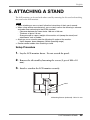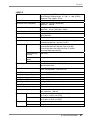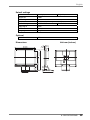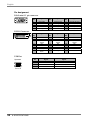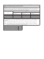
1
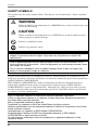
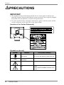
For U.S.A, Canada, etc. (rated 100-120 Vac) Only
FCC Declaration of Conformity
We, the Responsible Party
EIZO NANAO TECHNOLOGIES INC.
5710 Warland Drive, Cypress, CA 90630
Phone: (562) 431-5011
declare that the product
Trade name: EIZO
Model: FlexScan L363T/L353T
is in conformity with Part 15 of the FCC Rules. Operation of this product is subject to the
following two conditions: (1) this device may not cause harmful interference, and (2) this
device must accept any interference received, including interference that may cause undesired
operation.
This equipment has been tested and found to comply with the limits for a Class B digital
device, pursuant to Part 15 of the FCC Rules. These limits are designed to provide
reasonable protection against harmful interference in a residential installation. This
equipment generates, uses, and can radiate radio frequency energy and, if not installed and
used in accordance with the instructions, may cause harmful interference to radio
communications. However, there is no guarantee that interference will not occur in a
particular installation. If this equipment does cause harmful interference to radio or
television reception, which can be determined by turning the equipment off and on, the user
is encouraged to try to correct the interference by one or more of the following measures.
* Reorient or relocate the receiving antenna.
* Increase the separation between the equipment and receiver.
* Connect the equipment into an outlet on a circuit different from that to which the receiver
is connected.
* Consult the dealer or an experienced radio/TV technician for help.
Changes or modifications not expressly approved by the party responsible for compliance
could void the user’s authority to operate the equipment.
Note
Use the attached specified cable below or EIZO signal cable with this monitor so as to keep
interference within the limits of a Class B digital device.
- AC Cord
- Shielded Signal Cable
- Stereo mini-jack cable
Canadian Notice
This Class B digital apparatus complies with Canadian ICES-003.
Cet appareil numérique de le classe B est comforme à la norme NMB-003 du Canada.
User’s Manual
Touch Panel Color LCD Monitor
It shall be assured that the final system is in compliance
to IEC60601-1-1 requirement.
English
SAFETY SYMBOLS
This manual uses the safety symbols below. They denote critical information. Please read them
carefully.
WARNING
Failure to abide by the information in a WARNING may result in serious injury and
can be life threatening.
CAUTION
Failure to abide by the information in a CAUTION may result in moderate injury
and/or property or product damage.
Indicates a prohibited action.
Indicates to ground for safety.
• This product has been adjusted specifically for use in the region to which it was originally
shipped. If operated outside this region, the product may not perform as stated in the
specifications.
• Power supplied equipment can emit electromagnetic waves, that could influence, limit or
result in malfunction of the monitor. Install the equipment in a controlled environment, where
such effects are avoided.
• This is a monitor intended for use in a medical imaging system. It does not support the
display of mammography images for diagnosis.
No part of this manual may be reproduced, stored in a retrieval system, or transmitted, in any
form or by any means, electronic, mechanical, or otherwise, without the prior written permission
of EIZO NANAO CORPORATION.
EIZO NANAO CORPORATION is under no obligation to hold any submitted material or
information confidential unless prior arrangements are made pursuant to EIZO NANAO
CORPORATION's receipt of said information. Although every effort has been made to ensure
that this manual provides up-to-date information, please note that EIZO monitor specifications
are subject to change without notice.
VGA is a registered trademark of International Business Machines Corporation.
VESA is a registered trademark or a trademark of Video Electronics Standards Association in
the United States and other countries.
Mac is a registered trademark of Apple Inc.
TouchWare is a trademark of 3M in the United States and other countries.
Windows and Windows Vista are registered trademarks of Microsoft Corporation in the United
States and other countries.
PowerManager is a trademark of EIZO NANAO COROPRATION.
ScreenManager, FlexScan and EIZO are registered trademarks of EIZO NANAO
CORPORATION in Japan and other countries.
All other company and product names are trademarks or registered trademarks of their
respective owners.
2
English
TABLE OF CONTENTS
PRECAUTIONS ................................................................................... 4
1. INTRODUCTION ..................................................................................... 9
1-1. Features ........................................................................................................9
1-2. Package Contents..........................................................................................9
1-3. Controls & Connectors ..............................................................................10
2. CABLE CONNECTION ......................................................................... 12
2-1. Before connecting .......................................................................................12
2-2. Connecting the signal cable ........................................................................13
2-3. Connecting two PCs to the monitor............................................................15
2-4. Sound Connections .....................................................................................16
3. ScreenManager .................................................................................... 17
3-1. How to use the ScreenManager ..................................................................17
3-2. Adjustments and Settings ............................................................................18
3-3. Useful Functions .........................................................................................19
4. ADJUSTMENT ...................................................................................... 21
4-1. Screen Adjustment ......................................................................................21
4-2. Color Adjustment .......................................................................................25
4-3. Power-save Setup ........................................................................................27
5. ATTACHING A STAND .......................................................................... 29
6. TROUBLESHOOTING........................................................................... 30
7. CLEANING ............................................................................................ 34
8. SPECIFICATIONS ................................................................................. 35
9. GLOSSARY........................................................................................... 41
APPENDIX/ANHANG/ANNEXE .................................................................. i
TABLE OF CONTENTS
3
English
PRECAUTIONS
IMPORTANT!
• This product has been adjusted specifically for use in the region to which it was
originally shipped. If operated outside the region to which it was originally shipped,
the product may not perform as stated in the specifications.
• To ensure personal safety and proper maintenance, please read this section and the
caution statements on the unit (refer to the figure below).
[Location of the Caution Statements]
[Symbols on the unit]
Symbol
4
PRECAUTIONS
Location
This symbol indicates
Front
Control panel
Power button
Press to turn the monitor’s power on or off.
Rear
Name Plate
Alternating current
Rear
Alerting electrical hazard
Rear
Caution
Refer to SAFETY SYMBOLS section in this
manual.
English
WARNING
If the unit begins to emit smoke, smells like something is burning, or
makes strange noises, disconnect all power connections immediately
and contact your dealer for advice.
Attempting to use a malfunctioning unit may result in fire, electric shock, or
equipment damage.
Do not open the cabinet or modify the unit.
Opening the cabinet or modifying the unit may result in fire, electric shock, or
burn.
Refer all servicing to qualified service personnel.
Do not attempt to service this product yourself as opening or removing covers
may result in fire, electric shock, or equipment damage.
Keep small objects or liquids away from the unit.
Small objects accidentally falling through the ventilation slots into the cabinet
or spillage into the cabinet may result in fire, electric shock, or equipment
damage.
If an object or liquid falls/spills into the cabinet, unplug the unit immediately.
Have the unit checked by a qualified service engineer before using it again.
Place the unit at the strong and stable place.
A unit placed on an inadequate surface may fall and result in injury or
equipment damage.
If the unit falls, disconnect the power immediately and ask your dealer for
advice. Do not continue using a damaged unit. Using a damaged unit may
result in fire or electric shock.
SIG.
AUTO
ENT.
OK
Use the unit in an appropriate location.
Not doing so may result in fire, electric shock, or equipment damage.
* Do not place outdoors.
* Do not place in the transportation system (ship, aircraft, trains, automobiles,
etc.)
* Do not place in a dusty or humid environment.
* Do not place in a location where water is splashed on the screen (bathroom,
kitchen, etc.).
* Do not place in a location where the steam comes directly on the screen.
* Do not place near heat generating devices or a humidifier.
* Do not place in an inflammable gas environment.
PRECAUTIONS
5
English
WARNING
To avoid danger of suffocation, keep the plastic packing bags away
from babies and children.
Use the enclosed power cord and connect to the standard power outlet
of your country.
Be sure to remain within the rated voltage of the power cord.
Not doing so may result in fire or electric shock.
Power Supply: 100-120/200-240 Vac 50/60Hz
To disconnect the power cord, grasp the plug firmly and pull.
Tugging on the cord may damage and result in fire or electric shock.
The equipment must be connected to a grounded main outlet.
Failure to do so may result in fire or electric shock.
Use the correct voltage.
* The unit is designed for use with a specific voltage only. Connection to
another voltage than specified in this User’s Manual may cause fire, electric
shock, or equipment damage.
Power Supply: 100-120/200-240 Vac 50/60Hz
* Do not overload your power circuit, as this may result in fire or electric
shock.
Handle the power cord with care.
* Do not place the cord underneath the unit or other heavy objects.
* Do not pull on or tie the cord.
If the power cord becomes damaged, stop using it. Use of a damaged cord
may result in fire or electric shock.
For the electrical safety, do not connect or disconnect the power cord
in the presence of patients.
Never touch the plug and power cord if it begins to thunder.
Touching them may result in electric shock.
When attaching an arm stand, please refer to the user’s manual of the
arm stand and install the unit securely.
Not doing so may cause the unit to become unattached, which may result in
injury or equipment damage. Before installation, make sure that desks, walls,
and others an arm stand is fixed on have adequate mechanical strength. When
the unit is dropped, please ask your dealer for advice. Do not continue using a
damaged unit. Using a damaged unit may result in fire or electric shock. When
reattaching the tilt stand, please use the same screws and tighten them
securely.
6
PRECAUTIONS
OK
English
WARNING
Do not touch a damaged LCD panel directly with bare hands.
The liquid crystal that may leak from the panel is poisonous if it enters the
eyes or mouth.
If any part of the skin or body comes in direct contact with the panel, please
wash thoroughly.
If some physical symptoms result, please consult your doctor.
Fluorescent backlight lamps contain mercury (the products that have
LED backlight lamps contain no mercury), dispose according to local,
state or federal laws.
Exposure to elemental mercury can result in effects on the nervous system,
including tremor, memory loss, and headache.
CAUTION
Handle with care when carrying the unit.
Disconnect the power cord and cables when moving the unit. Moving the unit
with the cord attached is dangerous. It may result in injury.
When handling the unit, grip the bottom of the unit firmly with both
hands ensuring the panel faces outward before lifting.
Dropping the unit may result in injury or equipment damage.
OK
SIG.
AUTO
ENT.
Do not block the ventilation slots on the cabinet.
* Do not place any objects on the ventilation slots.
* Do not install the unit in a closed space.
* Do not use the unit laid down or upside down.
Blocking the ventilation slots prevents proper airflow and may result in fire,
electric shock, or equipment damage.
Do not touch the plug with wet hands.
Doing so may result in electrical shock.
Use an easily accessible power outlet.
This will ensure that you can disconnect the power quickly in case of a
problem.
Periodically clean the area around the plug.
Dust, water, or oil on the plug may result in fire.
Unplug the unit before cleaning it.
Cleaning the unit while it is plugged into a power outlet may result in electric
shock.
PRECAUTIONS
7
English
CAUTION
If you plan to leave the unit unused for an extended period, disconnect
the power cord from the wall socket after turning off the power switch
for the safety and the power conservation.
This product is only suitable for a patient environment, but not for
contact with a patient.
Notice for this monitor
This product is suited to general purposes like creating documents, viewing multimedia content.
Monitors should be set to a lower brightness to reduce changes in luminosity caused by long-term
use and maintain a stable display.
The LCD panel is manufactured using high-precision technology. Although, missing pixels or lit
pixels may appear on the LCD panel, this is not a malfunction. Percentage of effective dots:
99.9994% or higher.
The backlight of the LCD panel has a fixed life span. When the screen becomes dark or begins to
flicker, please contact your dealer.
Do not scratch or press on the panel with any sharp objects, as this may result in damage to the
panel. Do not attempt to brush with tissues as this may scratch the panel.
When the screen image is changed after displaying the same image for extended periods of time,
an afterimage may appear. Use the screen saver or power save function to avoid displaying the
same image for extended periods of time.
When the monitor is cold and brought into a room or the room temperature goes up quickly, dew
condensation may occur on the interior and exterior surfaces of the monitor. In that case, do not
turn the monitor on. Instead wait until the dew condensation disappears, otherwise it may cause
some damage to the monitor.
To use the monitor comfortably
An excessively dark or bright screen may affect your eyes. Adjust the brightness of the monitor
according to the environmental conditions.
Staring at the monitor for a long time tires your eyes. Take a 10-minute rest every hour.
8
PRECAUTIONS
English
1. INTRODUCTION
Thank you very much for choosing an EIZO Color Monitor.
1-1. Features
• Dual inputs compliant
• DVI (p.41) Digital input (TMDS (p.42)) compliant.
• Horizontal scanning frequency:
Vertical scanning frequency:
Resolution:
Analog input 24 - 61 kHz
Digital input 31 - 49 kHz
Analog input 55 - 76 Hz
Digital input 59 - 61 Hz (VGA text: 70 Hz)
0.8 M pixels (1024 dots x 768 lines)
• Auto Adjustment compliant
• Support to sRGB (p.42) standard
• Built-in speaker system
• Touch Panel provided
• Touch Panel Pointer “TP1” is available (optional, p.15)
1-2. Package Contents
Please contact your local dealer for assistance if any of the listed items are missing or
damaged.
• LCD Monitor
• Power Cord
• Signal Cable (MD-C87)
• USB Cable (MD-C93)
• Stereo mini-jack Cable
• User’s Manual
• ScreenManager Quick Reference
• LIMITED WARRANTY
• Mounting Screws: M4 x 12 (mm) x 4 pcs
• EIZO Touch Panel Disk (CD-ROM)
(Contents: touch panel drivers TouchWare (for Windows 2000/XP) and MT 7 (for
Windows Vista), and Installation Guides)
NOTE
• Please retain the packing materials for future transference.
• Regarding installing touch panel drivers and cautions, please refer to the Installation
Guides in the CD-ROM.
1. INTRODUCTION
9
English
1-3. Controls & Connectors
Front
(1)
(2)
SIG.
AUTO
ENT.
Control Panel
SIG.
AUTO
ENT.
(3) (4) (5)
(1)
(2)
Press the Right and Left Buttons.
Mute
Press the Up or Down Button for a while after
pressing the Right or Left Button to display the
volume control bar.
Press the Right or Left Button to mute off.
SIG.
Input Signal Selection Button
(4)
AUTO
Auto Adjustment Button
(5)
ENT.
Enter Button
Control Buttons (Left, Down, Up, Right)
(7)
Power Switch
(8)
Power Indicator*2
*2
(8)
Volume Control
(3)
*1
(7)
ScreenManager®
Speaker*1
(6)
10
(6)
Blue
Operation
Yellow /
Flashing yellow
(2 times for each)
Power saving
Flashing yellow slowly
Power off
Regarding the sound connection, see page 16.
Regarding the power indicator for the off timer, see page 19.
1. INTRODUCTION
English
Rear
(15)
POWER INPUT
DVI
D-SUB
(14)
(16)
Bottom
(9)
(10) (11)
(12)
(13)
(9)
Power Connector
(10)
(11)
USB Port (Upstream)
External line in (stereo mini-jack)
(12)
DVI-D Connector (SIGNAL 1)
(13)
D-Sub mini 15 pin Connector (SIGNAL 2)
(14)
Security Lock Slot*3
(15) 4 Holes for Mounting a stand *4
(16) Stand (Detachable) *4
*3
*4
Allows for connection of a security cable. This lock supports Kensington’s
MicroSaver security system.
The LCD monitor can be used with an other stand by removing the stand (see page
29).
1. INTRODUCTION
11
English
2. CABLE CONNECTION
2-1. Before connecting
Before connecting your monitor to the PC, change the display screen settings (resolution
(p.42) and frequency) in accordance with the charts below.
NOTE
• The lower display modes like 640x 480, automatically enlarge to the maximum
display mode (1024 x 768), and some lines of the characters may become fuzzy. In
this case, use <Smoothing> function (p.23) to make the lines clear.
• When your computer and display support VESA DDC, the suitable resolution and
the refresh rate are set by just plugging your display into the computer without any
manual settings.
Analog Input
Resolution
Frequency
Dot Clock
Remarks
320 x 200
640 x 480
720 x 400
800 x 600
1024 x 768
70 Hz
~75 Hz
70 Hz
~75 Hz
~75 Hz
79 MHz
(Max)
VGA Mode13
VGA, VESA
VGA TEXT
VESA
VESA
Resolution
Frequency
Dot Clock
Remarks
640 x 480
720 x 400
800 x 600
1024 x 768
60 Hz
70 Hz
60 Hz
60 Hz
66 MHz
(Max)
VGA
VGA TEXT
VESA
VESA
Digital Input
12
2. CABLE CONNECTION
English
2-2. Connecting the signal cable
NOTE
• Be sure that the power switches of both the PC and the monitor are OFF.
1.
Plug the signal cable into the connector at the rear of the monitor
and the other end of the cable into the video connector on the PC.
After connecting, secure the connection with the screw-in fasteners.
Digital Signal
Input Connecter
Analog Signal
Input Connecter
2. Power Cord
5. USB Cable
1. Signal Cable
Analog Input
Signal Cable
Signal Cable (enclosed, MDC87)
Connector of PC
Video Output
Connector/ D-Sub
mini 15 pin
Input Connecor
(monitor)/ D-Sub
mini 15 pin
PC
• Standard graphics card
Digital Input
Signal Cable
FD-C39 (Optional)
Connector of PC
Video Output
Connector DVI-I
Input Connecor
(monitor)/ DVI
PC
• Digital Graphics card
2. CABLE CONNECTION
13
English
2.
Plug the power cord into the power connector on the rear of the
monitor. Then, plug the other end of the cord into a power outlet.
WARNING
Use the enclosed power cord and connect to the standard
power outlet of your country.
Be sure to remain within the rated voltage of the power cord.
Not doing so may cause in fire or electric shock.
The equipment must be connected to a grounded main
outlet.
Not doing so may cause in fire or electric shock.
3.
Turn on the monitor’s main power and then switch on the PC's
power.
The monitor’s power indicator will light up (blue).
If an image does not appear, refer to the “6. TROUBLESHOOTING” (p.30) for
advice.
Turn on the monitor’s main power and then switch on the PC's power.
4.
Install the touch panel driver TouchWare (for Windows 2000/XP) or
MT 7 (for Windows Vista) depending on your OS.
NOTE
• Regarding installing touch panel drivers and cautions, please refer to the
Installation Guides in the CD-ROM.
5.
Connect the upstream port of the monitor to the downstream port of
the USB compliant by using the USB cable.
After connecting the USB cable, the USB function can be set up automatically.
14
2. CABLE CONNECTION
English
NOTE
• Whenever finished, turn off the PC and the monitor. Touch operation is effective
until turning off both PC and monitor.
• Adjust brightness of the screen depending on the brightness of your environment.
Too dark or too bright of a screen can cause eyestrain.
• Be sure to take adequate rests. A 10-minute rest period each hour is suggested.
• For the users with gloves, we recommend to use touch panel pointer, “TP1”
(optional). Regarding the installation, please refer to the User’s Manual of TP1.
2-3. Connecting two PCs to the monitor
Two PCs can be connected to the monitor through the DVI and the D-Sub mini 15 pin
connector on the back of the monitor.
Selecting the active input
The Input Signal Selection Button on the control panel can be used to select either Signal
1 or Signal 2 as the active input at any time. Every time the button is pressed, the input
changes. When switching the signal, the kind of the input signal (Signal1 or 2/Analog or
Digital) is displayed for a few seconds on the right top corner of the screen.
Input Signal Selection Button
SIG.
AUTO
ENT.
2. CABLE CONNECTION
15
English
2-4. Sound Connections
NOTE
• Always switch the monitor and audio devices or computers off whenever connecting
or disconnecting any audio devices (computer or CD player) to the monitor.
• Use the enclosed stereo mini-jack cable for connecting audio devices or computers
to the monitor.
• The touch sound may not be output from the external line out of the PC depending
on the hardware configuration.
1.
Connect the stereo mini-jack cable to the external line in of the
monitor.
2.
Connect the other side of stereo mini-jack cable to the line out of
audio devices.
POWER INPUT
DVI
D-SUB
Computer or
CD Player
Volume control
Volume control
Mute
Mute off
Press the Right and Left Buttons.
Press the Up or Down Button for a while after pressing the Right or Left
Button to display the volume control bar.
Press the Right or Left Button.
NOTE
• <Sound> menu of the ScreenManager also controls the sound.
16
2. CABLE CONNECTION
English
3. ScreenManager
3-1. How to use the ScreenManager
ScreenManager
Main Menu
Control Buttons
Left, Down, Up, Right
SIG.
AUTO
SIG.
ENT.
AUTO
ENT.
Auto Adjustment Button Enter Button
1.
Entering the ScreenManager
Press the Enter Button once to display the main menu of the ScreenManager.
2.
Making Adjustments and Settings
(1) Select the desired sub menu icon using the Control Buttons and press the Enter
Button. The sub menu appears.
(2) Use the Control Buttons to select the desired setting icon and press the Enter
Button. The setting menu appears.
(3) Use the Control Buttons to make all required adjustments and press the Enter
Button to save the settings.
3.
Exiting the ScreenManager
(1) To return to the main menu, select the <Return> icon or press the Down
Button twice, followed by the Enter Button.
(2) To exit the ScreenManager, select <Exit> icon or press the Down Button twice,
followed by the Enter Button.
NOTE
• Double clicking the Enter Button at any time also exits the ScreenManager menu.
3. ScreenManager
17
English
3-2. Adjustments and Settings
The following table shows all the ScreenManager’s adjustment and setting menus.
“*” indicates adjustments of analog input only and “**” indicates digital input only.
Main menu
Screen
Sub menu
Reference
Clock
*
Phase
*
Position
*
Range Adjustment
*
4-1. Screen Adjustment (p.21)
Smoothing
Color
Brightness
4-2. Color Adjustment (p.25)
Color Mode
• Custom
Temperature
Gamma
Saturation
Hue
Gain
Reset
• sRGB
Sound
Volume
Control the sound volume.
Mute
PowerManager
Mute the sound.
DVI DMPM
**
VESA DPMS
*
4-3. Power-save Setup (p.27)
Sound
Others
*1
18
Input Signal
Set the input signal selection of
automatic or manual (p.20)
Off Timer
Set the power save (p.19)
VGA Selection
Select the display mode. (p.31)
Menu Position
Adjust the menu position.
Translucent
Set the transparency of the menu.
Menu Off Timer
Set the menu displaying time.
Reset
Return to the factory default settings.
(p.39)
Information
Information
Review the ScreenManager’s settings,
model name, serial number and usage
time*1.
Language
English, German,
French, Spanish,
Italian and Swedish
Select the ScreenManager’s language.
Due to the inspection on the factory, the usage time may not “0 hour” at shipping.
3. ScreenManager
English
3-3. Useful Functions
Adjustment Lock
Use the “Adjustment Lock” function to prevent any accidental changes.
Locked function
• Auto Adjustment Button adjustments and settings in the
ScreenManager.
Unlocked function
• Adjustment of brightness by the Control Buttons.
• Sound control by the Control Buttons.
• Input Signal Selection Button
[To lock]
(1) Switch off the monitor’s power by the power switch on the control panel.
(2) Press on the Auto adjustment button while switching on the monitor’s power.
[To unlock]
(1) Switch off the monitor’s power by the power switch on the control panel.
(2) Hold down the Auto adjustment button once again and turn the power back on.
Off Timer
The off timer function causes the monitor to automatically enter a power off state after
a predetermined amount of time has lapsed. This function was created to reduce
afterimage characteristics that are particular to LCD monitors when the monitor screen
is left on for a long period without use.
[Procedure]
(1) Select <Off Timer> in the ScreenManager <Others> menu.
(2) Select “Enable” and press the Right and Left Buttons to adjust the “On Period” (1
to 23 hours).
[Off timer system]
PC
Monitor
Power Indicator
On Period (1H - 23H)
Operation
Blue
Last 15 min. in “On period”
Advance Notice *1
Blue Flashing
“On period” expired
Power off
Flashing yellow slowly
*1
Advance notice (Power Indicator flashing blue) will be given 15 minutes before the monitor
automatically enters the “Power Off” mode. To delay entering the “Power Off” mode, press
the power switch during the advance notice period. The monitor will continue to operate for
an additional 90 minutes.
[Power Resumption Procedure]
Press the power switch.
NOTE
• The off timer function works while the PowerManager is active, but there is no
advance notice before the monitor’s power is switched off.
3. ScreenManager
19
English
EIZO Logo disappearing function
When switching on the Power Switch on the control panel, the EIZO logo is displyed
for a while. If you desire to display or undisplay this logo, use this function. (Default is
logo appearing.)
[To undisplay]
(1) Switch off the monitor’s power by the Power switch on the control panel.
(2) Hold down the Enter button once again and turn the power back on.
[To display again]
(1) Switch off the monitor’s power by the Power switch.
(2) Hold down the Enter button once again and turn the power back on.
Automatically selecting the input signal function
The monitor will automatically detect the inputted signal of either the connection for
display.
Connecting two PCs to the monitor
When the one computer is switched off or entering the power saving mode, the monitor
will automatically dislay the other signal.
Use the ScreenManager to switch the input selection to manual.
[Procedure]
(1) Select <Input Signal> in the <Others> menu.
(2) Select “Manual”.
20
3. ScreenManager
English
4. ADJUSTMENT
The monitor displays the digital input image correctly based on its pre-setting
data. Adjust the brightness (p.24).
4-1. Screen Adjustment
Screen adjustments for the LCD monitor should be used in suppressing screen flickering
and also for adjusting the screen to its proper position. There is only one correct
position for each display mode. It is also recommended to use the ScreenManager
function when first installing the display or whenever changing the system.
Adjustment Procedure
NOTE
• Allow the LCD monitor to stabilize for at least 20 minutes before making image
adjustments.
1.
Press the Auto Adjustment Button on the control panel.
The message “Your setting will be lost, if you press again now.” appears and
remains on the screen for 5 seconds. While the message is on the screen, press the
Auto Adjustment Button again to automatically adjust the clock, phase, and screen
position. If you do not wish to do adjust the screen, do not press the Auto
Adjustment Button again.
NOTE
• The Auto Adjustment function is intended for use on AT-compatible PC running
Windows. It may not work properly in either of the following cases.
When running an AT-compatible PC on MS-DOS (Not windows). The
background color for the “wall paper” or “desktop” pattern is set to black.
If the appropriate screen can not be made by using the Auto Adjustment
Button, adjust the screen through the following procedures. If the
appropriate screen can be made, proceed to step 4.
4. ADJUSTMENT
21
English
2.
We recommend setting the desktop pattern to that as shown in the
diagram below.
NOTE
• More precise adjustment is available for using the “Screen Adjustment
program” utility software. It can be downloaded from the EIZO homepage
(http://www.eizo.com/).
3.
Adjust by using <Screen> menu in the ScreenManager.
(1) Vertical bars appear on the screen
→
Use the <Clock> (p.41) adjustment.
Select the <Clock> and eliminate the vertical bars by using the Right and Left
of the Control Buttons.
Do not continuously press the Control Buttons, as the adjustment value will
change quickly and make it difficult to locate the most suitable adjustment
point. If the horizontal flickering, blur or bars appear, proceed to <Phase>
adjustment as follows.
(2) Horizontal bars appear on the screen.
Use the <Phase> (p.42) adjustment.
→
Select the <Phase> and eliminate the horizontal flickering, blurring or bars by
using the Right and Left Buttons.
NOTE
• Horizontal bars may not completely disappear from the screen depending on
the PC.
22
4. ADJUSTMENT
English
(3) The screen position is incorrect.
→
Use the <Position> adjustment.
The correct displayed position of the monitor is decided because the number
and the position of the pixels are fixed. The “Position” adjustment moves the
image to the correct position.
Select <Position> and adjust the position by using the Up, Down, Right and
Left Buttons.
If vertical bars of distortion appear after finishing the <Position> adjustment,
return to <Clock> adjustment and repeat the previously explained adjustment
procedure. Clock→ Phase→ Position
4.
To adjust the output signal range (Dynamic Range) of the signal.
→
Use the <Range Adjustment> (p.42) of <Screen> menu.
This controls the level of output signal range to display the whole color gradation
(256 colors).
[Procedure]
Press the Auto Adjustment Button on the control panel while displaying the
<Range Adjustment> menu to automatically adjust the range. The screen blanks
for a moment, and adjusts the color range to display the whole color gradation of
the current output signal.
5.
To smooth the blurred texts of the enlarged screen of the lower
resolutions.
Switch the <Smoothing> setting.
→
<Smoothing> is clear-cut the letters or lines.
Select <Smoothing> in the screen menu and select the suitable level from 1 ~ 5.
NOTE
• The “Smoothing” is disabled in the resolution 1024 x 768.
• Since the displayed image is enlarged, the blurred texts may not be
necessarily lost completely.
4. ADJUSTMENT
23
English
6.
To Set the Brightness of the screen.
Use the <Brightness> adjustment.
→
The brightness of the entire screen is controlled by changing the brightness of the
backlight.
Select < Brightness > in the screen menu and adjust by using the Up and Down
Buttons.
NOTE
• Directly pressing the Up and Down Buttons also adjusts the brightness. Press
the Enter Button to save and exit the settings after the adjustment.
24
4. ADJUSTMENT
English
4-2. Color Adjustment
The <Color> menu in the ScreenManager enables to change the color of the screen. By
using the <Color Mode>, the adjustment mode can be selected from <Custom mode> (to
adjust the color settings according to your preference) and <sRGB> mode.
In the analog input, perform the “Range Adjustment” (p.23) before making the
color adjustments.
NOTE
• Allow the LCD monitor to stabilize for at least 20 minutes before making image
adjustments. (Allow the monitor to warm up for at least 20 minutes before making
adjustments.)
• Performing the <Reset> of the <Color> menu returns the color settings to the
default settings
• The values shown in percentages represent the current level within the specific
adjustment. They are available only as a reference tool. (To create an uniform white
or black screen, the percentages for each will probably not be the same.)
Adjustment Contents
Menu
Color Mode
Custom
sRGB
Function Descriptions
Adjustable range
Brightness
√
√
To set the brightness of the
screen
0 ∼ 100%
Temperature
(p.41)
√
-
To set the color temperature
4,000 ∼ 10,000 K
in 500 K increments
(including 9,300 K).
Default setting is off
(normal white)
NOTE
• The values shown in the Kelvin are available only as a
reference tool.
• Setting the temperature under 4,000 K or over 10,000
K invalidates the color temperature setting. (The color
temperature’s setting turns “OFF”.)
Gamma
(p.41)
√
-
To set the gamma value
1.8 ∼ 2.6
NOTE
• If setting the gamma value, the using the monitor in
the digital signal input is recommended.
If using the monitor in the analog input signal, set the
gamma value from 1.8 to 2.2.
4. ADJUSTMENT
25
English
Menu
Saturation
Color Mode
Custom
sRGB
√
-
Function Descriptions
To change the saturation
Adjustable range
-128 ∼ 127
Setting the minimum
level (-128) turns the
image to the
monochrome.
NOTE
• The <Saturation> adjustment may cause
undisplayable color tone.
Hue
√
-
To change the flesh color,
etc.
-32 ∼ 32
NOTE
• The <Hue> adjustment may cause undisplayable color
tone.
Gain (p.41)
√
-
To change each color (red,
green and blue)
0 ∼ 100%
By adjusting the red,
green and blue color
tones for each mode,
custom colors can be
defined. Display a
white or gray
background image and
adjust the <Gain>.
NOTE
• The values shown in the percentage are available only
as a reference tool.
• Setting the <Temperature> (p.41) invalidates the
<Gain> adjustment. <Gain> setting returns to the
default.
Reset
26
4. ADJUSTMENT
√
-
To return the color settings
to the default settings
Select the “Reset”.
English
4-3. Power-save Setup
The <PowerManager> menu in the ScreenManager enables to set the power-save setup.
NOTE
• Do your part to conserve energy, turn off the monitor when you are finished using it.
Disconnecting the monitor from the power supply is recommended to save energy
completely.
Analog Input
This monitor complies with the VESA DPMS (p.42).
[Procedure]
(1) Set the PC’s power saving settings.
(2) Select “VESA DPMS” from the <PowerManager> menu.
[Power saving system]
PC
Operation
STAND-BY
SUSPEND
OFF
Power saving
Monitor
Power Indicator
Operation
Blue
Power saving
Yellow
[Power Resumption Procedure]
Operate the mouse or keyboard to return to a normal screen.
Digital Input
This monitor complies with the DVI DMPM (p.41).
[Procedure]
(1) Set the PC’s power saving settings.
(2) Select “DVI DMPM” from the < PowerManager > menu.
[Power saving system]
*1
PC
Monitor
Operation
Power saving
Operation
Power saving
Power Indicator
Blue
Yellow
Flashing yellow
Off mode
Power saving*1
(2 times for each)
Power saving through the PC’s off mode is only supported when “Manual” is selected on
the ScreenManager’s <Input Signal>.
[Power Resumption Procedure]
Operate the mouse or keyboard to return to a normal screen from the Power save mode
of the PC.
Power on the PC to return a normal screen from the Off mode of the PC.
4. ADJUSTMENT
27
English
Power save for speaker
When the monitor is in the power-saving mode, sound of speaker also erases
simultaneously can be performed.
[Procedure]
(1) Set the PC’s power saving settings.
(2) Select <Sound>.
(3) Select “Disable”. (“Enable” is selected to leave sound.)
28
4. ADJUSTMENT
English
5. ATTACHING A STAND
The LCD monitor can be used with other stand by removing the tilt stand and attaching
the stand to the LCD monitor.
NOTE
• When attaching an arm or stand, follow the instructions of their user’s manual.
• When using another manufacturer’s arm or stand, confirm the following in advance
and select one conforming to the VESA standard.
- Clearance between the screw holes: 100 mm x 100 mm
- Thickness of plate: 2.6 mm
- Strong enough to support weight of the monitor unit (except the stand) and
attachments such as cables.
• Attach an arm or stand to meet the following tilt angles of the monitor.
- Up 45 degrees, down 0 degrees (Within operating range)
• Please connect cables after attaching a stand.
Setup Procedure
1.
Lay the LCD monitor down. Do not scratch the panel.
2.
Remove the tilt stand by loosening the screws (2 pcs of M4 x 10
mm).
3.
Attach a stand to the LCD monitor securely.
stand
4 Mounting Screws (enclosed): M4 x 12 mm
5. ATTACHING A STAND
29
English
6. TROUBLESHOOTING
If a problem persists even after applying the suggested remedies, contact an EIZO dealer.
• No picture problems : See No.1 ~ No.2
• Imaging problems : See No.3 ~ No.9
• Other problems : See No.10 ~ No.13
• Touch Panel Problems: See No. 14 ~ No.17
Problems
1. No picture
• Indicator status: Off
Points to check with possible solutions
Check that the power cord is correctly
connected. If the problem persists, turn off the
monitor power for a few minutes, then turn it
back on and try again.
• Indicator status: Blue
Check the “Brightness” setting.
Switch the signal input by pressing the Input
Signal Selection Button on the front control
panel.
• Indicator status: Yellow
Try pressing a key on the keyboard, or clicking
the mouse. (p.27)
• Indicator status: Flashing Yellow
(twice for each)
Try pressing the power of the computer.
These message appear when the signal is not
inputted correctly, even if the monitor functions
• This message appears when no signal
properly.
is input. (This is displayed for about
When the image is displayed correctly after a
40 seconds.)
short time, there is no problem with the
monitor. (Some PCs do not output the signal
soon after powering on.)
Check that the PC is turned ON.
Check that the signal cable is properly
connected to the PC or graphics board.
Switch the signal input by pressing the Input
Signal Selection Button on the front control
panel.
2.
The message below appears.
• The signal frequency is out of range.
Error signal frequency will be
displayed in red.
30
6. TROUBLESHOOTING
Use the graphics board’s utility software to
change the frequency setting. (Refer to the
manual of the graphics board.)
English
Problems
Points to check with possible solutions
3. Display position is incorrect.
Adjust the image position using the <Position>
(p.23)
The two display modes, VGA 720 x 400 (70
Hz) and 320 x 200 (70 Hz), have the same
signal timings. Using this adjustment selects the
appropriate display mode. (This function effects
only when the resolution is VGA 720 x 400 (70
Hz) or 320 x 200 (70 Hz).)
If the problem persists, use the graphics board’s
utility software to change the display position if
available.
4. Vertical bars of distortion appear.
Decrease the vertical bars using the <Clock>.
(p.22)
5. Horizontal bars of distortion
appear.
Decrease the horizontal bars using the <Phase>.
(p.22)
6. Letters and lines appear blurred.
Switch the <Smoothing> mode. (p.23)
7. The screen is too bright or too
dark.
Adjust the <Brightness> . (The backlight of the
LCD monitor has a fixed life span. When the
screen becomes dark or begins to flicker, please
consult your dealer.)
8. Afterimages appear.
Do you use the screen saver or timer when
displaying the same image for extended periods
of time? (p.19)
Afterimages are particular to LCD monitors.
Avoid displaying the same image for extended
periods of time.
9. The screen has defective pixels
(e.g. slightly light or dark).
This is due to the characteristics of the panel
itself, and not the LCD product.
6. TROUBLESHOOTING
31
English
Problems
Points to check with possible solutions
10.The <Smoothing> cannot be
selected.
<Smoothing> is disabled when the screen is
displayed in the 1024 x768.
11.The Main menu of ScreenManager
does not operate.
The adjustment lock is probably on. To unlock:
switch the LCD monitor off. Then, while
pressing the Auto Adjustment Button switch,
the power on. (p.19)
12.The Auto Adjustment Button does
not operate.
The adjustment lock is probably on. To unlock:
switch the LCD monitor off. Then, while
pressing the Auto Adjustment Button switch,
the power on. (p.19)
The Auto sizing function is intended for use on
the AT-compatible PC running Windows. It may
not work properly in either of the following
cases.
• When running an AT-compatible PC on MSDOS (Not windows).
• The background color for the “wall paper”
or “desktop” pattern is set to black.
Some signals from a graphics board may not
function properly.
13.The signal Selection Button does
not operate.
32
6. TROUBLESHOOTING
The computer with digital may be in the off
mode (power indicator flashing yellow). Try to
press the monitor’s power switch and press the
Input Signal Selection Button again.
English
•
Touch Panel problems
Problems
Points to check with possible solutions
14.Cursor is jittery. / Drawing lines
are not straight and smooth.
The influence of metal may cause jittery cursor.
When multiple monitors are placed close to
each other, leave space between monitors.
15.Cursor position is not correct. /
Cursor jumps.
When cursor position is incorrect or cursor
jumps, turn off and on the monitor. If the
symptom is not improved, perform the
calibration on the monitor.
• Do not touch the screen while turning on the
PC and the monitor. Touch the screen five
seconds later after appearing the image.
• Touch the screen five seconds later after
connecting the USB cable.
• Changing the position or angle of the
monitor will cause cursor jump.
The drawing touch and dragging the fi nger on
the touch panel to draw the picture may cause
incorrect cursor position.
Keep metals away from the panel surface.
Touch with one finger only. Keep other fingers
away from the touch screen. Do not rest the
hand in the monitor or bezel while touching the
screen.
The spray for preventing static electricity may
infl uences the sensibility of the touch panel. Do
not use it on cleaning.
16.Touch operation is effective after
turning off the monitor.
Touch operation is effective until turning off
both PC and monitor.
17.No touch sound.
The touch sound may not be output from the
external line out of the PC depending on the
hardware configuration.
6. TROUBLESHOOTING
33
English
7. CLEANING
Periodic cleaning is recommended to keep the monitor looking new and to prolong its
operation lifetime.
NOTE
• Chemicals such as alcohol and antiseptic solution may cause gloss variation,
tarnishing, and fading of the cabinet or panel, and also quality deterioration of the
image.
• Never use any thinner, benzene, wax, and abrasive cleaner, which may damage the
cabinet or panel.
• Do not allow liquid to enter the clearance between the panel and the panel frame.
• The optional ScreenCleaner is recommended for cleaning the panel surface.
If necessary, the stains on the cabinet and panel surface can be removed by moistening
part of a soft cloth with water.
34
7. CLEANING
English
8. SPECIFICATIONS
L363T-C
LCD Panel
38 cm (15.0 inch), TFT color LCD panel with Anti-Glare
Hard Coating, Viewing Angle: H: 170°, V: 170° (CR≥10)
Response Time: approx. 55 ms
Dot Pitch
0.297 mm
Horizontal Scan Frequency
Analog: 24 ~ 61 kHz (Automatic)
Digital: 31 ~ 49 kHz
Vertical Scan Frequency
Analog: 55 ~ 76 Hz (Automatic)
Digital: 59 ~ 61 Hz, (VGA Text : 70Hz)
Resolution
0.8 M pixels (1024 dots x 768 lines)
Dot Clock (Max.)
Analog: 79 MHz
Digital: 66 MHz
Display Colors
16 million colors (max.)
Display Area
304.1 mm (H) ×228.1 mm (V) (11.9” (H) x 8.9” (V))
(Viewable image size: 381 mm (15.0”))
Touch Panel OS
Microsoft Windows 2000 Service Pack 4
Microsoft Windows XP Service Pack 3 (32 bit)
Microsoft Windows Vista Service Pack 1 (32 bit)
(Not compatible with MacOS)
Communication
protocol
USB serial
Communication
speed
Full speed
Detective method Analog capacitive technology, finger touch
Power Supply
100-120/200-240 VAC±10%, 50/60 Hz,
0.7-0.6 A/0.4-0.35 A
Power Consumption
Max.: 40 W (with speaker)
Power Saving Mode: Less than 2 W
Input Connector
D-Sub mini 15 pin, DVI-D
Analog Input Signal (Sync)
Separate, TTL, Positive/Negative
Analog Input Signal (Video)
0.7Vp-p/75Ω Positive
Input Signal (Digital)
TMDS (Single Link)
Signal registration
Analog: 45 (Factory preset: 12)
Plug & Play
VESA DDC 2B
Amplifier Output (max.)
1W+1W
Line input
Input impeadance 11 kΩ (min.)
Input sensitivity: 500 mV
Dimensions
Weight
with stand
346 mm (W) x 369 mm (H) x 157 mm (D)
(13.4”(W) x 14.5”(H) x 6.2”(D))
without stand
346 mm (W) x 301 mm (H) x 54.5 mm (D)
(13.4”(W) x 11.6”(H) x 1.9”(D))
with stand
5.0 kg (11.2 lbs.)
without stand
4.1 kg (9.0 lbs.)
8. SPECIFICATIONS
35
English
Environment
conditions
Temperature
Operating: 0 °C ~ 35 °C (32 °F ~ 95 ° F)
Transportation/Storage: -20 °C ~ 60 °C (-4 °F ~ 140 ° F)
Humidity
30% to 80% R.H. Non-condensing
Pressure
860 to 1,060 hPa
Certifications and Standards
100-120 VAC
200-240 VAC
Classification of Equipment
36
8. SPECIFICATIONS
CB, NRTL/C-TÜV, FCC-B
CE(93/42/EEC), CB, TÜV Rheinland/GM
Type of protection against electric shock : Class I
EMC class : EN60601-1-2:2007 Group1 Class B
Classification of medical device (MDD 93/42/EEC) : Class I
Mode of operation : Continuous
IP Class : IPX0
English
L353T-C
LCD Panel
38 cm (15.0 inch), TFT color LCD panel with Anti-Glare
Hard Coating, Viewing Angle: H: 150°, V: 160° (CR≥5)
Response Time: approx. 25 ms
Dot Pitch
0.297 mm
Horizontal Scan Frequency
Analog: 24 ~ 61 kHz (Automatic)
Digital: 31 ~ 49 kHz
Vertical Scan Frequency
Analog: 55 ~ 76 Hz (Automatic)
Digital: 59 ~ 61 Hz, (VGA Text : 70Hz)
Resolution
0.8 M pixels (1024 dots x 768 lines)
Dot Clock (Max.)
Analog: 79 MHz
Digital: 66 MHz
Display Colors
16 million colors (max.)
Display Area
304.1 mm (H) ×228.1 mm (V) (11.9” (H) x 8.9” (V))
(Viewable image size: 381 mm (15.0”))
Touch Panel OS
Microsoft Windows 2000 Service Pack 4
Microsoft Windows XP Service Pack 3 (32 bit)
Microsoft Windows Vista Service Pack 1 (32 bit)
(Not compatible with MacOS)
Communication
protocol
USB serial
Communication
speed
Full speed
Detective method Analog capacitive technology, finger touch
Power Supply
100-120/200-240 VAC±10%, 50/60 Hz,
0.6-0.5 A/0.35-0.3 A
Power Consumption
Max.: 35 W (with speaker)
Power Saving Mode: Less than 2 W
Input Connector
D-Sub mini 15 pin, DVI-D
Analog Input Signal (Sync)
Separate, TTL, Positive/Negative
Analog Input Signal (Video)
0.7Vp-p/75Ω Positive
Input Signal (Digital)
TMDS (Single Link)
Signal registration
Analog: 45 (Factory preset: 12)
Plug & Play
VESA DDC 2B
Amplifier Output (max.)
1W+1W
Line input
Input impeadance 11 kΩ (min.)
Input sensitivity: 500 mV
Dimensions
Weight
with stand
346 mm (W) x 369 mm (H) x 157 mm (D)
(13.4”(W) x 14.5”(H) x 6.2”(D))
without stand
346 mm (W) x 301 mm (H) x 54.5 mm (D)
(13.4”(W) x 11.6”(H) x 1.9”(D))
with stand
5.0 kg (11.2 lbs.)
without stand
4.1 kg (9.0 lbs.)
8. SPECIFICATIONS
37
English
Environment
conditions
Temperature
Operating: 0 °C ~ 35 °C (32 °F ~ 95 ° F)
Transportation/Storage: -20 °C ~ 60 °C (-4 °F ~ 140 ° F)
Humidity
30% to 80% R.H. Non-condensing
Pressure
860 to 1,060 hPa
Certifications and Standards
100-120 VAC
200-240 VAC
Classification of Equipment
38
8. SPECIFICATIONS
CB, NRTL/C-TÜV, FCC-B
CE(93/42/EEC), CB, TÜV Rheinland/GM
Type of protection against electric shock : Class I
EMC class : EN60601-1-2:2007 Group1 Class B
Classification of medical device (MDD 93/42/EEC) : Class I
Mode of operation : Continuous
IP Class : IPX0
English
Default settings
Analog input
Brightness
100%
Smoothing
3
Digital input
Temperature
Off (normal white: approx. 6500 K)
PowerManager
VESA DPMS
Input Signal
Auto
Off Timer
Disable
Language
English
DVI DMPM
Optional
Touch Panel Pointer
TP1
Dimensions
Unit mm (inches)
3 30 54.5
32.7
(2.15)
(1.29)
369 (14.5)
68 (2.7)
120 (4.7)
235 (9.3)
230 (9.1)
346 (13.6)
306 (12.0)
135 (5.3)
23.3 1
(0.9) (0.04)
157 (6.2)
8. SPECIFICATIONS
39
English
Pin Assignment
D-Sub mini 15 pin connector
3
4
5
10
15
9
1
2
8
7
6
14 13 12 11
Pin
No.
1
2
3
4
5
Signal
Red video
Green video
Blue video
Ground
No pin
Pin
No.
6
7
8
9
10
Signal
Red ground
Green ground
Blue ground
No pin
Ground Shorted
Pin
No.
11
12
13
14
15
Signal
Ground Shorted
Data (SDA)
H. Sync
V. Sync
Clock (SCL)
DVI-D Connector
1 2 3 4 5 6 7 8
9 10 11 12 13 14 15 16
17 18 19 20 21 22 23 24
Pin
No.
1
2
3
4
5
6
7
8
Signal
TMDS Data2TMDS Data2+
TMDS Data2/4
Shield
NC*
NC
DDC Clock (SCL)
DDC Data (SDA)
Analog Vertical
Sync
Pin
No.
9
10
11
12
13
14
15
16
Signal
TMDS Data1TMDS Data1+
TMDS Data1/3
Shield
NC
NC
+5V Power
Ground (For +5V)
Hot Plug Detect
Pin
No.
17
18
19
Signal
TMDS Data0TMDS Data0+
TMDS Data0/5
Shield
NC
NC
TMDS Clock shield
TMDS Clock+
TMDS Clock-
20
21
22
23
24
(*NC: No Connection)
USB Port
Upstream
Series B
40
8. SPECIFICATIONS
No.
1
2
3
4
Signal
VCC
- Data
+ Data
Ground
Signal
Cable power
Serial data
Serial data
Cable Ground
English
9. GLOSSARY
Clock
With the analog input signal display, the analog signal is converted to a digital signal
by the LCD circuitry. To convert the signal correctly, the LCD monitor needs to
produce the same number clock pulse as the dot clock of the graphics system. When
the clock pulse is not correctly set, some vertical bars of distortion are displayed on
the screen.
Color Temperature (Temperature)
Color Temperature is a method to measure the white color tone, generally indicated
in degrees Kelvin. At high temperatures the white tone appears somewhat blue, while
at lower temperatures it appears somewhat red. Computer monitors generally give
best performance at high temperature settings.
5,000 K: Slightly reddish white.
6,500 K: Warm-white tone, similar to white paper or daylight.
9,300 K: Slightly bluish white.
DVI
(Digital Visual Interface)
A digital flat panel interface. DVI can transmit digital data from the PC directly
without loss with the signal transition method “TMDS”.
There are two kinds of DVI connectors. One is DVI-D connector for digital signal
input only. The other is DVI-I connector for both digital and analog signal inputs.
DVI DMPM
(DVI Digital Monitor Power Management)
The Power management system for the digital interface. The “Monitor ON” status
(operation mode) and the “Active Off” status (power-saving mode) are indispensable
for the DVI-DMPM as the monitor’s power mode.
Gain Adjustment
Adjusts each color parameter for red, green and blue. The color of the LCD monitor
is displayed through the color filter of the LCD panel. Red, green and blue are the
three primary colors. The colors on the monitor are displayed by combining these
three colors. The color tone can change by adjusting the illumination amount passed
through each color’s filter.
Gamma
Generally, the relationship that the light intensity values of a monitor change
nonlinearly to the input signal level is called “Gamma Characteristic”. On the
monitor, low gamma values display the whitish images and high gamma values
display the high contrast images.
9. GLOSSARY
41
English
Phase
The phase adjustment decides the sampling timing point for converting the analog
input signal to a digital signal. Adjusting the phase after the clock adjustment will
produce a clear screen.
Range Adjustment
The Range Adjustment controls the level of output signal range to display the whole
color gradation.
Resolution
The LCD panel consists of a fixed number of pixel elements which are illuminated to
form the screen image. The display panel of this monitor consists of 1024 horizontal
pixels and 768 vertical pixels. At a resolution of 1024 x 768, images are displayed as
a full screen (1:1).
sRGB (Standard RGB)
“International Standard for Red, Green, and Blue color space”
A color space was defined with the aim of the color matching between applications
and hardware devices, such as monitors, scanners, printers and digital cameras. As a
standard default space, sRGB allows Internet users to closely match colors.
TMDS
(Transition Minimized Differential Signaling)
A signal transition method for the digital interface.
VESA DPMS
(Video Electronics Standards Association - Display Power Management Signaling)
The acronym VESA stands for “Video Electronics Standards Association”, and
DPMS stands for “Display Power Management Signaling.”DPMS is a communication
standard that PCs and graphics boards use to implement power savings on the
monitor side.
42
9. GLOSSARY
APPENDIX/ANHANG/ANNEXE
Preset Timing Chart for Analog input
Timing-Übersichten für Analog Eingang
Synchronisation des Signaux pour Analog numerique
Based on the signal diagram shown below 12 factory presets have been registered in the
monitor's microprocessor.
Der integrierte Mikroprozessor des Monitors unterstützt 12 werkseitige
Standardeinstellungen (siehe hierzu die nachfolgenden Diagramme).
12 signaux ont été enregistrés en usine dans le microprocesseur du moniteur,
conformément au diagramme de synchronisation ci-dessous.
Mode
Dot Clock
MHz
Sync Polarity
H
V
Frequencies
H kHz
V Hz
VGA Mode13
320 × 200
25.2
Nega.
Nega.
31.47
70.09
VGA
640 × 480
25.2
Nega.
Nega.
31.47
59.94
VGA
720 × 400
28.3
Nega.
Posi.
31.47
70.09
VESA
640 × 480
31.5
Nega.
Nega.
37.86
72.81
VESA
640 × 480
31.5
Nega.
Nega.
37.50
75.00
VESA
800 × 600
36.0
Posi.
Posi.
35.16
56.25
VESA
800 × 600
40.0
Posi.
Posi.
37.88
60.32
VESA
800 × 600
50.0
Posi.
Posi.
48.08
72.19
VESA
800 × 600
49.5
Posi.
Posi.
46.88
75.00
VESA
1024 × 768
65.0
Nega.
Nega.
48.36
60.00
VESA
1024 × 768
75.0
Nega.
Nega.
56.48
70.07
VESA
1024 × 768
78.8
Posi.
Posi.
60.02
75.03
APPENDIX/ANHANG/ANNEXE
i
EMC Information
Essential performance of FlexScan L363T-C/L353T-C are to display images and operate functions normally.
CAUTION
The FlexScan L363T-C/L353T-C require special precautions regarding EMC and need to be
installed, put into service and used according to the following information.
Do not use any cables other than the cables that provided or specified by us.
Using other cables may cause the increase of emission or decrease of immunity.
Do not put any portable and mobile RF communications equipment close to the FlexScan L363T-C/
L353T-C. Doing so may affect the FlexScan L363T-C/L353T-C.
The FlexScan L363T-C/L353T-C should not be used adjacent to or stacked with other equipment.
If adjacent or stacked use is necessary, the equipment or system should be observed to verify
normal operation in the configuration in which it will be used.
Guidance and manufacturer’s declaration - electromagnetic emissions
The FlexScan L363T-C/L353T-C are intended for use in the electromagnetic environment specified below.
The customer or the user of the FlexScan L363T-C/L353T-C should assure that it is used in such an
environment.
Emission test
Compliance
Electromagnetic environment - guidance
RF emissions
EN55011
Group 1
The FlexScan L363T-C/L353T-C use RF energy only for its internal
function.
Therefore, its RF emission are very low and are not likely to cause
any interference in nearby electronic equipment.
The FlexScan L363T-C/L353T-C are suitable for use in all
establishments, including domestic establishments and those
directly connected to the public low-voltage power supply network
that supplies buildings used for domestic purposes.
RF emissions
Class B
EN55011
Harmonic emissions Not applicable
EN61000-3-2
Voltage fluctuations / Complies
flicker emissions
EN61000-3-3
Guidance and manufacturer’s declaration - electromagnetic immunity
The FlexScan L363T-C/L353T-C are intended for use in the electromagnetic environment specified below.
The customer or the user of the FlexScan L363T-C/L353T-C should assure that it is used in such an
environment.
Immunity test
IEC60601 test level
Compliance level
Electrostatic
discharge (ESD)
EN61000-4-2
±6kV contact
±8kV air
±6kV contact
±8kV air
Electromagnetic environment guidance
Floors should be wood, concrete or
ceramic tile. If floors are covered
with synthetic material, the relative
humidity should be at least 30%.
Electrical fast
±2kV
±2kV
Mains power quality should be
transient / burst
for power supply lines for power supply lines that of a typical commercial or
EN61000-4-4
±1kV
±1kV
hospital environment.
for input/output lines
for input/output lines
Surge
±1kV line(s) to line(s) ±1kV line(s) to line(s) Mains power quality should be
EN61000-4-5
±2kV line(s) to earth
±2kV line(s) to earth that of a typical commercial or
hospital environment.
Voltage dips, short
<5% UT (>95% dip in <5% UT (>95% dip in Mains power quality should be
UT) for 0.5 cycle
UT) for 0.5 cycle
that of a typical commercial or
interruptions and
40% UT (60% dip in hospital environment. If the user
voltage variations on 40% UT (60% dip in
UT) for 5 cycles
of the FlexScan L363T-C/L353T-C
power supply input UT) for 5 cycles
70% UT (30% dip in
70% UT (30% dip in require continued operation during
lines
UT) for 25 cycles
UT) for 25 cycles
power mains interruptions, it is
EN61000-4-11
<5% UT (>95% dip in <5% UT (>95% dip in recommended that the FlexScan
UT) for 5sec
UT) for 5sec
L363T-C/L353T-C be powered
from an uninterruptible power
supply or a battery.
Power frequency
3A/m
3A/m
Power frequency magnetic fields
(50/60Hz)
should be at levels characteristic
magnetic field
of a typical location in a
EN61000-4-8
typical commercial or hospital
environment.
NOTE UT is the a.c. mains voltage prior to application of the test level.
Guidance and manufacturer’s declaration - electromagnetic immunity
The FlexScan L363T-C/L353T-C are intended for use in the electromagnetic environment specified below.
The customer or the user of the FlexScan L363T-C/L353T-C should assure that it is used in such an
environment.
Immunity test
IEC60601 test level
Compliance level
Electromagnetic environment guidance
Conducted RF
EN61000-4-6
3Vrms
150kHz to 80MHz
3V
Radiated RF
EN61000-4-3
3V/m
80MHz to 2.5GHz
3V/m
Portable and mobile RF
communications equipment should
be used no closer to any part of
the FlexScan L363T-C/L353T-C,
including cables, than the
recommended separation distance
calculated from the equation
applicable to the frequency of the
transmitter.
Recommended Separation distance
d = 1.2 √P
d = 1.2 √P, 80MHz to 800MHz
d = 2.3 √P, 800MHz to 2.5GHz
Where “P” is the maximum output
power rating of the transmitter
in watts (W) according to the
transmitter manufacturer and “d”
is the recommended separation
distance in meters (m).
Field strengths from fixed RF
transmitters, as determined by an
electromagnetic site surveya, should
be less than the compliance level in
each frequency rangeb.
Interference may occur in the
vicinity of equipment marked with
the following symbol.
NOTE 1 At 80 MHz and 800 MHz, the higher frequency range applies.
NOTE 2 These guidelines may not apply in all situations. Electromagnetic propagation is affected by
absorption and reflection from structures, objects and people.
a
Field strengths from fixed transmitters, such as base stations for radio (cellular/cordless) telephones and
land mobile radios, amateur radio, AM and FM radio broadcast and TV broadcast cannot be predicted
theoretically with accuracy. To assess the electromagnetic environment due to fixed RF transmitters, an
electromagnetic site survey should be considered. If the measured field strength in the location in which
the FlexScan L363T-C/L353T-C are used exceeds the applicable RF compliance level above, the FlexScan
L363T-C/L353T-C should be observed to verify normal operation. If abnormal performance is observed,
additional measures may be necessary, such as reorienting or relocating the FlexScan L363T-C/L353T-C.
b
Over the frequency range 150 kHz to 80 MHz, field strengths should be less than 3 V/m.
Recommended separation distances between portable and mobile RF communications
equipment and the FlexScan L363T-C/L353T-C
The FlexScan L363T-C/L353T-C are intended for use in an electromagnetic environment in which radiated
RF disturbances are controlled. The customer or the user of the FlexScan L363T-C/L353T-C can help
prevent electromagnetic interference by maintaining a minimum distance between portable and mobile RF
communications equipment (transmitters) and the FlexScan L363T-C/L353T-C as recommended below,
according to the maximum output power of the communications equipment.
Rated maximum output
Separation distance according to frequency of transmitter
power of transmitter
m
150kHz to 80MHz
80MHz to 800MHz
800MHz to 2.5GHz
W
d = 1.2 √P
d = 1.2 √P
d = 2.3 √P
0.01
0.12
0.12
0.23
0.1
0.38
0.38
0.73
1
1.2
1.2
2.3
10
3.8
3.8
7.3
100
12
12
23
For transmitters rated at a maximum output power not listed above, the recommended separation distance
“d” in meters (m) can be estimated using the equation applicable to the frequency of the transmitter, where
“P” is the maximum output power rating of the transmitter in watts (W) according to the transmitter
manufacturer.
NOTE 1 At 80 MHz and 800 MHz, the separation distance for the higher frequency range applies.
NOTE 2 These guidelines may not apply in all situations. Electromagnetic propagation is affected by
absorption and reflection from structures, objects and people.
Cable length
Power Cord :
Signal Cable (MD-C87) :
USB Cable (MD-C93) :
Signal Cable (FD-C39) :
Accessary
Accessary
Accessary
Option
2.0m
1.8m
1.8m
2.0m
Hinweise zur Auswahl des richtigen Schwenkarms für Ihren Monitor
Dieser Monitor ist für Bildschirmarbeitsplätze vorgesehen. Wenn nicht der zum
Standardzubehör gehörige Schwenkarm verwendet wird, muss statt dessen ein geeigneter
anderer Schwenkarm installiert werden. Bei der Auswahl des Schwenkarms sind die
nachstehenden Hinweise zu berücksichtigen:
Der Standfuß muß den nachfolgenden Anforderungen entsprechen:
a) Der Standfuß muß eine ausreichende mechanische Stabilität zur Aufnahme des Gewichtes
vom Bildschirmgerät und des spezifizierten Zubehörs besitzen. Das Gewicht des
Bildschirmgerätes und des Zubehörs sind in der zugehörenden Bedienungsanleitung
angegeben.
b) Die Befestigung des Standfusses muß derart erfolgen, daß die oberste Zeile der
Bildschirmanzeige nicht höher als die Augenhöhe eines Benutzers in sitzender Position ist.
c) Im Fall eines stehenden Benutzers muß die Befestigung des Bildschirmgerätes derart
erfolgen, daß die Höhe der Bildschirmmitte über dem Boden zwischen 135 – 150 cm
beträgt.
d) Der Standfuß muß die Möglichkeit zur Neigung des Bildschirmgerätes besitzen (max.
vorwärts: 5°, min. nach hinten ≥ 5°).
e) Der Standfuß muß die Möglichkeit zur Drehung des Bildschirmgerätes besitzen (max. ±
180°). Der maximale Kraftaufwand dafür muß weniger als 100 N betragen.
f) Der Standfuß muß in der Stellung verharren, in die er manuell bewegt wurde.
g) Der Glanzgrad des Standfusses muß weniger als 20 Glanzeinheiten betragen (seidenmatt).
h) Der Standfuß mit Bildschirmgerät muß bei einer Neigung von bis zu 10° aus der
normalen aufrechten Position kippsicher sein.
Recycle Auskunft
Die Rücknahme dieses Produktes nach Nutzungsende übernimmt EIZO in Deutschland
zusammen mit dem Partner eds-r gmbh rucknahmesysteme. Dort werden die Geräte in ihre
Bestandteile zerlegt, die dann der Wiederverwertung zugeführt werden. Um einen Abholtermin
zu vereinbaren und die aktuellen Kosten zu erfahren, benutzen Sie bitte folgende Rufnummer:
02153-73 35 00. Weitere Informationen finden Sie auch unter der Internet-Adresse:
www.eizo.de.
Recycling Information for customers in Switzerland:
All recycling information is placed in the SWICO’s website.
http://www.swico.ch
Recycling-Information für Kunden in der Schweiz:
Alle Informationen zum Thema Recycling finden Sie auf der Homepage des Brancheverbandes
SWICO.
http://www.swico.ch
Renseignements de recyclage pour les clients en Suisse:
Vous trouvez tous les renseignements pour le sujet de recyclage sur la page WEB de I’UNION
DE BRAN CHE SWICO.
http://www.swico.ch
Recycling Information for customers in USA:
All recycling information is placed in the EIZO Nanao Technologies, Inc’s website.
http://www.eizo.com/
Återvinnings information för kunder i Sverige:
All information om återvinning finns på Eizo Europe AB:s hemsida:
www.eizo.se