1
MIXING CONSOLE
Owner’s Manual
Keep This Manual For Future Reference.
E
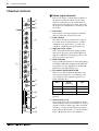
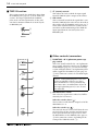
WARNING: THIS APPARATUS MUST BE EARTHED
IMPORTANT
THE WIRES IN THIS MAINS LEAD ARE COLOURED IN
ACCORDANCE WITH THE FOLLOWING CODE:
GREEN-AND-YELLOW :
EARTH
BLUE :
NEUTRAL
BROWN :
LIVE
As the colours of the wires in the mains lead of this apparatus may
not correspond with the coloured markings identifying the terminals in
your plug, proceed as follows:
The wire which is coloured GREEN and YELLOW must be
connected to the terminal in the plug which is marked by the letter E
or by the safety earth symbol
or coloured GREEN and YELLOW.
The wire which is coloured BLUE must be connected to the terminal
which is marked with the letter N or coloured BLACK.
The wire which is coloured BROWN must be connected to the
terminal which is marked with the letter L or coloured RED.
* This applies only to products distributed by YAMAHA KEMBLE
MUSIC (U.K.) LTD.
Precautions
3
Precautions
Warnings
Cautions
• Do not allow water to enter this unit or allow the
unit to become wet. Fire or electrical shock may
result.
• Connect this unit’s power cord only to an AC outlet of the type stated in this Owner’s Manual or as
marked on the unit. Failure to do so is a fire and
electrical shock hazard.
• Do not scratch, bend, twist, pull, or heat the power
cord. A damaged power cord is a fire and electrical
shock hazard.
• Do not place heavy objects, including this unit, on
top of the power cord. A damaged power cord is a
fire and electrical shock hazard. In particular, be
careful not to place heavy objects on a power cord
covered by a carpet.
• If you notice any abnormality, such as smoke,
odor, or noise, or if a foreign object or liquid gets
inside the unit, turn it off immediately. Remove
the power cord from the AC outlet. Consult your
dealer for repair. Using the unit in this condition is
a fire and electrical shock hazard.
• Should this unit be dropped or the cabinet be
damaged, turn the power switch off, remove the
power plug from the AC outlet, and contact your
dealer. If you continue using the unit without
heeding this instruction, fire or electrical shock
may result.
• If the power cord is damaged (i.e., cut or a bare
wire is exposed), ask your dealer for a replacement.
Using the unit with a damaged power cord is a fire
and electrical shock hazard.
• Do not remove the unit’s cover. You could receive
an electrical shock. If you think internal inspection, maintenance, or repair is necessary, contact
your dealer.
• Do not modify the unit. Doing so is a fire and electrical shock hazard.
• This unit has ventilation holes at the top and right
side to prevent the internal temperature rising too
high. Do not block them. Blocked ventilation holes
are a fire hazard.
• Hold the power cord plug when disconnecting it
from an AC outlet. Never pull the cord. A damaged
power cord is a potential fire and electrical shock
hazard.
• Do not touch the power plug with wet hands.
Doing so is a potential electrical shock hazard.
Operating Notes
• Using a mobile telephone near this unit may
induce noise. If noise occurs, use the telephone
away from the unit.
• XLR-type connectors are wired as follows:
pin 1: ground, pin 2: hot (+), and pin 3: cold (–).
• Insert TRS phone jacks are wired as follows:
sleeve: ground, tip: send, and ring: return.
• The performance of components with moving
contacts, such switches, rotary controls, faders,
and connectors, deteriorates over time. The rate of
deterioration depends on the operating environment and is unavoidable. Consult your dealer
about replacing defective components.
—Owner’s Manual
4
Introduction
Introduction
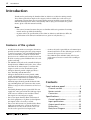
Thank you for purchasing the Yamaha GF24/12, GF16/12, or GF12/12 mixing console.
These mixers provide an ample twelve outputs, and are suitable for a wide variety of
applications ranging from concert sound reinforcement to installed systems. In order to
take full advantage of the mixer’s functionality and to enjoy years of trouble-free performance, please read this manual carefully.
Note:
• This owner’s manual assumes that you are familiar with basic operation of a mixing
console and its specialized vocabulary.
• At points where the specifications of the GF24/12, GF16/12, and GF12/12 differ, the
specifications of the GF16/12 and GF12/12 are given in curly brackets { }.
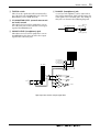
Features of the system
• In addition to the main stereo outputs, this mixer
provides six AUX outputs plus four group outputs
(a total of 12 outputs). The AUX/GROUP outputs
can be used not only as sends to external effect
processors or to a multitrack recorder, but are also
ideal for creating separate foldback mixes for each
speaker and amp.
• The MONO OUT jack can be controlled independently from the STEREO OUT jacks. Since a monaural mix of the main output is sent from this
output, it can be used to extend a PA system.
• All input channels provide a high-pass filter, a
three-band EQ, and 60 mm faders.
• All input channels/AUX returns provide a PFL
switch, and AUX/group/stereo output channels
provide an AFL switch. You can audition input and
output sources at the touch of a button.
• All mono input channels provide balanced XLR
type and TRS phone jack connectors that accommodate a range of sources from mics to line level
devices.
• Switchable phantom power is provided. This can
supply DC +48 V power from the XLR type input
connectors to condenser mics and direct boxes
that require an external power supply.
• Two stereo input channels allow connection of
line-level equipment. 1/4" phone jack and phono
jack inputs can be selected by a switch.
• Two stereo AUX returns are provided. This allows
AUX return signals to be sent to an AUX bus or
GROUP bus as well as to the ST bus. These can
also be used as spare line level input jacks.
—Owner’s Manual
• An insert I/O jack is provided on each mono input
channel and on the ST bus, allowing you to insert
external effect processors as desired.
• The TAPE IN jacks and REC OUT jacks let you
easily connect a master recorder for recording or
playback.
Contents
Front and rear panel ....................... 5
Channel controls ..................................6
Master controls ..................................10
Connectors ........................................17
Specifications................................ 21
General specifications.........................21
Input specifications ............................22
Output specifications .........................22
Dimensions ........................................23
Block/Level Diagram ..........................24
Front and rear panel
5
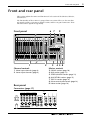
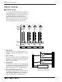
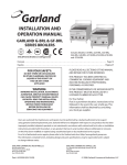
Front and rear panel
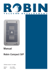
This section explains the names and functions of each section of the GF24/12, GF16/12,
and GF12/12.
The functionality of these mixers is grouped into ten sections. These are the two channel control sections, seven master control sections, and the rear panel connectors. Their
functions will be explained sequentially.
Front panel
6 7
9
POWER
1
2
3
26dB
GAIN
26dB
GAIN
–34
–60
+10
–15
7
26dB
GAIN
–34
–60
+10
–15
80
HIGH
HIGH
HIGH
GAIN
–34
–60
+10
–15
HIGH
HIGH
GAIN
–34
–60
+10
–15
HIGH
HIGH
HIGH
GAIN
–34
–60
+10
–15
80
PEAK
HIGH
–34
1
–34
GROUP
0
10
0
10
3
0
10
0
10
30
10
80
PEAK
HIGH
HIGH
GROUP
+10
80
PEAK
PEAK
HIGH
A
B
GAIN
+10
80
PEAK
2
HIGH
4
AUX
PEAK
+8
+5
+3
+1
0
–1
–3
–5
–7
–10
–15
–20
PEAK
+8
+5
+3
+1
0
–1
–3
–5
–7
–10
–15
–20
23/24
A
B
26dB
GAIN
–34
–60
+10
–15
80
PEAK
HIGH
26dB
GAIN
–34
–60
+10
–15
80
PEAK
21/22
20
26dB
GAIN
–34
–60
+10
–15
80
PEAK
19
26dB
GAIN
80
PEAK
18
26dB
–34
–60
+10
–15
80
PEAK
17
26dB
GAIN
–34
–60
+10
–15
80
PEAK
11
26dB
GAIN
80
PEAK
10
26dB
–34
–60
+10
–15
80
PEAK
9
26dB
GAIN
–34
–60
+10
–15
80
PEAK
8
26dB
GAIN
–34
–60
+10
–15
80
PEAK
HIGH
6
26dB
GAIN
–34
–60
+10
–15
80
PEAK
HIGH
5
26dB
GAIN
–34
–60
+10
–15
80
PEAK
HIGH
4
AUX
L
R
L
STEREO
–15
+15
MID
–15
+15
MID
250
5K
–15
+15
MID
250
5K
–15
+15
–15
MID
250
5K
+15
MID
250
5K
–15
+15
–15
MID
250
5K
+15
MID
250
5K
–15
+15
–15
MID
250
5K
+15
MID
250
5K
–15
+15
–15
MID
250
5K
+15
–15
MID
250
5K
+15
MID
250
5K
–15
+15
MID
250
5K
–15
+15
MID
250
5K
–15
+15
–15
+15
–15
+15
–15
+15
LOW
–15
+15
–15
+15
LOW
–15
AUX
+15
–15
+15
–15
LOW
–15
AUX
+15
+15
LOW
–15
+15
AUX
–15
+15
–15
LOW
–15
AUX
+15
+15
LOW
–15
AUX
+15
–15
+15
–15
LOW
–15
AUX
+15
+15
LOW
–15
AUX
+15
–15
+15
–15
LOW
–15
+15
AUX
+15
–15
LOW
–15
+15
AUX
+15
LOW
–15
+15
AUX
–15
250
+15
LOW
–15
+15
AUX
5K
–15
250
+15
LOW
–15
+15
AUX
10
+15
2
5K
MID
LOW
–15
10
10
40
10
1
–15
+15
–15
+15
LOW
–15
AUX
MID
+15
LOW
–15
+15
AUX
0
ST
–15
ST
+15
0
0
10
10
0
PRE
0
10
0
10
1
PRE
0
10
0
10
1
PRE
0
10
0
10
1
PRE
0
10
0
10
1
PRE
0
10
0
10
1
PRE
0
10
0
10
1
PRE
0
10
0
10
1
PRE
0
10
0
10
1
PRE
0
10
0
10
1
PRE
0
10
0
10
1
PRE
0
10
0
10
PRE
1
0
10
0
10
1
PRE
0
10
0
10
1
PRE
0
10
0
10
1
+15
–15
AUX
PRE
0
10
0
10
1
10
LOW
–15
AUX
+15
PFL
AUX
ON
PFL
1 AUX RETURN 2
1
R
PFL•AFL/TAPE IN PHANTOM
3
4
2
MID
PRE
0
10
0
10
1
TAPE IN
MIXING CONSOLE
PRE
0
10
0
10
PHANTOM +48V
2
3
PRE
0
10
0
10
5
0
10
6
0
10
4
2
3
PRE
PRE
0
10
0
10
5
0
10
6
0
10
4
2
3
PRE
PRE
0
10
0
10
5
0
10
6
0
10
4
2
3
PRE
PRE
0
10
0
10
5
0
10
6
0
10
4
2
3
PRE
PRE
0
10
0
10
5
0
10
6
0
10
4
2
3
PRE
PRE
0
10
0
10
5
0
10
6
0
10
4
2
3
PRE
PRE
0
10
0
10
5
0
10
6
0
10
4
2
3
PRE
PRE
0
10
0
10
5
0
10
6
0
10
4
2
3
PRE
PRE
0
10
0
10
5
0
10
6
0
10
4
2
3
PRE
PRE
0
10
0
10
5
0
10
6
0
10
4
2
3
PRE
PRE
0
10
0
10
5
0
10
6
0
10
4
2
PRE
3
0
10
0
10
5
0
10
6
0
10
4
PRE
2
3
PRE
PRE
0
10
0
10
5
0
10
6
0
10
4
2
3
PRE
PRE
0
10
0
10
5
0
10
6
0
10
4
2
3
PRE
PRE
0
10
0
10
5
0
10
6
0
10
4
2
3
PRE
PRE
0
10
0
10
5
0
10
6
0
10
4
2
3
10
0
10
5
0
10
6
0
10
4
PRE
10
10
10
10
10
5
5
5
5
5
5
0
0
0
0
0
0
5
5
5
5
5
5
10
10
10
10
10
10
OFF
PRE
0
10
15
20
30
40
PRE
15
20
30
40
15
20
30
40
AFL
PAN
PAN
L
ODD
R
EVEN
PAN
L
ODD
R
EVEN
PAN
L
ODD
R
EVEN
PAN
L
ODD
R
EVEN
PAN
L
ODD
R
EVEN
PAN
L
ODD
R
EVEN
PAN
L
ODD
R
EVEN
PAN
L
ODD
R
EVEN
PAN
L
ODD
R
EVEN
PAN
L
ODD
R
EVEN
PAN
L
ODD
R
EVEN
PAN
L
ODD
R
EVEN
PAN
L
ODD
R
EVEN
PAN
L
ODD
R
EVEN
BAL
L
ODD
R
EVEN
L
ODD
R
EVEN
R
EVEN
R
AUX 4
PAN
L
R
AUX 5
R
STEREO PFL•AFL
GROUP
AFL
TAPE IN
AUX 6
MONO
PAN
L
15
20
30
40
AFL
AFL
AUX 3
PAN
L
AFL
AUX 2
PAN
L
ODD
15
20
30
40
15
20
30
40
AFL
AUX 1
BAL
ON
METER SELECT
L
R
0
0
10
10
C-R MONITOR
LEVEL
ON
ON
10
ON
10
1–2
ON
10
1–2
ON
10
1–2
ON
10
1–2
ON
10
1–2
ON
10
1–2
ON
10
1–2
ON
10
1–2
ON
10
1–2
ON
10
1–2
ON
10
1–2
ON
10
1–2
ON
10
1–2
ON
10
1–2
TO ST
ON
10
1–2
10
1–2
TO ST
TO ST
POST
TO ST
10
10
10
10
10
5
5
5
5
5
0
3–4
0
3–4
0
3–4
0
3–4
0
3–4
0
3–4
0
3–4
0
3–4
0
3–4
0
3–4
0
3–4
0
3–4
0
3–4
0
3–4
0
3–4
0
3–4
0
3–4
0
0
0
0
0
5
ST
5
ST
5
ST
5
ST
5
ST
5
ST
5
ST
5
ST
5
ST
5
ST
5
ST
5
ST
5
ST
5
ST
5
ST
5
ST
5
ST
5
5
5
5
5
5
5
10
5
10
15
20
30
40
10
15
20
30
40
PFL
1
5
2
10
15
20
30
40
PFL
5
10
15
20
30
40
PFL
3
5
10
15
20
30
40
PFL
6
5
10
15
20
30
40
PFL
5
5
10
15
20
30
40
PFL
4
5
10
15
20
30
40
PFL
9
5
10
15
20
30
40
PFL
8
5
10
15
20
30
40
PFL
7
5
10
15
20
30
40
PFL
10
5
10
15
20
30
40
PFL
17
5
10
15
20
30
40
PFL
18
5
10
15
20
30
40
PFL
11
5
19
5
10
15
20
30
40
PFL
1
10
15
20
30
40
15
20
30
40
PFL
21/22
20
10
10
15
20
30
40
PFL
0
PFL
23/24
GROUP 1
10
15
20
30
40
AFL
10
15
20
30
40
AFL
GROUP 2
GROUP 3
15
20
30
40
AFL
GROUP 4
3
2
10
15
20
30
40
AFL
10
PHONES
LEVEL
1–2
PHONES
AFL
STEREO
4 5 8
Channel controls
Master controls
1. Mono input channels (page 6)
2. Stereo input channels (page 8)
3. GROUP section (page 10)
4. AUX section (page 11)
5. STEREO/MONO section (page 12)
6. AUX RETURN section (page 13)
7. TAPE IN section (page 14)
8. Other controls/connectors (page 14)
9. Meter section (page 16)
Rear panel
Connectors (page 17)
INSERT I/O
C-R
OUT +4dB
R
POWER
ON/ OFF
ST INSERT I/O 0dB
L R
4
3
6
5
GROUP OUT +4dB
2
AUX RETURN +4dB
L 2L
2R
1
1R 23L
AUX OUT +4dB (BALANCE)
4
3
OUT IN
1L
(MONO)
2
INPUT B
21L
24R
1
INSERT I/O
0dB
INSERT I/O
0dB
INSERT I/O
0dB
INPUT
INPUT
INPUT
B
B
B
22R
TAPE IN –10dBV
23L
R
MONO OUT +4dBV
L
STEREO OUT +4dBV
R
L
REC OUT –10dBV
(MONO)
24R
21L
22R
INPUT A
INPUT A
INPUT A
INPUT A
—Owner’s Manual
6
Front and rear panel
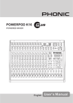
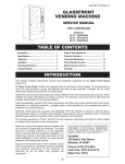
Channel controls
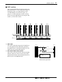
■ Mono input channels
26dB
GAIN
–34
–60
+10
–16
2
3
80
4
1
PEAK
Here are the 20 {12, 8} mono input channels of
the GF24/12 {GF16/12, GF12/12}. The input
channel section processes the signal from the
input jacks of the connector section, and sends
the result to the GROUP buses, AUX buses, and
the ST bus.
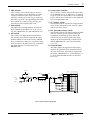
1 Pad switch
HIGH
–15
This attenuates the input signal by 26 dB. The
pad is on when this switch is pressed in.
+15
MID
2 GAIN control
250
5K
–15
+15
5
LOW
–15
3 High pass filter switch
+15
AUX
1
10
0
10
0
10
0
10
5
0
10
6
0
10
2
6
3
4
This is an on/off switch for the high pass filter
that cuts the frequency range below 80 Hz at a
slope of 12 dB/octave. The high pass filter is on
when the switch is pressed in.
PRE
0
This adjusts the input sensitivity. The range of
levels that can be accommodated is –16 dB to
–60 dB when the pad switch (1) is off, and
+10 dB to –34 dB when the pad switch is on.
4 PEAK indicator
PRE
7
PRE
This is an indicator that detects post-EQ clipping.
It will light 3 dB before clipping, indicating that
the signal is near the clipping level. If this LED
lights, lower the GAIN control (2).
5 EQ controls (HIGH/MID/LOW)
This is a three-band equalizer that boosts/cuts
each frequency band over a ± 15 dB range. The
center frequency and equalizer type for each
band is shown below.
PAN
8
L
ODD
R
EVEN
Band
Center
frequency
Type
HIGH
10 kHz
shelving
MID
250 Hz–5 kHz
peaking
LOW
100 Hz
shelving
9
ON
10
1–2
0
5
0
3–4
A
5
ST
6 AUX controls (1–6)
10
15
20
30
40
The response is flat when the knob is in the “▼”
position.
B
PFL
C
—Owner’s Manual
These knobs adjust the level at which the input
channel signal is sent to the AUX buses 1–6. AUX
controls 1 and 2 are fixed at pre-fader, and AUX
controls 3–6 can be switched between pre/post
fader using the PRE switch (7). When a knob is
in the “√” position, the level is “nominal”.
Channel controls
7 PRE switches
7
0 Group select switches
These switches select whether the pre or post fader signal will be sent to AUX buses 3–6. This
setting is switched in pairs: AUX 3/4 and 5/6.
When the switch is pressed in, the pre-fader signal will be sent to the corresponding pair of AUX
buses. When the switch is in the out (up) position, the post-fader signal will be sent.
These switches send the signal of the input channel to GROUP buses 1–4. When the 1–2 switch is
on (pressed in) the signal will be sent to GROUP
bus 1/2. When the 3–4 switch is on, the signal will
be sent to GROUP bus 3/4.
A ST (stereo) switch
This switch sends the signal of the input channel
to the ST bus. When this switch is on, the signal
will be sent to the ST bus.
8 PAN control
This adjusts the left/right position at which the
input channel signal will be sent to the ST (stereo) bus, GROUP bus 1/2, and GROUP bus 3/4.
B PFL (pre-fader listen) switch
This switch sends the pre-fader signal to the PFL/
AFL bus, allowing you to monitor it through
headphones or monitor speakers. When this
switch is on, the pre-fader signal of the input
channel can be heard from the C-R OUT jacks
and the PHONES jack, even if the ON switch
(9) is off.
9 ON switch
This switches the input channel on/off. When
this switch is turned off, the signal of the input
channel will not be sent to the ST bus, GROUP
buses, or AUX buses. However even if this switch
is off, you can use the PFL switch (B) to monitor
the signal from the C-R OUT jacks or the
PHONES jack.
C Channel fader
This fader adjusts the input level of the input
channel. The position of the channel fader will
affect the level of the signal that is output from
the ST bus, GROUP buses 1–4, and AUX buses 1–
6 (except when the PRE switch is on for AUX
buses 3–6).
PHANTOM
GROUP
AUX PFL/AFL ST
1 2 3 4 1 2 3 4 5 6 L R L R
+48V
PAD
ST
HA
1-20
{1-12}
{1-8}
HPF
1-2
PAN
80
GAIN
g
g
3-4
HIGH
26dB
f
g
ON
MID
INPUT B
3 Stage EQ
LOW
INPUT A
PEAK
INSERT I/O
0dB
PHANTOM
+48V
AUX 1
AUX 2
AUX 3
PRE
AUX 4
AUX 5
PRE
AUX 6
PFL
Mono input channel signal flow
—Owner’s Manual
8
Front and rear panel
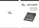
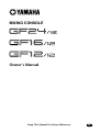
■ Stereo input channels
A
B
GAIN
1
2
+10
–34
3
80
4
PEAK
HIGH
–15
+15
5
MID
–15
+15
AUX
1
2
3
PRE
0
10
0
10
10
0
10
5
0
10
6
0
10
4
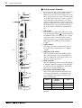
2 GAIN control
This adjusts the input sensitivity. The range of
levels that can be accommodated is +10 dB to
–34 dB.
PRE
0
6
1 A/B switch
This switch selects input jacks. When the switch
is in the upward position ( ) the input signal of
the INPUT A jack is selected (page 18, 6 of the
connector section). When the switch is in the
downward section ( ), the input signal of the
INPUT B jack is selected (0 of the connector
section).
+15
LOW
–15
Here are the two stereo input channels provided
by the GF24/12, GF16/12, and GF12/12. The
INPUT 21/22 and 23/24 {13/14 and 15/16 on the
GF16, and 9/10 and 11/12 on the GF12/12} jacks
(6 and 0 of the connector section) are pairs of
connectors that let you control a stereo signal
using one input channel. If a cable is connected
only to the INPUT A 21L or 23L jack {13L or 15L
on the GF16/12, or 9L or 11L on the GF12/12},
the source will be controlled as a monaural signal.
3 High pass filter switch
7
PRE
4 PEAK indicator
BAL
8
L
ODD
This is an on/off switch for the high pass filter
that cuts the frequency range below 80 Hz at a
slope of 12 dB/octave. The high pass filter is on
when the switch is pressed in.
R
EVEN
9
ON
This is an indicator that detects post-EQ clipping.
It will light 3 dB before clipping, indicating that
the signal is near the clipping level. If this LED
lights, lower the GAIN control (2).
5 EQ controls (HIGH/MID/LOW)
10
1–2
0
5
0
3–4
5
ST
A
10
15
20
30
40
B
PFL
C
—Owner’s Manual
This is a three-band equalizer that boosts/cuts
each frequency band over a ±15 dB range. The
center frequency and equalizer type for each
band is shown below.
Band
Center
frequency
Type
HIGH
10 kHz
shelving
MID
250 Hz
peaking
LOW
100 Hz
shelving
The response is flat when the knob is in the “▼”
position.
Channel controls
6 AUX controls (1–6)
9
0 Group select switches
These knobs adjust the level at which the input
channel signal is sent to the AUX buses 1–6. AUX
controls 1 and 2 are fixed at pre-fader, and AUX
controls 3–6 can be switched between pre/post
fader using the PRE switch (7). When a knob is
in the “√” position, the level is “nominal.”
These switches send the signal of the input channel to GROUP buses 1–4. When the 1–2 switch is
on (pressed in) the signal will be sent to GROUP
bus 1/2. When the 3–4 switch is on, the signal will
be sent to GROUP bus 3/4.
A ST (stereo) switch
7 PRE switches
This switch sends the signal of the input channel
to the ST bus. When this switch is on, the signal
will be sent to the ST bus.
These switches select whether the pre or post fader signal will be sent to AUX buses 3–6. This
setting is switched in pairs: AUX 3/4 and 5/6.
When the switch is pressed in, the pre-fader signal will be sent to the corresponding pair of AUX
buses. When the switch is in the upward position,
the post-fader signal will be sent.
B PFL (pre-fader listen) switch
This switch sends the pre-fader signal to the PFL/
AFL bus, allowing you to monitor it through
headphones or monitor speakers. When this
switch is on, the pre-fader signal of the input
channel can be heard from the C-R OUT jacks
and the PHONES jack, even if the ON switch
(9) is off.
8 BAL (balance) control
This adjusts the left/right balance at which the
signal of the stereo input channel will be sent to
the ST (stereo) bus, GROUP bus 1/2, and
GROUP bus 3/4.
C Channel fader
This fader adjusts the input level of the stereo
input channel. The position of the channel fader
will affect the level of the signal that is output
from the ST bus, GROUP buses 1–4, and AUX
buses 1–6 (except when the PRE switch is on for
AUX buses 3–6).
9 ON switch
This switches the input channel on/off. When
this switch is turned off, the signal of the input
channel will not be sent to the ST bus, GROUP
buses, or AUX buses. However even if this switch
is off, you can use the PFL switch (B) to monitor
the signal from the C-R OUT jacks or the
PHONES jack.
GROUP
AUX PFL/AFL ST
1 2 3 4 1 2 3 4 5 6 L R L R
PEAK
ST
A
GAIN
*2,*4
HA
80
HIGH
HPF
B
INPUT A
3 Stage EQ
MID
HA
LOW
*1,*3
(MONO)
ON
BAL
1-2
3 Stage EQ
HPF
80
3-4
*1,*3
INPUT B
AUX 1
*2,*4
AUX 2
AUX 3
PRE
AUX 4
AUX 5
No. GF12/12 GF16/12
*1
9L
13L
GF24/12
PRE
AUX 6
21L
PFL
*2
10R
14R
*3
11L
15L
23L
*4
12R
16R
24R
22R
Stereo input channel signal flow
—Owner’s Manual
10
Front and rear panel
Master controls
■ GROUP section
This section individually controls the output signal of GROUP buses 1–4. The signal that passes
through the GROUP 1–4 output channels can be
sent individually from the GROUP OUT 1–4
output jacks (page 20, D in the connector section), and can also be sent to the ST bus or PFL/
AFL bus by using the TO ST switch (group section 2) and AFL switch (group section 4).
PAN
PAN
PAN
PAN
1
L
2
R
L
TO ST
3
R
L
TO ST
R
L
TO ST
R
TO ST
10
10
10
10
5
5
5
5
0
0
0
0
5
5
5
5
10
10
10
10
15
20
30
40
15
20
30
40
15
20
30
40
15
20
30
40
AFL
AFL
AFL
AFL
4
GROUP 1
GROUP 2
GROUP 3
GROUP 4
1 PAN control
This knob adjusts the left/right position when
sending the signal of each GROUP bus 1–4 to the
ST bus.
ST PFL/AFL
L R L R
to Meter
GROUP
1 2 3 4
PAN
TO ST
2 TO ST switch
GROUP OUT 1
This switch sends the signal of each GROUP bus
1–4 to the ST bus. When the switch is on, the signal that has passed through the PAN control (1)
will be sent to the ST bus.
AFL
to Meter
PAN
TO ST
GROUP OUT 2
3 Group fader
This adjusts the output level of each GROUP bus
1–4. The position of the group fader will affect all
signals that are sent from the GROUP bus to the
GROUP OUT jacks, ST bus, and PFL/AFL bus.
4 AFL (after-fader listen) switch
This switch sends the signal of the GROUP bus to
the PFL/AFL bus. If this switch is on, the afterfader signal of the GROUP bus can be monitored
in the C-R OUT jacks or the PHONES jack.
—Owner’s Manual
AFL
GROUP OUT 3-4:
Same as GROUP OUT 1-2
Group section signal flow
Master controls
11
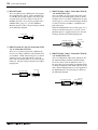
■ AUX section
This section individually controls the output signals of AUX buses 1–6. The signal that has passed
through the AUX 1–6 output channels can be
sent individually to the AUX OUT jacks 1–6
(page 17, 1 in the connector section), and can
also be sent to the PFL/AFL bus by using the AFL
switch (2 in the AUX section).
1
10
10
10
10
10
10
5
5
5
5
5
5
0
0
0
0
0
0
5
5
5
5
5
5
10
10
10
10
10
10
15
20
30
40
15
20
30
40
15
20
30
40
15
20
30
40
15
20
30
40
15
20
30
40
AFL
2
AUX 1
AFL
AUX 2
AFL
AUX 3
AFL
AFL
AUX 4
AUX 5
AFL
AUX 6
1 AUX fader
These faders adjust the output level of AUX buses
1–6. The position of the AUX faders will affect
the signals that are sent from the AUX bus to the
AUX OUT jacks and the PFL/AFL bus.
AUX
1 2 3 4 5 6
PFL/AFL
L R
AUX OUT 1
AFL
AUX OUT 2
2 AFL (after-fader listen) switch
This switch sends the AUX bus signal to the PFL/
AFL bus. When the switch is on, the after-fader
signal of the AUX bus can be monitored in the CR OUT jacks or the PHONES jack.
AFL
AUX OUT 3-4:
AUX OUT 5-6:
Same as AUX OUT 1-2
AUX section signal flow
—Owner’s Manual
12
Front and rear panel
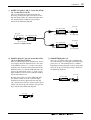
■ STEREO/MONO section
1 MONO (monaural) control
This section separately controls the STEREO
OUT jacks (page 17, 3 in the connector section)
which are the main output of the mixer, and the
MONO OUT jack (page 17, 2 in the connector
section) which outputs a monaural mix of the
STEREO OUT output.
MONO
1
0
2
10
POST
2 POST switch
This switches the output of the fader between the
pre- and post-fader signals. When this switch is
pressed in, the signal after passing through the
STEREO fader (post-fader) will be sent to the
MONO OUT jack. When this switch is in the
upward position, the signal before passing
through the STEREO fader (pre-fader) will be
sent to the MONO OUT jack.
3 STEREO fader
10
This adjusts the level of the signal that is sent to
the STEREO OUT jack. The position of the STEREO fader will affect the signals that are sent
from the ST bus to the STEREO OUT jacks, the
MONO OUT jack (if the POST switch 2 is on),
and the PFL/AFL bus.
5
0
5
10
15
20
30
40
3
This adjusts the signal level that is sent to the
MONO OUT jack. The level is nominal when the
control is at the “√” position.
4 AFL (after-fader listen) switch
4
AFL
STEREO
This switch sends the signal of the ST bus to the
PFL/AFL bus. When the switch is on, the signal
following the STEREO fader (the same signal as
output from the STEREO OUT jacks) can be
monitored from the C-R OUT jacks and the
PHONES jack.
ST
L R
PFL/AFL
L R
to Meter
ST
INSERT
I/O L
to Meter
L
ST
INSERT
I/O R
STEREO
OUT
R
L
PAD
REC OUT
R
AFL
MONO
OUT
POST MONO
STEREO/MONO section signal flow
—Owner’s Manual
Master controls
■ AUX RETURN section
1 GROUP 1/2, AUX 1/2 mix controls
These controls adjust the level at which signals
from the AUX RETURN 1 jacks are sent to
GROUP bus 1/2 and AUX bus 1/2. When a stereo
signal is input, the signals of the L and R channels
will be sent to GROUP buses 1/2 and AUX buses
1/2 respectively. When a monaural signal is input,
the same signal will be sent to GROUP buses 1
and 2, and to AUX buses 1 and 2.
This section controls the two stereo AUX returns.
By using the L and R jacks of AUX RETURN 1/2
(page 19, A in the connector section) in pairs,
you can input stereo signals. If only the L jack of
AUX RETURN 1/2 is connected, this can be used
as a monaural AUX return. The input signal from
AUX RETURN jack 1 can also be sent to GROUP
bus 1/2 and AUX bus 1/2, and the input signal
from AUX RETURN jack 2 can be sent to
GROUP bus 3/4 and AUX bus 3/4.
GROUP
1
2 GROUP 3/4, AUX 3/4 mix controls
These controls adjust the level at which signals
from the AUX RETURN 2 jacks are sent to
GROUP bus 3/4 and AUX bus 3/4. When a stereo
signal is input, the signals of the L and R channels
will be sent to GROUP buses 3/4 and AUX buses
3/4 respectively. When a monaural signal is input,
the same signal will be sent to GROUP buses 3
and 4, and to AUX buses 3 and 4.
GROUP
0
3
10
0
13
10
3 ST (stereo) controls
1
2
0
10
AUX
3
4
0
10
10
10
30
10
20
10
ST
40
10
0
10
These adjust the level at which the input signals
from the AUX RETURN 1/2 jacks are sent to the
ST bus. The position of the stereo control knobs
does not affect the GROUP 1–4 and AUX 1–4
mix controls (1 and 2).
2
AUX
4 PFL (pre-fader listen) switch
ST
0
10
These switches send the input signal from the
AUX RETURN 1/2 jacks to the PFL/AFL bus.
When this switch is on, the input signal from the
AUX RETURN 1/2 jacks can be monitored
directly from the C-R OUT jacks or the PHONES
jack.
4
PFL
PFL
1 AUX RETURN 2
GROUP
AUX
ST PFL/AFL
1 2 3 4 1 2 3 4 5 6 L R L R
L
(MONO)
AUX RETURN 1
R
GROUP 1
GROUP 2
AUX 1
AUX 2
ST
PFL
L
(MONO)
AUX RETURN 2
R
GROUP 3
GROUP 4
AUX 3
AUX 4
ST
PFL
AUX RETURN section signal flow
—Owner’s Manual
14
Front and rear panel
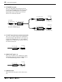
■ TAPE IN section
1 ST (stereo) control
This section controls the signal that is input from
the TAPE IN jacks (page 17, 4 in the connector
section). The input signal from the TAPE IN
jacks can be sent directly from the ST bus, and
can also be monitored from the C-R OUT jacks
or PHONES jack.
1
0
10
2
This adjusts the level at which the input signal
from the TAPE IN jacks is output to the ST bus.
2 ON switch
This is an on/off switch for the signal that is sent
from the TAPE IN jacks to the ST bus. Even when
this switch is off, the TAPE IN switch (page 15, 3
in the other controls/connector section) can be
turned on to allow monitoring of the TAPE IN
input signal from the C-R OUT jacks or the
PHONES jack.
ON
TAPE IN
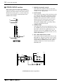
■ Other controls/connectors
1 PHANTOM +48 V (phantom power sup-
PHANTOM +48V
1
OFF
ON
METER SELECT
2
STEREO PFL•AFL
GROUP
3
TAPE IN
4
0
10
C-R MONITOR
LEVEL
5
0
10
PHONES
LEVEL
ply) switch
This is the on/off switch for the +48 V phantom
power supply. When this switch is on, the PHANTOM indicator (page 16, 3 in the meter bridge
section) will light, and DC +48 V phantom power
will be supplied to the INPUT A jacks (page 18,
7 in the connector section) of each mono input
channel.
Caution: When phantom power is on, connecting an unbalanced device or a device
whose transformer is center-grounded may
cause hum, noise, or malfunctions. If you do
not require phantom power, be sure to turn
this switch off.
2 METER SELECT switch
This selects the signal source whose level will be
shown by the level meters.
When the switch is down ( )
The level meters will show the output level of the
GROUP buses 1–4.
PHONES
6
—Owner’s Manual
When the switch is up ( )
The two level meters at the left will show the output level of the ST bus, and the two level meters
at the right will show the output level of either
the PFL/AFL bus or the TAPE IN jacks (page 17,
4 in the connector section), depending on the
setting of the TAPE IN switch (3).
Master controls
3 TAPE IN switch
15
6 PHONES (headphone) jack
This selects the signal that will be monitored by
the C-R OUT jacks and PHONES jack: either the
PFL/AFL bus, or the TAPE IN jacks.
4 C-R MONITOR LEVEL (control room moni-
A set of stereo headphones can be connected to
this jack for monitoring. This jack will output the
same signal as the C-R OUT jacks. The wiring of
this jack is as shown in the following diagram.
tor level) control
This adjusts the level of the signal that is sent to
the C-R OUT jacks. It does not affect the output
signal of the PHONES jack.
Tip (hot)
1/4" TRS phone plug
5 PHONES LEVEL (headphone) jack
Ring (cold)
Sleeve (ground)
This adjusts the level of the signal that is sent to
the PHONES jack. It does not affect the output
signal of the C-R OUT jacks.
from STEREO OUT L
from GROUP OUT 1
from STEREO OUT R
from GROUP OUT 2
ST PFL/AFL
L R L R
from GROUP OUT 3
from GROUP OUT 4
METER SELECT
BA
TAPE IN
L
C-R MONITOR
LEVEL
C-R OUT
BA
R
L
TAPE IN
ST
ON
BA
R
PHONES
LEVEL
PHONES
BA
Tape input and monitor output signal flow
—Owner’s Manual
16
Front and rear panel
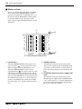
■ Meter section
This is a peak level meter that shows (according
to the setting of the METER SELECT switch,
page 14) the output levels of GROUP buses 1–4,
the ST bus, and the PFL/AFL bus, and the input
level of the TAPE IN jacks. The status of the
mixer’s power supply and phantom power is also
shown here.
1
2
POWER
PEAK
+8
+5
+3
+1
0
–1
–3
–5
–7
–10
–15
–20
PEAK
+8
+5
+3
+1
0
–1
–3
–5
–7
–10
–15
–20
L
R
STEREO
1
2
1 Level meters
L
R
3
PFL•AFL/TAPE IN PHANTOM
3
4
2 POWER indicator
When the METER SELECT switch (page 14) is
pressed inward ( ), the four level meters will
show the output levels of GROUP buses 1–4.
When the METER SELECT switch is in the
upward position ( ), the two level meters at left
will show the output level of the ST bus, and the
two level meters at right will show either the output level of the PFL/AFL bus or the input level of
the TAPE IN jacks (page 17, 4 of the connector
section), depending on the setting of the TAPE
IN switch (page 15, 3 of other controls/connectors).
—Owner’s Manual
This indicator shows the on/off status of the
mixer’s power supply. When the POWER switch
(page 20, E in the connector section) has been
pressed to turn on the power, this indicator will
light.
3 PHANTOM (phantom power supply) indicator
This indicator shows the on/off status of the
phantom power supply. When the PHANTOM
+48 V switch (page 14, 1 in other controls/connectors) has been slid to turn on the phantom
power, this indicator will light.
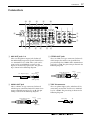
Connectors
17
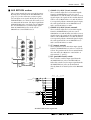
Connectors
D
C
B
A
0
INSERT I/O
C-R
OUT +4dB
R
POWER
ON/ OFF
E
ST INSERT I/O 0dB
L R
4
3
6
5
AUX RETURN +4dB
L 2L
GROUP OUT +4dB
2
2R
1
1R 23L
AUX OUT +4dB (BALANCE)
4
3
OUT IN
1L
(MONO)
2
INPUT B
21L
24R
1
INSERT I/O
0dB
INSERT I/O
0dB
INSERT I/O
0dB
INPUT
INPUT
INPUT
B
B
B
9
22R
8
TAPE IN –10dBV
23L
R
MONO OUT +4dBV
1 2
L
R
4
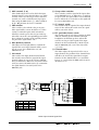
1 AUX OUT jacks 1–6
7
INPUT A
INPUT A
INPUT A
INPUT A
6
3 STEREO OUT jacks
These are TRS phone output jacks (balanced)
that individually output the signals of AUX buses
1–6. Nominal level is +4 dB. These jacks can be
connected to your foldback system or to the
inputs of external effect processors. The pin wiring is shown in the following diagram.
Tip (hot)
1/4" TRS phone plug
5
21L
22R
24R
REC OUT –10dBV
STEREO OUT +4dBV
3
L
(MONO)
These are XLR-3-32 type connectors (balanced)
which output the main stereo signal that has
passed through the STEREO fader. Nominal output level is +4 dB. The pin wiring is shown in the
following diagram.
Female XLR connector
2 (hot)
3 (cold)
Ring (cold)
1 (ground)
Sleeve (ground)
2 MONO OUT jack
4 TAPE IN connector
This is a XLR-3-32 type connector (balanced)
which outputs a monaural mix of the main stereo
output. Nominal output level is +4 dB. The pin
wiring is shown in the following diagram.
Female XLR connector
These are phono inputs jacks (unbalanced) for
connecting external line level devices. Nominal
level is –10 dBV. The pin wiring is shown in the
following diagram.
2 (hot)
3 (cold)
Phono plug
Tip
Sleeve
1 (ground)
—Owner’s Manual
18
Front and rear panel
5 REC OUT jacks
7 INPUT A jacks 1–20 {1–12 on the GF16/12,
These are phono jacks (unbalanced) that output
the signal from the ST bus, with a nominal level
of –10 dBV. This output signal is not affected by
external effect processors connected to the ST
INSERT I/O jacks (B) or by the position of the
STEREO fader (page 12, 3 in the STEREO/
MONO control section). The pin wiring is shown
in the following diagram.
Phono plug
Tip
1–8 on the GF12/12}
These are XLR-3-31 type input connectors (balanced) for the monaural input channels. Nominal input level is –16 dB to –60 dB when the pad
switch (page 6, 1 of the monaural input channel
section) is off, and +10 dB to –34 dB when the
pad switch is on.
When the PHANTOM +48 V switch (page 14, 1
of other controls/connectors) is on, DC +48 V
phantom power is supplied to pins 2/3. The pin
wiring is shown in the following diagram.
Sleeve
Male XLR connector
6 INPUT A jacks 21–24 {13–16 on the GF16/
12, 9–12 on the GF12/12}
These are 1/4" phone input jacks (unbalanced)
for the stereo input channels, with nominal level
of +10 dB to –34 dB. When using these as mono
channels, insert a plug only into the 21L/23L
jacks {13L/15L on the GF16/12, or 9L/11L on the
GF12/12}. The pin wiring is shown in the following diagram.
Tip (send)
1/4" phone plug
1 (ground)
3 (cold)
2 (hot)
8 INPUT B jacks 1–20 {1–12 on the GF16/12,
1–8 on the GF12/12}
These are TRS phone input jacks (balanced) for
the monaural input channels. Nominal input
level is the same as for the INPUT A jacks (7).
Be aware that it is not possible to simultaneously
use both the INPUT A and INPUT B jacks of the
same channel. Phantom power is not supplied to
the INPUT B jacks. The pin wiring is shown in
the following diagram.
Sleeve (ground)
Tip (hot)
1/4" TRS phone plug
Ring (cold)
Sleeve (ground)
—Owner’s Manual
Connectors
19
9 INSERT I/O jacks 1–20 {1–12 on the GF16/
12, 1–8 on the GF12/12}
These are TRS phone input/output jacks for
inserting external effect processors between the
EQ and channel fader of a monaural input channel. Nominal level is 0 dB. The pin wiring is
shown in the following diagram.
Tip (send)
1/4" phone plug
Tip (send)
Ring (return)
1/4" TRS phone plug
To processor’s input
Tip (return)
Sleeve (ground)
1/4" phone plug
Connect to INSERT I/O jack
From processor’s output
0 INPUT B jacks 21–24 {13–16 on the GF16/
12, 9–12 on the GF12/12}
These are phono input jacks (unbalanced) for the
stereo input channels. Nominal level is the same
as the INPUT A jacks (6). On the stereo input
channels, you can make connections both to the
INPUT A jacks (6) and the INPUT B jacks (0),
and use the A/B switch (page 8, 1 in the stereo
input channel section) to select whether INPUT
jack A or B will be used.
Be aware that in the case of the INPUT B jacks,
the channel cannot be used as a mono input
channel by inserting a plug only into 21L and
23L. (If only 21L or 23L are connected, the signal
will be sent only to the left channel.) The pin wiring is shown in the following diagram.
Phono plug
Sleeve (ground)
Sleeve (ground)
A AUX RETURN jacks 1/2
These are 1/4" phone input jacks (unbalanced)
for connecting the stereo output of external effect
processors, etc. The nominal level is +4 dB. If
inputting a monaural signal, connect a plug only
to the 1L or 2L jack. The pin wiring is shown in
the following diagram.
Tip (send)
1/4" phone plug
Sleeve (ground)
Tip
Sleeve
—Owner’s Manual
20
Front and rear panel
B ST INSERT I/O jacks
These are TRS phone input/output jacks for
inserting external effect processors between the
ST bus and the STEREO fader. The nominal
input/output level is 0 dB. The pin wiring is
shown in the following diagram.
Tip (send)
1/4" phone plug
Tip (send)
Ring (return)
1/4" TRS phone plug
To processor’s input
Sleeve (ground)
Tip (return)
Sleeve (ground)
1/4" phone plug
Connect to INSERT I/O jack
From processor’s output
C C-R OUT (control room monitor out) jacks
These are 1/4" phone output jacks (unbalanced)
for monitoring the PFL/AFL bus or the input signal from the TAPE IN jacks (4). The nominal
output level is +4 dB. The pin wiring is shown in
the following diagram.
Tip (send)
1/4" phone plug
Sleeve (ground)
D GROUP OUT jacks 1–4
These are 1/4" phone jacks (unbalanced) which
individually output the signals of GROUP buses
1–4. The nominal output level is +4 dB.
Tip (send)
1/4" phone plug
Sleeve (ground)
E POWER switch
This switch turns the power of the mixer on or
off.
—Owner’s Manual
Sleeve (ground)
Specifications
21
Specifications
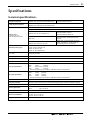
General specifications
Frequency response
20 Hz–20 kHz +1 dB, –3 dB @+4 dB into 600Ω
(GROUP OUT, AUX OUT, ST OUT, MONO OUT)
Total harmonic distortion
Less than 0.1%, @20 Hz–20 kHz, +14 dB into 600Ω
(GROUP OUT, AUX OUT, ST OUT, MONO OUT)
Input gain control: minimum
–128 dB equivalent input noise
–95 dB residual output noise (GROUP OUT, AUX OUT, ST OUT, MONO OUT)
Hum & noise
(Average, Rs=150Ω
with 20 Hz–20 kHz BPF)
–86 dB
(GROUP OUT, ST OUT, MONO OUT)
Master fader: nominal level
All channel faders: minimum
All channel assign switches: off
–81 dB
(AUX OUT)
Master fader: nominal level
All channel faders, all AUX level controls:
minimum
–64 dB (68 dB S/N)
(GROUP OUT, AUX OUT, ST OUT)
Master fader, one channel fader, AUX level
control: nominal level, Assign switch: on
One channel gain control: maximum
Maximum voltage gain
84 dB
84 dB
58 dB
58 dB
CH IN to ST OUT
CH IN to GROUP OUT
ST IN to ST OUT
ST IN to GROUP OUT
Crosstalk
(at 1 kHz)
70 dB adjacent input
70 dB input to output
CH input gain control
44 dB variable
CH input PAD
0 dB/26 dB
CH input HPF
80 Hz 12 dB/oct
CH input equalization
±15 dB maximum
HIGH
10 kHz
shelving*
MID
250 Hz–5 kHz peaking
LOW
100 Hz
shelving*
* Turn over/roll off frequency of shelving: 3 dB below maximum variable level.
ST input equalization
±15 dB maximum
HIGH
10 kHz
shelving*
MID
2.5 kHz
peaking
LOW
100 Hz
shelving*
* Turn over/roll off frequency of shelving: 3 dB below maximum variable level.
Meters
13 points LED meters x4 (GROUP 1–4 /ST L R, PFL•AFL•TAPE IN L R)
CH peak indicators
Red LED on each channel turns on when Post EQ signal reaches the level –3 dB below clipping.
Phantom power
+48 V is supplied to electrically balanced inputs.
Power requirement
USA and Canada: 120 V AC 60 Hz
Other:
230 V AC 50 Hz
Power consumption
GF24/12: 70 W, GF16/12: 70 W, GF12/12: 70 W
Dimensions (WxHxD)
GF24/12: 938×157×487 mm
GF16/12: 701×157×487 mm
GF12/12: 587×157×487 mm
Weight
GF24/12: 20 kg, GF16/12: 16 kg, GF12/12: 14 kg
• 0 dB is referenced to 0.775 Vrms.
—Owner’s Manual
22
Specifications
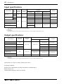
Input specifications
Input terminals
INPUT A, B
(1–20, 1–12, 1–8)
ST INPUT A, B
(21–24, 13–16, 9–12)
Gain
trim
Actual load
impedance
For use with
nominal
3 kΩ
50–600Ω Mics
&
600Ω Lines
Input level
Connector
Sensitivity†1
Nominal
Max. before clip
–86 dB (38.8 µV)
–60 dB (0.775 mV)
–40 dB (7.75 mV)
–42 dB (6.16 mV)
–16 dB (123 mV)
+4 dB (1.23 V)
MAX
–60 dB (0.775 mV)
–34 dB (15.5 mV)
–14 dB (155 mV)
MIN
–16 dB (123 mV)
+10 dB (2.45 V)
+30 dB (24.5 V)
A: Phono jack†3
B: Phone jack†3
–12 dB (195 mV)
+4 dB (1.23 V)
+20 dB (7.75 V)
Phone jack†3
–26 dBV (50.1 mV)
–10 dBV (316 mV)
+8 dBV (2.51 V)
Phono jack†3
0 dB (775 mV)
+20 dB (7.75 V)
Phone jack (I/O)†3
MAX
MIN
AUX RTN IN (1, 2)
TAPE IN (L, R)
10 kΩ
600Ω Lines
CH INSERT IN
(1–20, 1–12, 1–8)
–26 dB (38.8 mV)
ST INSERT IN (L, R)
–10 dB (245 mV)
A: XLR-3-31 type†2
B: Phone jack†2
†1. Sensitivity is the lowest level that will produce an output of +4 dB (1.23 V) or the nominal output level when the unit is set at maximum
gain. (All faders and level controls are at maximum positions.)
†2. Balanced.
†3. Unbalanced.
• When dB represents a specific voltage, 0 dB is referenced to 0.775 Vrms, 0 dBV is referenced to 1 Vrms.
Output specifications
Output terminals
Actual source
impedance
For use with
nominal
Output level
Connector
Nominal
Max. before clip
ST OUT (L, R)
150Ω
+24 dB (12.3 V)
XLR-3-32 type†1
+20 dB (7.75 V)
Phone jack†2
MONO OUT
GROUP OUT (1–4)
75Ω
AUX OUT (1–6)
150Ω
+24 dB (12.3 V)
Phone jack†1
C-R OUT (L, R)
75Ω
+20 dB (7.75 V)
Phone jack†2
–10 dBV (316 mV)
+10 dBV (3.16 V)
Phono jack†2
0 dB (775 mV)
+20 dB (7.75 V)
3 mW
100 mW
600Ω Lines
REC OUT (L, R)
CH INSERT OUT
(1–20, 1–12, 1–8)
600Ω
+4 dB (1.23 V)
10 kΩ Lines
Phone jack (I/O)†2
ST INSERT OUT (L, R)
PHONES OUT
100Ω
40Ω Phones
†1. Balanced.
†2. Unbalanced.
• When dB represents a specific voltage, 0 dB is referenced to 0.775 Vrms, 0 dBV is referenced 1 Vrms.
Specifications are subject to change without prior notice.
For European Model
Purchaser/User Information specified in EN55103-1 and EN55103-2.
Inrush Current: 3A
Conformed Environment: E1, E2, E3 and E4
—Owner’s Manual
ST phone jack†2
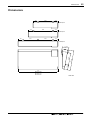
Dimensions
23
Dimensions
119
349
119
GF12/12
119
463
119
GF16/12
351
349
119
GF24/12
D: 487
300
H: 157
119
119
W:
GF24/12: 938
GF16/12: 701
GF12/12: 587
Unit: mm
—Owner’s Manual
24
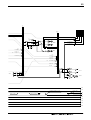
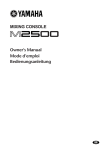
Specifications
Block/Level Diagram
PHANTOM
GROUP
AUX
1 2 3 4 1 2 3 4 5 6
+48V
INPUT A
PAD
PEAK
INSERT I/O
0dB
PHANTOM
+48V
to ST
ST
HA
3 Stage EQ
HPF
1-20
{1-12}
{1-8}
1-2
PAN
80
g
g
3-4
MID
HIGH
GAIN
LOW
26dB
INPUT B
f
g
ON
AUX 1
AUX 2
AUX 3
PRE
to Meter
AUX 4
AUX 5
PRE
to PFL/AFL
PAN
TO ST
AUX 6
PFL
GROUP OUT 1
to PFL/AFL
ST
*2,*4
HA
80
HIGH
GAIN
INPUT A
GROUP OUT 2-4:
Same as GROUP OUT 1
3 Stage EQ
HPF
MID
HA
B
LOW
*1,*3
(MONO)
AFL
to ST
PEAK
A
ON
1-2
BAL
3 Stage EQ
HPF
80
3-4
*1,*3
INPUT B
AUX 1
*2,*4
AUX 2
AUX 3
No. GF12/12 GF16/12
GF24/12
*1
9L
13L
21L
*2
10R
14R
22R
*3
11L
15L
23L
*4
12R
16R
24R
PRE
AUX 4
AUX 5
PFL
to PFL/AFL
PRE
AUX 6
AUX OUT 1
L
(MONO)
AUX RETURN 1
R
to PFL/AFL
GROUP 1
AFL
GROUP 2
AUX OUT 2-6:
Same as AUX OUT 1
AUX 1
AUX 2
to ST
ST
PFL
L
(MONO)
AUX RETURN 2
R
to PFL/AFL
GROUP 3
GROUP 4
AUX 3
AUX 4
ST
PFL
to ST
to PFL/AFL
+20 dB
+10 dB
PAD 26 dB
GAIN Min (+10 dB)
ST INPUT
GAIN Min (+10 dB)
AUX RETURN (+4 dB)
GROUP OUT, AUX OUT (+4 dB)
INSERT I/O (0 dB)
0 dB
AUX (–6 dB)
–10 dB
PAD 0 dB
GAIN Min (–16 dB)
Ch Fader
–20 dB
–30 dB
PAD 26 dB
GAIN Max (–34 dB)
ST INPUT
GAIN Max (–30dB)
–40 dB
–50 dB
–60 dB
PAD 0 dB
GAIN Max (–60 dB)
—Owner’s Manual
GROUP, AUX
25
ST
L R
PFL/AFL
L R
from GROUP OUT 1
ST
INSERT
I/O L
from GROUP OUT 2
L
ST
INSERT
I/O R
from GROUP OUT 3
STEREO
OUT
from GROUP OUT 4
R
METER SELECT
L
PAD
1-20
Ch Input {1-12}
{1-8}
from
REC OUT
R
AFL
(L)
(R)
MONO
OUT
POST MONO
Ch Input *1,*3
Ch Input *2,*4
AUX RETURN 1, 2
L
R
1-20
Ch Input {1-12}
{1-8}
Ch Input *1,*3
Ch Input *2,*4
from
AUX RETURN 1, 2
L
R
GROUP OUT
AUX OUT
BA
TAPE IN
L
C-R MONITOR
LEVEL
C-R OUT
BA
R
L
TAPE IN
ST
ON
BA
R
PHONES
LEVEL
PHONES
BA
+20 dB
+10 dB
STEREO OUT, MONO OUT (+4 dB)
C-R OUT (+4 dB)
ST INSERT I/O (0 dB)
TAPE IN (–10 dBV)
0 dB
PHONES (3 mW, 40*)
REC OUT (–10 dBV)
–10 dB
MONO
–20 dB
–30 dB
–40 dB
–50 dB
–60 dB
—Owner’s Manual
YAMAHA CORPORATION
V329640 R3 1 IP 32
NP Printed in Taiwan
Pro Audio Division, #18/3
P.O. Box 3, Hamamatsu, 430-8651, Japan