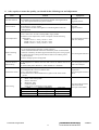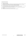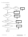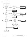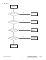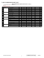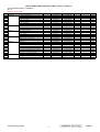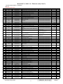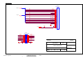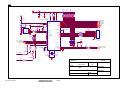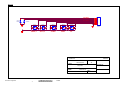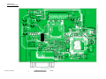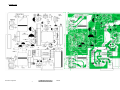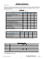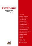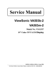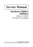
1
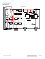
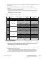
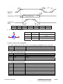
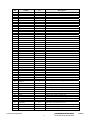
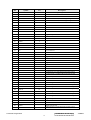
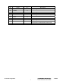
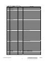
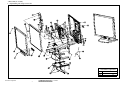
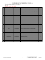
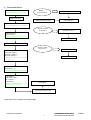
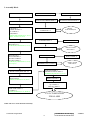
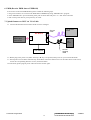
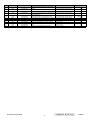
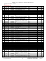
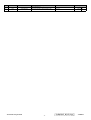
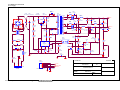
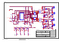
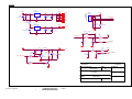
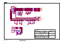
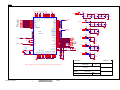
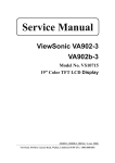
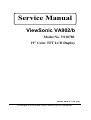
Service Manual ViewSonic VA902/b Model No. VS10780 19” Color TFT LCD Display (VA902/b_SM Rev. 1a Oct. 2005 ) ViewSonic 381 Brea Canyon Road, Walnut, California 91789 USA - (800) 888-8583 Copyright Copyright ¤ 2005 by ViewSonic Corporation. All rights reserved. No part of this publication may be reproduced, transmitted, transcribed, stored in a retrieval system, or translated into any language or computer language, in any form or by any means, electronic, mechanical, magnetic, optical, chemical, manual or otherwise, without the prior written permission of ViewSonic Corporation. Disclaimer ViewSonic makes no representations or warranties, either expressed or implied, with respect to the contents hereof and specifically disclaims any warranty of merchantability or fitness for any particular purpose. Further, ViewSonic reserves the right to revise this publication and to make changes from time to time in the contents hereof without obligation of ViewSonic to notify any person of such revision or changes. Trademarks Optiquest is a registered trademark of ViewSonic Corporation. ViewSonic is a registered trademark of ViewSonic Corporation. All other trademarks used within this document are the property of their respective owners. Revision History Revision SM Editing Date 1a 10/20/2005 Description of Changes ECR Number Editor G. Han Initial Release Confidential - Do Not Copy ViewSonic Corporation i VA902/b TABLE OF CONTENTS 1. Precautions and Safety Notices 1 2. Service Tools & Equipment Required 3 3. Circuit Theory 4 4. Disassembly & Assembly 15 5. Test and Adjustment 19 6. Troubleshooting 24 7. Recommended Parts List 32 8. Schematic Diagrams 42 9. PCB Layout Diagrams 46 Confidential - Do Not Copy ViewSonic Corporation ii VA902/b 1. Precautions and Safety Notices 1. Appropriate Operation (1) (2) (3) (4) (5) (6) (7) (8) (9) (10) Turn off the product before cleaning. Use only a dry soft cloth when cleaning the LCD panel surface. Use a soft cloth soaked with mild detergent to clean the display housing. Use only a high quality, safety approved AC/DC power cord. Disconnect the power plug from the AC outlet if the product will not be used for a long period of time. If smoke, abnormal noise, or strange odor is present, immediately switch the LCD display off. Do not touch the LCD panel surface with sharp or hard objects. Do not place heavy objects on the LCD display, video cable, or power cord. Do not use abrasive cleaners, waxes or solvents for your cleaning. Do not operate the product under the following conditions: - Extremely hot, cold or humid environment. - Areas containing excessive dust and dirt. - Near any appliance generating a strong magnetic field. - In direct sunlight. 2. Caution No modification of any circuit should be attempted. Service work should only be performed after you are thoroughly familiar with all of the following safety checks and servicing guidelines. 3. Safety Check Care should be taken while servicing this LCD display. Because of the high voltage used in the inverter circuit, the voltage is exposed in such areas as the associated transformer circuits. 4. LCD Module Handling Precautions 4.1 Handling Precautions (1) Since front polarizer is easily damaged, pay attention not to scratch it. (2) Be sure to turn off power supply when connecting or disconnecting input connector. (3) Wipe off water drops immediately. Long contact with water may cause discoloration or spots. (4) When the panel surface is soiled, wipe it with absorbent cotton or other soft cloth. (5) Since the panel is made of glass, it may break or crack if dropped or bumped on hard surface. (6) Since CMOS LSI is used in this module, take care of static electricity and ensure human earth when handling. (7) Do not open or modify the Module Assembly. (8) Do not press the reflector sheet at the back of the module in any direction. (9) In the event that a Module must be put back into the packing container slot after it was taken out of the container, do not press the center of the CCFL Reflector edge. Instead, press at the far ends of the CFL Reflector edge softly. Otherwise the TFT Module may be damaged. (10) At the insertion or removal of the Signal Interface Connector, be sure not to rotate or tilt the Interface Connector of the TFT Module. Confidential - Do Not Copy ViewSonic Corporation 1 VA902/b (11) After installation of the TFT Module into an enclosure (LCD monitor housing, for example), do not twist or bend the TFT Module even momentarily. When designing the enclosure, it should be taken into consideration that no bending/twisting forces may be applied to the TFT Module from outside. Otherwise the TFT Module may be damaged. (12) The cold cathode fluorescent lamp in the LCD contains a small amount of mercury. Please follow local ordinances or regulations for disposal. (13) The LCD module contains a small amount of materials having no flammability grade. The LCD module should be supplied with power that complies with the requirements of Limited Power Source (IEC60950 or UL1950), or an exemption should be applied for. (14) The LCD module is designed so that the CCFL in it is supplied by a Limited Current Circuit (IEC60950 or UL1950). Do not connect the CCFL to a Hazardous Voltage Circuit. Confidential - Do Not Copy ViewSonic Corporation 2 VA902/b 2. SERVICE TOOLS & EQUIPMENT REQUIRED 1. SIGNAL GENERATOR 2. MULTIMETER 3. SCREW DRIVER 4. OSCILLOSCOPE 5. Soldering IRON 6. SOLDER 7. VGA Cable (Black, 15pins point to point) 8. Color Analyzer 9. ISP Board 10. EDID Board 11. FOXISP. EXE file 12. EDID program file 13. Power Adapter output 5V/2A Confidential - Do Not Copy ViewSonic Corporation 3 VA902/b 3. CIRCUIT THEORY 1. Block Diagram Block Diagram TFT LCD Panel 19" 12V Lamp2 Panel Interface 2 Rectifier & Filter Circuit 5V Power Lamp1 1 5V AP2301 PMBT3906 LDO 5V-3.3V 5V-1.8V 24C16 Power Transformer Feedback OVP Transformer1 Panel Enable On/Off Brightness On/Off AOP605L MCU W78E65p Rectifier & Filter Circuit OZ9910 Scaler TSU16AK Brightness XTAL2 14.318MHz LTV817 AOP605L XTAL1 22.118MHz Transformer2 Open Protection AC Line Filter 4 3 3 2 TOP246Y OPP/OCP 24C02 1 4 Lamp3 Lamp4 AC Socket AC Input 90V-264V Keypad Connector VGA Connector Keyboard VGA Input Confidential - Do Not Copy ViewSonic Corporation 4 VA902/b 2. Electronic Circuit Theory 2.1 Switching Mode Power Supply 2.1.1 AC Current Input Circuit P801 is a connector for connecting AC Power. F801 is a fuse to protect all the circuit. AC input voltage is from 100V to 240V. R820 and R821 joined between two inputting main circuit to prevent man from shock. L801 is used to clear up low frequency wave. C801 and C806 are used to discharge the waves that L801 produced. High frequency waves are damped by C801 and C806. D801 is a rectifier which composed of 4 build-in diodes, it inverts AC to DC. 2.1.2 High Voltage to Low Voltage Control Circuit C805 is used to smooth the wave from rectifier. IC802 is a highly integrated PWM controller, which build-in a power MOSFET. When rectified DC high voltage is applied to the DRAIN pin during start-up, the MOSFET is off initially, and the CONTROL pin capacitor is charged through a switched high voltage current source connected internally between the DRAIN and CONTROL pins. When the CONTROL pin voltage Vc reaches approximately 5.8V, the control circuitry is activated and the soft-start begins. The soft-start circuit gradually increases the duty cycle of the MOSFET from zero to the maximum value over approximately 10ms. If no external feedback/supply current is fed into the CONTROL pin by the end of the soft-start, the high voltage current source is turned off and the CONTROL pin will start discharging in response to the supply current drawn by the control circuitry. Resistor R803, R807, R824 and R825 are for line over voltage shut-down (OVP) and line under-voltage detection (UVP).Resistors R801, R805, R822, and R823 are for external current limit adjustment, and used to reduce the current limit externally to a value close to the operating peak current of primary about 1.35A. The mean is power will protected when the primary current over about 1.35A. When PWM is turned off, the main current flow will be consumed through D804 and ZD802, This will prevent MOSFET which built-in IC802 from being damaged under large current impulse and voltage spike. D806 and C815 provide internal Auxiliary current to CONTROL pin during normal operation. In addition, error amplifier and feedback current to the CONTROL pin are for duty cycle control. 2.1.3 DC_5V and DC_14V Output Circuit For DC 5V, D805 is used to rectify the inducted current. R806 and C811 are used to store energy when current is reversed. The parts including C812, C814, C822, C821, B801 and L803 are used to smooth the current waves. For DC 14V, D803 is used to rectify the inducted current. R802 and C802 are used to store energy when current is reversed. The parts including C808, C810 and L802 are used to smooth the current waves. 2.1.4 Feedback and OVP Protect Circuit Pin R of IC803 is supplied 2.5V stable voltage. It is connected to 5V and 14V output through R811, R810 and R818. R811, R810 and R818 are output sampling resistor. When the sampling voltage more than 2.5V or less than 2.5V, feedback current of IC802 will change, this can change the voltage from transformer T801. For 5VDC output OVP, ZD803 is a zener diode, when 5V output voltage becomes up to 5.6V, the zener current cause R819 voltage become up to 0.7V, Q801 is triggered and OVP starts. For 14VDC output OVP, ZD804 is a Zener Diode, when 14V output voltage becomes up to 16V, the zener current cause R819 voltage become up to 0.7V, Q801 is triggered and OVP starts. The collector current of Q801 is used to make build-in diode light. FB Current of IC802 will be changed; it can change the voltage from T801. Q802, R827, R828 and ZD801 make up of dummy loading circuit. For start-up sequence, during 5V output take place high loading first, this dummy loading circuit operated to insure 14V not be increased. 2. 2 Inverter circuit 2.2.1 Low voltage to high voltage circuit 14VDC supplies the power to IC501 through F501; the control signals that BRIGHTNESS and ON/OFF come from I/F board. ON/OFF signal connect to pin8 of IC501 and makes IC501 enabled. BRIGHTNESS is connected to pin7 of IC501 to adjust the panel luminance. R524, R529, C505 make up of a delay-time circuit and R528, R523, R524 make up of a voltage divided circuit. C504 is used to filter the high frequency noise. The operation frequency is determined by R522 and C529. For BURST MODE, its Confidential - Do Not Copy ViewSonic Corporation 5 VA902/b dimming frequency is determined by R527 and C506. C502 is used for soft start and compensation, C502, C528 are used to filter noise. The output drives, including NDR4, NDRV2, PDRV3, PDRV1 (pins1, 3, 15, 16 respectively), generate a square pulses to drive MOSFET U501, U502. And U501, U502 works as full-bridge topology, it is high efficient, zero voltage switch. During start up, VSEN (pin9) detects the voltage at the transformer secondary. When VSEN reaches 3.0V, the output voltage is regulated. If no current is detected for around 1.5 seconds, IC501 will shut down. The current flowing through CCFL is detected and regulated through sense resistor R509, R511. The feedback voltage through R506, R507, and C508 connected to Pin11 (ISEN), and then compared with a reference voltage (1.5V) via a current amplifier, resulting in PWM drive outputs to full-bridge switches. 2.2.2 Protection circuit Over Voltage Protection: R501and R502 are connected in high voltage output connector, the divided AC voltage is inverted DC voltage through D508, R505 and C507are used to rectify wave & dump noise. Then the voltage signal reaches Pin9 VSEN of IC501, when the voltage changes, build-in PWM of IC501 will adjust output voltage. Open Lamp Protection: In normal operation, the resistors R510, R511, R512, R509 are sensed a high level AC voltage, the AC signal IS1 invert DC voltage through D509, R515, C533, and the high level DC voltage reaches the gate pin of Q502, similarly, the gate pin of Q503, Q504, Q505 has high level DC voltage. So the gate pin of Q501 has a low level voltage, and the IC501 is normal operation. Once one of signal IS1, IS2, IS3, and IS4 is low, the voltages of Q501 gate pin is high level, and make the voltage of ISEN low level, the IC501 will shut down. 2.3 I/F Board Circuit 2.3.1 Power Input +5V is from the power board and supply for U101(FS8860-18PJ)﹑U102(FS8860-33PJ)﹑ U105(MCU:W78E65P) and panel. +3.3V output is generated from +5V through C169 and C102 filtering, and U102 outputs. +3.3V is used for U104 (Scaler: TSU16AK). +1.8V output is generated from +5V through C169, C105 and C102 filtering, and U101 outputs. +1.8V is also used for U104. 2.3.2 MCU (W78E65P) VDD is +5V and its frequency of XTAL1 is 22.1184MHz. U105 #2 is defined as panel-enable. When the I/O port is low, Q101 and Q102 are conducted. And then after C109 and C110 filtering, obtain the voltage of VLCD, which will be connected to CN103. U105 #3 is defined as CCFL-enable. When the I/O port is low, Q103 is pulled up and the backlights are on; When the I/O port is high, Q103 is conducted and the backlights are off. U105 #4 is defined as DET-VGA, connected with CN102 #5. U105 #14, #36, #37, #38, #39, #40, #41, #42, #43 are the communications with U104 (Scaler), which are connected to #72, #31, #78, #77, #30, #70, #71, #69, #32 of Scaler. U105 #43 outputs reset signal to U104 (Scaler). U106 is EEPROM used for saving EDID data, which is connected by SCL and SDA pins with #16 and #17 of MCU. Connect #12 to #26 of U105 for ISP. 2.3.3 Scaler (TSU16AK) The frequency of XTAL2 is 14.318MHz. U104 #1, #102-#103, #106-#113, #118-#125, #128 output LVDS digital data of 8 bit to panel control circuit through CN103. U104 #73 generates a PWM waveform by regulating the duty to control the brightness of the backlights. U104 #30-#32, #69-#72, #77-#78 are the communications with U105 (MCU) that are connected to #36-#43 of MCU. These communications include HWRESET, CSZ/ALE, SCL/RDZ, SDA/WRZ, and AD0-AD3. 2.3.4 VGA Input Signal R, G, B, SOG input through CN102 #1, #2, #3, and C115, C116, C117 and C118 filtering the high frequency noise. Signal HSYNC and VSYNC input through CN102 #13 and #14, and C119, R119, C120, R120 filtering. Then the analog signal enters U104, and then U104 deals with it internally. In addition, TVS101, TVS102, TVS103 (the three are BAV99), TVS104, TVS105, TVS106, TVS107 (they are constant voltage diode of 5V6) are ESD protector. Signal DDC-SCL inputs via CN102 #15, and then passes through TVS107 for ESD protection, goes into EDID EEPROM IC U103. Signal DDC-SDA inputs via CN102 #12, and then passes through TVS106 for ESD protection, goes into EDID EEPROM IC U103. CN102 #5 is defined as cable detect pin, this detector realizes via R107 and U105 #4. The PC-5V of U103 is supplied by PC via CN103 #9 with D103 for ESD protection, or supplied by Monitor self via D104.U103 is an EEPROM IC, which is a kind of memory and used for saving EDID data. 2.3.5 Button Control Button “Key-Power” is defined as power on/off, which is connected to U105 #24 through CN106 #4. Confidential - Do Not Copy ViewSonic Corporation 6 VA902/b Button “Key-2” is defined as two functions of selecting and adjustment, which is connected to U105 #25 through CN106 #1. Button “Key-Up” is defined as plus, which is connected to U105 #26 through CN106 #3. Button “Key-Down” is defined as minus, which is connected to U105 #27 through CN106 #5. Button “Key-1” is defined as two functions of menu and exit, which is connected to U105 #28 through CN106 #2. LED indicator on the front bezel is defined as follows: a. When press button “Key-Power”, U105 #6 is pulled down and U105 #7 is pulled high, so Q104 is conducted and the LED indicator is green. b. When in power-saving mode, U105 #6 is pulled high and U105 #7 is pulled down, so Q105 is conducted and the LED indicator is orange. 3. FACTORY PRESET TIMING TABLE Item Resolution 1 2 3 4 5 6 7 8 9 10 11 12 13 14 15 16 17 18 19 20 21 22 23 24 25 640 x 350 640 x 400 640 x 400 640 x 480 720 x 400 800 x 600 832 x 624 1024 x 768 1152 x 870 1280 x 1024 1280 x 720 H-Freq. (KHz) 31.5kHz 31.5kHz 31.5kHz 24.7kHz 31.5kHz 35.0kHz 37.9kHz 37.5kHz 43.27kHz 31.5kHz 35.1kHz 37.9kHz 48.1kHz 46.9kHz 53.7kHz 49.7kHz 48.4kHz 56.5kHz 58.1kHz 60.0kHz 68.67kHz 68.6kHz 63.4kHz 79.97kHz 45kHz V-Freq. (Hz) 70Hz 60Hz 70Hz 50Hz 60Hz 67Hz 72Hz, 75Hz, 85Hz 70Hz 56Hz 60Hz 72Hz 75Hz 85Hz 75Hz 60Hz 70Hz 72Hz 75Hz 85Hz 75Hz 60Hz 75Hz 60Hz Dot Clock (MHz) 25.2 25.2 25.2 19.8 25.2 30.2 31.5 31.5 36.0 28.3 36.0 40.0 50.0 49.5 56.3 57.3 65.0 75.0 78.5 78.8 94.5 100 108 135 74.2 4. Power On/Off Sequence 4.1 Hardware Power ON When power cord is plugged into AC socket, SMPS starts work and provides U105 and U106 with VCC5V. When VCPU inputs to U105, U105 resets circuit active, sets U105 all registers to preset modes, and then U105 #43 sends out a HWRESET signal voltage to reset U104, and then monitor goes into stand-by mode. That means hardware power on has been completed. 4.2 Software Power ON/OFF When press power key, U105 #24 recieves low pulse, and sends out “Power on/off” order back to U104, and then U104 will do the power on/off. If Power ON, U105 #6 (LED_Green) will send out High potential, and then LED green on. If Power OFF, U105 #7 (LED_Orange) will send out High potential, and then LED Orange on. The Panel_Vcc, Backlight_En, CLK/DATA output to panel will follow the following sequency. Confidential - Do Not Copy ViewSonic Corporation 7 VA902/b T1 (ms) 0.1~10 T2 (ms) 0~10 T3 (ms) >200 T4 (ms) >100 T5 (ms) 0~50 T6 (ms) 0.1~10 T7 (ms) >1000 3 5. AC Outlet Pin Assignment 2 1 Pin Symbol Description 1 L Live 2 N Neutral 3 E GND P801 6. Inner Connector Pin Assignment 6.1 CN501, CN502, CN503, CN504 (Connect to Panel Backlight, SM02B-BHSS-1-TB or equivalent) Pin Symbol Description 1 2 H.V. L.V. High voltage for lamp Low voltage for lamp 6.2 CN101 (Power BD to Interface BD) Pin No. 1,2 3,6 4 5 Symbol +5V (VCC5V) GND BRIGHTNESS ON/OFF Description +5.2V output Ground Brightness Control CCFL on/off Control 6.3 CN106 (Interface BD to Keypad) Pin No. Symbol 1 2 3 4 5 6 7 8 KEY_SELECT/AUTO KEY_MENU/EXIT KEY_UP KEY_POWER KEY_DOWN LED_GREEN GND LED_ORANGE Description Select control and auto adjustment control OSD page selection and exit OSD “▲” control to adjust value to increase DC power on/off control OSD “▼” control to adjust value to decrease Green LED lighting control Ground Orange LED lighting control Confidential - Do Not Copy ViewSonic Corporation 8 VA902/b 6.4 CN103 (Connect I/F BD to panel, FI-X30S-H or Equivalent) Pin No. Symbol Function 1 2 3 4 5 6 7 8 9 10 11 12 13 14 15 16 17 18 19 20 21 22 23 24 25 26 27 28 29 30 RXO0RXO0+ RXO1RXO1+ RXO2RXO2+ GND RXOCRXOC+ RXO3RXO3+ RXE0RXE0+ GND RXE1RXE1+ GND RXE2RXE2+ RXECRXEC+ RXE3RXE3+ GND GND GND GND minus signal of odd channel 0(LVDS) plus signal of odd channel 0(LVDS) minus signal of odd channel 1(LVDS) plus signal of odd channel 1(LVDS) minus signal of odd channel 2(LVDS) plus signal of odd channel 2(LVDS) Ground minus signal of odd clock channel (LVDS) plus signal of odd clock channel (LVDS) minus signal of odd channel 3(LVDS) plus signal of odd channel 3(LVDS) minus signal of even channel 0(LVDS) plus signal of even channel 0(LVDS) Ground minus signal of even channel 1(LVDS) plus signal of even channel 1(LVDS) Ground minus signal of even channel 2(LVDS) plus signal of even channel 2(LVDS) minus signal of even clock channel (LVDS) plus signal of even clock channel (LVDS) minus signal of even channel 3(LVDS) plus signal of even channel 3(LVDS) Ground Ground Ground or Open Ground VCC VCC VCC Power supply (5.0 V) Power supply (5.0 V) Power supply (5.0 V) 6.5 CN102 (D-SUB Connector) Pin 1 2 3 4 5 Symbol Red video input Green video input Blue video input NC Cable Detect Pin 6 7 8 9 10 Symbol Red GND Green GND Blue GND +5V(from PC) GND Pin 11 12 13 14 15 Symbol NC Serial data (SDA) H / H+V SYNC VSYNC Data clock line (SCL) Confidential - Do Not Copy ViewSonic Corporation 9 VA902/b 7. Key Parts Pin Assignment 7.1 IC802 (TOP246Y, Power Control IC) Pin Symbol I/O 1 2 3 4 5 6 C L X S F D I I I O I I Description Control Line Sense External Current Limit Source of MOSFET(GND) Frequency Drain of MOSFET 7.2 IC501 (OZ9910G, CCFL inverter controller IC) Pin No. Symbol I/O Description 1 NDRV4 O Bottom MOSFET gate drive output in dual forward converter 2 PGND High-current power ground 3 NDRV2 O Bottom MOSFET gate drive output in dual forward converter 4 GNDA 5 6 7 8 CT LCT ADJ ENA 9 Low-current signal ground Timing capacitor of high frequency oscillator Timing capacitor of set LPWM frequency Control command input –DC Enable input VSEN I I I I I 10 CMP_SST I Soft start and loop compensation capacitor 11 ISEN I Current sense feedback 12 VREF O Reference voltage output 13 VIN I Supply voltage for IC 14 HSB I High side driver buffer output 15 PDRV3 Top MOSFET gate drive output in dual forward converter 16 PDRV1 O O Voltage sense feedback Top MOSFET gate drive output in dual forward converter 7.3 U104 (TSU16AK) Pin 1 2 3 4 5 6 7 8 9 10 11 12 13 14 15 16 17 18 19 Symbol LVBOM GND BYPASS NC NC BUSTYPE NC NC NC GND VDDP NC NC NC NC NC NC VDDC GND I/O Description B-Link Negative LVDS Differential Data Output Ground For External Bypass Capacitor Not connected Not connected Low : Serial bus; High : Direct bus Not connected Not connected Not connected Ground Digital Output Power Not connected Not connected Not connected Not connected Not connected Not connected Digital Core Power Ground O IN O I Confidential - Do Not Copy ViewSonic Corporation 10 VA902/b Pin Symbol I/O Description 20 21 22 23 24 25 26 27 28 29 30 31 32 33 34 35 36 37 38 39 40 41 42 43 44 45 46 47 48 49 50 51 52 53 54 55 56 57 58 59 GND VDDP NC NC NC NC NC NC NC NC AD0 AD3 HWRESET XIN XOUT AVDD_MPLL GND HSYNC0 VSYNC0 GND NC NC GND NC NC VDD_ADC NC NC GND NC NC VDD_ADC REXT AVDD PLL GND AVDD ADC GND BINOM BINO GINOM Ground Digital Output Power Not connected Not connected Not connected Not connected Not connected Not connected Not connected Not connected DDR direct bus AD0; 4mA driving strength DDR direct bus AD3; 4mA driving strength Hardware reset; active high Crystal Oscillator Input Crystal Oscillator Output MPLL Power Ground Analog HSYNC input Analog VSYNC input Ground Not connected Not connected Ground Not connected Not connected ADC Power Not connected Not connected Ground Not connected Not connected ADC Power External resistor 390 ohm to AVDD ADC PLL Power Ground ADC Power Ground Reference ground for analog blue input Analog blue input Reference ground for analog green input 60 61 62 63 64 65 66 67 68 69 70 GINO SOGIN0 RINOM RINO GND AVDD_ADC REFP REFM GND ALE/CS WRZ/SDA 71 RDZ/SCL I DDR direct bus RDZ; active low 72 73 INT PWM0 O O CPU interrupt; 4mA driving strength PWM0; 4mA driving strength O I/O I/O I I O I I I I I I I I I Analog green input I I I I Sync-on-green input Reference ground for analog red input Analog red input Ground ADC Power Internal ADC top de-coupling pin Internal ADC bottom de-coupling pin Ground DDR direct bus ALE; active high DDR direct bus WRZ; active low I I I/O Confidential - Do Not Copy ViewSonic Corporation 11 VA902/b Pin Symbol I/O Description 74 75 76 77 PWM1 NC NC AD1 O I/O PWM1; 4mA driving strength Not connected Not connected DDR direct bus AD1; 8mA driving strength 78 AD2 I/O DDR direct bus AD2; 8mA driving strength 79 NC Not connected 80 NC Not connected 81 NC Not connected 82 NC Not connected 83 NC 84 VDDP Not connected Digital Output Power 85 GND Ground 86 GND 87 VDDC Ground Digital Core Power 88 NC Not connected 89 NC Not connected 90 NC Not connected 91 92 93 94 95 96 97 98 99 100 101 102 NC NC NC VDDP GND GND VDDC NC NC NC NC LVA3P 103 104 105 106 LVA3M VDDP GND LVACKP O O Not connected Not connected Not connected Digital Output Power Ground Ground Digital Core Power Not connected Not connected Not connected Not connected A-Link Positive LVDS Differential Data Output A-Link Negative LVDS Differential Data Output 107 LVACKM O Digital Output Power Ground A-Link Positive LVDS Differential Clock Output A-Link Negative LVDS Differential Clock Output 108 LVA2P O A-Link Positive LVDS Differential Data Output 109 LVA2M O A-Link Negative LVDS Differential Data Output 110 LVA1P O A-Link Positive LVDS Differential Data Output 111 LVA1M O A-Link Negative LVDS Differential Data Output 112 LVA0P O A-Link Positive LVDS Differential Data Output 113 LVA0M O A-Link Negative LVDS Differential Data Output 114 VDDP O Digital Output Power 115 GND Ground 116 GND Ground 117 VDDC 118 LVB3P Digital Core Power B-Link Positive LVDS Differential Data Output O I O I O O O Confidential - Do Not Copy ViewSonic Corporation 12 VA902/b Pin Symbol I/O Description 119 LVB3M O 120 LVBCKP O B-Link Negative LVDS Differential Data Output B-Link Positive LVDS Differential Clock Output 121 LVBCKM O B-Link Negative LVDS Differential Clock Output 122 LVB2P O B-Link Positive LVDS Differential Data Output 123 LVB2M O B-Link Negative LVDS Differential Data Output 124 LVB1P O B-Link Positive LVDS Differential Data Output 125 LVB1M O B-Link Negative LVDS Differential Data Output 126 VDDP O Digital Output Power 127 GND 128 LVBOP O Ground B-Link Positive LVDS Differential Data Output Confidential - Do Not Copy ViewSonic Corporation 13 VA902/b 7.4 U105 (Micro-controller: W78E65P-40) Pin Symbol I/O 1 P4.2/INT3 2 P1,0/T2 O 3 P1.1/T2EX O 4 P1.2 I 5 P1.3/PWM0 O 6 P1.4/PWM1 O 7 P1.5/PWM2 O 8 P1.6/PWM3 9 P1.7/PWM4 10 11 12 13 14 15 16 17 18 19 20 21 22 23 24 25 26 27 28 29 30 31 32 33 34 35 36 37 38 39 40 41 42 43 44 RST P3.0/RXD P4.3/INT2 P3.1/TXD P3.2/INT0 P3.3/INT1 P3.4/T0 P3.5/T1 P3.6/WR P3.7/RD XTAL2 XTAL1 GND P4.0 P2.0/A8 P2.1/A9 P2.2/A10 P2.3/A11 P2.4/A12 P2.5/A13 P2.6/A14 P2.7/A15 PSEN ALE P4.1 EA P0.7/AD7 P0.6/AD6 P0.5/AD5 P0.4/AD4 P0.3/AD3 P0.2/AD2 P0.1/AD1 P0.0/AD0 +5V Description A bi-directional I/O port with alternate function. Enable panel power on Enable CCFL work VGA cable detection provide alternated function of PWM Volume provide alternated function of PWM Green LED provide alternated function of PWM Orange LED Function is the same as that of standard 8052 Function is the same as that of standard 8052 I Reset control pin SCL line of I2C for EDID, debug function PORT 4: A bi-directional I/O port with alternate SDA line of I2C for EDID, debug function Interrupt request control pin Shut Down Volume Mute I O O I/O SCL line of I2C communication with EEPROM SDA line of I2C communication with EEPROM DVI cable detection EEPROM write protection control for DVI EDID I O Crystal 22.1184MHz In Crystal 22.1184MHz out Sink voltage ground A bi-directional I/O port with alternate function. DC power on/off control OSD “►” control to adjust value to increase OSD “◄” control to adjust value to decrease Selection of menu command listed OSD page selection Auto adjustment control A bi-directional I/O port with internal pull-ups A bi-directional I/O port with internal pull-ups Program Store Enable Address Latch Enable A bi-directional I/O port with alternate function External Access Enable I I/O I/O I/O I/O I/O I/O I/O O I DDR Direct Bus Communication with Scaler DDR Direct Bus Communication with Scaler DDR Direct Bus Communication with Scaler DDR Direct Bus Communication with Scaler WRZ line of DDR Direct Bus RDZ line of DDR Direct Bus ALE line of DDR Direct Bus Hardware reset to Scaler +5V for MCU working voltage Confidential - Do Not Copy ViewSonic Corporation 14 VA902/b 4. Disassembly & Assembly 1. Exploded Diagram and Spare Parts List ViewSonic Corporation Model Title Date Confidential - Do Not Copy ViewSonic Corporation 15 VA902/b Rev: EXPLODED PARTS LIST (VA902/b-1) ViewSonic Model Number: VS10780-1W Rev: 1a Serial No. Prefix: PSS / PSW Item ViewSonic P/N 1 C-00003659/C-00003677 1-1 #N/A 1-2 #N/A 1-3 #N/A 1-4 #N/A 1-5 #N/A 2 #N/A 2-1 2-2 B-00003172 2-3 #N/A 2-4 #N/A 2-5 2-6 2-7 HW-00003169 2-8 HW-00003171 2-9 2-10 2-11 2-12 #N/A 2-13 #N/A 2-14 M-00003165 3 C-00003660 3-1 #N/A 3-2 #N/A 3-3 #N/A 4 C-00003658 4-1 #N/A 4-2 #N/A 4-3 HW-00003667 4-4 PL-00003053 5 C-00003657 6 HW-00003664 7 HW-00003663 8 #N/A 9 HW-00003665 10 HW-00003167 11 HW-00003666 12 Ref. P/N 714030002500/10 506102000400 506102000300 501010202900/10 501120101500 501030202200 714072841100 502090301300 502020101700 502020101710 509146305300 509000000700 511100001500 506381000700 505040202000 714050002500 501020203500 506102000500 502080300300 714020002500 501240201200 502170100500 509112605300 503020002600 501020203400 502060000110 502060000100 505040202100 509112612501 509212610300 509142716500 Description Q'ty Bezel Sub-assm,VA902/b 1 LOGO PLATE,VIEWSONIC,LE1709(THREE BIRDS) 1 LOGO PLATE, VIEWSONIC,LE1709 1 1 BEZEL,FORNT,LE1909(Silver877C)/(Midnight Gray) LENS,LE1909 1 BUTTON,FUNCTION KEY,LE1909 1 Panel Sub-Ass'y VA902/b HST 1 Panel HST 1 CHASSIS,LE1709 1 BRACKET,LEFT,LE1909 1 BRACKET,RIGHT,LE1909 1 IF BOARD ASS'Y 1 POWER BOARD ASS'Y 1 SCREW,PW,CROSS,W/WAS,M3*5,NI 14 BOLT,#4-40x11.8,NI 2 LVDS CABLE LE1909 1 1 KEYPAD CABLE LE1909 HRN ASS'Y 1P 157MM BLACK,UL 1007#20 1 SADDLE FOR CABLE 1 ACE TAPE,30000*45MM,3000PCS/FOIL 1/3000 INSULATOR,MYLAR,L79.9xW62.7MM,CHASSIS,LE1708 1 BACK SUB-ASS'Y 1 COVER,BACK,LE1909(MIDNIGHT GRAY) 1 LOGO PLATE,VIEWSONIC,LE1709(ELLIPSE) 1 SUPPORT VESA LE1709 1 BASE SUB-ASS'Y 1 BASE,LE1909(MIDNIGHT GRAY) 1 PLATE,BASE,LE1909 1 SCREW,P,CROSS,P.T-4*5,NI 2 RUBBER,FOOT,OD14xT2.5MM,3M,LE1909 5 COVER,HINGE,LE1909 2 HINGE,RIGHT,LE1909 1 HINGE,LEFT,LE1909 1 INSULATOR,MYLAR,L35xW16MM,HINGE LEFT,LE1909 1 SCREW,P,CROSS,T.T-4*12,BLK(HEAD 7.8MM) 4 SCREW,F,CROSS,T.T-4*10,NI 4 SCREW,P,CROSS W/WAS,T.T-5*16,BLACK 4 KEYPAD ASSM 1 Confidential Do Not Copy ViewSonic Corporation 16 VA902/b 2. Disassembly Block BEZEL SUB-ASSM(G/S ) BASE SUB-ASSM *1 (SCREW,P,CROSS,M5*16, Ni*4) BUTTON FUNCTION KEY*1 HINGE COVER*2 FRONT BEZEL (G/S)*1 LED LENS*1 BEZEL SUB-ASSM *1 (SCREW,P,CROSS,T4*12, BLK*4) BACK COVER SUB-ASS’Y SUPPORT VESA *1 HINGE,RIGHT*1 HINGE,LEFT*1 (SCREW,F,CROSS,T4*10, Ni*4) BACK COVER *1 BACK COVER SUB-ASS’Y*1 BASE COVER SUB-ASS’Y BRACKET_R*1 GROUND WIRE*1 KEYPAD CABEL*1 KEYPAD ASSM*1 (SCREW,PW,CROSS,M3*5, Ni*4) (Ace tape*1) PLATE BASE *1 BASE COVER *1 HSD or QDI PANEL*1 BRACKET_L*1 (SCREW,PW,CROSS,M3*5, Ni*4) IF BOARD*1 POWER BOARD*1 FFC CABLE*1 CLIP,WIRE*1 (SCREW,PW,CROSS,M3*5, Ni*4) (BOLT, #4-40x11.8, Ni*2) CHASSIS*1 INSULATOR,MYLAR*1 NOTE: The arrow is the direction of disassembly. Confidential - Do Not Copy ViewSonic Corporation 17 VA902/b 3. Assembly Block CHASSIS*1 FRONT BEZEL (G/S)*1 LED LENS*1 LOGO PLATE,THREE BRID*1 BUTTON FUNCTION KEY*1 INSULATOR,MYLAR*1 IF BOARD*1 POWER BOARD*1 FFC CABLE*1 CLIP,WIRE*1 (SCREW,PW,CROSS,M3*5, Ni*5) (BOLT, #4-40x11.8, Ni*2) BEZEL SUB-ASSM(G/S ) LOGO PLATE “VIEWSONIC”*1 SUPPORT VESA *1 BACK COVER *1 HSD or QDI PANEL*1 BRACKET_L*1 (SCREW,PW,CROSS,M3*5, Ni*4) BACK COVER SUB-ASS’Y LOGO PLATE(ELLIPSE)*1 BRACKET_R*1 GROUND WIRE*1 KEYPAD CABEL*1 KEYPAD ASSM*1 (SCREW,PW,CROSS,M3*5, Ni*4) (Ace tape*1) BACK COVER SUB-ASS’Y*1 . PLATE BASE *1 BASE COVER *1 RUBBER FOOT LE1708 *4 BASE COVER SUB-ASS’Y BASE SUB-ASSM *1 OPENING STAND LABEL*1 (SCREW,P,CROSS,M5*16, Ni*4) HINGE,RIGHT*1 HINGE,LEFT*1 (SCREW,F,CROSS,T4*10, Ni*4) HINGE COVER*2 S/N LABEL*1 QC LABEL*1 HI POT LABEL*1 BEZEL SUB-ASSM *1 ID LABEL*1 (SCREW,P,CROSS,T4*12, BLK*4) V19 LCD MONITOR FINAL ASM NOTE: The arrow is the direction of assembly. Confidential - Do Not Copy ViewSonic Corporation 18 VA902/b 5. TEST AND ADJUSTMENT 1. Key Function Description CONTROL KEY KEYS FUNCTION [AUTO] [2] By pressing [AUTO] key, “Auto Image Adjust” is performed [MENU] [1] By pressing [MENU] key, Main menu display [▼] [▲] A. When “MENU OSD” display, press these keys to change the contents of an adjustment item, or change an adjustment value B. When “MENU OSD” is un-display, press these keys to change brightness and contrast [POWER] Power on or power off the monitor 2. Hot Key Operation CONTROL KEY [▼] + [▲] [1] + [2] [1] + [▼] + [▲] KEYS FUNCTION Recall Contrast or Brightness while in the Contrast or Brightness adjustment, or recall both of Contrast and Brightness when the OSD is not open. Toggle 720x400 and 640x400 mode when input 720x400 or 640x400 mode. White Balance (Not shown on user’s guide) [1] + [▼] Power Lock [1] + [▲] OSD Lock Remark : All the short cuts function are only available while OSD off Confidential - Do Not Copy ViewSonic Corporation 19 VA902/b 3. OSD Control 3.1 OSD table Layer 1 Auto Image Adjust Contrast/Brightness Color Adjust Layer 2 Layer 3 Contrast (+ / -) Brightness (+ / -) Srgb 9300K 6500K 5400K Red (+ / -) Green (+ / -) Blue (+ / -) User Color Information H Position (+ / -) V Position (+ / -) +/+/+/English French German Italian Spanish Finnish Japanese Simplified Chinese Traditional Chinese On/Off H Position (+ / -) V Position (+ / -) H/V Position Manual Image Adjust H Size Fine Tune Sharpness Language Select Setup Menu Resolution Notice OSD Position OSD Time Out OSD Background On/Off Memory Recall 3.2 OSD lock Menu function Item OSD Lock Menu Function Check Method Activate OSD lock [1] + [▲] 10S Deactivate OSD lock: [1] + [▲] 10S(again) Phenomenon Press any of buttons"1", "▼", "▲", "2" will appear "OSD Locked" 3s NOTICE: When the OSD is locked will lock all functions. Status bar indicating OSD Lock or Unlock is in progress and when complete it will indicate “OSD Locked” OSD Lock should not lock Power Button and Power Lock function Confidential - Do Not Copy ViewSonic Corporation 20 VA902/b 3.3 Power lock Menu function Item Activate Power Lock Power Lock Menu Function Check Method [1] + [▼] 10S Phenomenon Can not turn off the LCD; Press the power button will appear "Power Button Locked" OSD 3s; LCD would automatically turn back "On" when power is restored after a power failure Deactivate Power Lock [1] + [▼] 10S(again) NOTICE: Status bar indicating Power Button lock or unlock is in progress and when complete it will indicate “Power Button Locked” Power should only be lockable in the “On State” 3.4 Resolution notice function Item Activate Notice Menu Resolution Notice Menu Method Resolution Notice OSD should show on screen after changing to non-native Resolution mode for 30 sec, And it should disappear after 10s or by pushing button [1] or [2] Deactivate Resolution Notice Menu Push button [2] under Resolution Notice OSD, select Disable Phenomenon ------ ------- 3.5 Factory Mode Introduction When input the signal, press “power key” to turn off the monitor. Press” [▼] +[▲] +[ ] “at the same time so as to enter factory mode. After power on, press ‘’Menu[1]’’ key, you can see the Factory menu. INL V2 050526 Auto Color Color Temperature : Currently using panel model name : Currently using firmware version information. : Automatically calibrate chip ADC parameter by using chip internal DAC : The R, G, B of 9300K and 6500K and 5400K and User Mode Colors are all generated from scaling back end. 4. Burn-in pattern If it is a new monitor, and in factory mode, if no VGA signal input, Burn-in pattern will self generate automatically. Burn in patterns are: full Red, Green, Blue, White and Black. You can not escape from Burn-in pattern until plug in VGA Cable, and then press the power key. Turn the monitor off and then turn it on. 5. Auto Color (Automatically calibrate chip ADC parameter by using chip internal DAC) If it is a new-built set and it is first time to do the “auto color”, please confirm the following steps: -Connect the VGA cable with the standard video pattern generator and display 16-gray pattern on the monitor. - Press “Power” to power off the monitor. - Press” [▼] +[▲] +[ ] “simultaneously to enter factory mode. - Press ‘’Menu[1]’’, then press ‘’Auto[2]’’ to execute Auto color item. - After the “Auto Color” process finished, please press “Power” to restart monitor. Confidential - Do Not Copy ViewSonic Corporation 21 VA902/b 6. EDID (Rewrite EDID data to EEPROM) If we need to rewrite the EEPROM data, please confirm the following steps. 1. Plug in VGA Cable; we can rewrite the EDID data to EEPROM by using “EDID Rewrite” program. 2. If the “EDID Rewrite” process finished, please pull out VGA cable and press ‘’2’’+’’▲’’ at the same time. 3. Pull out AC power cable or press power key to restart. 7. Upload firmware to MCU via VGA Cable 7.1 Connect ISP board between monitor and PC as below configure Service cable D-SUB 15PIN RS232 9PIN Insert to RS232 9pin CON on PC D-SUB 15PIN ISP Board LCD Monitor D-Sub PC VGA output Normal shipping cable +12V Adapter 7.2 Before plug in the power cord, make sure keep “▲“ key to be pressed, when power on you can enter ISP mode. 7.3 8051ispwriter.exe will detect automatically which MCU used in this monitor. Do it as the order shown on the screen, choose the corresponding firmware version, and load to MCU. 7.4 After finish, please plug out power cable and re-start monitor again. Confidential - Do Not Copy ViewSonic Corporation 22 VA902/b 8 After repair, to ensure the quality you should do the following test and adjustment Item Content Equipment Test OSD function 1.Signal is set as 1280x1024@60Hz 2. LCM button are from left to right, checking whether each single function key and compound function key can be worked. Chroma Signal Generator Contrast Check 1. Set input mode to 1280x1024@60Hz 2. Set Pattern to 32 gray shades 3. Set contrast to the max. The brightest 5~6 shades brightness cannot be distinguished. Chroma Signal Generator Color Temperature 1. Do “Auto color” at 1280 x 1024@60Hz, 32gray shades 2. Measure color temperature, check it complies with the following temperature: 5400K x=0.335 +/- 0.02, y=0.350 +/- 0.02 6500K x=0.313 +/- 0.02, y=0.329 +/- 0.02 9300K x=0.283 +/- 0.02, y=0.298 +/- 0.02 Chroma Signal Generator and color analyzer Modes switching check 1. Use Chroma Pattern Generator to make sequence. VESA (640x480 800x600 1024x768 1280x1024), MAC 832x624 DOS (640x350 720x400), the detail supported modes and power saving signal. 2. Confirm the above timing modes must be full screen and the picture must be normal. 3. LED is Orange at power saving mode. Chroma Signal Generator Y measurement at default setting 1. Set brightness to default value 100 and contrast to default value 70 at 6500K 2. At full white patter, Measure Y, which should be >=200cd/m² Chroma Signal Generator and Color Analyzer Panel Flicker check 1. Mode: 1280x1024@60Hz 2. Set Brightness& contrast to default value 3. Do “Auto Image Adjust” 4. Shut down PC to check whether there’s glitter on the center of the picture. Equipment:: Chroma Signal Generator & PC Power saving 1. 2. 3. 4. 5. Mode: 1280x1024@60Hz Pattern: full white Brightness: Max. Contrast: Default Check power consumption at each modes State Power Consumption <40W Normal <1W Stand By <1W Power Key Off LED color Green Orange No Chroma signal generator and Power meter AC input: 230V/50Hz Confidential - Do Not Copy ViewSonic Corporation 23 VA902/b 6. TROUBLE SHOOTING 1. z z z z z z z z Common Acknowledge If you change the interface board, be sure that the U105, U106 and U103 these three components also changed to the new I/F board because there was program inside. If not, please re-write EDID or upload firmware into MCU via VGA Cable. If you adjust clock and phase, please do it at the condition of Windows shut down pattern. If you confirm the R.G.B. color is normal or not, please do it under 16-grey scalar pattern. This LCM is analog interface. So if the entire screen is an abnormal color that means the problem happen in the analog circuit part, if only some scale appears abnormal color that stand the problem happen in the digital circuit part. If you check the H/V position, please use the crosshatch pattern. This LCM support more than 30 timing modes, if the input timing mode is out of specification, the picture may appears abnormally. If brightness uneven, repairs Inverter circuit or change a new panel. If you find the vertical line or horizontal line lost on the screen, please change panel. Confidential - Do Not Copy ViewSonic Corporation 24 VA902/b 2. No Power & Power LED Off No power Check circuit if short Check primary rectifier voltage Check IC802, C805, T801 Check F801, P801, D801 Check pin3 of IC802 voltage about 1V Check R801, R805, R822, R823, R817 Check R803, R807, R824, R825 Check pin2 of IC802 voltage about 2V Check R812, R816, C818 Check pin1 of IC802 voltage is 5.8V END Confidential - Do Not Copy ViewSonic Corporation 25 VA902/b 3. DC output voltage is unstable Output Voltage Unstable Check Vbe of Q801 below 0.3V Check ZD801, ZD802, ZD803, D803, D805 Check circuit if short Check Q801, Q802 Check reference voltage Check pinR of IC801 Check R809, R814, IC801, R818 Check R810, R811 Check feedback circuit Check Vpin3-4 of IC801 about 6V Check C815, D806, R812 Check Vpin1-2 of IC801 about 1V Check R809, R814 END Confidential - Do Not Copy ViewSonic Corporation 26 VA902/b 4. Output power is unstable Unstable power Check sampling Circuit Check R810, R811, R818 Change R810, R811, R818 Check the C pin voltage of IC803 if 3V Check the R pin voltage of IC803 about 2.5V Change IC803 Check R809, R808, R814, D809 Check pin1 of IC802 voltage is 5.8V Check D806, C815 if short Change D806, C815 Check pin3 of IC802 voltage about 1V Change R801, R805, R822, R823, R817 END Confidential - Do Not Copy ViewSonic Corporation 27 VA902/b 5. Backlight can’t be turned on No raster? Yes LED Green? Yes Backlight cannot be turned on. Yes No Is there 14Vdc voltage on pin13 of IC501? Check power supply Yes No Is R526 Ok? Is there high-level voltage on pin8 of IC501? Yes Check I/F board No Yes R526 open Connecting the output connector again No Check CN501, CN502, CN503 and CN504? Yes No Is there pulse waveform on pin1, pin3, pin15 and pin16 of IC501 at the moment of restart? Is Ok IC501? Yes U501, U502 fail No IC501 fail Yes No T501, T502 fail Is ok T501, T502? Yes Check protected circuit Q501, Q502, Q503, Q504 END Confidential - Do Not Copy ViewSonic Corporation 28 VA902/b 6. Black Screen and backlight turn on Confidential - Do Not Copy ViewSonic Corporation 29 VA902/b 7. White Screen White Screen OK LVDS Cable Reinsert Workmanship NG OK Change LVDS Cable LVDS Cable NG NG Check VLCD is 5V OK Check LVDS signals NG Check Q101,Q102,Q107,R103 Panel Fail NG Check the HWRESET of U104 exists Check Panel-Enable of U105(pin2) is low OK OK NG NG Check RP101 OK Check the pins of U105 END Confidential - Do Not Copy ViewSonic Corporation 30 VA902/b 8. Bad Screen Bad Screen OK LVDS Cable Reinsert Workmanship NG OK Change LVDS Cable LVDS Cable NG NG NG Check Crystal:pin20,21 of U105 and pin 33,34 of U104 1.Check X101,C154,C155 2.Check X102,C126,C168 OK NG Check the communication of U104 and U105 Check ALE/RDZ/ WRZ/AD0/AD1/AD2/ AD3/HWRESET OK Check the pins of U104 and U105 Confidential - Do Not Copy ViewSonic Corporation 31 VA902/b 7. RECOMMENDED PART LIST RECOMMENDED SPARE PARTS LIST (VA902-1) ViewSonic Model Number: VS10780-1W Rev: 1a Serial No. Prefix: PSS Item 1 2 3 4 5 6 7 8 9 10 11 12 13 14 15 16 17 18 19 20 21 22 23 24 25 26 27 28 Accessories: Board Assembly: Cabinets: Cables: Hardware: Packing Material: Description Power Cord (Australia) Power Cord (British) Power Cord (CCC) Power Cord (CNS) Power Cord (EUROPE) Power Cord (PSE) Power Cord 10A/125V BLK 6FT UL/CSA IF Board Power & Inverter Board Control Board Cover, Hinge, VA902 Base Assembly Bezel Assembly Back Cover Assembly HRN ASS'Y 1P 157mm HRN LVDS FFC 30P 185mm D-Sub cable Hinge, Left. Hinge, Right. Bolt,#4-40X11.8, NiFPR D-sub Conn. Screw, P, Cross, T.T-4*12, BLK Screw, F, Cross, T.T-4*10 Ni Screw, P, Cross, W/WAS, T.T-5*16,Black Screw, P, Cross, T.T-4*5 Ni Screw, PW, Cross, W/WAS,M3*5,Ni Carton, VA902, Cusion, EPS-L Cusion, EPS-R ECR/ECN ViewSonic P/N A-00003671 A-00003675 A-00003676 A-00003672 A-00003674 A-00003673 A-00003040 B-00003654 B-00003655 B-00003656 C-00003657 C-00003658 C-00003659 C-00003660 CB-00003661 CB-00003662 CB-00003047 HW-00003663 HW-00003664 HW-00003171 HW-00003665 HW-00003167 HW-00003666 HW-00003667 HW-00003169 P-00003668 P-00003669 P-00003670 Ref. P/N 453070800420R 453070800230R 453070800170 453070800480 453070800210R 453070800380R 453070800250 790411301400 790411401400 790411501000 501020203400 714020002500 714030002500 714050002500 430300100200 430303000180 453010100100 502060000100 502060000110 509000000700 509112612501 509212610300 509142716500 509112605300 509146305300 506020007100 506040005800 506040005810 Location Universal number# Confidential Do Not Copy ViewSonic Corporation 32 Q'ty 50 50 50 50 50 50 50 50 50 50 50 50 50 50 100 100 50 50 50 100 100 100 100 100 100 50 50 50 VA902/b RECOMMENDED SPARE PARTS LIST (VA902b-1) ViewSonic Model Number: VS10780-1W Rev: 1a Serial No. Prefix: PSW Item 1 2 3 4 5 6 7 8 9 10 11 12 13 14 15 16 17 18 19 20 21 22 23 24 25 26 27 28 Accessories: Board Assembly: Cabinets: Cables: Hardware: Packing Material: Description Power Cord (Australia) Power Cord (British) Power Cord (CCC) Power Cord (CNS) Power Cord (EUROPE) Power Cord (PSE) Power Cord 10A/125V BLK 6FT UL/CSA IF Board Power & Inverter Board Control Board Cover, Hinge, VA902 Base Assembly Bezel Assembly Back Cover Assembly HRN ASS'Y 1P 157mm HRN LVDS FFC 30P 185mm D-Sub cable Hinge, Left. Hinge, Right. Bolt,#4-40X11.8, NiFPR D-sub Conn. Screw, P, Cross, T.T-4*12, BLK Screw, F, Cross, T.T-4*10 Ni Screw, P, Cross, W/WAS, T.T-5*16,Black Screw, P, Cross, T.T-4*5 Ni Screw, PW, Cross, W/WAS,M3*5,Ni Carton, VA902, Cusion, EPS-L Cusion, EPS-R ECR/ECN ViewSonic P/N A-00003671 A-00003675 A-00003676 A-00003672 A-00003674 A-00003673 A-00003040 B-00003654 B-00003655 B-00003656 C-00003657 C-00003658 C-00003677 C-00003660 CB-00003661 CB-00003662 CB-00003047 HW-00003663 HW-00003664 HW-00003171 HW-00003665 HW-00003167 HW-00003666 HW-00003667 HW-00003169 P-00003678 P-00003669 P-00003670 Ref.P/N 453070800420R 453070800230R 453070800170 453070800480 453070800210R 453070800380R 453070800250 790411301400 790411401400 790411501000 501020203400 714020002500 714030002510 714050002500 430300100200 430303000180 453010100100 502060000100 502060000110 509000000700 509112612501 509212610300 509142716500 509112605300 509146305300 506020007110 506040005800 506040005810 Location Universal number# Confidential Do Not Copy ViewSonic Corporation 33 Q'ty 50 50 50 50 50 50 50 50 50 50 50 50 50 50 100 100 50 50 50 100 100 100 100 100 100 50 50 50 VA902/b BOM LIST (VA902-1 for "Hannstar (8ms) Panel") ViewSonic Model Number: VS10780-1W Rev: 1a Serial No. Prefix: PSS Item 1 2 3 4 5 6 7 8 9 ViewSonic P/N #N/A #N/A #N/A #N/A #N/A #N/A P-00003670 P-00003669 P-00003668 Ref. P/N 506250005001 506440002300 506390000500 506390000600 506390000400 506440002400 506040005810 506040005800 506020007100 10 P-00003943 506120300400 11 12 13 14 15 16 #N/A #N/A #N/A #N/A #N/A #N/A 506380001800 506431000300 506440002600 506039000900 506039001200 506150001900 17 #N/A 506037001610 18 #N/A 453070800170R 19 A-00003674 453070800210R 20 A-00003675 453070800230R 21 #N/A 453070800480R 22 23 24 25 26 27 CB-00003047 #N/A #N/A C-00003657 HW-00003664 HW-00003663 453010100100 703000000703 714072840100 501020203400 502060000110 502060000100 28 #N/A 505040202100 29 30 31 32 33 34 35 36 37 38 39 40 41 42 43 44 45 HW-00003665 HW-00003167 HW-00003666 #N/A C-00003659 #N/A #N/A #N/A C-00003660 #N/A #N/A C-00003658 #N/A #N/A HW-00003667 PL-00003053 #N/A 509112612501 509212610300 509142716500 430300800370 714030002500 501010202900 501030202200 501120101500 714050002500 501020203500 502080300300 714020002500 501240201200 502170100500 509112605300 503020002600 714072841100 46 47 48 49 50 51 52 53 E-00003942 B-00003172 #N/A #N/A B-00003654 B-00003655 HW-00003169 HW-00003171 631102090110 502090301300 502020101700 502020101710 790411301400 790411401400 509146305300 509000000700 54 55 56 57 58 CB-00003662 B-00003656 CB-00003661 #N/A #N/A 430303000180 790411501000 430300100200 511100001500 506381000700 59 M-00003165 505040202000 Description LBL,AGENCY(VA902), LE1909.CCC MARK LABEL,BLANK,76.2x76.2mm,LE1709(UPC) LABEL,QC-PASS,OD=15mm, LE1709 LABEL,HI-POT PASS, LE1709 LABEL,OPENING STAND, LE1709 LABEL,BLANK,50x25mm,LE1709(S/N) CUSHION,EPS-R, LE1909 CUSHION,EPS-L, LE1909 CARTON,VIEWSONIC(VA902),LE1909 BAG,PE+EPE,L590xW480xT0.6mm (PRINTED)LE1909 TAPE,WRAPPING TYPE,48mmx50M LE1X04/05 FILM,PE 500mmx900M LABEL,BLANK,210x65mm,LE1709(PALLET) CORNER PAPER,1900x50x50mm,LE1701 CORNER PAPER,820x50x50mm PALLET,1100x1100x120mm,LE1705 CARDBOARD,COVER,1100x1100x120xT5mm, LE1909 PWRCORD 10A/250V BLK 6FT CHINA.RVV 3Gx0. PWR CORD 6A/250V BLK 6FT VDE H05VV-F 3Gx PWRCORD 6A/250V BLK 6FT UK3Gx.75mm(SP60/ PWRCORD 7A/125V BLK 6FT CNS,VCTF 3Gx0.75 CABLE,D-SUB 15P MALE 6FT BLACK/BLUE,SZ40 KIT,ACCESSORY,VA902-HSD,LE1909 ASSY,FIANL(S), LE1909-4A0 COVER,HINGE, LE1909 HINGE,RIGHT, LE1909 HINGE,LIFT, LE1909 INSULATOR,MYLAR,L35xW16mm,HINGE LEFT, LE1909 SCREW,P,CROSS,T.T-4*12,BLK(HEAD ? 7.8mm) SCREW,F,CROSS,T.T-4*10,Ni SCREW,P,CROSS W/WAS,T.T-5*16,BLACK HRN ASS'Y 4x2P 220mm UL2651#28 ASSY,BEZEL(SILVER),LE1909 BEZEL,FRONT(SILVER), LE1909 BUTTON,FUNCTION KEY, LE1909 LENS, LE1909 ASSY,BACK COVER, LE1909 COVER,BACK, LE1909 SUPPORT,VESA, LE1709 ASSY,BASE, LE1909 BASE, LE1909 PLATE,BASE, LE1909 SCREW,P,CROSS,T.T-4*5,Ni RUBBER,FOOT,OD14.1xT2.5mm,3M, LE1708 ASSY,PANEL(S), LE1909-4A0 LCD PANEL 19" HSD190ME13A02(HANNSTAR) CHASSIS, LE1709 BRACKET,LEFT, LE1909 BRACKET,RIGHT, LE1909 PCBA,IF BOARD, LE1909-4A0 PCBA,PWR&INV./B, LE1909-4A0 SCREW,PW,CROSS W/WAS,M3*5,Ni BOLT,#4-40x11.8,NiFOR D-SUB/DVI CONN. HRN LVDS FFC 30P 185mm,ACCX30185KU28MY PCBA,KEYPAD BOARD, LE1909 HRN ASS'Y 1P 157mm GREEN,UL1007 #20 CLIP,WIRE.CH-01P(PG), LE1709 TAPE,ACE,45mmx30M(PC=10x45mm),LE1709 INSULATOR,MYLAR,L79.7xW62.7mm,CHASS IS, LE1709 Location For VSCN &VSI & VSE &VSE-UK For VSCN &VSI & VSE &VSE-UK For VSCN &VSI & VSE &VSE-UK For VSCN &VSI & VSE &VSE-UK For VSCN &VSI & VSE &VSE-UK For VSCN &VSI & VSE &VSE-UK For VSCN &VSI & VSE &VSE-UK For VSCN &VSI & VSE &VSE-UK For VSCN &VSI & VSE &VSE-UK Qty. 1 PC 1 PC 1 PC 1 PC 1 PC 1 PC 1 PC 1 PC 1 PC For VSCN &VSI & VSE &VSE-UK 1 PC For VSCN &VSI & VSE &VSE-UK For VSCN &VSI & VSE &VSE-UK For VSCN &VSI & VSE &VSE-UK For VSCN &VSI & VSE &VSE-UK For VSCN &VSI & VSE &VSE-UK For VSCN &VSI & VSE &VSE-UK 0.024 0.0025 0.0357 0.0714 0.0714 0.0178 For VSCN &VSI & VSE &VSE-UK 0.0357 PC Only for VSCN 1 PC Only for VSE & VSE-UK 1 PC Only for VSE-UK 1 PC Only for VSI 1 PC For VSCN &VSI & VSE &VSE-UK For VSCN &VSI & VSE &VSE-UK For VSCN &VSI & VSE &VSE-UK For VSCN &VSI & VSE &VSE-UK For VSCN &VSI & VSE &VSE-UK For VSCN &VSI & VSE &VSE-UK 1 1 1 2 1 1 For VSCN &VSI & VSE &VSE-UK 1 PC For VSCN &VSI & VSE &VSE-UK For VSCN &VSI & VSE &VSE-UK For VSCN &VSI & VSE &VSE-UK For VSCN &VSI & VSE &VSE-UK For VSCN &VSI & VSE &VSE-UK For VSCN &VSI & VSE &VSE-UK For VSCN &VSI & VSE &VSE-UK For VSCN &VSI & VSE &VSE-UK For VSCN &VSI & VSE &VSE-UK For VSCN &VSI & VSE &VSE-UK For VSCN &VSI & VSE &VSE-UK For VSCN &VSI & VSE &VSE-UK For VSCN &VSI & VSE &VSE-UK For VSCN &VSI & VSE &VSE-UK For VSCN &VSI & VSE &VSE-UK For VSCN &VSI & VSE &VSE-UK For VSCN &VSI & VSE &VSE-UK 4 4 4 1 1 1 1 1 1 1 1 1 1 1 2 5 1 PC PC PC PC PC PC PC PC PC PC PC PC PC PC PC PC PC For VSCN &VSI & VSE &VSE-UK For VSCN &VSI & VSE &VSE-UK For VSCN &VSI & VSE &VSE-UK For VSCN &VSI & VSE &VSE-UK For VSCN &VSI & VSE &VSE-UK For VSCN &VSI & VSE &VSE-UK For VSCN &VSI & VSE &VSE-UK For VSCN &VSI & VSE &VSE-UK 1 1 1 1 1 1 13 2 PC PC PC PC PC PC PC PC For VSCN &VSI & VSE &VSE-UK For VSCN &VSI & VSE &VSE-UK For VSCN &VSI & VSE &VSE-UK For VSCN &VSI & VSE &VSE-UK For VSCN &VSI & VSE &VSE-UK 1 1 1 1 0.001 For VSCN &VSI & VSE &VSE-UK Confidential Do Not Copy ViewSonic Corporation 34 ROL ROL PC PC PC PC PC PC PC PC PC PC PC PC PC PC ROL 1 PC VA902/b Item ViewSonic P/N Ref. P/N 60 61 #N/A #N/A 506102000400 506102000300 62 63 #N/A #N/A 506102000500 506390210100 64 65 66 67 68 #N/A #N/A #N/A #N/A #N/A 506380002100 506431002050 506091000500 506092001400 506030200200 69 70 #N/A #N/A 506120004600 506500003100 Description LOGO PLATE,VIEWSONIC, LE1709(THREE BIRDS) LOGO PLATE,VIEWSONIC, LE1709 Location For VSCN &VSI & VSE &VSE-UK For VSCN &VSI & VSE &VSE-UK 1 PC 1 PC LOGO PLATE,VIEWSONIC, LE1709(ELLIPSE) LABEL,CARTON(8ms),LE1709,L89xW58mm TAPE,WRAPPING TYPE(VIEWSONIC),50mmx75M,LE1709 FILM,PROTECTION,UNPRINTED,LE1909/18 LABEL,WARRANTY, LE1709 CARD,WARRANTY, LE1709 CARD,AFTER SERVICE, LE1709.L130xW80 BAG,PLASTIC,L700xW505xH160xT0.05mm,LE 1909 LABEL,"U" MARK(20x20mm),LE1709 For VSCN &VSI & VSE &VSE-UK For VSCN &VSI & VSE &VSE-UK 1 PC 1 PC For VSCN &VSI & VSE &VSE-UK For VSCN &VSI & VSE &VSE-UK Only for VSCN Only for VSCN Only for VSCN Only for VSCN Only for VSE-UK Confidential Do Not Copy ViewSonic Corporation 35 Qty. 0.0083 0.1 1 1 1 ROL PC PC PC PC 1 PC 1 PC VA902/b BOM LIST (VA902b-1 for "Hannstar (8ms) Panel") ViewSonic Model Number: VS10780-1W Rev: 1a Serial No. Prefix: PSW Item 1 2 3 4 5 6 7 8 9 ViewSonic P/N #N/A #N/A #N/A #N/A #N/A #N/A P-00003670 P-00003669 P-00003668 Ref. P/N 506250005001 506440002300 506390000500 506390000600 506390000400 506440002400 506040005810 506040005800 506020007100 10 P-00003943 506120300400 11 12 13 14 15 16 #N/A #N/A #N/A #N/A #N/A #N/A 506380001800 506431000300 506440002600 506039000900 506039001200 506150001900 17 #N/A 506037001610 18 A-00003040 453070800250 19 20 21 22 23 24 CB-00003047 #N/A #N/A C-00003657 HW-00003664 HW-00003663 453010100100 703000000713 714072840101 501020203400 502060000110 502060000100 25 #N/A 505040202100 26 27 28 29 30 31 32 33 34 35 36 37 38 39 40 41 42 HW-00003665 HW-00003167 HW-00003666 #N/A C-00003677 #N/A #N/A #N/A C-00003660 #N/A #N/A C-00003658 #N/A #N/A HW-00003667 PL-00003053 #N/A 509112612501 509212610300 509142716500 430300800370 714030002510 501010202910 501030202200 501120101500 714050002500 501020203500 502080300300 714020002500 501240201200 502170100500 509112605300 503020002600 714072841100 43 44 45 46 47 48 49 50 E-00003942 B-00003172 #N/A #N/A B-00003654 B-00003655 HW-00003169 HW-00003171 631102090110 502090301300 502020101700 502020101710 790411301400 790411401400 509146305300 509000000700 51 52 53 54 55 CB-00003662 B-00003656 CB-00003661 #N/A #N/A 430303000180 790411501000 430300100200 511100001500 506381000700 56 M-00003165 505040202000 57 58 #N/A #N/A 506102000400 506102000300 Description LBL,AGENCY(VA902), LE1909.CCC MARK LABEL,BLANK,76.2x76.2mm,LE1709(UPC) LABEL,QC-PASS,OD=15mm, LE1709 LABEL,HI-POT PASS, LE1709 LABEL,OPENING STAND, LE1709 LABEL,BLANK,50x25mm,LE1709(S/N) CUSHION,EPS-R, LE1909 CUSHION,EPS-L, LE1909 CARTON,VIEWSONIC(VA902),LE1909 BAG,PE+EPE,L590xW480xT0.6mm (PRINTED)LE1909 TAPE,WRAPPING TYPE,48mmx50M LE1X04/05 FILM,PE 500mmx900M LABEL,BLANK,210x65mm,LE1709(PALLET) CORNER PAPER,1900x50x50mm,LE1701 CORNER PAPER,820x50x50mm PALLET,1100x1100x120mm,LE1705 CARDBOARD,COVER,1100x1100x120xT5mm, LE1909 PWR CORD 10A/125V BLK 6FT UL/CSA,SVT 18x CABLE,D-SUB 15P MALE 6FT BLACK/BLUE,SZ40 KIT,ACCESSORY,VA902B-HSD,LE1909 ASSY,FIANL(G), LE1909-4A0 COVER,HINGE, LE1909 HINGE,RIGHT, LE1909 HINGE,LIFT, LE1909 INSULATOR,MYLAR,L35xW16mm,HINGE LEFT, LE909 SCREW,P,CROSS,T.T-4*12,BLK(HEAD ? 7.8mm) SCREW,F,CROSS,T.T-4*10,Ni SCREW,P,CROSS W/WAS,T.T-5*16,BLACK HRN ASS'Y 4x2P 220mm UL2651#28 ASSY,BEZEL(GRAY),LE1909 BEZEL,FRONT(GRAY), LE1909 BUTTON,FUNCTION KEY, LE1909 LENS, LE1909 ASSY,BACK COVER, LE1909 COVER,BACK, LE1909 SUPPORT,VESA, LE1709 ASSY,BASE, LE1909 BASE, LE1909 PLATE,BASE, LE1909 SCREW,P,CROSS,T.T-4*5,Ni RUBBER,FOOT,OD14.1xT2.5mm,3M, LE1708 ASSY,PANEL(S), LE1909-4A0 LCD PANEL 19" HSD190ME13A02(HANNSTAR) CHASSIS, LE1709 BRACKET,LEFT, LE1909 BRACKET,RIGHT, LE1909 PCBA,IF BOARD, LE1909-4A0 PCBA,PWR&INV./B, LE1909-4A0 SCREW,PW,CROSS W/WAS,M3*5,Ni BOLT,#4-40x11.8,NiFOR D-SUB/DVI CONN. HRN LVDS FFC 30P 185mm,ACCX30185KU28MY PCBA,KEYPAD BOARD, LE1909 HRN ASS'Y 1P 157mm GREEN,UL1007 #20 CLIP,WIRE.CH-01P(PG), LE1709 TAPE,ACE,45mmx30M(PC=10x45mm),LE1709 INSULATOR,MYLAR,L79.7xW62.7mm,CHASS IS, LE1709 LOGO PLATE,VIEWSONIC, LE1709(THREE BIRDS LOGO PLATE,VIEWSONIC, LE1709 59 60 #N/A #N/A 506102000500 506390210100 Location For VSA For VSA For VSA For VSA For VSA For VSA For VSA For VSA For VSA Qty. 1 PC 1 PC 1 PC 1 PC 1 PC 1 PC 1 PC 1 PC 1 PC For VSA 1 PC For VSA For VSA For VSA For VSA For VSA For VSA 0.024 0.0025 0.0357 0.0714 0.0714 0.0178 ROL ROL PC PC PC PC For VSA 0.0357 PC For VSA 1 PC For VSA For VSA For VSA For VSA For VSA For VSA 1 1 1 2 1 1 For VSA 1 PC For VSA For VSA For VSA For VSA For VSA For VSA For VSA For VSA For VSA For VSA For VSA For VSA For VSA For VSA For VSA For VSA For VSA 4 4 4 1 1 1 1 1 1 1 1 1 1 1 2 5 1 PC PC PC PC PC PC PC PC PC PC PC PC PC PC PC PC PC For VSA For VSA For VSA For VSA For VSA For VSA For VSA For VSA 1 1 1 1 1 1 13 2 PC PC PC PC PC PC PC PC For VSA For VSA For VSA For VSA For VSA 1 1 1 1 0.001 PC PC PC PC PC PC PC PC PC PC ROL For VSA 1 PC For VSA For VSA 1 PC 1 PC LOGO PLATE,VIEWSONIC, LE1709(ELLIPSE) For VSA LABEL,CARTON(8ms),LE1709,L89xW58mm For VSA 1 PC 1 PC Confidential Do Not Copy ViewSonic Corporation 36 VA902/b Item ViewSonic P/N Ref. P/N 61 62 #N/A #N/A 506380002100 506431002050 Description TAPE,WRAPPING TYPE(VIEWSONIC),50mmx75M,LE1709 FILM,PROTECTION,UNPRINTED,LE1909/18 Location Qty. For VSA For VSA 0.0083 ROL 0.1 PC Confidential Do Not Copy ViewSonic Corporation 37 VA902/b 8. SCHEMATIC DIAGRAM Power Supply C820 2200P Y 1 C805 C807 100u 450V 33n 400V/ NC ZD802 P6KE200A +14V C808 1000u 25V C811 1n 500V 1 C810 220u 25V 4 R828 100R 1W ZD801 9.1V 2 R829 200R 3 R827 10K C822 0.1u 50V ZD803 5.6V ZD804 16V C815 47u/25V R812 6R8 L F R816 6R8 C818 47u/25V C817 0.1u 50V 3 R810 5K1 1% 1 R815 1K 2 R814 1K 1 5 X 3 C R809 100R R808 10K IC801 LTV817 4 IC802 TOP246Y R817 12K C813 47p 1KV 1 6 2 6 D S 4 C806 2200P Y 2 250V C826 1000u 10V C814 47u 25V C812 1000u 10V 7 B801 BEAD CORE 3.5x9 Q802 2SC1815 VCC5V D805 SRF5-04 D806 A02 R825 470K C804 0.47u X2 275V L803 5uH 5A 2 3 5 1M 1 Q801 PMBT3904 R813 1K R811 51K 1% C816 0.1u 100V MEB C 1 1 3 R824 510K R823 3M3 C801 2200P Y 2 250V 2 R806 10R 2 - 4 3 R820 3 8 D804 MUR1100 4 1M 10 L802 5uH 5A 9 R822 3M3 R821 1 2 2 1 11 D803 SRF8-10 R807 510K R801 3M3 R805 3M3 L801 12mH 2 1 T801 TRF-EI28 R803 510K C803 4n7/1KV 3 2 400V C802 1n 500V D809 1N4148W 2 + 1 D801 BL4-06 R804 68R 1/2W R802 10R A R IC803 TL431 R819 10K R818 3K3 1% C819 47u/25V RT801 5R C824 4700P Y 1 PGND F801 2A 250V ViewSonic 2 1 N L CN801 08DA-6S 1 2 3 4 5 6 3 P801 AC IN TO SCALER BD CN101 VCC5V BRIGHTNESS ON/OFF Document Number : Confidential - Do Not Copy APPRO BY : A4 TITLE : CHECK BY : POWER SUPPLY C821 0.1u/50V SHEET 38 SIZE : 0921341041 2005-06-02 DATE : ViewSonic Corporation LE1909(VA902/b)VA902/b InnoLux VA902/b 2 OF 3 DRAW N BY : Rev : V03 Inverter +14V H C522 220uF/25V C511 2.2uF/25V R501 3M/3kv + T501 EEL-19 22:2600 C537 NC D513 SKS20-04AT 2 1 J507 33R 1/4W R528 124K 1% R522 88.7K 1% NDRV2 4 5 C529 220P G/ 50V R523 62K 1% 6 7 BRIGHTNESS 8 C504 1n/50V R524 360K 1% 15 PDRV1 NDRV1 HSB GNDA VIN CT V5000 LCT ISEN DIM CMP_SST ENA VSEN 1 2 3 4 16 PDRV2 PGND 3 J501 33R 1/4W 14 C528 1.0u/25V 13 12 10 C503 100n/50V 9 1 2 3 4 C502 2.2u/25v R509 1.5K 1.5K 1.5K 1.5K R511 Q504 Q505 1.4K 2 2N7002 3 2 2N7002 3 2 1 1 0.1u/50V 0.1u/50V R521 1M R519 1M 8 7 6 5 H 7 6 C527 5P/3KV U502 AOP605 S1 G1 S2 G2 D1 D1 D2 D2 8 7 6 5 3 R511 1.5K 1% 8 2 H 3 3 R503 3M/3KV 5 3 7 6 IS3 D503 1 BAV99 R532 R533 R534 10K 10K 10K C525 5P/3KV 3 C523 6.8n/50V 5V L OVP2 2 D505 1 BAV99 C536 220pF/50V OP1 2 1 D502 BAV99 R514 0R IS1 R509 1.5K 1% LE1909 (VA902/b) Document Number : SIZE : 0921341041 D509 1N4148W OP1 OP2 OP3 OP4 D510 1N4148W A4 CHECK BY : Confidential - Do Not Copy VA902/b 2005-07-15 DATE : 3 OF VA902/b APPRO BY : TITLE : SHEET 39 D504 1 BAV99 2 3 Inverter ViewSonic Corporation OP2 CN501 ViewSonic InnoLux R515 1M R517 1M D511 1N4148W CN503 R510 1k R504 3.6K C526 10P/3KV L 2 0.1u/50V 0.1u/50V 10K D512 1N4148W R513 0R IS3 100K R508 R531 NOTE: 紅色粗線:表示高電壓迴路; 紅色虛線:表示易發熱元件; 橘色粗線:表示大電流迴路; 1 2 H 2N7002 3 2 D501 BAV99 OP3 C535 220pF L 3 OVP1 2 D507 1 BAV99 T502 EEL-19 22:2600 1 Q501 2N7002 C533 C532 C534 C531 CN502 Q502 Q503 2N7002 3 D1 D1 D2 D2 C538 NC IS1 R507 3.9K 1% 3 C508 22n/25V QDI 1.4K + R506 3.9K 1% 2 HSD/INL R512 1k 1 AUO R505 1M 1 ITEM C509 220uF/25V OVP2 C507 2200p/50V S1 G1 S2 G2 2 1 D514 SKS20-04AT OVP1 R527 3.3M 1% C506 4700P/50V U501 C530 6.8n/50V 11 5V C505 0.01u/25V 3 +5V R526 47K 1% R529 1M OP4 R502 3.6K AOP605 OZ9910G ON/OFF D506 1 BAV99 2 5 IC501 2 D508 1 BAV99 C524 10P/3KV 8 2 L CN504 2 3 5V 1 3 3 DRAWN BY : Rev : V03 DC Input U102 FS8860-33PJ VCC5V VCC3.3 2 C102 0.1/50V VCC3.3 VAA1 ADJ VOUT + C103 100uF/16V 1 + VIN C104 0.1/50V VAA1 VAA2 VAA2 VAA3 VAA3 VAA4 CN101 4500-06 U101 FS8860-18PJ VOUT VIN 2 + C101 100uF/16V C111 0.1/50V VCC1.8 + C107 0.1/50V C106 100uF/16V 1 + BRIGHTNESS ON/OFF VCC1.8 ADJ 3 VCC5V 1 2 3 4 5 6 VAA4 R174 9.1R/2W C105 100uF/16V/NC From Power & Inverter C169 100uF/16V 3 R175 NC/0 BRIGHTNESS VCC5V R177 10K R176 4K7 R104 4K7 C113 1u/16V DIMMER1 Q108 PMBT3904 VCC5V Q101 S R101 10K C108 0.1/50V R103 4K7 R169 22K VLCD R105 4K7 ON/OFF R106 10K VCC5V G R170 0 Q102 PMBT3906 PANEL_ENABLE VLCD AP2301N D + C109 100uF/16V C110 0.1/50V Q107 PMBT3904 CCFL_ENABLE C114 0.1/50V R157 Q103 PMBT3904 4K7 ViewSonic InnoLux LE1909 (VA902/b)VA902/b Document Number : SIZE : 0921341040 APPRO BY : A4 TITLE : CHECK BY : DC INPUT 2005-06-07 DATE : SHEET Confidential - Do Not Copy ViewSonic Corporation 40 VA902/b 2 OF 6 DRAWN BY : Rev : V01 VGA Input 16 PC5V_VGA 11 1 6 2 7 3 8 4 9 5 10 12 13 14 R166 0 VGA_G R167 0 VGA_B R168 0 R111 75 1% R112 75 1% R113 75 1% R115 R121 R116 R122 R117 R123 R118/NC 22 47 22 47 22 47 470 C115 C121 C116 C122 C117 C123 NC/C118 47n/25V 47n/25V 47n/25V 47n/25V 47n/25V 47n/25V 1000P/50V R114 10K R107 100 RIN GNDR GIN GNDG BIN GNDB SOG VCC5V TVS101 BAV99 17 15 VGA_R CN102 DZ11AA1-HW6 TVS102 BAV99 C165 NC C166 NC C167 NC TVS103 BAV99 HPD_VGA VCC5V DET_VGA DDC_SCL_VGA DDC_SDA_VGA DDC_SCL_VGA DDC_SDA_VGA VSI R110 100 R108 1K HSI R165 0 R109 1K TVS104 5V6 DDC_SDA_VGA R127 R126 R125 R124 DDC_SCL_VGA PC5V_VGA VCC5V TVS105 5V6 TVS106 5V6 TVS107 5V6 R119 2K2 C119 33p/50V R120 2K2 VSYNC HSYNC C120 220p/50V 100 100 10K 10K D103 SN4148 D104 SN4148 C124 0.1/50V ViewSonic InnoLux U103 AT24C02N-10SI 1 2 3 4 A0 A1 A2 GND VCC WP SCL SDA VA902/b LE1909 (VA902/b) Document Number : 8 7 6 5 SIZE : 0921341040 APPRO BY : A4 TITLE : CHECK BY : VGA_INPUT 2005-06-07 DATE : SHEET Confidential - Do Not Copy ViewSonic Corporation 41 VA902/b 3 OF 6 DRAWN BY : Rev : V01 Scaler VAD VPLL VDVI VDPLL VPO VCC3.3 VDD VPO 66 C125 1u/16V 67 73 74 DIMMER1 18 87 97 117 VDDC VDDC VDDC VDDC 11 21 84 94 104 114 126 53 AVDD_PLL 35 45 51 AVDD_DVI AVDD_DVI VDDP VDDP VDDP VDDP VDDP VDDP VDDP NC/LVB3P NC/LVB3M NC/LVBCKP NC/LVBCKM NC/LVB2P NC/LVB2M NC/LVB1P NC/LVB1M NC/LVB0P NC/LVB0M U104 TSU16AK AD0/GPO6 AD1 AD2 AD3/GPO5 REFP REFM CSZ SCL SDA HWRESETZ INT PWM0 PWM1 BYPASS 19 GNDC 86 GNDC 96 116 GNDC GNDC GNDP GNDP GNDP GNDP GNDP GNDP GNDP XOUT 68 56 64 36 54 C168 22p/50V BUS TYPE/NC 10 20 85 95 105 115 127 34 XIN AVSS_DVI AVSS_DVI AVSS_DVI 33 39 42 48 X102 14.318MHz AVSS_LPLL AVSS AVSS AVSS AVSS_MPLL AVSS_PLL C126 22p/50V 102 103 106 107 108 109 110 111 112 113 PA0 PA1 PA2 PA3 PA4 PA5 PA6 PA7 PA8 PA9 118 119 120 121 122 123 124 125 128 1 PB0 PB1 PB2 PB3 PB4 PB5 PB6 PB7 PB8 PB9 PA[0..9] C129 C130 C131 C132 C133 C170 C171 0.1/50V 0.1/50V 0.1/50V 0.1/50V 0.1/50V 0.1/50V 0.1/50V VCC1.8 PA[0..9] VDD VCC1.8 FB103 BEAD60OHM C134 10u/16V VAA1 PB[0..9] C135 C136 C137 C172 0.1/50V 0.1/50V 0.1/50V 0.1/50V VAD VAA1 PB[0..9] FB104 BEAD60OHM C138 10u/16V VAA2 C139 C173 0.1/50V 0.1/50V VPLL VAA2 30 77 78 31 AD0 AD1 AD2 AD3 69 71 70 32 72 R164 R163 R162 3 FB105 BEAD60OHM C140 10u/16V CSZ/ALE SCL/RDZ SDA/WRZ HWRESET INT 1K 1K 1K VAA3 VDVI FB106 BEAD60OHM 2 C142 10u/16V VCC3.3 6 R129 C141 0.1/50V VAA3 C127 0.1/50V C143 C174 0.1/50V 0.1/50V 4K7 VAA4 C162 100p/50V 390 1% R+ RG+ GB+ BCK+ CKREXT LVA3P LVA3M LVACKP LVACKM LVA2P LVA2M LVA1P LVA1M LVA0P LVA0M C128 10u/16V C163 100p/50V R128 RIN0 RIN0M GIN0 GIN0M SOGIN0 BIN0 BIN0M HSYNC0 VSYNC0 DDC1_CLK/GPO8 DDC1_DAT/GPO7 FB102 BEAD60OHM C164 100p/50V VDVI 40 41 43 44 46 47 49 50 52 AVDD_MPLL 63 62 60 59 61 58 57 37 38 29 28 RIN GNDR GIN GNDG SOG BIN GNDB HSYNC VSYNC AVDD AVDD 55 65 VCC3.3 VDPLL VAA4 FB107 BEAD60OHM C144 10u/16V ViewSonic C145 0.1/50V VA902/b LE1909 (VA902/b) InnoLux Document Number : SIZE : 0921341040 Note: U104 pin4,5,7~9,12~17,22~27,75,76,79~83,88~93,98~101 are all NC (open) APPRO BY : A4 TITLE : CHECK BY : SCALER 2005-06-07 DATE : SHEET Confidential - Do Not Copy ViewSonic Corporation 42 VA902/b 4 OF 6 DRAWN BY : Rev : V01 Panel Interface CN103 AL2309-A0G1Z PB[0..9] PA[0..9] PB9 PB8 PB7 PB6 PB5 PB4 RXO0RXO0+ RXO1RXO1+ RXO2RXO2+ PB3 PB2 PB1 PB0 PA9 PA8 RXOCRXOC+ RXO3RXO3+ RXE0RXE0+ PA7 PA6 RXE1RXE1+ PA5 PA4 PA3 PA2 PA1 PA0 RXE2RXE2+ RXECRXEC+ RXE3RXE3+ 1 2 3 4 5 6 7 8 9 10 11 12 13 14 15 16 17 18 19 20 21 22 23 24 25 26 27 28 29 30 VLCD VLCD CN104 DUPON2.0mm/NC RXO0RXO1RXO2RXOCRXO3RXE0RXE1RXE2RXECRXE3- 24 22 20 18 16 14 12 10 8 6 4 2 VLCD 23 21 19 17 15 13 11 9 7 5 3 1 RXO0+ RXO1+ RXO2+ RXOC+ RXO3+ RXE0+ RXE1+ RXE2+ RXEC+ RXE3+ ViewSonicInnoLux LE1909 (VA902/b)VA902/b Document Number : SIZE : 0921341040 APPRO BY : A4 TITLE : CHECK BY : PANEL INTERFACE 2005-06-07 DATE : SHEET Confidential - Do Not Copy ViewSonic Corporation 43 VA902/b 5 OF 6 DRAWN BY : Rev : V01 MUC RP101 10K 100 100 16 17 18 VCPU 1 2 3 4 8 9 23 33 34 RP104 10K 2 3 4 5 6 7 8 7 6 5 PANEL_ENABLE CCFL_ENABLE DET_VGA VCPU Q104 PMBT3906 LED_GREEN R158 51 R143 4K7 R144 4K7 P1.0 P1.1 P1.2 P1.3 P1.4 P1.5 C154 12p/50V 4 3 2 1 4 3 2 1 5 6 7 8 10K 5 6 7 8 5 6 7 8 4 3 2 1 R134 44 P3.3/INT1 P4.2 VCPU R145 220 P3.7 20 R142 220 P2.0 P2.1 P2.2 P2.3 P2.4 P2.5 P1.6/PWM3 P1.7/PWM4 P4.0 ALE P4.1 X2 1 C153 NC/10u/16V P4.3/INT2 P3.4/T0 P3.5/T1 P3.6/WR P3.1/TXD P3.0/RXD VSS 43 42 41 40 39 38 37 36 12 HWRESET CSZ/ALE SCL/RDZ SDA/WRZ AD0 AD1 AD2 AD3 ISP for Standard 8051 24 25 26 27 28 29 19 15 R146 R147 R148 R149 R150 LED_GREEN LED_ORANGE KEY_POWER KEY_SELECT/AUTO KEY_UP KEY_DOWN KEY_MENU/EXIT 1K 1K 1K 1K 1K 6 8 4 1 3 5 2 7 CN106 2x4PIN VCPU R156 10K TO KEY PAD U106 24C16 C151 0.1/50V P0.0 P0.1 P0.2 P0.3 P0.4 P0.5 P0.6 P0.7 1000P/50V 1000P/50V 1000P/50V 1000P/50V 1000P/50V R140 R141 R139 10K RP103 10K C156 C157 C158 C159 C160 VCC WP SCL SDA R138 10K X1 A0 A1 A2 GND 8 7 6 5 PSEN RP102 10K R155 10K R153 R152 13 11 22 100 100 DDC_SDA_VGA DDC_SCL_VGA 21 1 2 3 4 32 R137 10K RST P3.2/INT0 VDD 10K 31 R133 EA INT VCPU D102 SN4148 10 14 P2.7 U105 Winbond W78E65P C150 10u/16V 10K VCPU 30 R132 C149 0.1/50V C148 10u/16V P2.6 FB108 BEAD60OHM 0 VCPU 35 R131 VCC5V X101 22.1184MHz C155 12p/50V Q105 PMBT3906 LED_ORANGE ViewSonic InnoLux R159 220 VA902/b LE1909 (VA902/b) Document Number : 0921341040 APPRO BY : SIZE : A4 TITLE : CHECK BY : MCU 2005-06-07 DATE : SHEET Confidential - Do Not Copy ViewSonic Corporation 44 VA902/b 6 OF 6 DRAWN BY : Rev : V01 Key Pad LED101 GREEN LED_GREEN LED_ORANGE KEY_MENU/EXIT KEY_SELECT/AUTO KEY_POWER KEY_DOWN KEY_UP ORANGE SW101 SW102 SW103 SW104 6 8 2 1 4 5 3 7 SW105 CN106 2x4PIN SW TACT SW TACT SW TACT MENU/1 AUTO/2 POWER SW TACT DOWN SW TACT UP ViewSonic InnoLux LE1909(VA902/b) Document Number : 0921341039 SIZE : A4 APPRO BY : TITLE : CHECK BY : KEYPAD 2005-06-02 DATE : SHEET Confidential - Do Not Copy ViewSonic Corporation 45 VA902/b 2 OF VA902/b 2 DRAWN BY : Rev : V01 9. PCB Layout Main board Top layout Confidential - Do Not Copy ViewSonic Corporation 46 VA902/b POWER board Confidential - Do Not Copy ViewSonic Corporation 47 VA902/b *Readers Response* Dear Readers: Thank you in advance for your feedback on our Service Manual, which allows continuous improvement of our products. We would appreciate your completion of the Assessment Matrix below, for return to ViewSonic Corporation. Assessment A. What do you think about the content of this Service Manual? U nit Ex cellent Fair G ood Bad 1. Precautions and Safety Notices 2. Specification 3. Front Panel Function Control Description 4. Circuit Description 5. Adjustment Procedure 6. Troubleshooting Flow Chart 7. Recommended Spare Parts List 8. Exploded Diagram and Exploded Parts List 9. Block Diagram 10. Schematic Diagrams 11. PCB Layout Diagrams B. Are you satisfied with this Service Manual? It em Ex cellent G ood Fair Bad 1. Service Manual Content 2. Service Manual Layout 3. The form and listing C. Do you have any other opinions or suggestions regarding this service manual? Readers basic data: Name: Title: Company: Add.: Fax: Tel: E-mail: After completing this form, please return it to ViewSonic Quality Assurance in the USA at facsimile 1-909-839-7943. You may also e-mail any suggestions to the Director, Quality Systems & Processes ([email protected]) Confidential - Do Not Copy ViewSonic Corporation 48 VA902/b