1
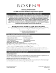
CARLO GAVAZZI
A u t o m a t i o n
C o m p o n e n t s
WM24-96
Universal Utility Meter
Contatore Universale
USER MANUAL
MANUALE ISTRUZIONI
Modular system
Tecnologia modulare
CARLO GAVAZZI
C o m p o n e n t s
ING
WM24-96: Modular Universal Utility
Meter and Power Analyzer
Plug and play module system; energy meters, gas and water meter.
These are only a few among many
other functions performed by your
WM24-96. What’s more, Carlo
Gavazzi means ISO9001 certification,
a working experience of many
decades and a widespread presence
all over the world. All this because
we want our customers to have the
top service and the top products.
A
Plu
TH
K
g
YO
U
FO
R
M and
od
P
ule lay
s
CH
OOS
Welcome in the Carlo Gavazzi world
and compliments for your smart
choice. Visit our website and
evaluate our range of products:
www.carlogavazzi.com
N
CARLO GAVAZZI
A u t o m a t i o n
2
Index
CARLO GAVAZZI
WM24-96, modular universal utility meter and power analyzer
FW rev. 01
TO BEGIN WITH . . . . . . . . . . . . . . . . . . . . . . . . . . . .
■ Front panel description . . . . . . . . . . . . . . . . . .
■ List and description of displayed measuring pages . .
PROGRAMMING . . . . . . . . . . . . . . . . . . . . . . . . . . .
■ Access to the main menu . . . . . . . . . . . . . . . . .
■ Change password . . . . . . . . . . . . . . . . . . . . . .
■ System . . . . . . . . . . . . . . . . . . . . . . . . . . . . . .
■ CT ratio . . . . . . . . . . . . . . . . . . . . . . . . . . . . . .
■ VT ratio . . . . . . . . . . . . . . . . . . . . . . . . . . . . . .
■ Dmd calculation . . . . . . . . . . . . . . . . . . . . . . .
■ Access to the energy meters menus . . . . . . . .
❑ The functions of the Energy Meters submenu.
■ Digital outputs . . . . . . . . . . . . . . . . . . . . . . . . .
❑ Digital output 1 . . . . . . . . . . . . . . . . . . . . .
❑ Pulse digital output . . . . . . . . . . . . . . . . . .
❑ Alarm digital output . . . . . . . . . . . . . . . . . .
❑ Digital output 2 . . . . . . . . . . . . . . . . . . . . .
■ Setting of serial communication port address . .
■ Digital filter . . . . . . . . . . . . . . . . . . . . . . . . . . . .
■ End of programming . . . . . . . . . . . . . . . . . . . .
■ Reset of total gas, water, energy meters . . . . .
■ Reset of partial gas, water, energy meters . . . .
■ How to prevent key-pad programming . . . . . . .
USEFUL INFORMATION . . . . . . . . . . . . . . . . . . . . . .
■ Example of how to use the digital filter . . . . . . .
■ What is ASY? . . . . . . . . . . . . . . . . . . . . . . . . . .
■ Retransmitted variables . . . . . . . . . . . . . . . . . .
■ Alarm digital output . . . . . . . . . . . . . . . . . . . . .
.
.
.
.
.
.
.
.
.
.
.
.
.
.
.
.
.
.
.
.
.
.
.
.
.
.
.
.
.04
.04
.04
.09
.09
.09
.10
.10
.11
.11
.13
.13
.16
.16
.16
.18
.19
.20
.20
.21
.21
.22
.22
.23
.23
.24
.24
.25
3
▲
▲
Front Panel Description
4
3
Index
INSTALLATION . . . . . . . . . . . . . . . . . . . . . . .
■ Operations preliminary to the installation
■ Front panel cut-out . . . . . . . . . . . . . . . .
■ Position of slots and relevant modules . .
■ Connection of optional modules . . . . . . .
■ 1-phase electrical diagrams . . . . . . . . . .
■ 3-phase electrical diagrams . . . . . . . . . .
TECHNICAL FEATURES . . . . . . . . . . . . . .
.
.
.
.
.
.
.
.
.
.
.
.
.
.
.
.
.
.
.
.
.
.
.
.
.
.
.
.
.
.
.
.
.
.
.
.
.
.
.
.
.
.
.
.
.
.
.
.
.26
.26
.27
.28
.31
.34
.34
.36
We suggest you to keep the original packing in case it is
necessary to return the instrument to our Technical
Service Department. In order to achieve the best results
with your instrument, we recommend you to read this
instruction manual carefully.
HOW TO USE THE SYMBOLS
Go to the page where the previous main subject
is described.
▲
Go to the page where the next main subject is
described.
▲
Go to the page where the subject written on the
top of the current page starts.
Go to the page where the subject written on the
top of the current page ends.
This symbol indicates a particularly important
subject or information.
This symbol indicates that more details are given
on the current subject.
2
▲
▲
Display “tot -1 .Cn”
7
4
To begin with
■ Front Panel Description
Back-lighted LCD Display.
Display previous page.
Display next page.
Access to programming or
setting confirmation.
■ List and Description of Displayed
Measuring Pages
When the instrument is switched on it shows the page below:
PF∑
kW∑
kvar∑
▲
Hz
▼
kW∑
PF∑
kVA∑
▲
▼
kW dmd
kVA dmd
▼
Serial communication status: r=Rx;
t=Tx (only with
serial communicat.
module inserted)
Gas, water, en. meters pages
8
▲
▲
▲
Hz
6
To begin with
VL2-N
VL1-N
VL3-N
▲
▼
A L2
V∑
If displayed in the
measuring mode it
means: the alarm is
ON.
An
A L1
A L3
▲
5
▼
W L2
W L1
W L3
▲
▲
Multiplyer
▼
PF L1
PF L2
PF L3
PF ∑
▼
kvar L2
kvar L1
kvar L3
▲
▼
kVA L2
kVA L1
kVA L3
▲
▼
Index
▲
Programming
4
8
▲
3
9
6
To begin with
The energy meter pages are different according to the setting of the instrument (see energy meter menu on pag.13).
■ If you choose “tot” the instrument displays:
Generated capacitive reactive
energy: integration of the sum of
single phase reactive powers of
quadrant 4 only.
▲
▼
Consumed capacitive reactive
energy: integration of the sum of
single phase reactive powers of
quadrant 2 only.
▲
▼
Generated inductive reactive
energy: integration of the sum of
single phase reactive powers of
quadrant 3 only.
▲
▼
Consumed inductive reactive
energy: integration of the sum of
single phase reactive powers of
quadrant 1 only.
▲
▼
Generated active energy: integration of the sum of single phase
negative active powers only.
▼
“tot-Prd”
4
8
▲
▲
▲
8
To begin with
7
Consumed active energy: integration of the sum of positive single phase active powers only.
▲
▼
■ If you choose “tot-1.Cn” the instrument displays all
the pages displayed in the “tot” selection as well as:
GAS meter as m3, night tariff.
▲
▼
GAS meter as m3, day tariff.
▲
▼
■ If you choose “tot-2.Cn” the instrument displays all
the pages displayed in the “tot” selection as well as:
Total WATER meter as m3.
▲
▼
Total GAS meter as m3.
▲
▼
dmd calculation
4
8
▲
5
▲
Measuring Pages
11
8
To begin with
■ If you choose “tot-Prd” the instrument displays:
Reactive energy consumed during tariff 1: integration of the system active power only if positive
(same is also for tariff 2, 3 and 4).
▲
▼
Active energy consumed during
tariff 1: integration of the system
active power only if positive
(same is for tariff 2, 3 and 4).
▲
▼
Consumed total reactive energy:
integration of the system reactive
power only if positive.
▲
▼
Consumed total active energy:
integration of the system active
power only if positive.
▲
▼
Once the energy meter pages are finished, the instrument
will display some pages related to the variables connected
to the alarm.
Display of alarm settings (AL1 and
AL2 if both alarms have been set).
It displays the variable connected
to the alarm.
▲
▼
The scrolling of the measuring pages is cyclic, at the end of the
cycle, you go back to the first page (see page 4).
Index
▲
System
4
▲
3
10
Programming
9
■ Access to the main menu
To access to the programming
menus from the measuring and display phase, press the S key : when
the instrument asks for the password, enter the correct PASS value
S
by means of the ▲ and ▼ keys;
afterwards confirm by means of the
S
▲
▼
Access to the
main menu
S key. If the password is correct
(when the instrument is new, the
password is 0), the instrument goes
to the main functions menu.
When the “AL” box (normally used for the alarm
indication) is active during the programming phase,
it means that the displayed value can be modified.
This rule applies to all the programming menus.
■ Change Password
This function allows the operator to
choose the desired password value
(from 0 to 1000).
Choose the “CnG.PASS” function
S
by means of the ▲ and ▼ keys,
then press S to modify PASS,
enter the desired value by means of
the ▲ and ▼ keys and confirm
▲
S
▼
the new value with the S
En. meters Menu
22
▲
▲
En. meters Display
7
key.
13
10
Programming
■ System
This function allows the operator to
select the electrical system choosing between three-phase with neutral (3P.n) and three-phase without
neutral (3P).
S
Choose by means of ▲ and ▼
the “SySTEn” function, press S
to enter the menu; then, select the
desired system by means of the
▲ and ▼ keys and confirm with
S .
▲ ▼
S
■ CT ratio
S
▲
S
1.2..
..2.1
▼
This function allows the user to
select the value of the CT ratio.
Example: if the CT primary (current
transformer) has a current of 300A
and the secondary has a current of
5A, the CT ratio corresponds to 60
(obtained by carrying out the following calculation: 300/5).
Choose the “Ct.rAtio” function by
means of the ▲ and ▼ keys; to
enter the menu press S ; then
select the desired value by means
S
of the ▲ and ▼ keys and confirm the new value with S .
▲ ▼
S
Synchronization
9
22
▲
5
▲
Measuring Pages
12
Programming
11
■ VT ratio
S
▲
S
1.2..
..2.1
▼
This function allows the user to
select the value of the VT ratio.
Example: if the primary of the connected VT (voltage transformer) is
of 20kV and the secondary is 100V,
the VT ratio will correspond to 200
(obtained by carrying out the following calculation: 20000/100).
Choose the “Vt.rAtio” function by
means of the ▲ and ▼ keys; to
enter the menu press S , then
select the desired value by means
S
of the ▲ and ▼ keys and con-
▲ ▼
S
firm it with S .
By changing the VT and
CT ratio, the energy
meters are reset.
■ Dmd calculation
This function allows the user to
select the integration time of the W
and VA demand value. To enter
these functions select “P.int t” from
S
the main menu by the ▲ and ▼
keys; to enter the menu press S .
Set the minutes by means of the
▲ and ▼ keys and confirm the
S
▲
1.2..
..2.1
▼
new value with S .
Main Menu
▲
Digital Input Table
9
22
▲
9
15
12
Programming
If, for example, you select the value “15 minutes”, the instrument calculates the demand value
and updates the value every 15 minutes. See the
diagram below.
Where:
Pc is the contractual power
t1 is the selected integration period
SYNCHRONIZATION OF THE POWER DEMAND CALCULATION
The synchronization enables the WM24-96, by means of the
digital inputs, to start the integration of the power demand
at the same time as the official watthour meter. The synchronization can be carried out in two ways:
- Without digital input module: the reset and the start of the
energy integration are carried out when the instrument is
switched on;
- With the digital input module: the synch. starts when one
of the digital inputs changes status (that is to say when the
tariff changes). Any following change of status resets and
synchronizes again the calculation of the power demand.
Meters Submenu
9
22
▲
▲
Energy Meters Pages
7
14
Programming
13
■
Access to the energy
meters menu
This function allows the user to choose
the parameters for the management of
the energy meters. Choose the function
S
“COUntEr” by means of the ▲ and
▼ keys: to confirm the value and enter
the submenu press S . By means of
S
▲
▼
the ▲ and ▼ keys, it’s possible to
scroll all the functions relating to the
energy meters that will be described in
detail below.
❑
The functions of the Energy
Meters submenu.
Choose the desired function by
S
▼
means of the ▲ and ▼ keys,
▼
press S to confirm. It’s possible
to choose the following combinations:
tot: it enables the combination of
total and partial meters (see page
6).
tot Prd: it enables the combination
of total and partial meters: tariff t1,
t2, t3 and t4 are managed by the
digital inputs (see page 8);
▲
S
▲
VT Ratio
▲
Retransmitt. en. Meters
9
22
▲
11
17
14
Programming
tot 1.Cn: it enables the combination of
total en. meters and day-time and nighttime GAS meters (see also “Display
pages” on page 7). Press S to select
“PrESCAL Cn1”, then enter by means
S
of the ▲ ▼ keys the weight of every
pulse of the IN2 digital input of the GAS
S
▲
1.2..
..2.1
▼
meters and confirm with S .
The same input IN2 increases alternatively the day-time and night-time GAS
meters depending on the status of IN3.
tot 2.Cn: it enables the combination of
total energy meters and Water and Gas
meters (see also “Display pages” on
page 7). Press S to select “PrESCAL
S
▲
Cn1” then enter by means of the
▼ keys the weight of every pulse of
the IN3 digital input of the water meters,
▲
S
1.2..
..2.1
▼
confirm with S and go to the
“PrESCAL Cn2” submenu.
Enter by means of the ▲ ▼ keys
the weight of every pulse of the IN2
digital input of the Gas meter, then
confirm with S .
▲
S
1.2..
..2.1
▼
The prescaler (PrESCAL) sets the weight of the input
pulses of the digital input module; e.g.: by setting the
prescaler at 10, for each received pulse the meter
increases by 10 (10, 20, 30, etc.). The range of the
prescaler varies from 0.1 to 100.0.
Main Menu
▲
Digital Outputs
9
22
▲
9
16
Programming
15
The increase of the Water, Gas meters, the selection of night/day tariff of the gas meters or the
change of tariff (t1, t2 t3, t4) is carried out thanks to
the combination of the input pulses to the AQ1038
or AQ1042 digital input module, according to the
following table:
SETTING
RESULT
DIGITAL INPUTS
OF
INSTRUMENT
Setting “tot Prd”
Display of total and partial multi-tariff energy
meters.
Setting “tot 1.Cn”
Display of total en.
meters
and
GAS
day/night tariff.
Setting “tot 2.Cn”
Display of total energy
meters, GAS and
WATER.
IN 3
IN 2
ON
ON
Tariff 1
OFF
ON
Tariff 2
ON
OFF
Tariff 3
OFF
ON
Tariff 4
Increase GAS night tariff
of
GAS
meters GAS day tariff
(*)
ON
OFF
Increase Increase
of
of
WATER
GAS
meters meters
(*)
(*)
(*) The pulse corresponds to an increase of the various
meters by the pre-set weight.
If the IN 1 contact is closed (3 digital inputs module), the
programming from key pad is inhibited.
The synchronisation starts at the status modification of the
digital inputs (IN2 and IN3) when the instrument is set to
“tot” or “tot-Prd”.
Digital Output 2
9
22
▲
▲
Energy Meters
13
19
16
Programming
■ Digital Outputs
❑ Digital Output 1
This function enables to set the
parameters of the digital outputs.
Choose the “diGout” function by
S
means of the ▲ and ▼ keys, to
S
enter the menu press S . Then,
select one of the following
options;
PUL: access to the retransmission
functions of the totalized energy
by means of pulses (see pulse digital output);
ALr: access to alarm functions
(see alarm digital output); To enter
S
S
▲ ▼
Alarm digital output on page 18
to relevant menu press S ;
rEn: enables the activation of the
output by means of the serial
communication. Confirm with S
to enable the function.
Digital output 2
on page 19
❑ Pulse digital output
Select “diGout1 PUL” by means of
S
the ▲ and ▼ keys: press S
to enter the relevant programming
submenu, then choose the meter
to be retransmitted among the
available ones.
▲ ▼
S
Alarm Output
9
22
▲
▲
dmd Calculation
11
18
Programming
17
The list displaying the en. meters to be retransmitted
varies depending on the chosen setting of the
instrument, that is, depending on the “en. meter”
selection chosen among: “tot”, “tot-Prd”, “tot1.Cn”, “tot-2.Cn”, as reported in the table below:
IF
IF
THE SELECTION IS
THE SELECTION IS
tot, tot-1.Cn, tot-2.Cn:
tot-Prd:
kWh (consumed)
kWh- (generated)
kvarh ind (cons. inductive)
kvarh -ind (gen. inductive)
kvarh CAP (cons. capacitive)
kvarh -CAP (gen. capacitive)
kWh tot (total energy meter)
kvarh tot (total en. meter)
kWh t1 (energy meter tariff 1)
kvarh t1 (energy meter tariff 1)
and so on for the other
tariffs t2-t3-t4.
EXAMPLE
OF
DISPLAY
Scroll the energy meters displayed by means of ▲
▼ and
choose the desired one by means of S , then the instrument displays the page where the pulses to be associated
to the energy are indicated.
Select the number of pulses by
means of ▲
▲
S
1.2..
..2.1
▼
▼ (pulses/kWh from
1 to 100) and confirm with S . The
programming continues for digital
output 2.
Digital output 2
on page 19
End of Programming
9
22
▲
▲
Digital Input Table
15
21
18
Programming
❑ Alarm Digital Output
This function allows the
user to set the parameters of the
alarm digital output. Choose the
“diGout1- ALr” function by means
S
of the ▲
▲ ▼
S
▼ keys: to enter the
menu press S . Then, set the following parameters:
VAr: choose the variable to be
associated to the alarm activation
by means of the ▲ and ▼ keys
▲
S
▼
and confirm with S .
rnG: choose the decimal point
position.
on: activation set-point, value of the
variable over which the alarm is activated. Select the value of the variable
by means of the ▲ and ▼ keys
S
▲
1.2..
..2.1
S
▲
1.2..
..2.1
▼
▼
and confirm it with S ;
oFF: deactivation set-point, value of
the variable over which the alarm is
deactivated. Select the value of the
variable by means of the ▲ and
▼ keys and confirm it with S ;
nd: normally de-energized output
when there is no alarm.
nE: normally energized output
when there is no alarm.
Select the output status by means
of the ▲ and ▼ keys and confirm it with S ;
Digital Filter
9
22
▲
▲
Energy Meters Menu
13
20
Programming
19
SEC: delay time from the detection
of the alarm and the activation of
the output. Choose the value of the
delay time in seconds by means of
▲
S
1.2..
..2.1
▼
the ▲ and ▼ keys (up to 255
seconds) and confirm with S .
Digital output 2
❑ Digital Output 2
PUL: access to the retransmission
functions of the totalized energy by
means of pulses (see pulse digital
output on page 16).
ALr: access to alarm functions (see
alarm output on page 18). To enter
S
the relevant menu press S ;
rEn: enables the activation of the
output by means of the serial communication. Confirm with
enable the function.
S
to
▲ ▼
S
9
Useful Information
22
▲
▲
Retransmittable en. meters
17
23
20
Programming
■ RS422/485 Serial port
address
Select “AddrESS” from the main
menu by means of the ▲ and ▼
S
keys; to enter the menu press S ,
then set the desired serial address
value (from 1 to 255) by means of
the ▲ and ▼ keys and confirm it
▲
S
1.2..
..2.1
▼
with S .
■ Digital Filter
Select “FiLtEr” by means of the ▲
and ▼ keys: to enter the menu press
S
S . Select the parameters to be set
with the ▲ and ▼ keys, to enter
▲
S
1.2..
..2.1
▼
the menu press S .
There are two parameters:
- rnG, sets the operating range of the
digital filter. The value is expressed as
% of the full scale value: set the
desired value (from 0 to 100%) by
means of the ▲ and ▼ keys and
▲
S
1.2..
..2.1
▼
confirm it with S ;
- Coe, sets the filtering coefficient of the instantaneous measurements. Set the desired value (from 1 to 16) by means of the ▲ and
▼ keys and confirm it with S . By increasing the value both the
stability and the settling time of the measurements are increased.
See also “Example 2” in Useful Information on page 23.
Meters Reset
9
22
▲
▲
Meters Increase
15
22
Programming
21
■ End of programming
To exit from programming and go
back to the measuring mode, select
“End” from the main menu by means
S
of the ▼ and ▲ keys, confirm it
Measuring Instrument
mode
revision
with S .
■ Reset of total meters
Select “rESEt tot” from main
menu by means of the ▲
S
S
▼ keys,
S . When the
then confirm with
instrument asks for the reset, choose,
by means of the ▲ ▼ keys:
“no” to avoid the reset or
“yes” to confirm it.
Then, press S to carry out the command.
▲ ▼
S
RESET
Up/Down Alarm
9
22
▲
▲
Digital Output 2
19
25
22
Programming
■ Reset of partial meters
Select “rESEt Prt” from the main
menu by means of the ▲
S
▼ keys,
then confirm with S . When the
instrument asks for the reset, choose,
by means of the ▲ ▼ keys:
“no” to avoid the reset or
“yes” to confirm it.
Then, press S to carry out the command.
▲
S
RESET
■ How to prevent the programming by key-pad
It is possible to prevent any access to
programming by modifying the switch in
the power supply slot (see the drawing on
the left), or closing the contact N 1 of the
digital input module if present.
Turn the switch using a little screwdriver.
- Free programming.
- Lock programming.
10
What is ASY
▲
▲
Retransmittable meters
17
24
Useful Information
23
The variables measured by the instrument are
correct if the polarities of the inputs have been
observed (as shown in the figure below); if not,
measuring and retransmission errors may occur due to
the wrong direction of the current flowing in the primary
/ secondary of the connected current transformer.
Example 2 “Use of digital filter”: it’s necessary to stabilize
the displayed value of the VL1-N variable that varies between
222V and 228V. The parameters of the digital filter are to be
set as follows:
• rnG: the variable varies within the average value, the
amplitude of which is equal to ±1.3% of the variable’s rated
value, calculated as follows:
(228-222)/2=±3V, then ±3*100/231V=±1.3%, where 231V
is the phase-neutral rated value of a 400V input range. The
“range” parameter, that corresponds to the action range of
the digital filter, is set at a value which is slightly higher than
the percentage amplitude of the fluctuation: e.g. 2%.
• CoE: if the new value acquired by the instrument is within the filter’s action range, then the new displayed value is calculated by summing algebraically to the previous value the
variation divided by the filtering coefficient. As a consequence, a value which is higher than this coefficient implies a
longer settling time and therefore improves the stability. The
latter can also be improved by increasing the filtering coefficient: the admitted values are within 1 and 16. Enter the value
in consecutive attempts until you reach the desired stability.
Dimensions
25
▲
▲
End of Programming
21
27
24
Useful Information
■ What is ASY
The ASY variable allows the user to control the symmetry of
the delta voltages (for systems without neutral) and star voltages (for systems with neutral). The variable is calculated
according to the following formula:
ASY=
Where:
Vmax - Vmin
Vavg
*100
Vmax is the max. value among VL1-N, VL2-N, VL3-N
Vmin is the min. value among VL1-N, VL2-N, VL3-N
Vavg is the average: (VL1-N, VL2-N, VL3-N)/3
The variable is not displayed by the instrument, but can be
retransmitted by the analogue or RS422 / 485 output and
can be controlled by means of the alarm.
■ Retransmitted variables
N°
Variable
3-ph with 3-ph withNotes
neutral
out neutral
V L-NΣ
x
Σ = system
V L-LΣ
x
x
Σ = system
WΣ
x
x
Σ = system
varΣ
x
x
Σ = system
VAΣ
x
x
Σ = system
PFΣ
x
x
Σ = system
PF
x
x
VA dmd
x
x
W dmd
x
x
ASY
x
x
asymmetry
The energy meters as per table on page 17
All instantaneous variables (powers, currents, voltages)
1
2
3
4
5
6
7
8
9
10
11
12
Installation
23
25
▲
▲
Digital Output 2
19
26
Useful Information
25
■ Alarm digital output
The activation of the alarm can be up or down depending on
how the ON and OFF parameters have been set, as per the
following table:
ON-OFF
VALUES STATUS
ALARM TYPE
ON ≥ OFF
UP
ON < OFF
DOWN
■ Displaying of programming menu
It may be useful to know that the menus displayed
by the instrument depend on its configuration;
e.g.: the instrument will not display the menu relevant to the digital outputs if the optional module
is not inserted.
It is important that the instrument is switched
off when you plug-in or disconnect the modules.
23
Available Modules
▲
▲
E.g.: Use of Digital Filter
23
29
26
Installation
■ Preliminary operations
Before switching the instrument on, make sure that the
power supply voltage corresponds to what is shown on the
side label of the relevant module.
■ Before mounting the modules
To know in which slot every module is to be mounted,
refer to the figure on page 28. For a correct mounting of the
instrument, insert the modules in the relevant slots, then, at
the end, enter the central module, which can be a blind type
module or an RS232 communication module. The central
module will help fixing also the other modules in the relevant
slots. To remove the modules use a screwdriver as shown in
the picture below.
1
Gently depress the
two fixing tabs.
Directions 1-4.
2
Remove the central module
from its slot: press your
thumb towards points 2-5.
Extract the
central
module.
3
Any other slots that are not
used must be filled with the relevant blind plug modules supplied with the instrument.
Position of Slot
35
▲
▲
End of Programming
21
28
27
Installation
■ Overall dimensions and panel cut-out
❑ Mounting
Insert the instrument (holding
its front) and fasten it (from the
back) by fixing the two lateral
brackets (1) (supplied with the
instrument) to the appropriate
location (2), using the two
screws (3) supplied with the
instrument.
2
1
3
Optional Modules conn.
26
35
▲
▲
Up/Down Alarm
25
31
28
Installation
■ Position of the slots and relevant modules
B
A
D
C
PU
IM
PS
■ Available modules
❑ Relay digital output modules
AO1035
Dual relay
output
AO1058
Single relay
output
26
Optional Modules
35
▲
▲
E.g.: Use of Digital Filter
23
30
29
Installation
DESCRIPTION
A
B
C
D PU PS IM
✓
RS485/RS422 serial port
✓
RS232 serial port
Single relay output
✓
✓
Single open collector output
✓
✓
Dual relay output
✓
✓
Dual open coll. output
✓
✓
3 digital inputs
✓
3 digital inputs +AUX
✓
✓
Power supply
✓
Measuring inputs
❑ Open collector digital output modules
AO1059
Single open
collector output
AO1036
Dual open
collector output
Mounting
▲
Serial connection
26
35
▲
27
33
30
Installation
❑ Digital input modules
AQ1038
3 digital
inputs
AQ1042
3 digital inputs +
aux
❑ Serial port modules
AR1039
RS232 serial port
AR1034
RS485/422
serial port
❑
Power supply modules
AP1025
24VAC Power supply
AP1024
48VAC Power supply
AP1023
115VAC Power supply
AP1022
AP1020
90-260 VAC/DC Power supply 230VAC Power supply
AP1021
18-60VAC/DC Power supply
Relay Output conn.
26
35
▲
▲
Up/down Alarm
25
32
Installation
31
■ Optional module connections
❑ Digital inputs
Connection by
NPN transistor.
AQ1042
Digital input
module.
Connection by
PNP transistor.
AQ1042
Digital input
module.
Connection by
contacts.
AQ1042
Digital input
module.
Connection by
contacts.
AQ1038
Digital input
module.
3-ph 3-wire connection
26
35
▲
▲
Modules Position
29
35
32
Installation
❑ Relay output
AO1058
Single relay output
AO1035
Dual relay output
❑ Open collector output
This diagram is valid also
for the single output open
collector module.
The value of the load
resistances (Rc) must be
chosen so that the shortcircuit current is lower
than 100mA; the VDC
voltage must be lower
than or equal to 30 VDC.
AO1059
Single open collector output
AO1036
Dual open collector output
Dimensions
▲
Electrical diagrams
26
35
▲
27
34
Installation
33
❑ RS485/422 (AR1034) serial port
4-wire connection. Additional devices provided with
RS485/RS422 (that is RS 1,2,3...N) are connected in parallel.
2-wire connection. Additional devices provided with
RS485/RS422 (that is RS 1, 2, 3 ...N) are connected in parallel.
The termination of the serial output is carried out
only on the last instrument of the network, by
means of a jumper between (Rx+) and (T).
We recommend you to use the 4-wire connection:
by means of the serial port the data are exchanged
faster.
Technical features
26
35
▲
▲
Digital Input Conn.
31
37
34
Installation
■ Electrical diagrams
❑ Single-phase connection
I
1
3
5
L1
L2
L3
2
4
6
8
L1
7
N
10
L3
L2
9
U
I
CT connection
1
3
5
L1
L2
L3
2
4
6
8
L1
7
N
10
L3
L2
9
U
L1
L1
N
N
CT and VT connections
❑ Three-phase, 4-wire, unbalanced load
CT connection
(4-wire system)
CT and VT connections
(4-wire system)
Accuracy
26
35
▲
▲
Available Modules
29
36
Installation
CT and VT connections
(3-wire system)
35
3 CT and 3 VT connections
(3-wire system)
❑ ARON connection, 3-phase, 3-wire, unbalanced load
CT connection
(3-wire system) ARON
CT and VT connections
(3-wire system) ARON
Technical Features
26
▲
▲
Serial Connection
33
39
36
Technical Features
■ Number of inputs
Current: 3; Voltage: 4
■ Accuracy (display, RS232, RS485) In=5A; Pn= In* Un
Current: 0.003Ib to 0.2Ib: ±(0.5% rdg + 3DGT);
0.2Ib to Imax: ±(0.5 rdg + 1DGT);
Phase-neutral voltage: Un range: ±(0.5% rdg + 1DGT)
Frequency: ±0.1% Hz
Active power/energy: class 1 according to EN61036
Reactive power/energy: class 2 according to EN61268
Apparent power/energy: ±(1% Pn+2dgt), (@25°C ±5°C, R.H. ≤60%)
■ Temperature drift
≤ 200ppm/°C
■ Display refresh time
700ms
■ Display
Back-lighted LCD 70 x 38mm
1
4x3 /2 dgt: instantaneous variables;
1
1x7 /2 dgt: energy meters.
■ Measurements
Current, voltage, power, power factor, frequency, energies.
TRMS measurements of distorted waves.
Coupling type: direct.
■ Input impedance
208VLL
400VLL
100VLL
660VLL
5(6)AAC
5(6)AAC
5(6)AAC
5(6)AAC
(AV4):
(AV5):
(AV6):
(AV7):
>200
>900
>200
>900
kΩ
kΩ
kΩ
kΩ
(phase-neutral)
(phase-neutral)
(phase-neutral)
(phase-neutral)
■ Input/Output modules technical features
RS422/RS485 (on request)
Multidrop bidirectional (static and dynamic variables)
Digital Inputs
40
▲
▲
Digital Inputs Connection
31
38
Technical Features
37
Connections: 2 or 4 wires, max. distance 1200m, termination directly on the instruments.
Addresses: from 1 to 255, selectable by key-pad
Protocol: MODBUS/JBUS (RTU)
Data (bidirectional) Dynamic (reading only)
System and phase variables: see “display pages” on page 41
All configuration parameters, activation of the static output.
Data format: 1 start bit, 8-data bit, no parity,1 stop bit.
Baud-rate: 9600.
Insulation: By means of optocouplers, 4000 VRMS between
output and measuring input, 4000 VRMS between output and
power supply input.
RS232 (optional)
Bidirectional (static and dynamic variables)
Connections: 3 wires, max. distance: 15m.
Data format: 1 start bit, 8 data bit, no parity, 1 stop bit.
Baud-rate: 9600 bauds. Protocol: MODBUS (JBUS)
Other features: as per RS422/485
Pulse outputs (optional)
Number of outputs: Up to 2
Type: from 1 to 100 programmable pulses VON 1.2 VDC/ max.
100 mA. VOFF 30 VDC max.
The outputs can be connected to total and/or partial en. meters.
Pulse duration: ON=220 ms, OFF≥ 220 ms according to
DIN43864
Insulation: By means of opto-couplers, 4000 VRMS between
output and measuring input, 4000 VRMS between output and
power supply input.
Notes: outputs can be open collector or relay type (for the
relay output refer to the technical features described in the
alarms).
36
40
▲
▲
Electrical diagrams
35
38
Technical Features
Alarm outputs (optional)
Number of outputs: up to 2, independent
Alarm type: up or down alarm, phase asymmetry
Control on the variables: All variables listed in the paragraph
“retransmitted variables” on page 24 can be controlled.
Alarm set-point: can be modified from 0 to 100% of the displayed electrical scale.
Hysteresis: From 0 to 100% of the displayed scale
On-time delay: from 0 to 255 sec
Relay status: selectable, normally disabled or normally
enabled.
Output type: Relay, SPDT AC 1-8A, 250VAC; DC 12-5A,
24VDC; AC 15-2.5A, 250VAC; DC 13-2.5A, 24VDC
Min. response time: ≤ 150 ms, filters excluded, FFT excluded, on-time delay: ”0”
Insulation: 4000 VRMS between output and measuring input,
4000 VRMS between output and power supply input.
Notes: Outputs can be open collector type or relay type (for
the open collector type refer to the technical features
described in the pulse outputs).
Digital inputs
AQ 1038: N. of inputs: 3 (free-of-voltage)
Reading voltage: 24VDC/1mA
AQ1042: N. of inputs: 3 + power supply inputs
Power supply inputs:
output voltage: 16V<+Aux<24VDC;
output current: Max 15mA.
Input frequency: Max 20Hz, duty cycle 50%
Close contact resistance: Max 1kΩ
Open contact resistance: Min 100kΩ
Insulation: 4000VRMS
Use of contact 1: lock of the programming from key-pad
(when the contact is closed).
General Specifications
36
40
▲
▲
Electrical diagrams
33
40
Technical Features
39
Contacts 2-3: to be used in one of the following ways:
• tariff selection (t1-t2-t3-t4) and synchronization;
• total meters for day-night GAS tariffs;
• total GAS and WATER meters ;
■ Software functions
Password: Numerical code of 4 dgts; 2 protection levels of
the programming data
1st level: Password “0”, no protection
2nd level: Password from 1 to 1000, all data are protected
Transformer ratio: CT from 1 to 5000
VT from 1.0 to 1999, with CT x VT ≤10000 max
Power dmd: Integration time programmable from 1 to 30 min
Filter: operating range: from 0 to 100% of the electrical input
scale
Filtering coefficient: 1 to 16
Filtering action: measurements, alarms, serial output
Display: up to 4 variables per page, 3-phase system with
neutral:
Page 1: V L1, V L2, V L3, V LN∑
Page 2: AL1, AL2, AL2
Page 3: W L1, W L2, W L3
Page 4: VA L1, VA L2, VA L3
Page 5: var L1, var L2, var L3
Page 6: PF L1, PF L2, PF L3, PF ∑
Page 7: W ∑, var ∑, PF ∑, Hz
Page 8: W ∑, VA ∑, PF ∑, Hz
Page 9: W dmd, VA dmd
Counter pages depending on the instruments setting:
Wh+ tot, Wh- tot, Wh tot, varh tot, varh L+ tot, varh L-,
varh C+, varh C-, m3 day GAS, m3 night GAS,
m3 GAS, m3 WATER, Wh t1, Wh t2, Wht 3, Wht4, varht1,
varht2, varht3, varht4.
36
40
▲
▲
Pulse outputs
37
40
Technical features
■ Power supply specifications
90 to 260 VDC/VAC;18 to 60VDC/VAC;
24 VAC -15%+10% 50-60Hz; 48 VAC -15%+10% 50-60Hz;
115VAC -15%+10% 50-60Hz; 230 VAC -15%+10% 50-60Hz
■ General features
Operating temperature:
0 to +50°C (32 to 122°F) (H.R. < 90% non condensing)
Storage temperature:
-10 to +60°C (14 to 140°F) (HR. < 90% non-condensing)
Installation category: Cat. III (IEC 664)
Key-pad lock: by means of switch placed behind the display or by means of contact (if module 3 - input contacts is present).
Insulation: 4000 VRMS between inputs/outputs and ground
Dielectric strength: 4000 VRMS for 1 minute
■ EMC
Emissions: EN50082-1 (class A) residential, commercial
and light industry environment. Immunity: EN 61000-6-2
(class A) industrial environment.
■ Other standards
Safety: IEC 61010-1, EN 61010-1
Product: IEC 60688-1, EN 60688-1
Approvals: CE
5(6)A connections: screw-type, max. section 2.5 mm2
(2 x 1.5mm2)
Housing: Dimensions: 96x96x140 mm
Material: ABS, NORYL, PC (front); self-extinguishing: UL 94 V-0
Protection degree: Front: IP65
Connections: IP20
Weight: approx. 400 g (packing included)
36
▲
▲
Electrical diagrams
35
Carlo Gavazzi GmbH
Wien - AUSTRIA
Carlo Gavazzi Automation Sdn Bhd
Petaling Jaya, Selangor - MALAYSIA
Carlo Gavazzi NV/SA
Vilvoorde - BELGIUM
Carlo Gavazzi BV
Beverwijk - NETHERLANDS
Carlo Gavazzi Inc.
Mississauga, ON - CANADA
Montreal, PQ - CANADA
Carlo Gavazzi AS
Porsgrunn - NORWAY
Carlo Gavazzi Handel A/S
Hadsten - DENMARK
Carlo Gavazzi OY AB
Helsinki - FINLAND
Carlo Gavazzi Lda
Lisboa - PORTUGAL
Carlo Gavazzi SA
Leioa (Bizkaia) - SPAIN
Carlo Gavazzi Sarl
Roissy - FRANCE
Carlo Gavazzi AB
Karlstad - SWEDEN
Carlo Gavazzi GmbH
Weiterstadt - GERMANY
Carlo Gavazzi AG
Steinhausen - SWITZERLAND
Carlo Gavazzi UK Ltd
Aldershot - GREAT BRITAIN
Carlo Gavazzi Inc.
Buffalo Grove IL - USA
Carlo Gavazzi SpA
Lainate (MI) - ITALY
WM24 ita-eng code 8020593 02/2003
OUR SALES NETWORK
OUR PRODUCTION SITES
Carlo Gavazzi Industri A/S
Hadsten - DENMARK
Carlo Gavazzi Ltd
Zejtun - MALTA
Carlo Gavazzi Controls SpA
Belluno - ITALY
SAIET Elettronica SpA
Castel Maggiore (BO) - ITALY
Inductive and Capacitive
Proximity
Sensors in full metal and
plastic
housings. Photoelectric
Sensors.
Level Sensors: Optical,
Conductive
and Capacitive.
Ultrasonic Sensors and
Magnetic
Switches. Limit Switches.
Solid States Relays.
Versions for PCB and panel
mounting.
AC Semiconductor Motor
Controllers
Soft starters.
Industrial and PCB Relays.
Energy Management.
Timers and Monitoring
Relays.
Digital Panel Meters and
Temperature Controllers.
Safety and Magnetic
Switches,
Safety Modules.
Mat Systems, Light Curtains,
Electrical Transient,
Protections.
Measuring Systems and
Encoders.
Further information on
Dupline Field and Installation
Bus.
Building Automation Systems.
CARLO GAVAZZI
A u t o m a t i o n
C o m p o n e n t s
www.carlogavazzi.com