1
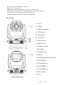
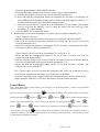
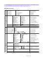
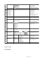
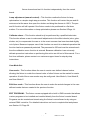
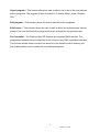
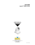
PLATINUM SPOT 15R PRO KEEP THIS MANUAL FOR FUTURE NEEDS Thank you for your patronage. We are confident that our excellent products and service can satisfy you. For your own safety, please read this user manual carefully before installing the device. In order to install , operate, and maintain the lighting safety and correctly. We suggest that the installation and operation should be done by the verified technician and follow the instruction strictly. Every person involved with the installation, operation and maintenance of this device has to: -be qualified -follow carefully the instructions of this manual INTRODUCTION: Thank you for having chosen this professional moving head. You will see you have acquired a powerful and versatile device. Unpack the device. Inside the box you should find: 1. One XLR connection cable 2. Two omega clamps 3. One safety rope 4. Manual Please check carefully that there is no damage caused by transportation. Should there be any, consult your dealer and don’t install this device. Features ·Lamp: Philips PLATINUM 15R ·3 DMX Channels mode: 21/23/34 channels ·Stand alone operation with Master/Slave function, sound activated via built in microphone. ·Pan and tilt movement: 8 and 16 bit resolution For smooth and precise motion Movement: Pan: 360°/540°optional, Tilt: 270° Speed of pan/tilt movement adjustable Scan position memory, auto reposition after unexpected movement ·Colors: Basic color wheel with 10 dichroic mirrors, plus white, two direction rainbow effect. ·CMY Variable Color Mixing for Infinite Color Possibilities ·Rotating gobo: 8 rotating gobos plus open, all gobos can be easily replaceable and gobo indexing ·Static gobo wheel with 14 indexing gobos plus open, gobo shaking in different speed ·Prism and prism rotating , with 16 prism macros ·Linear dimmer in precise speed from 0% ~ 100% ·Stepless frost, 0%~100% linear change frost ·Motorized focus - - 2 XM542-V1.0-NR ·Iris from 5%~100% with pulse iris effect. ·Zoom: 9°~27° linear zoom ·Strobe/shutter: High speed shutter, 0-13 Hz or random strobe ·Control board with full color LCD graphic display and touch-keyboard ·Auto-program: 7 pre-built programs can be selected. ·Software-upload by optional accessory via DMX line Overview 1) Lens 2) Display 3) Wireless indicator 4) DC Switch 5) Microphone 6) Left-button 7) Down-button 8) Right-button 9) Mode/Esc-button 10)Up-button 11)ENTER-button 12)Handle 13)Lamp bracketrear metal panel 14)3-Pin DMX in 15)3-Pin DMX out 16)5-Pin DMX in 17)5-Pin DMX out 18)Power input 19) Fuse - - 3 XM542-V1.0-NR SAFETY INSTRUCTIONS This device has left the factory in perfect condition. In order to maintain this condition and to ensure a safe operation, it is absolutely necessary for the user to follow the safety instructions and warning notes written in this user manual. Important: Damages caused by the disregard of this user manual are not subject to warranty. The dealer will not accept liability for any resulting defects or problems. If the device has been exposed to temperature changes due to environmental changes, do not switch it on immediately. The arising condensation could damage the device. Leave the device switched off until it has reached room temperature. This device falls under protection-class I. Therefore it is essential that the device be earthed. The electric connection must carry out by qualified person. Make sure that the available voltage is not higher than stated at the end of this manual. Make sure the power cord is never crimped or damaged by sharp edges. If this would be the case, replacement of the cable must be done by an authorized dealer. Always disconnect from the mains, when the device is not in use or before cleaning it. Only handle the power cord by the plug. Never pull out the plug by tugging the power cord. During initial start-up some smoke or smell may arise. This is a normal process and does not necessarily mean that the device is defective, it should decrease gradually. Please don't project the beam onto combustible substances. If the external flexible cable or cord of this luminaire is damaged, it shall be exclusively replaced by the manufacturer or his service agent or a similar qualified person in order to avoid a hazard. - - 4 XM542-V1.0-NR Please be aware that damages caused by manual modifications to the device are not subject to warranty. Keep away from children and non-professionals. GENERAL GUIDELINES This device is a lighting effect for professional use on stages, in discotheques, theatres, etc., the device was designed for indoor use only. This fixture is only allowed to be operated with the max alternating current which stated in the technical specifications in the last page of this manual. Lighting effects are not designed for permanent operation. Consistent operation breaks may ensure that the device will serve you for a long time without defects. Do not shake the device.Avoid brute force when installing or operating the device. While choosing the installation-spot, please make sure that the device is not exposed to extreme heat, moisture or dust. Please don't project the beam onto combustible substances.The minimum distance between light-output from the projector and the illuminated surface must be more than 1.5 meter. If you use the quick lock cam in hanging up the fixture, please make sure the quick lock fasteners turned in the quick lock holes correctly. Operate the device only after having familiarized with its functions. Do not permit operation by persons not qualified for operating the device. Most damages are the result of unprofessional operation. Please use the original packaging if the device is to be transported. For safety reasons, please be aware that all modifications on the device are forbidden. If this device will be operated in any way different to the one described in this manual, the product may suffer damages and the guarantee becomes void. Furthermore, any other operation may lead to short-circuit, burns, electric shock, lamp explosion, crash, etc. INSTALLATION INSTRUCTIONS a) Installing or replacing the lamp Before replacing the lamp let the lamp cool down, because during operation, the lamp can - - 5 XM542-V1.0-NR reach very high temperature. During the installation of halogen lamps do not touch the glass bulbs bare handed. Always use a cloth to handle the lamps during insertion and removal. Do not install lamps with a higher wattage. They generate higher temperatures than which the device was designed for. For the installation, you need one: PLATINUM 15R Procedures: 1) Unscrew the 3 screws (A, B, C) on the bottom of the housing, holding the plate where the lamp is underneath. Carefully remove the metal plate. 2) For lamp replacement please move the lamp along arrowhead for the silkscreening . Please remember the lamp is not a hot-restrike type, you must wait for approximately 10 minutes after having turned off the lamp before you can turn it back on again. b) Mounting the device The applicable temperature for the lighting is between -25°C to 45°C. Do not use the lighting under or above the temperature. The installation of the effect has to be built and constructed in a way that it can hold 10 times the weight for 1 hour without any harming deformation. The installation must always be secured with a secondary safety attachment, e.g. an appropriate safety rope. Never stand directly below the device when mounting, removing or servicing the fixture. The operator has to make sure the safety relating and machine technical installations are approved by an expert before taking the device into operation for the first time. These installations have to be approved by a skilled person once a year. - - 6 XM542-V1.0-NR Overhead mounting requires extensive experience, including amongst others calculating working load limits, installation material being used, and periodic safety inspection of all installation material and the device. If you lack these qualifications, do not attempt the installation yourself. Improper installation can result in bodily injury. Before mounting make sure that the installation area can hold a minimum point load of 10 times the device’s weight. Connect the fixture to the mains with the power plug. Installation via the Omega holders a) Fixed the clamp on the bracket by tighten up the M12 screw on the bracket to the Ф13 hole in the middle of the bracket. b) Insert the quick-lock fasteners of the first Omega holder into the respective holes on the bottom of the device. Tighten the quick-lock fasteners fully clockwise. c) Install the second Omega holder. - - 7 XM542-V1.0-NR d) Pull the safety-rope through the holes on the bottom of the base and over the trussing system or a safe fixation spot. Insert the end in the carabine and tighten the safety screw. Notice: this step is quite important to ensure that the fixture will not drop out by the damage of the clamp. DMX-512 control connection Connect the provided XLR cable to the female 3-pin XLR output of your controller and the other side to the male 3-pin XLR input of the moving head. You can chain multiple Moving head together through serial linking. The cable needed should be two core, screened cable with XLR input and output connectors. Please refer to the diagram below. Address 1 Address 24 Address 47 DMX-512 connection with DMX terminator For installations where the DMX cable has to run a long distance or is in an electrically noisy environment, such as in a discotheque, it is recommended to use a DMX terminator. This helps in preventing corruption of the digital control signal by electrical noise. The DMX terminator is simply an XLR plug with a 120 Ω resistor connected between pins 2 and 3,which is then plugged into the output XLR socket of the last fixture in the chain. Please see illustrations below. - - 8 XM542-V1.0-NR Projector DMX start address selection All fixtures should be given a DMX starting address when using a DMX signal, so that the correct fixture responds to the correct control signals. This digital starting address is the channel number from which the fixture starts to “listen” to the digital control information sent out from the DMX controller. The allocation of this starting address is achieved by setting the correct number on the display located on the base of the device. You can set the same starting address for all fixtures or a group of fixtures, or make different address for each fixture individually. If you set the same address, all the units will start to “listen” to the same control signal from the same channel number. In other words, changing the settings of one channel will affect all the fixtures simultaneously. If you set a different address, each unit will start to “listen” to the channel number you have set, based on the quantity of control channels of the unit. That means changing the settings of one channel will affect only the selected fixture. In the case of the wash head, which is a 23 channel fixture, you should set the starting address of the first unit to 1, the second unit to 24(23 + 1), the third to 47 (23 + 24), and so on. Operting instructions of the internal DMX wireless system 1. Equipments: DMX 512 controller, wireless transmitter, and the fixtures with wireless receiver. 2. Message from the LED indicator: 1) Rapid flashing red/Green: logging in to a transmitter 2) Slow flashing Red/Green: Logged on a transmitter and the DMX line is idle (No DMX is connected to transmitter). 3) Solid Green: Logged on to a transmitter and receiving DMX data. 4) Solid Red: Not logged on to a transmitter (free) 3. WDMX in the menu of the fixture: On a fixture installed with wireless system, in order to switch between wireless control system and traditional DMX control (with cable), a new menu WDMX is added to the display board. ON: (Activate WDMX) 1) When the fixture is on power,and the WDMX is activated to ON status, but did not connect to the controller and did not log in to the transmitter, the fixture will search for the DMX signal source. If the fixture is connected to the DMX controller it can be controlled by DMX controller; if it is log in to the wireless transmitter, it can be controlled by the Transmitter 2) When the fixture is power off, and the WDMX is in ON status, if the fixture is connected to DMX controller. After the fixture is power on, it can be controlled only by the DMX controller which connected. The fixture can log in the wireless transmitter, and receive only radio signal from transmitter, but not DMX from the transmitter. OFF: (De-activate WDMX) In this status, wireless system is not activated, so the fixture can not log in the transmitter. REST: (reset WDMX memory); Can remove the fixture from the connection with the transmitter, the fixture become free and ready to log in any transmitter. OUT:(Act & Data Out) 4. Setup the wireless system: - - 9 XM542-V1.0-NR 1)Connect the transmitter with the DMX controller 2)To make the fixture installed with wireless receiver log in to the transmitter a) Initially, the indicator on the receiver fixture should be in Solid red b) Press and hold the configuration button on transmitter for less than 3 seconds the red/ green LEDs on the transmitter and the receiver fixture will flash rapidly for about 5~ 10 seconds while the system goes through its setup procedure. c) Once the receiver fixture is logged in to the transmitter (T1), the fixture with wireless receiver will keep the memory, even if restart the power, this unit will log in the transmitter (T1) automatically. 3) Use the DMX 512 to control the fixture 5.Remove the receivers from transmitter (T1) and to log in to another transmitter (T2) Case 1: Remove a receiver: a)On the control board of the fixture, enter menu to activated the function of REST; b)The LED for wireless on the fixture should turn to Solid red; the receiver can log out from the transmitter (T1); c)press the configuration button on transmitter(T2) for less than 3 second, then the fixture will start to connect with the transmitter(T2) Case 2: Remove all receivers from a transmitter (T1) to log in to T2; a)Press and hold the configuration button on the T1 as least 5 seconds, can clear the connection with all the fixtures. b)All the red/green LEDs on the receiver fixtures will turn to Solid red to indicate that the receivers are unassigned and removed from the transmitter ( T1); c)Press and hold the configuration button on the T2 less then less than 3 second , the fixtures will connect with the T2 PS: 1. Please log the receivers out from the transmitter after every job, so that the receivers are in free un assigned state and ready to be assigned to a transmitter. 2. Do not connect the fixture which is under the communication of wireless system to the DMX controller, otherwise it will cause interference from the DMX controller. Control Board The Control Board offers several features: you can simply set the starting address , run the pre-programmed program or make a reset. The main menu is accessed by pressing the menu by pressing the -button , -button until the display starts flashing. Browse through the -button , -button or -button. Press the Enter-button in order to select the desired menu. You can change the selection by pressing the the button , -button or -button. Confirm every selection by pressing the -button , - -button. You can leave every mode by pressing the -button. The functions provided are described in the following sections. it will exit from flash 10 seconds after the last keypress. Press this key under edit mode, . The functions provided are described in the following sections. - - 10 XM542-V1.0-NR To access the display menu via the internal battery, press the DC switch button for 2seconds; To shut off the display immediately, choose the commend " Reset All" menu and press "Enter" button, otherwise, the display will automatically switch off about 1 minute from last button press. Main Menu Functions Fun Set Dmx Address A001~AXXX ctio Value Display PAN…… n Set To Slave Slave1,Slave2,Slave3 Mo Auto Program Master / Alone de Music Control Master / Alone Time Information Current Time XXXX(Hours) Total Life Hours XXXX(Hours) Last Run Hours XXXX(Hours) Lamp Hours XXXX(Hours) Lamp Off Time XXXX(Minute) Info Timer Password Password=XXX rma Clear Last Run ON/OFF tion L-Timer Password Password=XXX Clear Lamp Time ON/OFF Temperature Info Head Temperature XXX℃/℉ Software Version Ver1.0…… DMX address setting DMX value display Slave setting Auto program Music control Power on running time Fixture running time Fixture Last times clear Lamp running time Lamp off time Timer Password 038 Clear Fixture Last time Lamp Password Code=”038” Clear lamp time Temperature in the head Software version of each IC Lamp On or Off ON/OFF La Automatic La-On ON/OFF mp Lamp On Via DMX ON/OFF Con Lamp Off Via DMX ON/OFF trol Lamp On at Temp. 20~79℃,55℃ /68~174℉ 131℉ Lamp Off at Temp. 80~139℃, 130℃ /176~282℉, 266℉ Status Settings Address via DMX ON/OFF No DMX Status Close/Hold/Auto/Music Pan Reverse ON/OFF Tilt Reverse ON/OFF Pan Degree 630/540 Feedback ON/OFF Movement Speed Speed 1~ 4 Mic Sensitivity 0~99% Lamp on/off Lamp on/off when Power on Lamp on via DMX Lamp off via DMX Lamp restart at temp. Lamp off at temp. Add. via DMX Auto run if no DMX Pan Reverse movement Tilt Reverse movement Pan Degree Select Movement Feedback switch Movement Mode Select Sensitivity of Mic. Hibernation Fans Control Per son alit Display Setting y OFF, 01M~99M,15M Stand by Mode Auto Fans Speed High Fans Speed Low Fans Speed Fans Speed Mode Select 02~60m 05m ON/OFF ON/OFF Shutoff Time Display Reverse Key Lock Temperature C/F Celsius/ Fahrenheit Initial Effect PAN =XXX - - 11 Display shutoff time Display Reverse 180 degree Key Lock Temperature switch between ℃/℉ Initial effect position XM542-V1.0-NR Wireless DMX De-Act WDMX Activate WDMX Act & Data Out Rest WDMX Mem Reset Default ON/OFF De-activate WDMX Activate WDMX Act & Data Out Reset Wireless DMX Mem Restore factory set. Reset All Res Reset Pan&Tilt et Reset Colors Fun Reset Gobos ctio Reset Shutter n Reset Others Test Channel Effe Manual Control ct Adj Calibrate Values ust Reset all motors Reset Pan/Tilt Reset color wheel Reset gobos Reset shutter and/or dimmer Reset other motors PAN …… PAN =XXX Test function Fine adjustment of the lamp : Calibrate Password Color wheel=XXX Password “050” Calbrate and adjust the effects to standard/right position U s e r ’s m o d e t o c h a n g e channel numbers : User Mode Use rs Mo de Set Edit User Mode Standard Mode Basic Mode Extended Mode User Mode A User Mode B User Mode C Max Channel = XX PAN = CH01 Preset User modes : Select Programs Edit Program Edit Pro gra Edit Scenes m Rec. Controller Auto Pro Part 1 = Program 1 ~ 10 Program 1 Auto Pro Part 2 = Program 1 ~ 10 Program 2 Auto Pro Part 3 = Program 1 ~ 10 Program 3 Select programs to be run Program 1 Program Test : Step 01=SCxxx Program 10 Step 64=SCxxx Edit Scene 001 Pan,Tilt,…… ~ Edit Scene --Fade Time-250 --Secne Time-Input By Outside XX~XX Testing program Program in loop Save and exit Save and automatically return manual scenes edit Automat. scenes rec Main functions: Function Mode: - - 12 XM542-V1.0-NR “Set DMX Address” - DMX address setting – This function is used to set or adjust the fixture’s starting DMX address. Every device controlled by DMX has to have a unique starting address. The addressing feature is what allows DMX to function properly. The DMX address of a fixture is what allows it to communicate with a controller properly. The DMX addressing also allows the fixture to ignore any DMX information coming from the controller that is not meant specifically for the fixture. Because each fixture is connected in a daisy-chain fashion it is imperative to assign a proper and unique starting DMX address to each and every fixture. The DMX address is non-destructive and will remain in the fixture’s memory even when the power to the unit is switched off. Memory is backed-up and retain by an internal power source that should last about five years. For proper DMX addressing see Section 10/Page 35 of this user manual. “Value Display” - Display the DMX 512 value of each channel With this function you can display the DMX 512 value of each channel. The display will automatically detail the changing DMX values as they are received from the controller. “Set to Slave” - Slave setting for Master/Slave Operation With this function, you can define the device as slave for operation in Master/Slave mode. Each slave setting will have a different function for a dynamic lightshow without a controller. Auto Program This function allows the internal programs to run in either stand-alone or master/ salve mode. In “Master” mode the fixture will send DMX data to other fixtures connect via the DMX chain. In “Alone” mode the fixture will operate as a single fixture. The program for this mode is selected in the “Select program” section of the control menu. You can set the number of steps under “Edit program”. You can edit the individual scenes under “Edit scenes”. With this function, you can run the individual scenes either automatically, i.e. with the adjusted Step-Time. Music control This function is similar to the “Auto Program” described in the previous section with the exception that this function will advance the built-in program via sound. - - 13 XM542-V1.0-NR Information: Time information These functions will detail different time functions associated with the fixture. Current Time This function displays the running time of the fixture from the last power on. The display shows “XXXX”, where “XXXX” represents the number of hours the fixture has been running. This counter is automatically reset after every power-on. Total Run Time This function tracks the total running time of the fixture from the very first startup. Where “XXXX ”represents the total number of running hours. This time is none destructive and will remain in the fixtures memory indefinitely. Last Run Hours This function tracks a cycle run time. Use this function to keep track of rental period, or to note the time from the last service. This setting can be reset at any time. “L-Timer Password.” Lamp Hours. This function tracks the total number of lamp running hours. Where “XXXX” represents the number of hours the lamp has been running. This counter should be reset after every lamp change. Lamp Off Time This function displays the running time of the lamp from the last power on. The display shows “XXXX”, where “XXXX” represents the number of hours the lamp has been running since it was last struck. This counter is automatically reset after every power-on. Timer Password Use this function to enter the “Clear Last Run” password. Password is “038” Clear Last Run This function will allow the “Last Run Hours” function be cleared and reset. L-Timer Password Use this function to enter the “Clear Lamp Time” password. Password is “038” - - 14 XM542-V1.0-NR Clear Lamp Time This function resets the lamp “ON” time to zero. Please reset the lamp “ON” time at every lamp replacement. This procedure tracks the lamp running time so the lamp can be replaced at the end of it’s recommended duty cycle. • Select “Clear lamp time” in the system menu. • The LCD will display “ON” or “OFF.” Were “ON” will reset the lamp time. • Press enter to confirm. • Press the Mode/Esc-button to return to the main menu. Temperature Info. This function will detail the internal head temperature in either Celsius or Fahrenheit. Software version This function will display the current operating software version of the fixture. • The LCD will read “V-X.X”, “X.X” represents the version number, e.g. “V-1.0”, “V-2.6”. • Use the UP and DOWN buttons to toggle through the software version of different IC’s. Lamp Control: Lamp On or Off This function allows manual control of the lamp power via the on-board system menu. • Select “ON” if you wish to strike the lamp or “OFF” to switch it off. • Press “ENTER” to confirm. • Press the Mode/Esc-button to return to the main menu. Automatic La-On When in the “ON” position, this function will automatically turn the lamp on when power is applied to the fixture Lamp On Via DMX When engaged, this function will allow the lamp to be switched “on” via a DMX controller. Select “ON” to enable this function or “OFF” to disable it. Lamp Off Via DMX - - 15 XM542-V1.0-NR When engaged, this function will allow the lamp to be switched “off” via a DMX controller. Select “ON” to enable this function or “OFF” to disable it. Lamp On at Temp. The fixture is designed to shut the lamp off when an excessive temperature is sensed inside the head by the on-board CPU. The lamp is shut down to prevent damage to the lamp and avoids possible internal damage to the head. This function sets the minimum temperature for lamp restrike after the lamp has been automatically shut off. Lamp Off at Temp. The fixture is designed to shut the lamp off when an excessive temperature is sensed inside the head by the on-board CPU. The lamp is shut down to prevent damage to the lamp and avoids possible internal damage to the head. This function sets the maximum internal operating temperature of the head before the lamp will automatically be shut down. This function can be set to activate at an internal temperature between 80° C and 139° C. Inside temperatures below 90° C are not critical. Temperatures above 90° C should lead to the lamp being switched off. Please note that the outside temperature should not exceed 45° C. Personality: Status setting Address via DMX - This function allows the DMX address to remotely be adjusted from a DMX console. This setting requires special settings for both the controller and the fixture. RDMX is on by default. For operational instructions please see Section 10/Page 35 of this manual “Remote DMX addressing.” - - 16 XM542-V1.0-NR No DMX Status – This function dictates how the fixture will function if it looses DMX signal during normal operation. The default function is set to hold, in which the fixture will lock into the last DMX signal it received and remain in that position until it is turned off or begins receiving a new DMX signal. If the fixture is turned on without any DMX signal, the fixture will automatically go in to soundactive mode. Available settings are: “Close” – Shutter flags will close. “Hold” – Fixture will remain at it’s last settings. “Auto” – Fixture will go into stand-alone mode, running the built-in program. “Music” – The fixture will go into soundactive mode. Pan Reverse - This function allows you to invert all pan movements. Use the Up and Down buttons to turn this function On or Off. Press the Enter button to accept the change or the Mode button to cancel and return to the main menu. This function is “OFF” by default. Tilt Reverse - This function allows you to invert all tilt movements. Use the Up and Down buttons to turn this function On or Off. Press the Enter button to accept the change or the Mode button to cancel and return to the main menu. This function is “OFF” by default. Pan Degree – This function changes the maximum Pan resolution from either 540˚ or 630˚. The default function is 540˚. 630˚ operation allows for greater coverage, but slower pan movement. Feedback – This function turns the feedback correction on or off. This function is set to “ON” as default. This function allows for automatic pan and tilt correction in the event either one disrupted during normal operation. Movement Speed – This function changes the speed function of the Pan and Tilt motors. Use this function intergrading Platinum Spot 5R into lighting rigs that includes original Design Spot 250s. There are 3 different mode variations; Speed 1 (Default): Slower than the original Design Spot 250 for smoother, more precise movements. Speed 2: Pan and Tilt speeds are identical to the first generation Design Spot 250. Speed 3: includes a faster Pan speed. Pan speed is 0.5 seconds faster than - - 17 XM542-V1.0-NR original DS-250. Tilt speed will be the same as speed 2. Mic Sensitivity – This function makes the internal microphone more or less sensitive to sound. This function only works in conjunction with the sound active modes. The default setting is 70% and setting range from 0% to 99%. Hibernation – When activated, this function will automatically put the fixture in power stand-by mode after a defined period of time of no DMX activity. This prevents the fixture form expending power for extended periods in the event the fixture has been left on accidently. In stand-by mode the lamp and all motors will power down if no DMX signal is sent to the fixture for a period of 15 minutes (default, can be user defined). The fixture will automatically reset and return to normal operation once a DMX signal is sensed. Fans Control - This function is used to change the functionality of the internal cooling fans. The available selections are: 1) “AUTO” – The fans will automatically switch between low and high speeds depending on the internal operating temperature. 2) “HIGH” – The fans will run in high-speed mode regardless of operating temperature. 3) “LOW” – The fans will remain in low speeds regardless of internal operating temperature. Display Settings Shutoff Time - The display is designed to turn off during normal operation to avoid excessive light in situations that require an extremely dark environment. This function will adjust the amount of time the display will remain on until it is automatic turned off. This function is disabled as default. Display Reverse – This function will allow the entire display to be flipped by 180˚ to allow for better view when the fixture is hung from truss or a ceiling. This function is disabled as default. Key Lock – This function allows you to lock the keys on the display to prevent menu tampering. With this function you can activate the automatic keylock function. If this function is activated, the keys will be automatically locked in 15 seconds from the last command. In order to deactivate or temporarily deactivate the keylock function, press the Mode/Esc Button for 3 seconds to regain access to - - 18 XM542-V1.0-NR the menu commands. Temperature C/F – This function changes the temperature the unit will display from either Celsius or Fahrenheit. Fahrenheit is set as the default measurement. Initial effect – This function allows a user to create and assign a custom “Home Position” into the fixture. Adjusting the Pan and Tilt values then locking those values into the fixture’s internal memory creates the new “Home” position. Wireless DMX This section will control the functionality of the built-in wireless DMX receiver. See page 8 for more information on operating this fixture via Wireless DMX. Restore Default – This function is used to restore the factory settings of the device. All settings will be set back to the default values (shaded). Any edited scenes will be lost. Reset Functions: The reset function returns a motor to the “Home” position. There are several reset functions available on this fixture. The list below details the functionality of each available selection. Reset All: This function will reset all internal motors to the home position. Reset Pan and Tilt: This function will only reset the pan and tilt motors to the home position. Reset Colors: This function will only reset the color wheel to the home position. Reset Gobos: This function will only reset the gobo wheels to the home position. Reset Shutter: This function will only reset the blackout shutter to the home position. Reset Others: This function will reset all other motors not associated with any in the previously listed reset commands to the home position. Effect Adjust: Test Channel – This menu function allows the user to select each individual - - 19 XM542-V1.0-NR fixture channel and test it’s function independently from the control board. Lamp adjustment (manual control) – This function readies the fixture for lamp optimization in a simple single step procedure. This function will center the pan and tilt motors and at the same time open the shutter and bring the dimmer to 100%. The pan and tilt function will still operate if the fixture needs to be positioned to a flat clear surface. For more information on lamp optimization please see Section 6/Page 14. Calibrate values – This function should only be performed by a qualified technician. This function allows a user to make small adjustments to the effect wheels (color, gobo, shutter, etc) to compensate for ware or in the event a sensor has been knocked slightly out of place. Because improper use of this function can result in undesired operation this function has been password protected. The password is 050 and must be entered each time the calibration menu function is entered. Because calibration is an extremely delicate procedure instruction on performing this action are left out of this manual. For a first time calibrator, please contact our customer support team for step-by-step instructions. User Mode Set: User mode – This function allows the user to create user defined channel orders allowing the fixture to match the channel order of other fixtures on the market for easier operation. A total of three user modes may be configured: User Mode A, User Mode B, and User Mode C. Edit User mode – This function allows the user to make the actual changes in the userdefined modes that are created in the previous function. EDIT PROGRAM: - The fixture comes equipped with a built-in DMX recorder that allows custom programs to be installed and recalled directly from the fixture’s control board. Programs can be created and stored using the fixture’s control board or by using an external DMX controller. For detailed instructions on how to complete this task please see Section 12/ Page 39. - - 20 XM542-V1.0-NR Select program – This function allows the user to select one of ten of the user defined built-in programs. This program is then accessed in “Function Mode” under “Program Run.” Edit program – This function allows the user to edit the built-in programs. Edit Scenes – This function allows the user to edit or define the actual scenes that are stored in the user defined built-in programs that are accessed in the previous step. Rec Controller - The Platinum Spot 5R features an integrated DMX recorder. Preprogrammed scenes can be transmitted to the fixture via any DMX compliant controller. This function allows those scenes to be stored in to the fixture’s built-in memory and then subsequently used to create the user-defined programs. - - 21 XM542-V1.0-NR INSTRUCTIONS ON USE: DMX channel´s functions and their values (34 DMX channels): Mode/Channel Value Function St Ba Ex PAN Movement 8bit : 1 1 1 0-255 Pan Movement By 540/630 Pan Fine 16bit 2 2 0-255 Fine control of Pan movement TILT Movement 8bit : 3 2 3 0-255 Tilt Movement By 270 Tilt Fine 16bit 4 4 0-255 Fine control of Tilt movement Color Wheel : Color Wheel : 0-18 Open / white 19-37 Color 1 38-56 Color 2 57-75 Color 3 5 3 5 76-94 Color 4 95-113 Color 5 114-127 Color 6 128-189 Forwards rainbow effect from fast to slow 190-193 No rotation 194-255 Backwards rainbow effect from slow to fast Color Wheel Fine : 6 0-255 Color Wheel colour change to any position Fine Cyan Color : 6 4 7 0-255 Cyan (0-white, 255-100% Cyan) Cyan Color Fine : 8 0-255 Cyan Fine Magenta Color : 7 5 9 0-255 Magenta (0-white, 255-100% magenta) Magenta Color Fine : 10 0-255 Magenta Fine Yellow Color : 8 6 11 0-255 Yellow (0-white, 255-100% Yellow) Yellow Color Fine : 12 0-255 Yellow Fine Rotating gobos, cont. rotation : 0-9 Open 10-19 Rot. gobo 1 20-29 Rot. gobo 2 30-39 Rot. gobo 3 40-49 Rot. gobo 4 - - 22 XM542-V1.0-NR 9 7 10 8 11 9 50-59 60-69 70-79 13 80-89 90-104 105-119 120-134 135-149 150-164 165-179 180-194 195-209 210-255 0-127 14 128-189 190-193 194-255 15 0-255 16 0-7 8-15 16-23 24-31 32-39 40-47 48-55 56-63 64-71 72-79 80-87 88-95 96-103 104-111 112-119 120-126 127-133 134-140 141-147 148-154 155-161 162-168 169-175 Rot. gobo 5 Rot. gobo 6 Rot. gobo 7 Rot. gobo 8 Rot. gobo 1 shake Rot. gobo 2 shake Rot. gobo 3 shake Rot. gobo 4 shake Rot. gobo 5 shake Rot. gobo 6 shake Rot. gobo 7 shake Rot. gobo 8 shake Rot. gobo wheel cont. rotation slow to fast Rotating gobo index, rotating gobo rotation : Gobo indexing Forwards gobo rotation from fast to slow No rotation Backwards gobo rotation from slow to fast Rotating gobo indexing Fine Fine indexing Fixed Gobos : Open/hole Gobo 1 Gobo 2 Gobo 3 Gobo 4 Gobo 5 Gobo 6 Gobo 7 Gobo 8 Gobo 9 Gobo 10 Gobo 11 Gobo 12 Gobo 13 Gobo 14 Gobo 1 shake slow to fast Gobo 2 shake slow to fast Gobo 3 shake slow to fast Gobo 4 shake slow to fast Gobo 5 shake slow to fast Gobo 6 shake slow to fast Gobo 7 shake slow to fast Gobo 8 shake slow to fast - - 23 XM542-V1.0-NR 17 12 10 18 13 11 19 20 14 12 21 22 15 13 23 24 176-182 183-189 190-196 197-203 204-210 211-217 218-255 0-255 0-31 32-127 128-135 136-143 144-151 152-159 160-167 168-175 176-183 184-191 192-199 200-207 208-215 216-223 224-231 232-239 240-247 248-255 0-127 128-189 190-193 194-255 0-255 0-255 0-255 0-255 0-255 Gobo 9 shake slow to fast Gobo 10 shake slow to fast Gobo 11 shake slow to fast Gobo 12 shake slow to fast Gobo 13 shake slow to fast Gobo 14 shake slow to fast Gobo wheel rotation from slow to fast Fixed gobo indexing Fine Fixed gobo Fine indexing 3 facet rotating prism, Prism / Gobo macros: Open Rot. Prism Macro 1 Macro 2 Macro 3 Macro 4 Macro 5 Macro 6 Macro 7 Macro 8 Macro 9 Macro 10 Macro 11 Macro 12 Macro 13 Macro 14 Macro 15 Macro 16 Rotating prism: Prism indexing Forwards prism rotation from fast to slow No rotation Backwards prism rotation from slow to fast Rotating Prism indexing Fine Fine indexing Focus : Continuous adjustment from near to far Focus Fine: Continuous adjustment Fine Zoom : Zoom adjustment from small to big Zoom Fine: Zoom adjustment Fine Shutter, strobe: - - 24 XM542-V1.0-NR 16 14 25 17 15 26 27 18 16 28 29 19 17 20 18 21 19 0-31 32-63 64-95 96-127 128-159 160-191 192-223 224-255 0-255 0-255 0-191 192-223 224-255 0-255 0-191 30 192-223 224-254 255 31 0-255 0-225 32 226-235 236-245 246-255 0-7 8-15 16-23 24-31 32-39 40-47 48-55 56-63 64-71 72-79 80-87 88-95 96-103 104-111 Shutter closed No function (shutter open) Strobe effect slow to fast No function (shutter open) Pulse-effect in sequences No function (shutter open) Random strobe effect slow to fast No function (shutter open) Dimmer intensity: Intensity 0 to 100% Fine Dimmer intensity: Dimmer intensity fine Iris: Max. diameter to Min.diameter Pulse closing fast to slow Pulse opening slow to fast Iris Fine: Iris Fine Frost: Frost 0~100% Pulse opening fast to slow Pulse closing slow to fast Max. Frost Speed Of CMY & Colour macro Speed: Speed Max −>Min Speed Pan/Tilt movement: Max to min speed Blackout by movement Blackout by all wheel changing No function Colour macros - CMY and colour wheel: OFF Macro1 Macro2 Macro3 Macro4 Macro5 Macro6 Macro7 Macro8 Macro9 Macro10 Macro11 Macro12 Macro13 - - 25 XM542-V1.0-NR 22 20 23 21 112-119 33 120-127 128-135 136-143 144-151 152-159 160-167 168-175 176-183 184-191 192-199 200-207 208-215 216-223 224-231 232-239 240-247 248-255 0-19 20-29 30-39 40-59 60-79 80-84 85-87 88-90 91-93 34 94-96 97-99 100-119 120-139 140-159 160-179 180-199 200-219 220-239 240-255 Macro14 Macro15 Macro16 Macro17 Macro18 Macro19 Macro20 Macro21 Macro22 Macro23 Macro24 Macro25 Macro26 Macro27 Macro28 Macro29 Macro30 Random CMY Lamp on/off, reset, internal programs: Colour change normal Colour change to any position Colour & gobo change to any position Lamp on Lamp switch off All motor reset Scan motor reset Colors motor reset Gobo motor reset Shutter & Dimmer motor reset Other motor reset Internal program 1 (secne1~8 of EEPROM) Internal program 2 (secne9~16 of EEPROM) Internal program 3 (secne17~24 of EEPROM) Internal program 4 (secne25~32 of EEPROM) Internal program 5 (secne33~40 of EEPROM) Internal program 6 (secne41~48 of EEPROM) Internal program 7 (secne49~56 of EEPROM) Music Control (secne of Program 1) ERROR MESSAGE When you turn on the fixture, it will make a reset at first. The display may show“Err channel is XX” while there are problems with one or more channels. “XX” stands for channel 1, 2, 3, 4, 5, 6 who has the testing sensor for positioning. For example, when the display shows “Err channel is Color wheel”, it means there is some error in channel 5. If there are some errors on channel 1, channel 3, channel 5 at the same time, you may see the error message “Err channel is Pan movement”, “Err channel is Tilt movement”, “Err channel is Color wheel” flash repeated for 2 times, and then the fixture will generate a second reset. If the fixture remain error message after performing reset more than 2 times, only the channels which have errors can not work properly, others can work as usual. Please contact with dealer or manufacturer for service, self repair is not allowed. - - 26 XM542-V1.0-NR PAN- movement Er (PAN-yoke movement error) This message will appear after the reset of the fixture if the yoke’s magneticindexing circuit malfunction (sensor failed or magnet missing) or the stepping-motor is defective (or its driving IC on the main PCB). The PAN- movement is not located in the default position after the reset. TILT- movement Er (TILT-head movement error) This message will appear after the reset of the fixture if the head’s magneticindexing circuit malfunctions (sensor failed or magnet missing) or the stepping-motor is defective (or its driving IC on the main PCB). The TILT- movement is not located in the default position after the reset. Color wheel Er (Color wheel- error) This message will appear after the reset of the fixture if the magnetic-indexing circuit malfunction (sensor failed or magnet missing) or the stepping-motor is defective (or its driving IC on the main PCB). The color wheel is not located in the default position after the reset. Cyan Color wheel Er (Cyan color wheel- error) This message will appear after the reset of the fixture if the magnetic-indexing circuit malfunction (sensor failed or magnet missing) or the stepping-motor is defective (or its driving IC on the main PCB). The cyan color wheel is not located in the default position after the reset. Magenta color wheel Er (Magenta color wheel- error) This message will appear after the reset of the fixture if the magnetic-indexing circuit malfunction (sensor failed or magnet missing) or the stepping-motor is defective (or its driving IC on the main PCB). The magenta color wheel is not located in the default position after the reset. Yellow color wheel Er (Yellow color wheel- error) This message will appear after the reset of the fixture if the magnetic-indexing circuit malfunction (sensor failed or magnet missing) or the stepping-motor is defective (or its driving IC on the main PCB). The Yellow color wheel is not located in the default position after the reset. Gobo wheel 1 Er (Gobo wheel 1 - error) This message will appear after the reset of the fixture if the magnetic-indexing circuit malfunction (sensor failed or magnet missing) or the stepping-motor is defective (or its driving IC on the main PCB). The Gobo wheel 1 is not located in the default position after the reset. Gobo Rot 1 Er (Gobo Rot 1- error) This message will appear after the reset of the fixture if the magnetic-indexing circuit malfunction (sensor failed or magnet missing) or the stepping-motor is defective (or its driving IC on the main PCB). The Gobo Rot 1 is not located in the default position after the reset. Gobo wheel 2 Er (Gobo wheel 1 - error) This message will appear after the reset of the fixture if the magnetic-indexing circuit malfunction (sensor failed or magnet missing) or the stepping-motor is defective (or its driving IC on the main PCB). The Gobo wheel 1 is not located in the default position after the reset. Focus Er (Focus error) This message will appear after the reset of the fixture if the magnetic-indexing circuit malfunction (sensor failed or magnet missing) or the stepping-motor is defective (or its driving IC on the main PCB). The Focus is not located in the default position after the reset. Zoom Er (Zoom error) This message will appear after the reset of the fixture if the magnetic-indexing circuit malfunction (sensor failed or magnet missing) or the stepping-motor is defective (or its driving IC on the main PCB). The Focus is not located in the default position after the reset. - - 27 XM542-V1.0-NR CLEANING AND MAINTENANCE The following points have to be considered during the inspection: 1) All screws for installing the devices or parts of the device have to be tightly connected and must not be corroded. 2) There must not be any deformations on the housing, color lenses, fixations and installation spots (ceiling, suspension, trussing). 3) Mechanically moved parts must not show any traces of wearing and must not rotate with unbalances. 4) The electric power supply cables must not show any damage, material fatigue or sediments. Further instructions depending on the installation spot and usage have to be adhered by a skilled installer and any safety problems have to be removed. In order to make the lights in good condition and extend the life time, we suggest a regular cleaning to the lights. 1) Clean the inside and outside lens each week to avoid the weakness of the lights due to accumulation of dust. 2) Clean the fan each week. 3) To make sure the smooth gobo rotation, we suggest adding proper lube to the wheel each three month, avoiding the excessive lube splashes during the gobo rotating. 4) A detailed electric check by approved electrical engineer each three month, make sure that the circuit contacts are in good condition, prevent the poor contact of circuit from overheating. We recommend a frequent cleaning of the device. Please use a moist, lint- free cloth. Never use alcohol or solvents. There are no serviceable parts inside the device except for the lamp. Please refer to the instructions under “Installation instructions”. Should you need any spare parts, please order genuine parts from your local dealer. TECHNICAL SPECIFICATIONS Power supply: AC 100V-240V~, 50Hz/60Hz Power consumption: 500W Packing dimensions: 50 x 46.5 x 72cm Net weight: 22.2KGS Gross weight: 25 KGS Remark: errors and omissions for every information given in this manual excepted. All information is subject to change without prior notice. - - 28 XM542-V1.0-NR - - 29 XM542-V1.0-NR