1
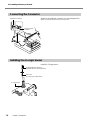
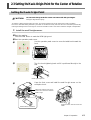
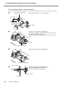
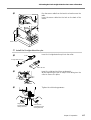
Rotary Axis Unit for MDX-40
ZCL-40
User's Manual
Thank you very much for purchasing this product.
➢ To ensure correct and safe usage with a full understanding of this product's performance, please be
sure to read through this manual completely and store it in a safe location.
➢ Unauthorized copying or transferral, in whole or in part, of this manual is prohibited.
➢ The contents of this operation manual and the specifications of this product are subject to change
without notice.
➢ The operation manual and the product have been prepared and tested as much as possible. If you
find any misprint or error, please inform us.
➢ Roland DG Corp. assumes no responsibility for any direct or indirect loss or damage which may
occur through use of this product, regardless of any failure to perform on the part of this product.
➢ Roland DG Corp. assumes no responsibility for any direct or indirect loss or damage which may
occur with respect to any article made using this product.
Contents
To Ensure Safe Use ..................................................................................................................... 2
Chapter 1 Introduction ........................................................................................................................ 5
1-1 About This Manual ................................................................................................................................................. 6
1-2 About This Machine ............................................................................................................................................... 7
What You Can Do with This Machine .............................................................................................. 7
Part Names and Functions ............................................................................................................... 8
Chapter 2 Preparation ......................................................................................................................... 9
2-1 Included Items ...................................................................................................................................................... 10
2-2 Installing the Rotary Axis Unit .......................................................................................................................... 11
Installing the Rotary Axis Unit ....................................................................................................... 11
Connecting the Connector ............................................................................................................ 12
Installing the Z-origin Sensor ......................................................................................................... 12
2-3 Setting the Y-axis Origin Point for the Center of Rotation ....................................................................... 13
Setting the Y-axis Origin Point ....................................................................................................... 13
Chapter 3 Operation .......................................................................................................................... 23
3-1 Getting Ready for Cutting Using the Rotary Axis ....................................................................................... 24
Dimensions of Workpieces Installable and Start Location ............................................................. 24
3-2 Loading a Workpiece ........................................................................................................................................... 25
Loading a Workpiece Less Than 120 mm in Length ....................................................................... 25
Loading a Workpiece 120 mm or Longer in Length ...................................................................... 30
3-3 Installing a Tool and Setting the Cutting-start Location ............................................................................. 36
Installing a Tool ............................................................................................................................. 36
Setting the Cutting-start Location ................................................................................................... 36
3-4 Changing the Angle of Cutting .......................................................................................................................... 38
Chapter 4 Appendix ........................................................................................................................... 41
4-1 Maintenance .......................................................................................................................................................... 42
Daily Care ..................................................................................................................................... 42
Replacing the Center Drill ............................................................................................................. 42
4-2 What to Do If ....................................................................................................................................................... 43
The machine doesn't run. .............................................................................................................. 43
The cutting results are not attractive. ............................................................................................. 43
What to Do If an Error Message Appears ....................................................................................... 43
Redo the setting the Y origin point at the center of rotation........................................................... 43
4-3 Specifications ......................................................................................................................................................... 44
Main Unit Specifications ............................................................................................................... 44
Copyright© 2004 Roland DG Corporation
http://www.rolanddg.com/
1
To Ensure Safe Use
Improper handling or operation of this machine may result in injury or damage to property.
Points which must be observed to prevent such injury or damage are described as follows.
About
WARNING and
WARNING
CAUTION Notices
Used for instructions intended to alert the user to the risk of death or severe
injury should the unit be used improperly.
Used for instructions intended to alert the user to the risk of injury or material
damage should the unit be used improperly.
CAUTION
* Material damage refers to damage or other adverse effects caused with respect to the home and all its furnishings, as well to domestic animals or pets.
About the Symbols
The
symbol alerts the user to important instructions or warnings. The specific meaning of
the symbol is determined by the design contained within the triangle. The symbol at left means
"danger of electrocution."
The
symbol alerts the user to items that must never be carried out (are forbidden). The
specific thing that must not be done is indicated by the design contained within the circle. The
symbol at left means the unit must never be disassembled.
The symbol alerts the user to things that must be carried out. The specific thing that must be
done is indicated by the design contained within the circle. The symbol at left means the powercord plug must be unplugged from the outlet.
Incorrect operation may cause injury
WARNING
2
Be sure to follow the operation procedures described in this manual.
Failure to follow the procedures may cause sudden operation or the like of the machine, which
may result in unexpected injury.
Never allow children near the machine.
The machine includes locations and components
that pose a danger to children, and major accident, including injury, blindness, or choking, may
occur.
Never allow anyone unfamiliar with the
usage or handling of the machine to touch
the machine.
Touching a dangerous location may cause sudden operation or the like of the machine, which
may lead to an unexpected accident.
Do not disassemble, repair, or modify.
Doing so may lead to fire or abnormal operation resulting in injury.
To Ensure Safe Use
Danger of electrical short, shock, electrocution, or fire
WARNING
In the event of an abnormal state (such as
smoke or sparks, odor or burning or unusual noise), immediately unplug the
power cord.
Failure to do so may result in fire, electrical
shock, or electrocution. Immediately disconnect
the power cord and contact your Roland DG
Corp. service center.
Important Notes on Cutting
CAUTION
Do not touch the tip of the cutting tool
with your fingers.
Doing so may result in injury.
Fasten the spindle, tool, and workpiece securely in place.
Otherwise they may come loose during cutting,
resulting in injury.
Never attempt operation while wearing a
necktie, necklace, loose clothing, or the
like.
They may become caught in the tool, resulting
in injury.
Do not insert the fingers between the rotary axis unit and the workpiece.
The fingers may be pinched, resulting in injury.
3
4
Chapter 1
Introduction
5
1-1 About This Manual
This document is the user's manual for the ZCL-40 (rotary axis unit). It describes how to install the rotary axis unit, and
how to carry out cutting using the unit. For information on operations such as how to switch the power on and off, how
to start the operation-panel screen, and how to start and stop cutting, read the user's manual for the cutting machine.
6
Chapter 1 Introduction
1-2 About This Machine
What You Can Do with This Machine
This is a rotary axis unit compatible with the MDX-40. By adding an axis of rotation (A axis) to the MDX-40, it makes
it possible to perform four-axis machining operations such as multiple-surface cutting.
Chapter 1 Introduction
7
1-2 About This Machine
Part Names and Functions
Rotary axis unit
Chuck-tightening knob
Workpiece chuck
This is a vise-type workpiece chuck. You
turn the chuck-tightening knob to secure
the workpiece in place.
Angle-adjustment dial
This changes the angle of the rotary axis unit. Each tick of the scale
corresponds to 15 degrees of tilt.
Live center
This supports the loaded workpiece.
Adjuster lock
Core-support adjuster
Angle-fixing control
This keeps the rotary axis unit immobile
at the set angle. To change the angle of
the rotary axis unit, pull the control back
toward you.
Core support
Core-support retaining lever
This secures the location of the core support
in place to match the length of the workpiece.
Operation panel screen
When the rotary axis unit is installed, the operation-panel screen shows the following items.
A-axis rotation buttons
This display the present coordinate
value (workpiece coordinate system)
for the A axis.
A-axis coordinate
This displays the present
coordinate value for the
A axis.
8
Workpiece Drilling
Workpiece Length
This displays a dialog box for drilling a hole
to support the workpiece.
This displays a dialog box for entering the
length.
☞ P.25 "3-2 Loading a Workpiece"
☞ P.25 "3-2 Loading a Workpiece"
Chapter 1 Introduction
Chapter 2
Preparation
9
2-1 Included Items
The following items are included with the machine. Make sure they are all present and accounted for.
10
Y-origin sensors
(large and small)
Z-origin sensor
Y-origin detection pin
Center drill
Live center
Hexagonal wrench
Cap screws
(for securing Z-origin sensor)
User's manual
Chapter 2 Preparation
2-2 Installing the Rotary Axis Unit
Installing the Rotary Axis Unit
CAUTION
Before you carry out this operation, switch off the power to the cutting machine.
Failing to do so may result in sudden movement of the cutting machine, causing the hands
or fingers to become caught and resulting in injury.
CAUTION
When installing the rotary axis unit, be careful not to let it drop or fall.
Doing so may result in injury.
Procedure
➊ If a tool is installed, then remove it.
➋
Switch on the power to the cutting machine to start it.
The VIEW light illuminates and the table moves back toward the
front.
➌
Turn off the processing machine and unplug the power cord.
➍
Remove the table from the cutting machine.
Hexagonal wrench
(included with the cutting machine)
Table
➎
Attach the rotary axis unit.
Use the mounting screws for the table to secure it in place.
Rotary axis unit
Line up the holes on the rotary axis unit shown in
the figure with the holes on the cutting machine
also shown in the figure, then attach.
Chapter 2 Preparation
11
2-2 Installing the Rotary Axis Unit
Connecting the Connector
Attach to the expansion connector on the cutting machine.
Expansion connector
Attach it securely, so that it will not come loose.
Rotary axis unit
connector
Installing the Z-origin Sensor
Install the Z-origin sensor.
Large hexagonal screwdriver
(included with the cutting machine)
Cap screw
(for securing Z-origin sensor)
Z-origin sensor
12
Chapter 2 Preparation
2-3 Setting the Y-axis Origin Point for the Center of Rotation
Setting the Y-axis Origin Point
CAUTION
Do not touch the tip of the live center and center drill with your fingers.
Doing so may result in injury.
To perform cutting using the rotary axis unit, you need to set the Y-axis origin point at the center of rotation.
Be sure to make this setting whenever you install or reinstall the rotary axis unit. We also recommend periodically
redoing the setting for the Y-axis origin to correct for deviation of the Y axis due to seasonal changes in temperature.
1. Install the small Y-origin sensor.
➊ Start the machine.
Press the VIEW button to make the VIEW light go out.
➋ Start the operation panel screen.
Use the operation-panel screen to move the table back toward the
➌
front.
➍
Turn the chuck-tightening knob until it is positioned directly to the
side.
Chuck-tightening knob
➎
Open the front cover and install the small Y-origin sensor on the
workpiece chuck.
Install it so that the holes in the
sensor are at the front and back.
Small Y-origin
Install with this orientation.
Align the sensor with the notch and
install.
Chapter 2 Preparation
13
2-3 Setting the Y-axis Origin Point for the Center of Rotation
2. Use the live center to secure the sensor.
➊
2. Turn the handle to extend
the end about 5 mm.
Mount the live center on the core support.
1. Loosen
About 5 mm
3. Insert
Core support
Live center
➋
Loosen the core-support retaining lever.
Move the core support and bring the live center into contact with the small Y-origin sensor.
Line up the center hole of sensor and the tip of the live center and
install.
Core support
Core-support retaining lever
➌
Tighten the core-support retaining lever.
Core-support retaining lever
➍
2. Tighten completely
1. Turn
Turn the core-support adjuster half a turn.
Tighten the adjuster lock completely.
Make sure to fasten the sensor securely.
Core-support adjuster
Adjuster lock
14
Chapter 2 Preparation
2-3 Setting the Y-axis Origin Point for the Center of Rotation
➎
Pass here
Run the sensor cable from the back to a location over the
table.
Insert the sensor cable into the hole on the back of the
sensor.
Insert
Sensor cable
3. Install the Y-origin detection pin.
➊
Collet
Insert the Y-origin detection pin into the collet.
Y-origin detection pin
About 30 mm
➋
Insert the collet and tool from underneath.
While supporting the pin to keep if from falling, turn the
collet to secure it in place.
➌
Tighten the collet using spanners.
Large wrench
(included with the
cutting machine)
Small wrench
(included with the
cutting machine)
Chapter 2 Preparation
15
2-3 Setting the Y-axis Origin Point for the Center of Rotation
4. Use the operation-panel screen for make the setting for the Y-axis origin point.
➊ Close the front cover.
Press the VIEW button to make the VIEW light go out.
➋
Use the operation panel screen to select [Set the Y origin at the center of
rotation].
Select [Start Detection].
➌
Click [Continue].
The Y-origin detection pin automatically
makes contact with the sensor.
➍
When the screen appears, open the front cover.
Rotate the spindle half a turn.
Spindle
Spindle
➎
Close the front cover.
Click [Continue].
The Y-origin detection pin automatically
makes contact with the sensor, and the Y origin point for the rotary axis unit is set, again.
Next, the screen shown in the figure appears.
16
Chapter 2 Preparation
2-3 Setting the Y-axis Origin Point for the Center of Rotation
➏
Open the front cover.
Turn the core-support retaining lever to move the core
support
Core support
Core-support retaining lever
➐
Detach the sensor cable and the small Y-origin sensor.
5. Install the large Y-origin sensor.
➊
1. Loosen
2. Turn
Loosen the adjuster lock.
Turn the core-support adjuster to extend the end about 5
mm.
About 5 mm
Core-support adjuster
Adjuster lock
➋
Install the large Y-origin sensor on the workpiece chuck.
Move the core support, expand the workpiece chuck, then install
the large Y-origin sensor.
Workpiece chuck
Install it so that the holes in the
sensor are at the front and back.
Install with this
orientation.
Core-support
Align the sensor with the notch and
install.
Chapter 2 Preparation
17
2-3 Setting the Y-axis Origin Point for the Center of Rotation
➌
Move the core support and bring the live center into contact with the large Y-origin sensor.
Tighten the core-support retaining lever.
Line up the center hole of sensor and the tip of the live center and
install.
Core support
Core-support retaining lever
2. Tighten completely
1. Turn
➍
Turn the core-support adjuster half a turn.
Tighten the adjuster lock completely.
Make sure to fasten the sensor securely.
Core-support adjuster
Adjuster lock
➎
Pass here
Insert
➏ Close the front cover.
18
Chapter 2 Preparation
Insert the sensor cable into the hole on the back of the
sensor.
2-3 Setting the Y-axis Origin Point for the Center of Rotation
6. Use the operation-panel screen for make the setting for the Y-axis origin point.
➊
Click [Continue].
The Y-origin detection pin automatically makes contact with the sensor.
➋
When the screen appears, open the front cover.
Rotate the spindle half a turn.
Spindle
Spindle
➌
Close the front cover.
Click [Continue].
The Y-origin detection pin automatically makes contact with the sensor, and the Y origin point for the rotary axis unit is set, again.
Next, the screen shown in the figure appears.
➍
Open the front cover.
Turn the core-support retaining lever to move the core
support.
Core-support
Core-support retaining lever
Chapter 2 Preparation
19
2-3 Setting the Y-axis Origin Point for the Center of Rotation
➎
➏
Detach the sensor cable and the large Y-origin sensor.
Z-origin sensor
➐
Insert the sensor cable into the Z-origin sensor.
Close the front cover.
Click [Continue].
The Y-origin detection pin automatically makes contact with the Z-origin sensor.
20
Chapter 2 Preparation
2-3 Setting the Y-axis Origin Point for the Center of Rotation
7. Detach the Y-origin detection pin, collet, live center.
➊ Open the front cover.
➋
Large wrench
(included with the
cutting machine)
➌
Detach the Y-origin detection pin, and collet.
Small wrench
(included with the
cutting machine)
2. Turn
1. Loosen
3. Detach
Loosen the adjuster lock.
Turn the core-support adjuster all the way, then detach the
live center.
Core-support adjuster
Adjuster lock
Chapter 2 Preparation
21
22
Chapter 3
Operation
23
3-1 Getting Ready for Cutting Using the Rotary Axis
Dimensions of Workpieces Installable and Start Location
Dimensions of Workpieces Installable
Example : Loading a Square Block
A workpiece that fits within the range of a 42.5 mm radius from the center of the rotary axis by 135 mm long can be
loaded.
The figure shows the maximum size when loading a workpiece that is 40 mm thick.
Workpiece
Workpiece
Objects that fit within the range of a 42.5 mm
radius from the center of the rotary axis
75 mm
40 mm
40 mm
Center of the rotary axis
Maximum 135 mm
75 mm
➢ Maximum width when loading a workpiece measuring 40 mm thick : 75 mm
(The maximum width varies according to the thickness of the workpiece.)
➢ Workpiece thickness that can be held by the workpiece chuck : 12 to 40 mm
➢ Loadable workpiece length : Maximum 135 mm
The Locations of the Origin Points
When you perform cutting using the rotary axis, you make the respective settings for the X-axis, Y-axis, Z-axis, and Aaxis origin points. The X-axis origin becomes the start location for cutting. Make the setting to match the workpiece, so
that the workpiece does not strike the rotary axis unit during cutting. Align the Y and Z origins with the center of the
rotary axis. The Z-axis origin is to be set so as to match the length of the tool. Set the A-axis origin when you want to
specify the start location for the direction of rotation.
To perform cutting using the rotary axis, you need to set the Y-axis origin at the center of rotation. Be sure to make this
setting when you install the rotary axis unit for the first time, and whenever you reinstall it. Make the setting again
whenever displacement of the Y origin becomes a concern during continuous use.
☞ P.13 "Setting the Y-axis Origin Point for the Center of Rotation"
24
Chapter 3 Operation
3-2 Loading a Workpiece
Loading a Workpiece Less Than 120 mm in Length
The mounting method varies according to the length of the workpiece you're loading. When you're loading a workpiece
measuring less than 120 mm, follow the steps below.
1. Entering the length of the workpiece at the operation panel screen.
➊
Click [Workpiece Length].
➋
Enter the length of the mounted workpiece.
Click [OK].
2. Carry out the preparations for securing the workpiece in place.
➊ Close the front cover.
Press the VIEW button to make the VIEW light go out.
➋
Turn the workpiece chuck to a position where the chucktightening knob is facing upward.
Chuck-tightening knob
➌
Open the front cover.
Secure the workpiece in place on the workpiece chuck.
Fasten the workpiece securely, so that it will not fall.
Chuck-tightening knob
Workpiece
Chapter 3 Operation
25
3-2 Loading a Workpiece
➍
2. Turn the handle to extend
the end about 5 mm.
Mount the center drill on the core support.
1. Loosen
About 5 mm
3. Insert
Core support
Center drill
➎
Loosen the core-support retaining lever.
Move the core support and bring the tip of the center drill
into contact with the workpiece.
Core-support retaining lever
➏
Tighten the core-support retaining lever.
Core-support retaining lever
26
Chapter 3 Operation
3-2 Loading a Workpiece
3. Drill a hole for retaining the workpiece.
➊
At the operation-panel screen, click [Workpiece Drilling].
➋
Click [Rotate].
The rotary axis starts to turn.
➌
Turn the core-support adjuster slowly
to drill the hole by center drill.
Cut in about 3 mm
from the blade tip.
Core-support adjuster
➍
Click [Stop].
The rotation stops.
➎
Click [Close].
Chapter 3 Operation
27
3-2 Loading a Workpiece
➏
Loosen the core-support retaining lever to move the core
support.
Core support
Core-support retaining lever
➐
Center drill
Turn the core-support adjuster all the way, then detach the
center drill.
Core-support adjuster
28
Chapter 3 Operation
3-2 Loading a Workpiece
4. Use the live center to secure the workpiece in place.
➊
2. Turn the handle to extend
the end about 5 mm.
Mount the live center on the core support.
1. Loosen
About 5 mm
3. Insert
Core support
Live center
➋
Loosen the core-support retaining lever.
Move the core support and bring the live center into contact with the workpiece.
Core-support
Core-support retaining lever
➌
Tighten the core-support retaining lever.
Core-support retaining lever
➍
2. Tighten completely
Adjuster lock
1. Turn
Turn the core-support adjuster half a turn.
Tighten the adjuster lock completely.
Core-support adjuster
Securing the Workpiece in Place
After securing the workpiece in place using the live center, go to the operation-panel screen and rotate the A axis. If
the workpiece and the live center turn together, the workpiece is fastened securely. If the live center does not turn,
loosen the adjuster lock, turn the core-support adjuster, then secure the control in place again with the adjuster lock.
Chapter 3 Operation
29
3-2 Loading a Workpiece
Loading a Workpiece 120 mm or Longer in Length
When you're loading a workpiece measuring 120 mm or longer, follow the steps below.
1. Entering the length of the workpiece at the operation panel screen.
➊
Click [Workpiece Length].
➋
Enter the length of the mounted
workpiece.
Click [OK].
2. Carry out the preparations for securing the workpiece in place.
➊ Close the front cover.
Press the VIEW button to make the VIEW light go out.
➋
Turn the workpiece chuck to a position where the chucktightening knob is facing upward.
Chuck-tightening knob
➌
2. Turn the handle to extend
the end about 5 mm.
Open the front cover.
Mount the center drill on the core support.
1. Loosen
About 5 mm
3. Insert
Center drill
30
Chapter 3 Operation
Core support
3-2 Loading a Workpiece
➍
Secure the workpiece in place on the workpiece chuck.
Fasten the workpiece securely, so that it will not fall.
Workpiece chuck
Workpiece
➎
Loosen the core-support retaining lever.
Move the core support and bring the tip of the center drill
into contact with the workpiece.
Core-support
Core-support retaining lever
Chapter 3 Operation
31
3-2 Loading a Workpiece
3. Drill a hole for retaining the workpiece.
➊
At the operation-panel screen, click [Workpiece Drilling].
➋
Click [Rotate].
The rotary axis starts to turn.
➌
Turn the core-support adjuster slowly
to drill the hole by center drill.
Cut in about 3 mm
from the blade tip.
Core-support adjuster
➍
Click [Stop].
The rotation stops.
➎
32
Chapter 3 Operation
Click [Close].
3-2 Loading a Workpiece
➏
Loosen the core-support retaining lever to move the core
support.
Core-support
Core-support retaining lever
➐
Detach the workpiece once.
➑
Turn the core-support adjuster all the way, then detach the
center drill.
Center drill
Core-support adjuster
Chapter 3 Operation
33
3-2 Loading a Workpiece
4. Use the live center to secure the workpiece in place.
➊
Mount the live center on the core support.
2. Turn the handle to extend
the end about 5 mm.
1. Loosen
About 5 mm
3. Insert
Core support
Live center
➋
Loading the workpiece.
Core support
Core-support retaining lever
➌
Loosen the core-support retaining lever.
Move the core support and bring the live center into contact with the workpiece.
Workpiece-support hole
➍
Line up the workpiece-support hole and the tip of the live center
and attach.
Tighten the core-support retaining lever.
Core support
Core-support retaining lever
34
Chapter 3 Operation
3-2 Loading a Workpiece
➎
2. Tighten completely
Adjuster lock
1. Turn
Turn the core-support adjuster half a turn.
Tighten the adjuster lock completely.
Core-support adjuster
Securing the Workpiece in Place
After securing the workpiece in place using the live center, go to the operation-panel screen and rotate the A axis. If
the workpiece and the live center turn together, the workpiece is fastened securely. If the live center does not turn,
loosen the adjuster lock, turn the core-support adjuster, then secure the control in place again with the adjuster lock.
Chapter 3 Operation
35
3-3 Installing a Tool and Setting the Cutting-start Location
Installing a Tool
CAUTION
Do not touch the tip of the blade with your fingers.
Doing so may result in injury.
Installing a Tool
Follow the instructions in the manual for the cutting machine to install a tool.
Adjust the amount of tool extension to match the size of the workpiece and the cutting depth. Special care is
needed, because the corners may easily strike the tool when rotating the A axis.
Setting the Cutting-start Location
1. Make the setting for X origin point.
➊ Close the front cover.
Press the VIEW button to make the VIEW light go out.
➋
➌
Use the operation panel screen to move the spindle to the cuttingstart location.
Set the cutting-start location so that the neither the tool nor the
spindle strikes the workpiece chuck during cutting.
Select [Set the X origin here].
Click [Set].
The start location in the X origin has now been
set.
36
Chapter 3 Operation
3-3 Installing a Tool and Setting the Cutting-start Location
2. Make the setting for Z origin point.
➊ Make sure to insert the sensor cable to Z-origin sensor.
➋
➌
Using the operation panel screen, select
[Set the Z origin at the center of rotation].
Select [Start Detection].
Click [Continue].
The tool automatically makes contact with the
sensor, and the Z-axis origin point is set.
3. Make the setting for A origin point.
➊
➋
Use the operation-panel screen to rotate the workpiece to the cutting-start location.
Select [Set the A origin here].
Click [Set].
The start location in the A origin has now been
set.
Chapter 3 Operation
37
3-4 Changing the Angle of Cutting
➊ If the cutter installed, detach it.
➋
Loosen the screws shown in the figure.
Hexagonal wrench
➌
Large hexagonal driver
(included with the
cutting machine)
➍
Detach the screw shown in the figure.
Pull the angle-fixing control.
Turn to a position not lined up with the groove.
Groove
Angle-fixing control
➎
Scale
Turn to align with the scale on the angle-adjustment dial.
Each tick of the scale corresponds to 15 degrees of tilt.
Angle-adjustment dial
38
Chapter 3 Operation
3-4 Changing the Angle of Cutting
➏
Press the angle-fixing control.
When it clicks into place, the rotary axis is secured in
position.
Angle-fixing control
➐
Tighten the screws shown in the figure.
Hexagonal wrench
Chapter 3 Operation
39
40
Chapter 4
Appendix
41
4-1 Maintenance
Daily Care
➢ This machine is a precision device, and is sensitive to dust and dirt. Perform cleaning on a daily basis.
➢ Never use a solvent such as thinner or benzine.
➢ Clean cuttings carefully.
➢ To clean the cover, use a dry cloth to wipe it.
➢ Never attempt to oil or lubricate the machine.
Replacing the Center Drill
If the tip of the center drill becomes worn, change the orientation of the tip.
Replacement
➊
Drill holder
Loosen the screw for the drill holder and take out the
center drill.
Center drill
Screw
Small hexagonal driver
(included with the cutting
machine)
New tip
➋
Reverse the orientation, reinsert, then tighten the screw
securely.
Insert fully, until the inserted end touches the bottom of the drill
holder.
Screw
New tip
42
Chapter 4 Appendix
4-2 What to Do If
The machine doesn't run.
Is the rotary axis unit cable connected?
Connect the rotary axis unit cable securely.
Redo the setting the Y origin point at the center of rotation
Setting the Y-axis origin at the center of the rotary
axis.
1. Close the front cover.
Press the VIEW button to make the VIEW light go out.
The cutting results are not attractive.
Has correction of the origin point for the rotary axis
been performed?
2. Use the operation panel screen to select [To Y Center].
Click [Move].
The spindle moves to the center of the rotary axis.
If the origin point for the rotary axis unit is displaced, the
cutting results may show seams or differences in level, or
the shape may be irregular. Also, overall thickness may be
uneven, or uncut areas may remain. If this happens, then
redo the setting for the rotary-axis origin point.
☞ P.13"Setting the Y-axis Origin Point for the Center of Rotation"
3. Select [Set the Y origin here].
Click [Set].
What to Do If an Error Message Appears
[A-axis limit-switch error. Please switch off machine
power.]
An error occurred during initialization of the machine.
This message may appear if head movement is obstructed
during initialization at startup. Switch the power off, then
back on.
Chapter 4 Appendix
43
4-3 Specifications
Main Unit Specifications
ZCL-40
Maximum angle of rotation
Loadable workpiece size*
±18x10 ˚ (± 5000 rotations)
Workpiece thickness holdable
by workpiece chuck
Loadable workpiece weight
Control methods
Feed rate
Mechanical resolution
Rotary-axis tilt angle
Dimensions
12 to 40 mm (1/2 to 1-5/8 in.)
Weight
Packed dimensions
6.2 Kg (13.7 lb)
Packed weight
Accessories
9 Kg (20 lb)
5
Items within the range of a 42.5 mm (1-11/16 in.) radius from the center of the rotary
axis by long 135 mm (5-3/8 in.)
0.5 Kg (1.1 lb) (Maximum workpiece moment of inertia 6x10⁻⁴ kgm2)
4-axis control (3-axis simultaneous control)
11.79 rpm
0.0225 deg.
0 deg. to 90 deg. (in increments of 15 deg.)
357 (W) x 305 (D) x 129 (H) mm
(14-1/16 (W) x 12 (D) x 5-1/8 (H) in.)
490 (W) x 440 (D) x 260 (H) mm
(19-3/8 (W) x 17-3/8 (D) x 10-1/4 (H) in.)
Y-origin sensors (large and small), Z-origin sensor, Y-origin detection pin, center drill,
live center, hexagonal wrench, cap screws (for securing Z-origin sensor), user's manual
The cutting range of the MDX-40 when installed with ZCL-40 rotary axis unit is as follows.
189.5 (X) x 305 (Y) x 60 (Z) mm
(7-1/2 (X) x 12 (Y) x 2-3/8 (Z) in.)
*The range that can actually be cut is limited by the following factors.
• Amount of tool extension
• Interference between the loaded workpiece and the tool or spindle
44
Chapter 4 Appendix
4-2 Specifications
Rotary Axis Unit Schematic
Unit : mm
90
90deg. rotation
(in increments 15deg.)
Handle
65
94
27.5
196.6
26
le
ho
wcre
4s n
M catio
lo
φ
33
6
φ2
Workpiece-chuck mounting surface
(2-mm countersunk surface)
Chapter 4 Appendix
45
4-2 Specifications
Rotary Axis Unit Schematic (Top View)
152.5
285
305
270
286.5
17.5
44.5
216
356.5
Rotary Axis Unit Schematic (Front View)
135 (Maximum width)
65
129
40(Max.)
12(Min.)
10 (Clamp-area depth)
Clamp area
ting
75
mu
ut
mc
40
5
φ8
46
Chapter 4 Appendix
axi
(M
a)
are
4-2 Specifications
152.5 (Center location)
305 (Y-axis stroke)
Installed on the MDX-40 (Top View)
5 (Distance from clamp end face)
115.5
189.5
(X-axis stroke)
305
60 (Z-axis stroke)
10
125 (Maximum height)
Installed on the MDX-40 (Front View)
65
(Workpiece center height)
Chapter 4 Appendix
47
48
R1-041217