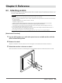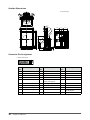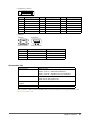
1
Important
Please read PRECAUTIONS, this User’s Manual and Setup Manual
(separate volume) carefully to familiarize yourself with safe and effective
usage.
• Please read the Setup Manual (separate volume)
• The latest User’s Manual is available for download from our site:
http://www.radiforce.com
Product specification may vary with sales areas.
Confirm the specification in the manual written in language of the region of purchase.
• It shall be assured that the final system is in compliance to IEC60601-1-1 requirement.
• Power supplied equipment can emit electromagnetic waves, that could influence, limit or result in
malfunction of the monitor.
Install the equipment in a controlled environment, where such effects are avoided.
• This is a monitor intended for use in a medical image system. It does not support the display of
mammography images for diagnosis.
Copyright© 2009 EIZO NANAO CORPORATION All rights reserved.
No part of this manual may be reproduced, stored in a retrieval system, or transmitted, in any form or by
any means, electronic, mechanical, or otherwise, without the prior written permission of EIZO NANAO
CORPORATION.
EIZO NANAO CORPORATION is under no obligation to hold any submitted material or information
confidential unless prior arrangements are made pursuant to EIZO NANAO CORPORATION’s receipt of
said information.
Although every effort has been made to ensure that this manual provides up-to-date information, please
note that EIZO monitor specifications are subject to change without notice.
Apple, Macintosh and Mac OS are registered trademarks of Apple Inc.
VGA is a registered trademark of International Business Machines Corporation.
Windows and Windows Vista are registered trademarks of Microsoft Corporation in the United States and other countries.
The round gothic bold bit map font used for this product is designed by Ricoh.
DisplayPort icon and VESA are trademarks and registered trademarks of Video Electronics Standards Association.
PowerManager is a trademark of EIZO NANAO CORPORATION.
EIZO, EIZO Logo, RadiCS, RadiForce, RadiNET and ScreenManager are registered trademarks of EIZO NANAO
CORPORATION in Japan and other countries.
All other trademarks are the properties of their respective owners.
Notice for this monitor
This product is suited to display medical images of such modalities as MRI and CT. It does not support the display of
mammography images for diagnosis.
This product has been adjusted specifically for use in the region to which it was originally shipped. If the product is
used outside the region, it may not operate as specified in the specifications.
This product may not be covered by warranty for uses other than those described in this manual.
The specifications noted in this manual are only applicable for power cords and signal cables specified by us.
Use optional products manufactured or specified by us with this product.
As it takes about 30 minutes for the performance of electrical parts to stabilize, adjust the monitor 30 minutes or more
after the monitor power has been turned on.
In order to suppress the luminosity change by long-term use and to maintain the stable luminosity, use of a monitor in
lower brightness is recommended.
When the screen image is changed after displaying the same image for extended periods of time, an afterimage may
appear. Use the screen saver or power save function to avoid displaying the same image for extended periods of time.
Periodic cleaning is recommended to keep the monitor looking new and to prolong its operation lifetime. (Refer to
“Cleaning” on the next page.)
The screen may have defective pixels. These pixels may appear as slightly light or dark area on the screen. This is due
to the characteristics of the panel itself, and not the product.
The backlight of the LCD panel has a fixed life span. When the screen becomes dark or begins to flicker, please
contact your dealer.
Do not press on the panel or edge of the frame strongly, as this may result in the display malfunction, such as the
interference patterns, etc. If pressure is continually applied to the LCD panel, it may deteriorate or damage your LCD
panel. (If the pressure marks remain on the LCD panel, leave the monitor with a white or black screen. The symptom
may disappear.)
Do not scratch or press on the panel with any sharp objects, such as a pencil or pen as this may result in damage to the
panel. Do not attempt to brush with tissues as this may scratch the LCD panel.
When the monitor is cold and brought into a room or the room temperature goes up quickly, dew condensation
may occur inside and outside the monitor. In that case, do not turn the monitor on and wait until dew condensation
disappears, otherwise it may cause some damages to the monitor.
Cleaning
Attention
• Never use any solvents or chemicals, such as thinner, benzene, wax, alcohol, disinfectant, and abrasive cleaner,
which may damage the cabinet or LCD panel.
NOTE
• Optional ScreenCleaner is recommended for cleaning the panel surface.
● LCD Panel
• Clean the LCD panel with a soft cloth such as cotton cloth or lens cleaning paper.
• Remove persistent stains gently with a cloth dampened with a little water, and then clean the LCD
panel again with a dry cloth for better finishing.
● Cabinet
• Clean the cabinet with a soft cloth dampened with a little mild detergent.
To use the monitor comfortably
• An excessively dark or bright screen may affect your eyes. Adjust the brightness of the monitor
according to the environmental conditions.
• Staring at the monitor for a long time tires your eyes. Take a 10-minute rest every hour.
CONTENTS
Cover
. ............................................................ 1
Chapter 3 Setting Monitor................................. 21
Notice for this monitor.............................................. 3
3-1. Enabling/Disabling Mode Selection
[Mode Preset]...................................................21
CONTENTS.............................................................. 5
Chapter 1 Introduction........................................ 6
1-1. Features............................................................. 6
1-2. Switches and Indicators.................................. 7
1-3. Utility Disk......................................................... 7
●Disk contents and software overview................. 7
●To RadiCS LE or
3-2. Locking Switches [Key Lock]........................21
3-3. Setting the EIZO Logo Display [Logo]......... 22
3-4. Setting Orientation ....................................... 22
●Using Image Rotation Function
[Image Rotation]................................................ 22
3-5. Setting Language [Language]...................... 23
ScreenManager Pro for Medical......................... 7
3-6. Setting the Display Position of the
Adjustment Menu [Menu Position]............... 23
1- 4. Basic Operation and Functions...................... 8
3-7. Restoring the Default Setting....................... 24
Basic operation of Adjustment menu.................. 8
Functions................................................................ 9
Chapter 2 Adjusting Screen.............................. 10
2-1. Setting Screen Resolution................................10
●To reset color adjustment values
[Color Reset]......................................................24
●To reset all adjustments to the factory default
settings [All Reset].............................................24
Compatible Resolutions/Frequencies................10
Chapter 4 Power Saving Function.................... 25
Setting Resolution................................................10
4-1. Setting the Power Saving [Power Save]...... 25
●Windows Vista...................................................10
●Windows XP.......................................................10
●Mac OS X...........................................................10
2-2. Displaying Screen Correctly..........................11
4-2. Setting Power Indicator [Power Indicator].. 25
Chapter 5 Troubleshooting............................... 26
Chapter 6 Reference.......................................... 29
Digital Input...........................................................11
6-1. Attaching an Arm........................................... 29
Analog Input..........................................................11
6-2. Connecting More than Two PCs to the
Monitor............................................................ 30
2-3. Color Adjustment............................................15
●To select the display mode (CAL Switch)..........15
●To perform advanced adjustments....................15
●Adjustment items in each mode.........................16
●To adjust the brightness [Brightness].................17
●To adjust the contrast [Contrast]........................17
●To adjust the color temperature
[Temperature].....................................................17
●To adjust the gamma value [Gamma]................18
●To adjust the hue [Hue]......................................18
●To adjust the color saturation [Saturation].........18
●To enhance the outline of the image
[Outline Enhancer].............................................19
●To adjust the gain value [Gain]...........................19
●To adjust six colors [6 Colors]............................19
2-4. Displaying Lower Resolutions...................... 20
●To switch the input signal.................................. 30
●To set input signal selection [Input Selection]....31
6-3. Making Use of USB (Universal Serial Bus).. 32
●Required System Environment......................... 32
●Connection Procedure
(Setup of USB Function)................................... 32
6-4. Displaying Monitor Information................... 33
●Displaying signal information [Signal Info]........ 33
●Displaying monitor information [Monitor Info]... 33
6-5. Specifications................................................. 34
6-6. Glossary.......................................................... 38
6-7. Preset Timing.................................................. 40
FCC Declaration of Conformity.......................... 41
EMC Information.................................................. 42
●To change screen size [Screen Size]................ 20
CONTENTS
Chapter 1 Introduction
Thank you very much for choosing an EIZO Color Monitor.
1-1. Features
•
•
•
•
Resolution: 2M pixels (Portrait : 1200 × 1600 dots (H × V))
Applicable to DisplayPort (applicable to 8 bit or 10 bit, not applicable to audio signals)
3 signal input terminals (DVI-I x 2, DisplayPort x 1)
CAL Switch function for selecting an optimal calibration mode
“2-3. To select the display mode (CAL Switch)” (page 15)
• DICOM mode (CAL Switch function) (page 38)
• The quality control software “RadiCS LE” (for Windows) used to calibrate the monitor is included
“1-3. Utility Disk” (page 7)
• The software “ScreenManager Pro for Medical” (for Windows) to adjust the screen using the mouse
and keyboard is included
“1-3. Utility Disk” (page 7)
• Frame Synchronous mode supported (59 - 61 Hz)
• HDCP (High-bandwidth Digital Content Interface)
Chapter 1 Introduction
1-2. Switches and Indicators
Adjustment menu
Switch
1
2
3
4
5
switch
switch
switch
switch
5.
switch
6.
switch
7. Power Indicator
Indicator status
Operation status
1.
2.
3.
4.
Green
The screen is displayed
Orange
Power saving
Off
Main Power Switch / Power Switch off
6
7
1-3. Utility Disk
An “EIZO LCD Utility Disk” (CD-ROM) is supplied with the monitor. The following table shows the
disk contents and the overview of the software programs.
● Disk contents and software overview
The disk includes application software programs for adjustment, and User’s Manual. Refer to “Readme.
txt” file on the disk for software startup procedures or file access procedures.
Item
Overview
A “Readme.txt” file
RadiCS LE (for Windows)
RadiCS LE is quality control software used to calibrate the
monitor and manage the calibration history. (A PC must be
connected to the monitor with the supplied USB cable.) Refer
to the description later.
ScreenManager Pro for Medical
(for Windows)
A utility software program to control monitor adjustments from
a PC using its mouse and keyboard. (A PC must be connected
to the monitor with the supplied USB cable.) Refer to the
description later.
User’s Manual (PDF file)
● To RadiCS LE or ScreenManager Pro for Medical
Refer to the corresponding User’s Manual on the CD-ROM disk in order to install and use the software.
When using this software, you will need to connect a PC to the monitor with the supplied USB cable. For
more information refer to the “6-3. Making Use of USB (Universal Serial Bus)” (page 32).
Chapter 1 Introduction
1- 4. Basic Operation and Functions
Basic operation of Adjustment menu
1 Displaying Adjustment Menu
Press
.
The adjustment menu appears.
Menu title
Current mode
Item
Settings
Menu
2 Adjusting/Setting
1. Choose a menu to adjust/set with
, and press
.
2. Choose an item to adjust/set with
, and press
.
3. Adjust/set the selected item with
, and press
3 Exiting
Press
a few times.
The adjustment menu finishes.
Chapter 1 Introduction
.
Functions
The following table shows all the Adjustment menu’s adjustment and setting menus.
Main Menu
Color
Item
Adjusting/Setting
“2-3. Color Adjustment” (page 15)
Brightness
Contrast
Temperature
Gamma
Advanced
Settings
Hue
Saturation
Outline Enhancer
Gain
6 Colors
“3-7. Restoring the Default Setting”
(page 24)
Color Reset
Screen
“2-4. Displaying Lower Resolutions”
(page 20)
“3-4. Setting Orientation” (page 22)
Screen Size
Image Rotaion
Analog
Adjustment
Auto Adjustment
Range Adjustment
“2-2. Displaying Screen Correctly”
(page 11)
Clock
Phase
Hor.Position
Ver.Position
PowerManager
Menu Settings
Tools
Power Save
“4-1. Setting the Power Saving” (page 25)
Power Indicator
“4-2. Setting Power Indicator” (page 25)
Language
“3-5. Setting Language” (page 23)
Menu Position
“3-6. Setting the Display Position of the
Adjustment Menu” (page 23)
Input Selection
Mode Preset
Signal Info
“6-2. Connecting More than Two PCs to the
Monitor” (page 30)
“3-1. Enabling/Disabling Mode Selection”
(page 21)
“6-4. Displaying Monitor Information”
(page 33)
Monitor Info
All Reset
“3-7. Restoring the Default Setting”
(page 24)
* The adjusting/setting function on the <Color> menu depend on the selected Color mode (page 16). The above table
shows the sub menus when the “Custom” mode is selected (See “2-3. Color Adjustment” (page 15)).
Chapter 1 Introduction
Chapter 2 Adjusting Screen
2-1. Setting Screen Resolution
Compatible Resolutions/Frequencies
For details on compatible resolutions, refer to “Compatible Resolutions/Frequencies” in the Setup
Manual.
Setting Resolution
When you connect the monitor to the PC and find that the resolution is improper, or when you want to
change the resolution, follow the procedure below.
● Windows Vista
1. Right-click the mouse anywhere on the desktop except for icons.
2. From the displayed menu, click “Personalize”.
3. On the “Personalization” window, click “Display Settings”.
4. On the “Display Settings” dialog, select the “Monitor” tab and select desired resolution in the
“Resolution” field.
5. Click the “OK” button.
6. When a confirmation dialog is displayed, click “Yes”.
● Windows XP
1. Right-click the mouse anywhere on the desktop except for icons.
2. From the displayed menu, click “Properties”.
3. When the “Display Properties” dialog is displayed, click the “Settings” tab and select desired
resolution for “Screen resolution” under “Display”.
4. Click the “OK” button to close the dialog.
● Mac OS X
1. Select “System Preferences” from the Apple menu.
2. When the “System Preferences” dialog is displayed, click “Displays” for “Hardware”.
3. On the displayed dialog, select the “Display” tab and select desired resolution in the “Resolutions”
field.
4. Your selection will be reflected immediately. When you are satisfied with the selected resolution, close
the window.
10
Chapter 2 Adjusting Screen
2-2. Displaying Screen Correctly
Digital Input
When digital signals are input, images are displayed correctly based on the preset data of the monitor.
When performing advanced adjustment, see “2-3 Color Adjustment” (page 15) and subsequent pages.
Analog Input
Attention
• Wait 30 minutes or more from monitor power on before starting adjustments.
(Allow the monitor to warm up for at least 30 minutes before making adjustments.)
The monitor screen adjustment is used to suppress flickering of the screen or adjust screen position and
screen size correctly according to the PC to be used.
The auto adjustment function works when filling/satisfying all of the following conditions
• When a signal is input into the monitor for the first time or when the resolution or Vertical/
Horizontal Frequency not displayed before is set
• When signals with the vertical resolution over 480 are input
If the screen is not displayed correctly even after performing the auto adjustment, perform the screen
adjustments according to the procedures on the following pages to use the monitor comfortably.
[Adjustment Procedure]
1 Perform the auto adjustment.
● To adjust flickering, screen position, and screen size automatically [Auto Adjustment]
Procedure
1. Choose <Screen> from the Adjustment menu, and press
.
2. Choose <Analog Adjustment> from the <Screen> menu, and press
3. Choose <Auto Adjustment>, and press
.
.
The auto adjustment function works (the message “In Progress” appears) to correctly adjust the flickering, screen
position, and screen size correctly.
When the auto adjustment is completed, a message appears. Select “OK” to confirm the new settings or “Cancel”
to restore the previous settings, and press .
Attention
• This function works correctly when an image is fully displayed over the Windows or Macintosh display area. It
does not work properly when an image is displayed only on a part of the screen (command prompt window, for
example) or when a black background (wallpaper, etc.) is in use.
• This function does not work correctly with some graphics boards.
If the screen is not displayed correctly even after adjusting in step 1 above, perform the adjustments
according to the procedures on the following pages. When the screen is displayed correctly, go to step
5 “To adjust color gradation automatically [Range Adjustment]”.
Chapter 2 Adjusting Screen
11
2 Prepare the display pattern for the analog display adjustment.
Download the “Screen adjustment pattern files” from our site: http://www.radiforce.com
NOTE
• For details and instructions on opening the “Screen adjustment pattern files”, refer to the “Readme.txt” file.
3 Perform the auto adjustment again with the analog screen adjustment pattern
displayed.
● To adjust flickering, screen position, and screen size automatically [Auto Adjustment]
Procedure
1. Display Pattern 1 of the screen adjustment pattern files in full screen on the monitor.
2. Choose <Screen> from the Adjustment menu, and press
.
3. Choose <Analog Adjustment> from the <Screen> menu, and press
.
To proceed with the subsequent adjustments, select an item in <Analog Adjustment> of the <Screen> menu.
4. Choose <Auto Adjustment>, and press
.
The auto adjustment function works (the message “In Progress” appears) to adjust the flickering, screen position,
and screen size correctly.
When the auto adjustment is completed, a message appears. Select “OK” to confirm the new settings or “Cancel”
to restore the previous settings, and press .
If the screen is not displayed correctly even after adjusting in step 3 above, perform the adjustments
according to the procedures on the following pages. When the screen is displayed correctly, go to step
5 “To adjust color gradation automatically [Range Adjustment]”.
12
Chapter 2 Adjusting Screen
4 Perform advanced adjustments for the following using the <Screen> menu of
the <Analog Adjustment>.
Adjust the clock, phase and position, in this order.
● To eliminate vertical bars [Clock]
Procedure
1. Choose <Clock> from the <Analog Adjustment> menu, and press
2. Adjust the clock with
or
.
Press
3. Press
.
slowly so as not to miss the adjustment point.
to exit the adjustment.
When blurring, flickering or bars appear on the screen after adjustment, proceed to [Phase] to remove flickering
or blurring.
● Remove flickering or blurring [Phase]
Procedure
1. Choose <Phase> from the <Analog Adjustment> menu, and press
2. Adjust the phase with
or
.
3. Press
to exit the adjustment.
.
Attention
• Flickering or blurring may not be eliminated depending on your PC or graphics board.
● To correct screen position [Hor.Position] [Ver.Position]
NOTE
• Since the number of pixels and the pixel positions are fixed on the LCD monitor, only one position is provided to
display images correctly. The position adjustment is made to shift an image to the correct position.
Procedure
1. Choose <Hor.Position> or <Ver.Position> from the <Analog Adjustment> menu, and press
2. Adjust the position with
or
.
3. Press
to exit the adjustment.
.
Chapter 2 Adjusting Screen
13
5 Adjust the color gradation.
● To adjust color gradation automatically [Range Adjustment]
Every color gradation (0 to 255) can be displayed by adjusting the signal output level.
Procedure
1. Display Pattern 2 in full screen on the monitor using the screen adjustment pattern files.
2. Choose <Range Adjustment> from the <Analog Adjustment> menu, and press
.
The color gradation is adjusted automatically.
When the auto adjustment is completed, a message appears. Select “OK” to confirm the new settings or “Cancel”
to restore the precious settings, and press .
3. Close the Pattern 2.
14
Chapter 2 Adjusting Screen
2-3. Color Adjustment
● To select the display mode (CAL Switch)
CAL Switch allows you to select easily the adequate mode suitable for the monitor’s application.
CAL Switch mode
Mode
1-DICOM
2-Custom
3-CAL
4-Text
Purpose
Available to display in DICOM mode.
Available for the color settings according to your preference.
Displays the screen adjusted by calibration software.
Suitable for displaying texts for word processing or spreadsheets.
The mode menu
appears.
Procedure
1. Press
.
Mode menu appears at the lower left of the screen.
2. The mode among the list is highlighted in turn each time
is pressed.
You can switch the current mode with
or
while the mode menu is being displayed.
→1-DICOM←→2-Custom←→3-CAL←→4-Text←
NOTE
• The Adjustment menu and the Mode menu cannot be displayed at the same time.
• You can disable a specific mode to be selected. For more information, refer to “3-1 Enabling/Disabling Mode
Selection” (page 21).
● To perform advanced adjustments
The <Color> menu of the Adjustment menu allows you to set and save the independent color adjustment
for each mode.
Attention
• Wait 30 minutes or more from monitor power on before starting the color adjustment.
(Allow the monitor to warm up for at least 30 minutes before making adjustments.)
• Perform the range adjustment first when adjusting color for analog input signals.
(Refer to “To adjust color gradation automatically” on page 14).
• The same image may be seen in different colors on multiple monitors due to their monitor-specific characteristics.
Make fine color adjustment visually when matching colors on multiple monitors.
NOTE
• The values shown in “%” or “K” are available only as reference.
Chapter 2 Adjusting Screen
15
● Adjustment items in each mode
According to the mode selected, the adjustable function differs.
(You can not select any function unavailable for adjustment or setting.)
The adjustments or settings made for each mode are applied to all input signals.
For the adjustment method of each function, refer to subsequent pages.
√: Adjustment available ―: Invalid for adjustment
Icon
Function
1-DICOM
CAL Switch mode
2-Custom*
3-CAL*
4-Text*
Brightness
√
√
√
√
Contrast
―
√
―
√
Temperature
―
√
―
√
Gamma
―
√
―
√
Hue
―
√
―
√
Saturation
―
√
―
√
Outline
Enhancer
―
√
―
√
Gain
―
√
―
―
6 Colors
―
√
―
―
Color Reset
√
√
√
√
* If you adjust the calibration in this mode using the calibration kit exclusive for to this monitor (RadiCS LE as an
accessory shown on page 37), only Brightness and Reset is adjustable.
16
Chapter 2 Adjusting Screen
● To adjust the brightness [Brightness]
The screen brightness is adjusted by changing the brightness of the backlight (Light source from the LCD
back panel).
Adjustable range: 0 to 100%
Procedure
1.
2.
3.
4.
Choose <Color> from the Adjustment menu, and press
.
Choose <Brightness> from the <Color> menu, and press
.
Adjust the brightness with
or
.
Press
to exit the adjustment.
NOTE
• You can also adjust the brightness using
and .
• When your feel the image is bright even if the brightness is set to 0%, adjust the contrast.
● To adjust the contrast [Contrast]
The luminance of the screen is adjusted by varying the video signal level.
Adjustable range: 0 to 100%
Procedure
1.
2.
3.
4.
Choose <Color> from the Adjustment menu, and press
Choose <Contrast> from the <Color> menu, and press
Adjust the contrast with
or
.
Press
to exit the adjustment.
.
.
NOTE
• In the contrast of 100%, every color gradation is displayed.
• When adjusting the monitor, it is recommended to perform the brightness adjustment which may not lose the
gradation characteristics, prior to the contrast adjustment.
• Perform the contrast adjustment in the following cases.
- When you feel the image is bright even if the brightness is set to 0%. (Set the contrast to lower than 100%).
● To adjust the color temperature [Temperature]
The color temperature can be adjusted. The color temperature is normally used to express the hue of
“White” and/or “Black” by a numerical value. The value is expressed in degrees “K” (Kelvin). In the
same way as the flame temperature, the image on the monitor is displayed reddish if the color temperature
is low and is bluish if the color temperature is high. The gain preset values are set for each color
temperature setting value.
Adjustable range: Native, 6000K-15000K (specified by every 500K unit, including 9300K)
Procedure
1.
2.
3.
4.
Choose <Color> from the Adjustment menu, and press
.
Choose <Temperature> from the <Color> menu, and press
Adjust the color temperature with
or
.
Press
to exit the adjustment.
.
NOTE
• [Gain] allows you to perform more advanced adjustment (See “To adjust the gain value” on page 19).
• If you set to [Native], the image is displayed in the preset color of the monitor (Gain: 100% for each RGB).
• When changing the gain value, the color temperature adjusting range is changed to “User”.
Chapter 2 Adjusting Screen
17
● To adjust the gamma value [Gamma]
The gamma value can be adjusted. The luminance of the monitor varies depending on the input signal,
however, the variation rate is not proportional to the input signal. To keep the balance between the input
signal and the luminance of the monitor is called as “Gamma correction”.
Adjustable range: 1.8-2.6
Procedure
1.
2.
3.
4.
Choose <Color> from the Adjustment menu, and press
Choose <Gamma> from the <Color> menu, and press
Adjust the gamma value with
or
.
Press
to exit the adjustment.
.
.
● To adjust the hue [Hue]
This function allows you to adjust the hue.
Adjustable range: -100 to 100
Procedure
1.
2.
3.
4.
5.
Choose <Color> from the Adjustment menu, and press
.
Choose <Advanced Settings> from the <Color> menu, and press
Choose <Hue>, and press
.
Adjust the hue with
or
.
Press
to exit the adjustment.
.
Attention
• This function does not enable to display every color gradation.
● To adjust the color saturation [Saturation]
This function allows you to adjust the saturation of the color on the monitor.
Adjustable range: -100 to 100
Procedure
1.
2.
3.
4.
5.
Choose <Color> from the Adjustment menu, and press
.
Choose <Advanced Settings> from the <Color> menu, and press
Choose <Saturation>, and press
.
Adjust the saturation of the color with
or
.
Press
to exit the adjustment.
Attention
• This function does not enable to display every color gradation.
NOTE
• Setting the minimum (-100) turns the image to a monochrome screen.
18
Chapter 2 Adjusting Screen
.
● To enhance the outline of the image [Outline Enhancer]
OutlineEnhancer functions to emphasize outline of the images by emphasizing the color difference
between pixels composing the images. This may improve the texture of the material and its feel of the
images. On the contrary, it also functions to reproduce the images smoothly by gradating its outline.
Procedure
1.
2.
3.
4.
5.
Choose <Color> from the Adjustment menu, and press
.
Choose <Advanced Settings> from the <Color> menu, and press
.
Choose <Outline Enhancer>, and press
.
Select the display status in the range from -3 to 3 (soft to sharp) with
Press
to exit the adjustment.
or
as desired.
● To adjust the gain value [Gain]
Each luminance of red/green/blue composing the color is called “Gain”. The gain adjustment may change
the color tone of the “White” (when the max input signal for each color is obtained)
Adjustable range: 0 to 100%
Procedure
1.
2.
3.
4.
5.
6.
Choose <Color> from the Adjustment menu, and press
.
Choose <Advanced Settings> from the <Color> menu, and press
.
Choose <Gain>, and press
.
Choose the color for adjustment among <Red>, <Green>, or <Blue> to adjust, and press
Adjust the gain with
or
.
Press
to exit the adjustment.
.
NOTE
• The gain value may change depending on the value of the color temperature.
• When changing the gain value, the color temperature adjusting range is changed to “User”.
● To adjust six colors [6 Colors]
The hue and saturation can be adjusted for each of six colors: Magenta, Red, Yellow, Green, Cyan, and
Blue.
Adjustable range: -100 to 100
Procedure
1.
2.
3.
4.
Choose <Color> from the Adjustment menu, and press
.
Choose <Advanced Settings> from the <Color> menu, and press
.
Choose <6 Colors>, and press
.
Choose the color for adjustment among <Magenta>, <Red>, <Yellow>, <Green>, <Cyan>, or <Blue>,
and press
.
5. Select <Hue> or <Saturation>, and press
.
6. Adjust the 6 colors with
or
.
7. Press
to exit the adjustment.
Chapter 2 Adjusting Screen
19
2-4. Displaying Lower Resolutions
● To change screen size [Screen Size]
You can change the screen size by using <Screen Size> from <Screen> menu.
Menu
Full
Enlarged
Normal
(default setting)
Function
Displays an image in full screen. Images are distorted in some cases because the
vertical rate is not equal to the horizontal rate.
Displays an image in full screen. In some cases, a blank horizontal or vertical border
appears to equalize the vertical rate and the horizontal rate.
Displays images with the specified resolution.
Example: Image size 1024 x 768
Full
Enlarged
Normal
(Default setting)
(1200 x 1600)
(1200 x 900)
(1024 x 768)
Procedure
1.
2.
3.
4.
20
Choose <Screen> from the Adjustment menu, and press
.
Choose <Screen Size> from the <Screen> menu, and press
.
Select “Full Screen,” “Enlarged,” or “Normal” with
or
.
Press
to exit the adjustment.
Chapter 2 Adjusting Screen
Chapter 3 Setting Monitor
3-1. Enabling/Disabling Mode Selection [Mode Preset]
Allows you to select the specified modes only.
Use this function when all the display modes are not available or when keeping the display mode
unchanged.
Procedure
1.
2.
3.
4.
5.
Choose <Tools> from the Adjustment menu, and press
.
Choose <Mode Preset> from the <Tools> menu, and press
.
Select the mode to change its settings with
or
, and press
Select “On” or “Off” with
or
.
Press
to exit the adjustment.
.
Attention
• You cannot set all the modes disable. Set at least one mode to “On”.
3-2. Locking Switches [Key Lock]
This function allows you to lock to prevent changing the adjusted/set status.
Procedure
1. Press
to turn off the monitor.
2. Press
holding
down for at least 2 seconds to turn on the monitor.
The Optional Settings menu appears.
3. Choose <Key Lock> from the <Optional Settings> menu, and press
4. Select “Off”, “Menu”, or “All” with
or
, and press
.
Settings
Off
(Initial settings)
Switches that can be locked
None (All switches are enabled)
Menu
All
.
switch
switch
All switchs excluding
5. Select “Finish” with
6. Press
to exit.
or
.
The Optional Settings menu is closed.
Chapter 3 Setting Monitor
21
3-3. Setting the EIZO Logo Display [Logo]
This function allows you to display, or not, the EIZO logo.
Procedure
1. Press
to turn off the monitor.
2. Press
holding
down at least 2 seconds to turn on the monitor.
The Optional Settings menu appears.
3.
4.
5.
6.
Choose <Logo> from the <Optional Settings> menu, and press
Select “On” or “Off” with
or
, and press
.
Select “Finish” with
or
.
Press
to exit the Optional Settings.
.
The Optional Settings menu is closed.
3-4. Setting Orientation
● Using Image Rotation Function [Image Rotation]
Image Rotaion function allows you to change the display orientation of the monitor with the panel
rotation. (Default settings : On)
Attention
• After changing the display orientation, it may take some time until the screen image is available.
• The Image Rotaion function may not work correctly using with some graphics card or OS.
• When using the Image Rotation function with dual display, the screen image of either monitor can disapper. If so,
redisplay the image by "Display Properties" (for Windows only).
Procedure
1.
2.
3.
4.
Choose <Screen> from the Adjustment menu, and press
.
Choose <ImageRotation> from the <Screen> menu, and press
or
Select “On” or “Off” with
.
Press
to exit the adjustment.
.
Operationg Procedure
1. Turn the panel 90 degrees.
Since the default setting of <Image Rotation> is set to "Enable", the screen image responding to the panel
orientation will be available.
2. When the screen image is expanded or contracted, restart the PC.
The Image Rotation function may not work correctly using with some graphics card or OS. When the screen
image remains to be expanded or contracted after restarting the PC, please try to change the screen resolution
setting of your PC system.
22
Chapter 3 Setting Monitor
3-5. Setting Language [Language]
This function allows you to select a language for the adjustment menu or displaying message.
Selectable languages
English/German/French/Spanish/Italian/Swedish/Japanese /Simplified Chinese/Traditional Chinese
Procedure
1.
2.
3.
4.
Choose <Menu Settings> menu from the Adjustment menu, and press
Choose <Language> from the <Menu Settings> menu, and press
.
or
Choose a language with
.
Press
to exit the adjustment.
.
3-6. Setting the Display Position of the Adjustment Menu
[Menu Position]
Adjust the menu position using the following procedure.
Procedure
1.
2.
3.
4.
Choose <Menu Settings> from the Adjustment menu, and press
.
Choose <Menu Position> from the <Menu Settings> menu, and press
Select a menu position with
or
.
Press
to exit the adjustment.
.
Chapter 3 Setting Monitor
23
3-7. Restoring the Default Setting
There are two types of Reset. One is to reset the color adjustment only to the default settings, and the
other is to reset all the settings to the default settings.
Attention
• After resetting, you cannot undo the operation.
NOTE
• For main default settings, refer to “Main default settings (factory settings)” on page 35.
● To reset color adjustment values [Color Reset]
Only the adjustment values in the current mode will revert to the default settings (factory settings).
Procedure
1.
2.
3.
4.
Choose <Color> from the Adjustment menu, and press
.
Choose <Color Reset> from the <Color> menu and press
.
Select “Execute” with
or
.
Press
to exit the adjustment.
The color adjustment values revert to the default settings.
● To reset all adjustments to the factory default settings [All Reset]
Reset all adjustments to the factory default settings.
Procedure
1.
2.
3.
4.
Choose <Tools> from the Adjustment menu, and press
Choose <All Reset> from the <Tools> menu, and press
Select “Execute” with
or
.
Press
to exit the adjustment.
All setting values revert to the default settings.
24
Chapter 3 Setting Monitor
.
.
Chapter 4 Power Saving Function
4-1. Setting the Power Saving [Power Save]
This function allows you to set the monitor into the power saving mode according to the PC status.
When the monitor enters the power saving mode, no image is displayed on the screen.
Attention
• Turning off the main power switch or unplugging the power cord completely shuts off power supply to the
monitor.
• Devices connected to the USB port (upstream and downstream) work when the monitor is in power saving
mode or when the power switch of the monitor is Off. Therefore, power consumption of the monitor varies with
connected devices even in the power saving mode.
Power Save is compliant with the following standards for the respective signal inputs.
signal inputs
Standard
DVI
DisplayPort
VESA DPMS
DVI DMPM
DisplayPort Standard V1.1a
Analog signal
Digital signal
Procedure
1.
2.
3.
4.
Choose <PowerManager> from the Adjustment menu, and press
.
Choose <Power Save> from the <PowerManager> menu, and press
.
Select “On” or “Off” with
or
.
Press
to exit the adjustment.
Power Saving System
The monitor enters the power saving mode in conjunction with the PC settings.
PC
Operating
Power saving
STAND-BY
SUSPENDED
OFF
Monitor Power
Operating
Power saving
Indicator
Green
Orange
4-2. Setting Power Indicator [Power Indicator]
The brightness of the power indicator (blue) when the screen is displayed can be adjusted (default setting
is set to light up when power is turned on, and brightness is set to 4).
Procedure
1.
2.
3.
4.
Choose <PowerManager> from the Adjustment menu, and press
.
Choose <Power Indicator> from the <PowerManager> menu, and press
.
Select the indicator brightness “Off” or in the range from 1 to 7 with
or
Press
to exit the adjustment.
as desired.
Chapter 4 Power Saving Function
25
Chapter 5 Troubleshooting
If a problem still remains after applying the suggested remedies, contact your local dealer.
•
•
•
•
No-picture problems → See No.1 - No.2.
Imaging problems (digital input) → See No.3 - No.8.
Imaging problems (analog input) → See No.3 - No.12.
Other problems → See No.13 - No.16.
Problems
1. No picture
• Power indicator does not light.
• Power indicator lights green.
• Power indicator lights orange.
2. The message below appears.
• This message appears when no signal is input.
Example:
• The message shows that the input signal is out of the
specified frequency range. (Such signal frequency is
displayed in red.)
Example:
3. The screen is too bright or too dark.
4. Characters are blurred
26
Chapter 5 Troubleshooting
Possible cause and remedy
• Check whether the power cord is connected correctly.
• Turn off the main power, and then turn it on again a
few minutes later.
• Turn the main power switch on.
• Press
.
• Set each adjusting value in [Brightness], [Contrast]
and [Gain] to higher level. (page 17, 19)
• Switch the input signal with
.
• Operate the mouse or keyboard.
• Check whether the PC is turned on.
This message appears when the signal is not input
correctly even when the monitor functions properly.
• The message shown left may appear, because some
PCs do not output the signal soon after power-on.
• Check whether the PC is turned on.
• Check whether the signal cable is connected properly.
• Switch the input signal with
.
• Check whether the signal setting of your PC matches
the resolution and the vertical frequency settings
for the monitor. (refer to the Setup Manual “Setting
Screen Resolution”)
• Reboot the PC.
• Select an appropriate display mode using the
graphics board’s utility. Refer to the manual of the
graphics board for details.
fD : Dot Clock
(Displayed only when the digital signal inputs)
fH : Horizontal Frequency
fV : Vertical Frequency
• Adjust using [Brightness] or [Contrast]. (The LCD
monitor backlight has a fixed life span. When the
screen becomes dark or begins to flicker, contact your
local dealer.)
• Check whether the signal setting of your PC matches
the resolution and the vertical frequency settings
for the monitor. (refer to the Setup Manual “Setting
Screen Resolution”)
• Adjust using <Outline Enhancer>. (page 19)
Problems
5. Afterimages appear
6. Green/red/blue/white dots or defective dots
remain on the screen.
7. Interference patterns or pressure marks remain
on the screen.
8. Noise appears on the screen.
9. Display position is incorrect.
Possible cause and remedy
• Afterimages are particular to LCD monitors. Avoid
displaying the same image for a long time.
• Use the screen saver or power save function to avoid
displaying the same image for extended periods of
time.
• This is due to LCD panel characteristics and is not a
failure.
• Leave the monitor with a white or black screen. The
symptom may disappear.
• When entering the signals of HDCP system, the
normal images may not be displayed immediately.
• Adjust image position using <Hor.Position> or <Ver.
Position>. (page 13)
• If the problem persists, use the graphics board’s utility
if available to change the display position.
10. Vertical bars appear on the screen or a part of the
image is flickering.
• Adjust using [Clock]. (page 13)
11. Whole screen is flickering or blurring.
• Adjust using [Phase]. (page 13)
12. Upper part of the screen is distorted as shown
below.
• This is caused when both composite sync (X-OR)
signal and separate vertical sync signal are input
simultaneously. Select either composite signal or
separate signal.
13. The adjustment menu does not appear.
• Check whether the operation lock function works.
(page 21)
• Check whether the operation lock function works.
(page 21)
• This function does not work when digital signal is
input.
• This function is intended for use on the Macintosh and
on AT-compatible PC running Windows. It may not
work properly in either of the following cases. It does
not work properly when an image is displayed only
on a part of the screen (command prompt window,
for example) or when a black background (wallpaper,
etc.) is in use.
• This function does not work correctly with some
graphics boards.
14. Mode menu does not appear.
15. The auto adjust function does not work correctly.
Chapter 5 Troubleshooting
27
Problems
16. The monitor connected with the USB cable is not
detected. / USB devices connected to the monitor
does not work.
•
•
•
•
•
•
28
Chapter 5 Troubleshooting
Possible cause and remedy
Check whether the USB cable is connected correctly.
(page 32)
Change the USB port to another one. If the PC or
peripheral devices works correctly by changing the
USB port, contact your local dealer. (Refer to the
manual of the PC for details.)
Reboot the PC.
If the peripheral devices work correctly when the PC
and peripheral devices are connected directly, please
contact your local dealer.
Check whether the PC and OS are USB compliant.
(For USB compliance of the respective devices,
consult their manufacturers.)
Check the PC’s BIOS setting for USB when using
Windows. (Refer to the manual of the PC for details.)
Chapter 6 Reference
6-1. Attaching an Arm
The stand can be removed and replaced with an arm (or another stand) to be attached to the monitor. Use
an arm or stand of EIZO option.
Attention
• When attaching an arm or stand, follow the instructions of their user’s manual.
• When using another manufacturer’s arm or stand, confirm the following in advance and select one conforming to
the VESA standard.
- Clearance between the screw holes: 100 mm × 100 mm
- Thickness of plate: 2.6 mm
- Strong enough to support weight of the monitor unit (except the stand) and attachments such as cables.
• When using an arm or stand, attach it to meet the following tilt angles of the monitor.
- Up 45 degrees, down 45 degrees (horizontal display, and vertical display rotated 90 degrees clockwise)
• Connect the cables after attaching an arm or a stand
• Do not adjust the height of the stand removed from the monitor. When adjusted without attached monitor, it
causes the personnel injury or the damaged to the stand.
• Since the monitor and arm are so heavy, dropping them may result in injury or equipment damage.
[Attachment Procedure]
1 Lay the LCD monitor on a soft cloth spread over on a stable surface with the
panel surface facing down.
2 Remove the stand.
Prepare a screwdriver. Unscrew the four screws securing the unit and the stand with the screwdriver.
3 Attach the monitor to the arm or stand.
Secure the monitor to the arm or stand using the screws specified in the user’s manual of the arm or stand.
Chapter 6 Reference
29
6-2. Connecting More than Two PCs to the Monitor
More than two PCs can be connected to the monitor through the DVI-I and the DisplayPort connector on
the back of the monitor.
Connection examples
DisplayPort
connector
DVI-I connector
DVI-I connector
Digital
Digital
Analog
Signal cable
(PP200 option)
Signal cable
(supplied FD-C39)
Signal cable
(supplied FD-C16)
DisplayPort
connector
To PC 1
● To switch the input signal
DVI
connector
To PC 2
D-Sub mini 15pin connector
To PC 3
The input signal switches each time
is pressed.
When the signal is switched, the active input port name appears at the top right corner of the screen.
30
Chapter 6 Reference
● To set input signal selection [Input Selection]
The monitor recognizes the connector through which PC signals are input.
Priority setting
Auto
Function
When a PC is turned off or enters the powersaving mode, the monitor
automatically displays another signal.
Manual
The monitor detects only the PC’s signals currently displaying automatically. Select
an active input signal with
.
Procedure
1. Choose <Tools> from the Adjustment menu, and press
.
2. Choose <Input Selection> from the <Tools> menu, and press
The <Input Selection> menu appears.
3. Select “Auto” or “Manual” with
4. Press
to exit the adjustment.
or
.
.
Attention
• When “Auto” is selected for <Input Signal>, the monitor’s power-saving function works only when all PCs are in
the power-saving mode.
Chapter 6 Reference
31
6-3. Making Use of USB (Universal Serial Bus)
This monitor has a hub compatible with USB. Connected to a PC compatible with USB or another USB
hub, this monitor functions as a USB hub allowing connection to peripheral USB devices.
● Required System Environment
1. A PC equipped with a USB port or another USB hub connected to a USB compatible PC
2. Windows 2000/XP/Vista or Mac OS 9.2.2 and Mac OS X 10.2 or later
3. EIZO USB cable (MD-C93)
Attention
• This monitor may not work depending on PC, OS or peripheral devices to be used. For USB compatibility of
peripheral devices, contact their manufactures.
• Devices connected to the USB port (upstream and downstream) work when the monitor is in power saving
mode or when the power switch of the monitor is Off. Therefore, power consumption of the monitor varies with
connected devices even in the power saving mode.
• When the main power switch is Off, device connected to the USB port will not operate.
● Connection Procedure (Setup of USB Function)
1. Connect the monitor first to a PC using the signal cable, and run the PC.
2. Connect the supplied USB cable between the downstream USB port of a USB compatible PC (or
another USB hub) and the monitor’s upstream USB port.
The USB hub function is set up automatically upon connection of the USB cable.
3. Connect the peripheral USB device to the USB port (downstream) of the monitor.
Downstream
Upstream
32
Chapter 6 Reference
6-4. Displaying Monitor Information
● Displaying signal information [Signal Info]
This function displays the information about the current input signals displayed.
1. Choose <Tools> from the Adjustment menu, and press
.
2. Choose <Signal Info> from the <Tools> menu, and press
.
The Signal Info screen appears.
(Example)
● Displaying monitor information [Monitor Info]
This function displays the information about the monitor.
1. Choose <Tools> from the Adjustment menu, and press
.
2. Choose <Monitor Info> from the <Tools> menu, and press
.
The Monitor Info screen appears.
(Example)
Attention
• The usage time is not always “0” due to factory inspection when you purchase the monitor.
Chapter 6 Reference
33
6-5. Specifications
LCD Panel
Size
21.3-inch (540 mm) TFT color LCD
Surface treatment
Anti-Glare
Surface hardness
2H
Viewing angle
Viewing angle : Horizontal 170°, Vertical 170° (CR:10 or more)
Dot Pitch
0.270 mm
Response Time
Approx. 17 ms
Horizontal Scan Analog
Frequency
Digital
31-100 kHz
Vertical Scan
Frequency
Analog
49-86 Hz(1600 × 1200: 49-60 Hz)
Digital
59-61 Hz (VGA TEXT: 69-71 Hz)
31-100 kHz
Resolution
2M pixels (Portrait: 1200 × 1600 dots (H × V))
Max. Dot Clock Analog
170 MHz
Digital
164.5 MHz
Max. Display Color
Approx. 1073.74 million colors (DisplayPort 10bit)
Recommended Brightness
400 cd/m2 (approx.50%) with color temperature of 6500K and 7500K
Display Area (H × V)
432.0 mm × 324.0 mm
Power Supply
100-120 VAC ±10%, 50/60Hz 1.2 – 1.0 A
200-240 VAC ±10%, 50/60Hz 0.6 – 0.5 A
Power
Consumption
Screen Display On
120W or less (with USB load)
110W or less (without USB load)
Power saving mode
0.9W or less (for DVI-I(Analog) single signal input, without USB load,
[Input Signal] : “Manual”)
Power switch Off
0.7W or less (without USB load)
Main Power switch Off
0W
Input Signal Connector
DVI-I connector (Applicable to HDCP) × 2
DisplayPort (Standard V1.1a, applicable to HDCP)
Analog Input Signal (Sync)
Separate, TTL, positive/ negative
Composite, TTL, positive/ negative
Analog Input Signal (Video)
Analog, Positive (0.7Vp-p/75Ω)
Digital Signal (DVI) Transmission System
TMDS (Single Link)
Max. Video
Signal Memory
45 (preset: 24)
Analog
Analog / Digital (DVI-I) : VESA DDC 2B / EDID structure 1.3
Digital (DisplayPort) : VESA DisplayPort / EDID structure 1.4
Plug & Play
Dimensions
Mass
Movable range
34
Main unit
376 mm (14.8 inch) × 522.5-604.5 mm (20.6 – 23.8 inch) × 208.5 mm
(8.2 inch)
Main unit (without stand)
376 mm (14.8 inch) × 500 mm (19.7 inch) × 95 mm (3.74 inch)
Main unit
Approx. 10.4 kg (22.9 lbs.)
Main unit (without stand)
Approx.7.4 kg (16.3 lbs.)
Height adjustable stand
Tilt: 40° Up, 0° Down
Swivel: 35° Right, 35° Left
Adjustable height: 82 mm (3.23 inch)
Rotation: 90° (clockwise)
Chapter 6 Reference
Environmental
Conditions
USB
Temperature
Operating temperature: 0 °C - 35 °C (32 °F - 95 °F)
Storage temperature: -20 °C - 60 °C (-4 °F - 140 °F)
Humidity
Operating humidity: 20% - 80% R.H. (no condensation)
Storage humidity: 10% - 80% R.H. (no condensation)
Pressure
Operating: 700 to 1,060 hPa
Storage: 200 to 1,060 hPa
Standard
USB Specification Revision 2.0
Port
Upstream port × 1, Downstream port × 2
Communication Speed
480 Mbps (high), 12 Mbps (full), 1.5 Mbps (low)
Supply current
Downstream: Max. 500mA/1 port
Main default settings (factory settings)
CAL Switch Mode : The default display mode setting is 1-DICOM.
1-DICOM
2-Custom
3-CAL
4-Text
Brightness
400 cd/m2 (approx. 50 %)
approx. 900 cd/m2 (100 %)
400 cd/m2 (approx. 50 %)
approx. 100 cd/m2 (35 %)
7500K
7500K
7500K
7500K
Temperature
Gamma
DICOM
2.2
DICOM
2.2
Others
Power Save
Input Selection
Screen Size
Outline Enhancer
Logo
On
Manual
Normal
0
Off
Menu Position
Center
Language
English
Chapter 6 Reference
35
Outside Dimensions
Unit: mm (inch)
35°
35°
SWIVEL
240 (9.04)
325 (12.08)
TILT
376 (14.08)
326 (12.08)
25 (0.98)
62.5 (2.46)
138 (5.04)
100 (3.09)
138 (5.04)
100 (3.09)
82 (3.23)
325 (12.08)
208.5 (8.02)
15 (0.59)
22.5 (0.89)
140 (5.05)
222.5 (8.08)
272.5 (10.07)
500 (19.07)
434 (17.01)
PIV
OT
90°
200 (7.09)
33 (1.30)
25 (0.98)
40°
95 (3.74)
323 (12.07)
Connector Pin Assignment
• DVI-I connector
1 2 3 4 5 6 7 8
9 10 11 12 13 14 15 16
17 18 19 20 21 22 23 24
Pin
No.
1
2
3
4
5
C2
Signal
T.M.D.S. Data 2T.M.D.S. Data 2+
T.M.D.S. Data2/4 Shield
NC*
NC*
Pin
No.
11
12
13
14
15
6
7
8
9
DDC Clock (SCL)
DDC Data (SDA)
Analog Vertical Sync
T.M.D.S. Data1-
16
17
18
19
T.M.D.S. Data1/3 Shield
NC*
NC*
+5V Power
Ground (return for +5V,
Hsync, and Vsync)
Hot Plug Detect
T.M.D.S. Data0T.M.D.S. Data0+
T.M.D.S. Data0/5 Shield
10
T.M.D.S. Data1+
20
NC*
36
C1
C3 C4
C5
Chapter 6 Reference
Signal
Pin
No.
21
22
23
24
C1
C2
C3
C4
C5
Signal
NC*
T.M.D.S. Clock shield
T.M.D.S. Clock+
T.M.D.S. ClockAnalog Red
Analog Green
Analog Blue
Analog Horizontal Sync
Analog Ground(analog
R,G,&B return)
(NC*: No Connection)
• DisplayPort connector
19 17 15 13 11 9 7 5 3 1
20 18 16 14 12 10 8 6 4 2
Pin No.
Signal
Pin No.
Signal
Pin No.
Signal
1
ML Lane3-
8
Ground
15
AUX CH+
2
Ground
9
ML Lane1+
16
Ground
3
ML Lane3+
10
ML Lane0-
17
AUX CH-
4
ML Lane2-
11
Ground
18
Hot Plug Detect
5
Ground
12
ML Lane0+
19
Return
6
ML Lane2+
13
CONFIG1
20
DP PWR
7
ML Lane1-
14
CONFIG2
• USB port
Upstream
Downstream
Series B connector
Series A connector
Contact No.
Signal
Remarks
1
VCC
Cable power
2
- Data
Serial data
3
+ Data
Serial data
4
Ground
Cable ground
Accessories List
Panel Protector
Arm, Stand
Calibration Kit
Network QC Management
Software
Cleaning Kit
Signal Cable
EIZO “RP-902”
EIZO “LS-HM1-D” : Dual Height Adjustable Stand
EIZO “LA-131-D” : LCD Monitor Flexible Arm
EIZO “LA-030-W” : Wall Mount Arm for LCD Monitor
EIZO “LA-011-W” : Wall Mount Arm for LCD Monitor
EIZO “RadiCS UX1” Ver.3.4.0 or later
EIZO “Clip-On Swing Sensor G1”
EIZO “Clip-On Swing Sensor G2”
EIZO “RadiNET Pro” Ver.3.4.0 or later
EIZO “ScreenCleaner”
PP200
Refer to Web site of EIZO NANAO CORPORATION for the latest information about supported graphics card
(http://www.radiforce.com).
Chapter 6 Reference
37
6-6. Glossary
Clock
The analog input monitor needs to reproduce a clock of the same frequency as the dot clock of the
graphics system in use, when the analog input signal is converted to a digital signal for image display.
This is called clock adjustment. If the clock pulse is not set correctly, some vertical bars appear on the
screen.
DICOM (Digital Imaging and Communication in Medicine)
DICOM is a standard for digital imaging and communication for medical use developed by American
College of Radiology and National Electric Manufacturers Association.
DisplayPort
VESA provides the digital interface standard for the digital display device. DisplayPort can transfer the
video signal up to 16 bits for each channel of RGB, and the audio signal too. (This monitor supports the
8-bit video signal only.)
DVI (Digital Visual Interface)
DVI is a digital interface standard. DVI allows direct transmission of the PC’s digital data without loss.
This adopts the TMDS transmission system and DVI connectors. There are two types of DVI connectors.
One is a DVI-D connector for digital signal input only. The other is a DVI-I connector for both digital and
analog signal inputs.
DVI DMPM (DVI Digital Monitor Power Management)
DVI DMPM is a digital interface power-saving function. The “Monitor ON (operating mode)” and
“Active Off (power-saving mode)” are indispensable for DVI DMPM as the monitor’s power mode.
Gain
This is used to adjust each color parameter for red, green and blue. An LCD monitor displays the color
by the light passing through the panel color filter. Red, green and blue are the three primary colors. All
the colors on the screen are displayed by combining these three colors. The color tone can be changed by
adjusting the light intensity (volume) passing through each color’s filter.
Gamma
Generally, the monitor brightness varies nonlinearly with the input signal level, which is called “Gamma
Characteristic”. A small gamma value produces a low-contrast image, while a large gamma value
produces a highcontrast image.
38
Chapter 6 Reference
HDCP (High-bandwidth Digital Contents Protection)
Digital signal coding system developed to copy-protect the digital contents, such as video, music, etc.
This helps to transmit the digital contents safely by coding the digital contents sent via DVI terminal on
the output side and decoding them on the input side. Any digital contents cannot be reproduced if both of
the equipments on the output and input sides are not applicable to HDCP system.
Phase
Phase means the sampling timing to convert the analog input signal to a digital signal. Phase adjustment
is made to adjust the timing. It is recommended that phase adjustment be made after the clock is adjusted
correctly.
Range Adjustment
Range adjustment controls the signal output levels to display every color gradation. It is recommended
that range adjustment be made before color adjustment.
Resolution
The LCD panel consists of numerous pixels of specified size, which are illuminated to form images. This
monitor consists of 1200 horizontal pixels and 1600 vertical pixels. At a resolution of 1200 x 1600, all
pixels are illuminated as a full screen (1:1).
Temperature
Color temperature is a method to measure the white color tone, generally indicated in degrees Kelvin.
The screen becomes reddish at a low temperature, and bluish at a high temperature, like the flame
temperature.
5000K: Slightly reddish white
6500K: Warm white like paper white
9300K: Slightly bluish white
TMDS (Transition Minimized Differential Signaling)
A signal transmission system for digital interface.
VESA DPMS (Video Electronics Standards Association - Display Power Management
Signaling)
VESA provides the standardization of signals from PC (graphics board) for power saving of PC monitors.
DPMS defines the signal status between PC and monitor.
Chapter 6 Reference
39
6-7. Preset Timing
The following table shows factory preset video timing (for analog signal only).
Attention
• Display position may be deviated depending on the PC connected, which may require screen adjustment using
Adjustment menu.
• If a signal other than those listed in the table is input, adjust the screen using the Adjustment menu. However,
screen display may still be incorrect even after the adjustment.
• When interlace signals are used, the screen cannot be displayed correctly even after screen adjustment using the
Adjustment menu.
Frequency
Resolution
720 × 400
640 × 480
640 × 480
640 × 480
640 × 480
800 × 600
800 × 600
800 × 600
800 × 600
800 × 600
1024 × 768
1024 × 768
1024 × 768
1024 × 768
1152 × 864
1280 × 960
1280 ×1024
1280 ×1024
1280 ×1024
1600 ×1200
1152 ×900
1152 ×900
1280 ×1024
1200 ×1600
40
Chapter 6 Reference
Applicable
signal
VGA TEXT
VGA
VESA
VESA
VESA
VESA
VESA
VESA
VESA
VESA
VESA
VESA
VESA
VESA
VESA
VESA
VESA
VESA
VESA
VESA
WS
WS
WS
Dot
clock:
MHz
28.32
25.18
31.50
31.50
36.00
36.00
40.00
50.00
49.50
56.25
65.00
75.00
78.75
94.50
108.00
108.00
108.00
135.00
157.50
161.99
94.20
107.50
117.00
Portrait Display 162.25
Polarity
Horizontal:kHz
Vertical: Hz
Horizontal
Vertical
31.47
31.47
37.86
37.50
43.27
35.16
37.88
48.08
46.88
53.67
48.36
56.48
60.02
68.68
67.50
60.00
63.98
79.98
91.15
75.00
61.97
71.86
71.69
99.42
70.09
59.94
72.81
75.00
85.01
56.25
60.32
72.19
75.00
85.06
60.00
70.07
75.03
85.00
75.00
60.00
60.02
75.03
85.03
60.00
66.14
76.20
67.19
59.96
Negative
Negative
Negative
Negative
Negative
Positive
Positive
Positive
Positive
Positive
Negative
Negative
Positive
Positive
Positive
Positive
Positive
Positive
Positive
Positive
Negative
Negative
Negative
Negative
Positive
Negative
Negative
Negative
Negative
Positive
Positive
Positive
Positive
Positive
Negative
Negative
Positive
Positive
Positive
Positive
Positive
Positive
Positive
Positive
Negative
Negative
Negative
Positive
For U.S.A. , Canada, etc. (rated 100-120 Vac) Only
FCC Declaration of Conformity
We, the Responsible Party
EIZO NANAO TECHNOLOGIES INC.
5710 Warland Drive, Cypress, CA 90630
Phone: (562) 431-5011
declare that the product
Trade name: EIZO
Model: RadiForce RX220
is in conformity with Part 15 of the FCC Rules. Operation of this product is subject to the following
two conditions: (1) this device may not cause harmful interference, and (2) this device must accept any
interference received, including interference that may cause undesired operation.
This equipment has been tested and found to comply with the limits for a Class B digital device, pursuant
to Part 15 of the FCC Rules. These limits are designed to provide reasonable protection against
harmful interference in a residential installation. This equipment generates, uses, and can radiate radio
frequency energy and, if not installed and used in accordance with the instructions, may cause harmful
interference to radio communications. However, there is no guarantee that interference will not occur in
a particular installation. If this equipment does cause harmful interference to radio or television reception,
which can be determined by turning the equipment off and on, the user is encouraged to try to correct the
interference by one or more of the following measures.
* Reorient or relocate the receiving antenna.
* Increase the separation between the equipment and receiver.
* Connect the equipment into an outlet on a circuit different from that to which the receiver is connected.
* Consult the dealer or an experienced radio/TV technician for help.
Changes or modifications not expressly approved by the party responsible for compliance could void the
user’s authority to operate the equipment.
Note
Use the attached specified cable below or EIZO signal cable with this monitor so as to keep interference
within the limits of a Class B digital device.
- AC Cord
- Shielded Signal Cable (Enclosed)
Canadian Notice
This Class B digital apparatus complies with Canadian ICES-003.
Cet appareil numérique de le classe B est comforme à la norme NMB-003 du Canada.
41
EMC Information
Essential performance of RadiForce series is to display images and operate functions normally.
CAUTION
The RadiForce series requires special precautions regarding EMC and need to be installed, put into
service and used according to the following information.
Do not use any cables other than the cables that provided or specified by us.
Using other cables may cause the increase of emission or decrease of immunity.
Do not put any portable and mobile RF communications equipment close to the RadiForce series.
Doing so may affect the RadiForce series.
The RadiForce series should not be used adjacent to or stacked with other equipment. If adjacent or
stacked use is necessary, the equipment or system should be observed to verify normal operation
in the configuration in which it will be used.
Anyone who connects additional equipment to the signal input part or signal output parts,
configuring a medical system, is responsible that the system complies with the requirements of IEC/
EN60601-1-2.
Guidance and manufacturer’s declaration - electromagnetic emissions
The RadiForce series is intended for use in the electromagnetic environment specified below.
The customer or the user of the RadiForce series should assure that it is used in such an environment.
Emission test
Compliance Electromagnetic environment - guidance
RF emissions
CISPR11/EN55011
Group 1
RF emissions
Class B
CISPR11/EN55011
Harmonic emissions Class D
IEC/EN61000-3-2
Voltage fluctuations / Complies
flicker emissions
IEC/EN61000-3-3
The RadiForce series uses RF energy only for its internal function.
Therefore, its RF emission are very low and are not likely to cause any
interference in nearby electronic equipment.
The RadiForce series is suitable for use in all establishments, including domestic
establishments and those directly connected to the public low-voltage power
supply network that supplies buildings used for domestic purposes.
Guidance and manufacturer’s declaration - electromagnetic immunity
The RadiForce series is intended for use in the electromagnetic environment specified below.
The customer or the user of the RadiForce series should assure that it is used in such an environment.
Immunity test
IEC/EN60601 test
level
Compliance level
Electromagnetic environment - guidance
Electrostatic
discharge (ESD)
IEC/EN61000-4-2
±6kV contact
±8kV air
±6kV contact
±8kV air
Floors should be wood, concrete or ceramic tile.
If floors are covered with synthetic material, the
relative humidity should be at least 30%.
Electrical fast
transient / burst
IEC/EN61000-4-4
±2kV
for power supply lines
±1kV
for input/output lines
±1kV line(s) to line(s)
±2kV line(s) to earth
±2kV
for power supply lines
±1kV
for input/output lines
±1kV line(s) to line(s)
±2kV line(s) to earth
Mains power quality should be that of a typical
commercial or hospital environment.
<5% UT (>95% dip in
UT) for 0.5 cycle
40% UT (60% dip in UT)
for 5 cycles
70% UT (30% dip in UT)
for 25 cycles
<5% UT (>95% dip in
UT) for 5sec
3A/m
<5% UT (>95% dip in
UT) for 0.5 cycle
40% UT (60% dip in
UT) for 5 cycles
70% UT (30% dip in
UT) for 25 cycles
<5% UT (>95% dip in
UT) for 5sec
3A/m
Mains power quality should be that of a typical
commercial or hospital environment. If the user
of the RadiForce series requires continued
operation during power mains interruptions, it
is recommended that the RadiForce series be
powered from an uninterruptible power supply or a
battery.
Surge
IEC/EN61000-4-5
Voltage dips, short
interruptions and
voltage variations on
power supply input
lines
IEC/EN61000-4-11
Mains power quality should be that of a typical
commercial or hospital environment.
Power frequency
Power frequency magnetic fields should be at
(50/60Hz)
levels characteristic of a typical location in a
magnetic field
typical commercial or hospital environment.
IEC/EN61000-4-8
NOTE UT is the a.c. mains voltage prior to application of the test level.
42
Guidance and manufacturer’s declaration - electromagnetic immunity
The RadiForce series is intended for use in the electromagnetic environment specified below. The customer or the user
of the RadiForce series should assure that it is used in such an environment.
Immunity test
IEC/EN60601 test
level
Compliance level
Electromagnetic environment - guidance
Conducted RF
IEC/EN61000-4-6
3Vrms
150kHz to 80MHz
3Vrms
Radiated RF
IEC/EN61000-4-3
3V/m
80MHz to 2.5GHz
3V/m
Portable and mobile RF communications
equipment should be used no closer to any part
of the RadiForce series, including cables, than
the recommended separation distance calculated
from the equation applicable to the frequency of
the transmitter.
Recommended Separation distance
d = 1.2 √ P
d = 1.2 √ P, 80MHz to 800MHz
d = 2.3 √ P, 800MHz to 2.5GHz
Where “P” is the maximum output power rating
of the transmitter in watts (W) according to
the transmitter manufacturer and “d” is the
recommended separation distance in meters (m).
Field strengths from fixed RF transmitters, as
determined by an electromagnetic site surveya,
should be less than the compliance level in each
frequency rangeb.
Interference may occur in the vicinity of equipment
marked with the following symbol.
NOTE 1 At 80 MHz and 800 MHz, the higher frequency range applies.
NOTE 2 These guidelines may not apply in all situations. Electromagnetic propagation is affected by absorption and
reflection from structures, objects and people.
a
Field strengths from fixed transmitters, such as base stations for radio (cellular/cordless) telephones and land mobile
radios, amateur radio, AM and FM radio broadcast and TV broadcast cannot be predicted theoretically with accuracy.
To assess the electromagnetic environment due to fixed RF transmitters, an electromagnetic site survey should be
considered. If the measured field strength in the location in which the RadiForce series is used exceeds the applicable
RF compliance level above, the RadiForce series should be observed to verify normal operation. If abnormal
performance is observed, additional measures may be necessary, such as reorienting or relocating the RadiForce
series.
b
Over the frequency range 150 kHz to 80 MHz, field strengths should be less than 3 V/m.
43
Recommended separation distances between portable and mobile RF communications equipment
and the RadiForce Series
The RadiForce series is intended for use in an electromagnetic environment in which radiated RF disturbances
are controlled. The customer or the user of the RadiForce series can help prevent electromagnetic interference by
maintaining a minimum distance between portable and mobile RF communications equipment (transmitters) and the
RadiForce series as recommended below, according to the maximum output power of the communications equipment.
Rated maximum output
Separation distance according to frequency of transmitter
power of transmitter
m
150kHz to 80MHz
80MHz to 800MHz
800MHz to 2.5GHz
W
d = 1.2 √ P
d = 1.2 √ P
d = 2.3 √ P
0.01
0.12
0.12
0.23
0.1
0.38
0.38
0.73
1
1.2
1.2
2.3
10
3.8
3.8
7.3
100
12
12
23
For transmitters rated at a maximum output power not listed above, the recommended separation distance “d”
in meters (m) can be estimated using the equation applicable to the frequency of the transmitter, where “P” is
the maximum output power rating of the transmitter in watts (W) according to the transmitter manufacturer.
NOTE 1 At 80 MHz and 800 MHz, the separation distance for the higher frequency range applies.
NOTE 2 These guidelines may not apply in all situations. Electromagnetic propagation is affected by absorption and
reflection from structures, objects and people.
Cable length
Power Cord :
Signal Cable (FD-C39) :
Signal Cable (FD-C16) :
Signal Cable (PP200) :
USB Cable (MD-C93) :
44
Accessary
Accessary
Accessary
Option
Accessary
2.0m
2.0m
2.0m
2.0m
1.8m
关于电子信息产品污染控制标识
本标识根据「电子信息产品污染控制管理办法」,适用于在中华人民共和国销售的电子信息产品。标识中央的
数字为环保使用期限的年数。只要您遵守该产品相关的安全及使用注意事项,在自制造日起算的年限内,不会
产生对环境污染或人体及财产的影响。上述标识粘贴在机器背面。
• 有毒有害物质或元素的名称及含量
部件名称
有毒有害物质或元素
铅
汞
镉
六价铬
多溴联苯
多溴二苯醚
(Pb)
(Hg)
(Cd)
(Cr(VI))
(PBB)
(PBDE)
印刷电路板
×
○
○
○
○
○
机箱
○
○
○
○
○
○
液晶显示器
×
×
○
○
○
○
其他
×
○
○
○
○
○
○: 表示该有毒有害物质在该部件所有均质材料中的含量均在 SJ/T 11363-2006 规定的限量要求以下。
×: 表示该有毒有害物质至少在该部件的某一均质材料中的含量超出 SJ/T 11363-2006 规定的限量要求。
( 企业可在此处 , 根据实际情況对上表中打“×” 的技术原因进行进一步说明 )