1
53-1002564-07
24 April 2015
Brocade VDX 8770-8
Hardware Installation Guide
© 2015, Brocade Communications Systems, Inc. All Rights Reserved.
ADX, Brocade, Brocade Assurance, the B-wing symbol, DCX, Fabric OS, HyperEdge, ICX, MLX, MyBrocade, OpenScript, The Effortless
Network, VCS, VDX, Vplane, and Vyatta are registered trademarks, and Fabric Vision and vADX are trademarks of Brocade
Communications Systems, Inc., in the United States and/or in other countries. Other brands, products, or service names mentioned may be
trademarks of others.
Notice: This document is for informational purposes only and does not set forth any warranty, expressed or implied, concerning any
equipment, equipment feature, or service offered or to be offered by Brocade. Brocade reserves the right to make changes to this document
at any time, without notice, and assumes no responsibility for its use. This informational document describes features that may not be
currently available. Contact a Brocade sales office for information on feature and product availability. Export of technical data contained in
this document may require an export license from the United States government.
The authors and Brocade Communications Systems, Inc. assume no liability or responsibility to any person or entity with respect to the
accuracy of this document or any loss, cost, liability, or damages arising from the information contained herein or the computer programs that
accompany it.
The product described by this document may contain open source software covered by the GNU General Public License or other open
source license agreements. To find out which open source software is included in Brocade products, view the licensing terms applicable to
the open source software, and obtain a copy of the programming source code, please visit http://www.brocade.com/support/oscd.
Contents
Preface..................................................................................................................................... 7
Document conventions......................................................................................7
Text formatting conventions.................................................................. 7
Command syntax conventions.............................................................. 7
Notes, cautions, and warnings.............................................................. 8
Brocade resources............................................................................................ 9
Contacting Brocade Technical Support.............................................................9
Document feedback........................................................................................ 10
Product Overview.................................................................................................................... 11
Product features..............................................................................................11
Hardware components.................................................................................... 12
Port side view......................................................................................13
Nonport side view................................................................................14
Supported Line cards...................................................................................... 15
Breakout mode....................................................................................16
Trunking.............................................................................................. 16
27x40 GbE operating modes.............................................................. 17
High availability............................................................................................... 18
Device Installation.................................................................................................................. 19
Time and items required for the installation.................................................... 19
Items included with the device........................................................................ 20
NEBS requirements........................................................................................ 21
Preparing for the installation........................................................................... 23
Environmental requirements............................................................... 25
Chassis slots....................................................................................... 25
Unpacking and installing the device................................................................25
Port numbering................................................................................................26
12x40 GbE port numbering................................................................. 26
48x1 GbE and 48x10 GbE port numbering......................................... 27
48x10G-T port numbering................................................................... 28
27x40 GbE port numbering................................................................. 29
6x100 GbE port numbering................................................................. 30
Providing power to the device......................................................................... 31
Connecting an AC power cord............................................................ 32
Connecting a DC power cord.............................................................. 32
Initial Configuration................................................................................................................ 35
Preparing to configure the device................................................................... 35
Configuration tasks............................................................................. 36
Establishing a serial connection to the device................................................ 37
Logging in to the serial console port............................................................... 38
Changing the RBridge ID................................................................................ 39
Assigning permanent passwords.................................................................... 39
Changing the default account passwords .......................................... 40
Configuring the IP addresses..........................................................................40
Brocade VDX 8770-8 Hardware Installation Guide
53-1002564-07
3
Setting a static IP address................................................................ 40
Logging off the serial console port and disconnecting the serial cable......... 41
Establishing an Ethernet connection.............................................................41
Customizing a host name..............................................................................42
Customizing a chassis name........................................................................ 42
Setting the date and time.............................................................................. 43
Time zones........................................................................................43
Time synchronization........................................................................ 43
Synchronizing local time using NTP..................................................44
Setting the time zone........................................................................ 44
Setting the clock (date and time).......................................................44
Configuring operating modes on 27x40 GbE line cards............................... 45
Displaying operating modes..............................................................46
Saving the configuration changes.................................................................46
Verifying correct operation............................................................................ 46
Backing up the configuration.........................................................................47
Connecting network devices......................................................................... 47
Connecting to Ethernet devices........................................................ 48
Connecting to workstations, servers, or routers................................48
Connecting a network device to a fiber port......................................48
Testing connectivity...........................................................................48
Installing transceivers and attaching cables................................................. 48
Installing SFP and SFP+ transceivers and cables............................ 48
Installing QSFP transceivers and cables.......................................... 49
Managing cables...........................................................................................49
System Monitoring................................................................................................................51
Monitoring overview...................................................................................... 51
Determining the status of a line card............................................................ 51
Locating the LEDs on the line card................................................... 51
Interpreting the line card LED indicators........................................... 56
Determining the status of a management module........................................ 60
Locating the LED indicators on the management module ............... 60
Interpreting the management module LED patterns......................... 60
Determining the status of a switch fabric module......................................... 61
Locating the LED indicators on the switch fabric module................. 61
Interpreting the switch fabric module LED indicators........................ 62
Determining the status of a power supply..................................................... 63
Locating the alarm LED on the power supply................................... 63
Verifying the power supply status..................................................... 64
Determining the status of a fan..................................................................... 65
Determining the status of a CID card............................................................ 66
Removal and Replacement Procedures................................................................................. 69
Introduction................................................................................................... 69
ESD precautions........................................................................................... 69
Cable management comb removal and replacement................................... 70
Time and items required................................................................... 70
Removing a cable management comb..............................................70
Replacing a cable management comb..............................................71
Line card removal and replacement..............................................................71
Time and items required................................................................... 72
Removing a line card........................................................................ 72
Replacing a line card.........................................................................73
Management module removal and replacement...........................................74
Time and items required................................................................... 74
4
Brocade VDX 8770-8 Hardware Installation Guide
53-1002564-07
Faulty management module indicators............................................... 75
Recording critical configuiration information....................................... 75
Removing a management module...................................................... 75
Replacing a management module...................................................... 76
Switch fabric module removal and replacement............................................. 77
Time and items required..................................................................... 77
Removing a switch fabric module....................................................... 77
Replacing a switch fabric module........................................................78
Power supply removal and replacement......................................................... 79
Time and items required..................................................................... 80
Removing an AC power supply...........................................................80
Replacing an AC power supply........................................................... 81
Removing a DC power supply.............................................................82
Replacing a DC power supply.............................................................82
Fan removal and replacement........................................................................ 83
Time and items required..................................................................... 83
Removing a fan .................................................................................. 83
Replacing a fan .................................................................................. 84
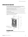
Air filter removal and replacement.................................................................. 85
Time and items required..................................................................... 85
Removing an air filter.......................................................................... 86
Replacing an air filter.......................................................................... 86
Module filler panel removal and replacement................................................. 86
Removing a filler panel........................................................................86
Replacing a filler panel........................................................................87
Chassis ID card removal and replacement..................................................... 87
SFP transceiver removal and replacement..................................................... 88
Time and items required..................................................................... 88
Removing a transceiver...................................................................... 89
Replacing a transceiver.......................................................................90
QSFP transceiver removal and replacement.................................................. 90
Removing a QSFP transceiver............................................................90
Replacing a QSFP transceiver............................................................91
Cable routing table.......................................................................................... 91
Brocade VDX 8770 Switch Technical Specifications.................................................................95
Regulatory Statements..........................................................................................................105
BSMI statement (Taiwan)..............................................................................105
Canadian requirements.................................................................................105
CE Statement................................................................................................105
China ROHS................................................................................................. 106
FCC warning (US only)................................................................................. 106
KCC statement (Republic of Korea)..............................................................106
VCCI statement.............................................................................................106
Cautions and Danger Notices................................................................................................107
Cautions........................................................................................................ 107
Danger Notices............................................................................................. 112
Brocade VDX 8770-8 Hardware Installation Guide
53-1002564-07
5
6
Brocade VDX 8770-8 Hardware Installation Guide
53-1002564-07
Preface
● Document conventions......................................................................................................7
● Brocade resources............................................................................................................ 9
● Contacting Brocade Technical Support.............................................................................9
● Document feedback........................................................................................................ 10
Document conventions
The document conventions describe text formatting conventions, command syntax conventions, and
important notice formats used in Brocade technical documentation.
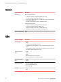
Text formatting conventions
Text formatting conventions such as boldface, italic, or Courier font may be used in the flow of the text
to highlight specific words or phrases.
Format
Description
bold text
Identifies command names
Identifies keywords and operands
Identifies the names of user-manipulated GUI elements
Identifies text to enter at the GUI
italic text
Identifies emphasis
Identifies variables
Identifies document titles
Courier font
Identifies CLI output
Identifies command syntax examples
Command syntax conventions
Bold and italic text identify command syntax components. Delimiters and operators define groupings of
parameters and their logical relationships.
Convention
Description
bold text
Identifies command names, keywords, and command options.
italic text
Identifies a variable.
value
In Fibre Channel products, a fixed value provided as input to a command
option is printed in plain text, for example, --show WWN.
Brocade VDX 8770-8 Hardware Installation Guide
53-1002564-07
7
Notes, cautions, and warnings
Convention
Description
[]
Syntax components displayed within square brackets are optional.
Default responses to system prompts are enclosed in square brackets.
{x|y|z}
A choice of required parameters is enclosed in curly brackets separated by
vertical bars. You must select one of the options.
In Fibre Channel products, square brackets may be used instead for this
purpose.
x|y
A vertical bar separates mutually exclusive elements.
<>
Nonprinting characters, for example, passwords, are enclosed in angle
brackets.
...
Repeat the previous element, for example, member[member...].
\
Indicates a “soft” line break in command examples. If a backslash separates
two lines of a command input, enter the entire command at the prompt without
the backslash.
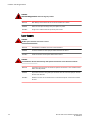
Notes, cautions, and warnings
Notes, cautions, and warning statements may be used in this document. They are listed in the order of
increasing severity of potential hazards.
NOTE
A Note provides a tip, guidance, or advice, emphasizes important information, or provides a reference
to related information.
ATTENTION
An Attention statement indicates a stronger note, for example, to alert you when traffic might be
interrupted or the device might reboot.
CAUTION
A Caution statement alerts you to situations that can be potentially hazardous to you or cause
damage to hardware, firmware, software, or data.
DANGER
A Danger statement indicates conditions or situations that can be potentially lethal or
extremely hazardous to you. Safety labels are also attached directly to products to warn of
these conditions or situations.
8
Brocade VDX 8770-8 Hardware Installation Guide
53-1002564-07
Brocade resources
Brocade resources
Visit the Brocade website to locate related documentation for your product and additional Brocade
resources.
You can download additional publications supporting your product at www.brocade.com. Select the
Brocade Products tab to locate your product, then click the Brocade product name or image to open the
individual product page. The user manuals are available in the resources module at the bottom of the
page under the Documentation category.
To get up-to-the-minute information on Brocade products and resources, go to MyBrocade. You can
register at no cost to obtain a user ID and password.
Release notes are available on MyBrocade under Product Downloads.
White papers, online demonstrations, and data sheets are available through the Brocade website.
Contacting Brocade Technical Support
As a Brocade customer, you can contact Brocade Technical Support 24x7 online, by telephone, or by email. Brocade OEM customers contact their OEM/Solutions provider.
Brocade customers
For product support information and the latest information on contacting the Technical Assistance
Center, go to http://www.brocade.com/services-support/index.html.
If you have purchased Brocade product support directly from Brocade, use one of the following methods
to contact the Brocade Technical Assistance Center 24x7.
Online
Telephone
E-mail
Preferred method of contact for nonurgent issues:
Required for Sev 1-Critical and Sev
2-High issues:
[email protected]
• My Cases through MyBrocade
•
Continental US: 1-800-752-8061
• Software downloads and licensing •
tools
Europe, Middle East, Africa, and
Asia Pacific: +800-AT FIBREE
(+800 28 34 27 33)
• Knowledge Base
•
For areas unable to access toll
free number: +1-408-333-6061
•
Toll-free numbers are available in
many countries.
Please include:
•
Problem summary
•
Serial number
•
Installation details
•
Environment description
Brocade OEM customers
If you have purchased Brocade product support from a Brocade OEM/Solution Provider, contact your
OEM/Solution Provider for all of your product support needs.
• OEM/Solution Providers are trained and certified by Brocade to support Brocade® products.
• Brocade provides backline support for issues that cannot be resolved by the OEM/Solution Provider.
Brocade VDX 8770-8 Hardware Installation Guide
53-1002564-07
9
Document feedback
• Brocade Supplemental Support augments your existing OEM support contract, providing direct
access to Brocade expertise. For more information, contact Brocade or your OEM.
• For questions regarding service levels and response times, contact your OEM/Solution Provider.
Document feedback
To send feedback and report errors in the documentation you can use the feedback form posted with
the document or you can e-mail the documentation team.
Quality is our first concern at Brocade and we have made every effort to ensure the accuracy and
completeness of this document. However, if you find an error or an omission, or you think that a topic
needs further development, we want to hear from you. You can provide feedback in two ways:
• Through the online feedback form in the HTML documents posted on www.brocade.com.
• By sending your feedback to [email protected].
Provide the publication title, part number, and as much detail as possible, including the topic heading
and page number if applicable, as well as your suggestions for improvement.
10
Brocade VDX 8770-8 Hardware Installation Guide
53-1002564-07
Product Overview
● Product features..............................................................................................................11
● Hardware components.................................................................................................... 12
● Supported Line cards...................................................................................................... 15
● High availability............................................................................................................... 18
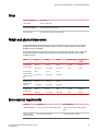
Product features
The Brocade device described in this guide is part of the Brocade Next Generation Data Center
Networks product line, a highly robust class of network switching platforms that combines breakthrough
performance, scalability, and energy efficiency with long-term investment. These chassis are designed
to address the data growth and application demands of evolving enterprise data centers.
The Brocade device features the Brocade CloudPlex™ architecture, a fabric-based Ethernet technology
that can present virtual desktops over a global network that integrates both static and cloud-based
resources.
The Brocade device requires Brocade Network Operating System (Network OS) v3.0.0 or later. For
details about Network OS, refer to the Network OS Administration Guide.
A key, licensable feature of the Brocade device is Brocade VCS ® technology, which includes virtual
cluster switching, a new set of technologies that allows users to create flatter, virtualized, and highly
available data center networks. VCS fabrics are scalable, permitting users to expand at their own pace,
and simplified, allowing users to manage the fabric as a single entity. VCS fabrics are convergencecapable, supporting technologies such as iSCSI and network access server (NAS) as well as Fibre
Channel over Ethernet (FCoE) (licensable) for storage.
Key features of the Brocade device include:
•
•
•
•
•
•
A variety of external port types and speeds in supported line card modules
Dual, redundant management modules (MMs)
Up to six switch fabric modules (SFMs)
Up to eight redundant, hot-swappable power supplies at 220 VAC or -48 VDC
Up to four hot-swappable fan modules
Serial (console), Ethernet, and USB connections for management modules
NOTE
USB support is for Brocade-branded USB devices only
•
•
•
•
•
•
•
•
Support for short wavelength (SX) and long wavelength (LX) 1 Gbps SFP transceivers
Support for (short range (SR) and (long range (LR) 10 Gbps SFP+ transceivers
Support for 40 Gbps QSFP transceivers
Support for 100 Gbps CFP2 (SR10 and LR4) optical transceivers
Support for 10 GbE SFP+ optical transceivers
Support for 1 GbE optical and copper SFP transceivers
Support for SFP transceivers that enable you to adapt an SFP slot to a copper GbE interface.
Support for fixed 10Base-T (RJ-45) copper transceivers
Brocade VDX 8770-8 Hardware Installation Guide
53-1002564-07
11
Hardware components
• Support for active twinaxial (twinax) cable at 1, 3, and 5 meters for 10 GbE ports
• Support for twinax and optical breakout cables for 40 GbE ports
NOTE
Support for the preceding optics depends on the installed line card. For details, refer to the "hardware
components" and "line cards" sections of this chapter.
•
•
•
•
•
NEBS-compliant chassis (certification in process)
Support for in-band management
15U form factor for chassis
Support for Brocade trunking through the 48x10 GbE and 48x10G-T line card modules
Support for Fibre Channel over Ethernet (FCoE)
Hardware components
The device features a modular and scalable mechanical construction that allows a wide range of
flexibility in installation, fabric design, and maintenance. The minimum chassis configuration is one
management module (MM), one switch fabric module (SFM), and one line card. The chassis can be
mounted with the cables facing the front of the equipment rack and consists of the following
components:
• Eight slots for hot-swappable line cards that can be configured in a single chassis. Depending on
the line cards installed, the following ports are available:
‐
Up to 384 1/10 Gbps ports for the 48x10 GbE line card.
‐
48x10 GbE line cards support 10 GbE SFP+ and 1 GbE SFP optical transceivers, as well
as 1 GbE copper SFP transceivers. They also support direct-attach 10 GbE copper
twinaxial (twinax) cables at 1, 3, or 5 meters.
Up to 384 1 Gigabit Ethernet (GbE) ports for the 48x1 GbE line card.
‐
48x1 GbE line cards support 1 GbE SFP optical and copper transceivers.
Up to 96 40 Gigabit Ethernet (GbE) ports for the 12x40 GbE line card. Up to 384 10 Gbps
ports are supported in QSFP breakout mode.
‐
12x40 GbE line cards support 40 GbE QSFP optical transceivers.
Up to 48 100 Gigabit Ethernet (GbE) ports for the 6x100 GbE line card.
‐
The 6x100 GbE line cards ship with two base 100 Gigabit ports enabled, but can be
upgraded to enable six ports through the 100G Port Upgrade license. This upgrade license
is supported by Network OS 5.0.0 and later. Ports support 100 GbE CFP2 (SR10 and LR4)
optical transceivers.
Up to 384 1/10 Gigabit Base-T Ethernet ports for the 48x10G-T line card.
‐
48x10G-T line cards support fixed 10 GbE Base-T (RJ-45) copper transceivers.
Up to 216 40 Gigabit Ethernet (GbE) ports for the 27x40 GbE line card. Up to 576 10
Gigabit ports are supported in QSFP breakout mode.
27x40 GbE line cards support 40 GbE QSFP optical transceivers.
• Two slots for management modules:
‐
‐
A single active management module can control all ports in the chassis.
The standby management module takes control of the device if the active management
module fails.
• Six slots for switch fabric modules that interconnect all line cards.
12
Brocade VDX 8770-8 Hardware Installation Guide
53-1002564-07
Port side view
• Modular, hot-swappable field-replaceable units (FRUs):
‐
‐
‐
‐
‐
‐
‐
‐
48x10 GbE line card
48x1 GbE line card
12x40 GbE line card
6x100 GbE line card
48x10G-T line card
27x40 GbE line card
Four fan assemblies
Up to eight 3000W power supplies, 200-240 VAC auto-sensing or -48 VDC (each power
supply connection should be separately fused)
• Cable management comb
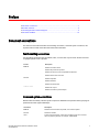
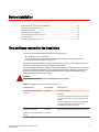
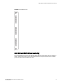
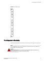
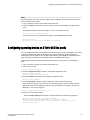
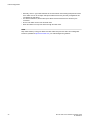
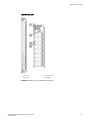
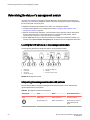
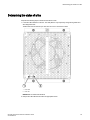
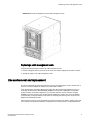
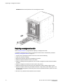
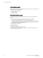
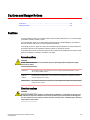
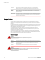
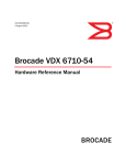
Port side view
NOTE
Airflow in the Brocade device is from the port side to the rear (fan side) of the chassis.
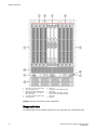
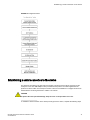
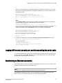
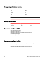
The following figure displays a sample configuration of the port side of the Brocade device.
Brocade VDX 8770-8 Hardware Installation Guide
53-1002564-07
13
Nonport side view
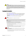
1
2
3
4
5
Line cards L1 through L4 (left to right)
Cable management comb
Switch fabric modules S1 through S6
(odd numbers above, even numbers
below, left to right)
Line cards L5 through L8 (left to right)
Mounting flanges
6
7
8
9
Intake vent
Management modules MM1 and MM2
(left to right)
Power supplies 1 through 8 (1 through
4 above, left to right, 5 through 8 below,
left to right)
ESD jack
FIGURE 1 Port side of the device (sample configuration)
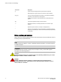
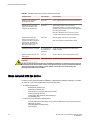
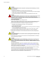
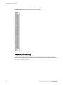
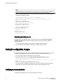
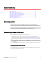
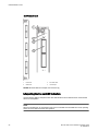
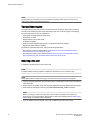
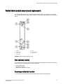
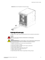
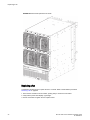
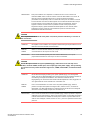
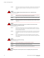
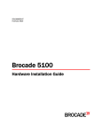
Nonport side view
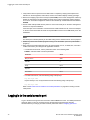
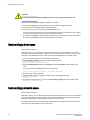
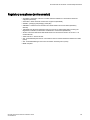
The following figure shows a sample configuration of the nonport side view of the Brocade device.
14
Brocade VDX 8770-8 Hardware Installation Guide
53-1002564-07
Supported Line cards
1
2
Fan assemblies 1 and 2 (left to right)
Fan assemblies 3 and 4 (left to right)
3
4
Power supply exhaust vent
Ground lug
FIGURE 2 Nonport side of the Brocade device (sample configuration)
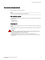
Supported Line cards
The following table summarizes the line cards that are available for the device.
Brocade VDX 8770-8 Hardware Installation Guide
53-1002564-07
15
Breakout mode
TABLE 1 Supported line cards
Line card
Description
12x40 GbE
12 40 Gbps QSFP Ethernet ports.
48x10 GbE
48 1/10 Gbps Ethernet ports.
48x1 GbE
48 1 Gbps Ethernet ports.
6x100 GbE
Two or six 100 Gbps Ethernet ports depending on licensing.
48x10G-T
48 1/10 Gbps Base-T Ethernet ports
27x40 GbE
27 40 Gbps QSFP Ethernet ports
Breakout mode
Quad SFP (QSFP) 40 Gbps ports on 12x40 GbE and 27x40 GbE line cards can be configured in
breakout mode to create four separate 10 Gbps interfaces. You can administer and operate these
interfaces as any other SFP port. Special breakout cables provide a connection to the 40 Gbps QSFP
port and to four 10 Gbps SFP ports on another device. Twinax active copper cables at 1, 3, and 5
meters and fiber-optic breakout cables are supported.
NOTE
While 40 GbE ports are in breakout mode, port status (individual or as a group) cannot be determined
from the port LED state color.
For more information on configuring breakout mode, refer to the Network OS Administrator’s Guide.
Trunking
Network OS supports Brocade trunks (hardware-based link aggregation groups, or LAGs). These
trunks are dynamically formed between two adjacent devices with connected interswitch link (ISL)
ports unless trunking is disabled on connecting ports. Traffic is evenly distributed along all links in a
trunk. For more information on Brocade Trunking and enabling and disabling trunking, refer to the
"Configuring Brocade VCS Fabrics" chapter in the Network OS Administrator’s Guide.
Trunking is supported on GbE interface ports of all line cards.
Port groups
Port groups are established for trunking on supported line cards. To successfully form a trunk from line
card ports to another device, select ports from same line card port group and configure each port to
operate at the same speed. Following are trunk and port group specifications for supported line cards:
• For the 48x10 GbE line card, up to 8 ports are allowed per trunk. Select ports from octet port groups
consisting of ports 1-8, 9-16, 17-24, 25-32, 33-40, and 41-48.
• For the 48x10G-T line card, up to 16 ports are allowed per trunk. Select ports from three port
groups consisting of ports 1-16, 17-32, and 33-48.
16
Brocade VDX 8770-8 Hardware Installation Guide
53-1002564-07
Trunking two 40 GbE ports
• For the 12x40 GbE line card, up to two 40GbE ports are allowed per trunk when these ports are
configured in breakout mode to provide 10GbE interfaces. Select ports from six port groups
consisting of 40GbE ports 1-2, 3-4, 5-6, and 7-8, 9-10, and 11-12.
• For the 27x40 GbE line card, 40GbE ports must be configured in breakout mode to provide 10GbE
interfaces for trunking. There are nine port groups consisting of 40GbE ports 1-3, 4-6, 7-9, 10-12,
13-15, 16-18, 19-21, 22-24, and 25-27. The following rules apply to configuring breakout mode and
trunking on ports in these groups:
‐
‐
You must configure a port group in Performance operating mode. Breakout mode is not
supported on ports configured in Density (default) operating mode.
When the port group is in Performance mode, you can only configure the first two ports in
the port group in breakout mode, since the third port in the group is disabled. Hence,
trunking is only supported on the first two ports in the port group.
Trunking two 40 GbE ports
To form an 80 Gbps trunk between two 40 GbE QSFP transceivers on a 40 GbE line card for an ISL
connection, use the following steps:
1. Configure each QSFP interface in breakout mode, as if you were connecting four separate 10GE
transceivers, then reboot the line card.
2. Use a crossover MTP or MPO 40GE (12-strand) OM3/OM4 Fibre to connect the QSFPs to each
other.
For more information on Brocade Trunking and configuring breakout mode, refer to the following:
• "Configuring SFP Breakout Mode" in the Network OS Layer 2 Switching Configuration Guide
• "Brocade Trunks" in the Network OS Administration Guide
27x40 GbE operating modes
The 27x40 GbE line card supports nine port groups of three ports each that you can configure for
Performance or Density operating modes.
• Performance mode - Because the line card is oversubscribed and cannot support the 40 Gbps line
rate on all 27 ports, you can configure Performance mode to achieve 40 Gbps rate for up to 18 ports.
When a port group is configured In Performance mode, the third port in the port group is persistently
disabled, but the remaining two ports operate at up to 40 Gbps to achieve the 80 Gbps maximum
rate for the port group. QSFP breakout mode is only supported on ports configured in Performance
mode.
• Density mode - This is the default mode for all the port groups. In this mode, all the three ports are
enabled in each group, but cannot support the 40 Gbps maximum rate. If this mode is configured on
all port groups, 27 total ports are available for use.
Configure Performance or Density mode for individual port groups using Network OS commands (refer
to the Network OS Command Reference ).
For configuring operation modes, ID numbers are assigned to each port group sequentially from port 1
through 27 as shown in the following table.
TABLE 2 27x40 GbE line card port groups
Port Group ID
Port Numbers
1
1-3
Brocade VDX 8770-8 Hardware Installation Guide
53-1002564-07
17
High availability
TABLE 2 27x40 GbE line card port groups (Continued)
Port Group ID
Port Numbers
2
4-6
3
7-9
4
10-12
5
13-15
6
16-18
7
19-21
8
22-24
9
25-27
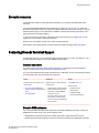
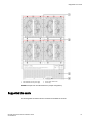
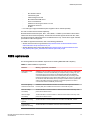
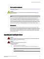
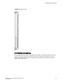
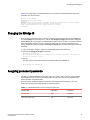
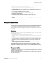
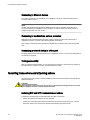
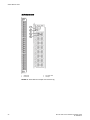
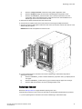
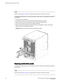
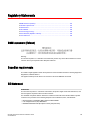
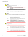
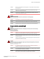
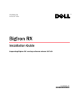
Port groups for configuring operation modes are illustrated in the following figure. If you configure a
port group in Performance mode, the first two ports in a group are enabled for Performance mode. The
third port is disabled as it can only be configured in density mode only. I If you configure the port group
in Density mode, all three ports are enabled for density mode. To identify the port group, use the
format rbridge-id/slot-id/port group-id. For example, 1/3/9 denotes RBridge 1, slot 3, and port-group-id
9.
FIGURE 3 Port groups for configuring Performance and Density modes on 27x40 GbE line card
To configure Performance and Density modes for line card port groups using Network OS commands,
refer to 27x40 GbE operating modes.
High availability
High availability is currently limited to management module configuration synchronization. Failover to
the standby module will occur in case of active module failure, but the standby module will go through
a cold recovery in which all system components are reset. This will disrupt traffic on the chassis. The
reset could take up to eight minutes depending on chassis configuration and traffic load.
18
Brocade VDX 8770-8 Hardware Installation Guide
53-1002564-07
Device Installation
● Time and items required for the installation.................................................................... 19
● Items included with the device........................................................................................ 20
● NEBS requirements........................................................................................................ 21
● Preparing for the installation........................................................................................... 23
● Unpacking and installing the device................................................................................25
● Port numbering................................................................................................................26
● Providing power to the device......................................................................................... 31
Time and items required for the installation
You can set up and install the Brocade device in the following ways:
• As a standalone unit on a flat surface
• In a 19-inch Electronic Industries Association (EIA) rack, using the four-post rack mount kit
• In a two-post telecommunications (Telco) rack
This section describes standalone installtion procedures only. For rack mount installation instructions,
refer to the manual that comes with the separately ordered rack kit.
The following table describes the installation tasks, the estimated time required for each, and the items
required to complete the task based on a fully populated chassis (384 10 GbE ports). Configurations
with fewer ports require less time. These time estimates assume a prepared installation site and
appropriate power and network connectivity.
DANGER
The procedures in this manual are for qualified service personnel.
TABLE 3 Installation tasks, time, and items required
Installation task
Time estimate
Items required
Site preparation and unpacking
the device
30 minutes
#2 Phillips screwdriver
Pallet jack.
Hydraulic lift or assisted lift, able to raise to a minimum
of 140 cm (55 in.), with a minimum capacity of 113 kg
(250 lb).
To know the weight of your device fully populated with
the required port blades, refer to the Technical
Specifications at the end of this guide.
Installing rack mount kit
30 minutes
Mounting and securing the device
in rack
30 minutes
Brocade VDX 8770-8 Hardware Installation Guide
53-1002564-07
Refer to the rack mount kit instructions for the device.
19
Items included with the device
TABLE 3 Installation tasks, time, and items required (Continued)
Installation task
Time estimate
Items required
Installing power cables and
powering on the device
20 minutes
Power cables (provided in the device accessories kit).
Establishing serial connection,
logging on to the device, and
configuring the IP addresses.
20 minutes
Serial cable (provided in the accessory kit).
Workstation computer with a serial (console) port or
terminal server port and a terminal emulator application
(such as HyperTerminal).
Ethernet IP addresses for the device and for both
control processor blade (a total of three addresses).
Installing an Ethernet cable,
opening a Telnet session, and
configuring the device domain ID,
date and time, and additional
system parameters. Verify and
back up the configuration.
20 minutes
Ethernet cabling (optional) for Telnet access.
Installing transceivers as needed
30 - 60 minutes (up
to 30 minutes per
transceiver
Copper and optical transceivers and direct-attach
cables as needed
Attaching cables, cable ties, and
cable guides
2-3 hours
Cables, cable ties, and cable management comb.
Refer to the Network OS Administration Guide.
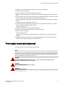
CAUTION
All devices with DC power supplies are intended for installation in restricted access areas only.
A restricted access area is where access can be gained only by service personnel through the
use of a special tool, lock and key, or other means of security, and is controlled by the
authority responsible for the location.
Items included with the device
The basic product (SKUs BR-VDX8770-8-BND-AC or BR-VDX8770-8-BND-DC depending on whether
you order AC or DC power supplies) ships with the following items:
• A chassis, populated with:
‐
Management modules (one)
‐
Switch fabric modules (six)
‐
Filler panels for unoccupied slots for all modules
‐
Power supplies (up to three)
‐
Power supply filler panels for unoccupied bays
‐
Fan modules (four)
• An accessory kit containing the following items:
‐
‐
‐
20
Console cable (RJ-45 serial cable: There is also an adapter that can be used to provide a
DB9-style connector.)
Wrist strap (ESD grounding strap)
Ground lug kit
Brocade VDX 8770-8 Hardware Installation Guide
53-1002564-07
NEBS requirements
‐
SFP extraction tool kit
‐
China RoHS guide
‐
Cable management comb
‐
Brocade-branded USB device
‐
Power cord retainer kit
‐
Hardware for securing the device in a rack
‐
Web pointer document
‐
Air filter
• Line cards (up to eight) and additional power supplies must be ordered separately.
The rack mount kits must be ordered separately.
Brocade-branded transceivers (SFP, SFP+, CFP2, QSFP, or 10Base-T) and cables or direct-attach
cables must also be ordered separately. The Brocade VDX 8770-8 supports SR and LR SFP, SFP+,
and CFP2 transceivers. QSFP transceivers are SR transceivers only. Twinax active copper and fiberoptic breakout cables are supported.
For details on supported transceivers, refer to the following publications:
• Brocade VDX Transceiver Support Matrix at http://www.brocade.com/downloads/documents/
matrices/brocade-vdx-sfp-transceivers-mx.pdf.
• Brocade Ethernet Optics Family data sheet at http://www.brocade.com/downloads/documents/
data_sheets/product_data_sheets/brocade-ethernet-optics-family-ds.pdf.
NEBS requirements
The following table lists the installation requirements for meeting NEBS GR-1089 compliancy.
TABLE 4 NEBS installation requirements
Reference
Warning, requirement, or statement
Intrabuilding or Intraconnection
WARNING: The intra-building copper Ethernet ports of the equipment or subassembly
are suitable for connection to intrabuilding or unexposed wiring or cabling only. The
intra-building ports of the equipment or subassembly MUST NOT be metallically
connected to interfaces that connect to the outside plant (OSP) or its wiring. These
interfaces are designed for use as intra-building interfaces only (Type 2 or Type 4 ports
as described in GR-1089-CORE, Issue 6) and require isolation from the exposed OSP
cabling. The addition of Primary Protectors is not sufficient protection in order to
connect these interfaces metallically to OSP wiring.
First Level Lightning
Criteria AC Power Ports
WARNING: The Brocade device must be connected to external Special Protection
Devices (SPD) when installed and connected to commercial AC power.
Class A2 Voltage
Accessibility
The Brocade device must be located in a restricted access location were only crafts
personnel are allowed access.
Class B Voltage
Accessibility
The Brocade device must be located in a restricted access location were only crafts
personnel are allowed access.
Equipment Grounding
Systems
The Brocade device must be installed and connected to the CBN, IBN, or Ether.
Communication
Equipment Grounding
The Brocade device is suitable for connection to the Central Office.
Brocade VDX 8770-8 Hardware Installation Guide
53-1002564-07
21
Device Installation
TABLE 4 NEBS installation requirements (Continued)
Reference
Warning, requirement, or statement
Bonding of Battery
Return (BR) Input
Terminals
The battery returns of the Brocade device must be connected (DC-I).
Connections
The Brocade device must be grounded via a copper ground conductor.
Connections
All bare grounding connection points to the Brocade device must be cleaned and
coated with an antioxidant solution before connections are made.
Connections
All surfaces on the Brocade device that are un-plated must be brought to a bright finish
and treated with an antioxidant solution before connections are made.
Connections
All non-conductive surfaces on the this device must be removed from all threads and
connection points to ensure electrical continuity.
Connections
The Brocade VDX 8770 utilizes a two-hole compression type, agency-approved
crimped connector with a copper #2 American Wire Gauge (AWG) that utilizes 20 inch
pounds of torque to secure it to the frame and EUT.
Input DC Voltage
The Brocade VDX 8770 is capable of operating at 200-240 V, 50/60 Hz at a maximum
current level of 16.0 A max., or -48VDC, 70.0 A max. per power supply.
Thermal policy
Due to recent changes in the NEBS thermal policy testing procedures, Brocade has
made changes to the thermal policy for the Brocade VDX 8770. These changes include
an additional fan speed (raising the number of fan speeds to 4 from 5) and slightly
altered trigger temperatures. Additional non-user visible RASlog message generation
has also been included with this change to allow for easier debugging and thermal
history recording.
The precise values for temperature and fan RPM are related to the specific hardware
combinations possible in the modular switch. For the sake of brevity, the following table
lists the possible range of values for each heat level.
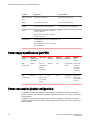
TABLE 5 NEBS thermal policy levels
22
Level
Description
Ambient temperature
Temperature
RPM
1
LOW
up to 25C
up to70C
2500 RPM
2
MED-LOW
up to 25C
from 48C through
80C
3500 RPM
3
MED
up to 39C
from 52C through
86C
5500 RPM
4
HIGH
up to 51C
from 65C through
93C
7350 RPM
5
MAX
up to 58C
from 73C through
99C
9300 RPM
Brocade VDX 8770-8 Hardware Installation Guide
53-1002564-07
Preparing for the installation
CAUTION
For the NEBS-compliant installation of a Brocade device with AC or DC systems, use a ground
wire of at least 2 AWG. The ground wire should have an agency-approved crimped connector
(provided with the device) attached to one end, with the other end attached to building ground.
The connector must be crimped with the proper tool, allowing it to be connected to both ground
screws on the enclosure. Before crimping the ground wire into the provided ground lug, ensure
that the bare copper wire has been cleaned and antioxidant is applied to the bare wire. In
addition, anti-rotation devices or lock washers must be used with all screw connections for the
grounding wire.
Preparing for the installation
Review the following before installing the device:
• Refer to Cautions and Danger Notices on page 107 to review safety precautions and translations.
• Refer to "NEBS requirements on page 21" to ensure compliance with NEBS-GR-1089 standards
• Refer to the Brocade VDX 8770 Switch Technical Specifications on page 95 to ensure power
supply standards are met before installing the chassis and to review the to environmental
requirements.
• Refer to "Preparing for the installation" section to plan for cable management.
DANGER
The procedures in this manual are for qualified service personnel.
NOTE
Brocade strongly recommends that devices be installed in environments that have minimal dust and
airborne contaminants.
The following steps are required to ensure correct installation and operation.
1. Ensure that doorways are wider than 91 cm (36 in.) to accommodate the device.
2. Provide a space that is 15 rack units (15U) high, 61.29 cm (24.09 in.) deep, and 43.74 cm (17.22 in.)
wide. One rack unit is equal to 4.45 cm (1.75 in.).
Plan to install the Brocade device with the port side facing the air-intake aisle. Airflow is from the port
side of the device to the fan side.
Ensure that the rack is balanced and mechanically secured to provide stability in the event of an
earthquake and that the equipment does not exceed the rack’s weight limits.
DANGER
Make sure the rack housing the device is adequately secured to prevent it from becoming
unstable or falling over.
3. Ensure that dedicated electrical branch circuits with the following characteristics are available:
• Up to eight dedicated fused 200-240 VAC, 50-60 Hz feeds or -48 VDC (one per power supply)
• One cable for each power supply
Brocade VDX 8770-8 Hardware Installation Guide
53-1002564-07
23
Device Installation
CAUTION
Use a separate branch circuit for each power cord, which provides redundancy in case one
of the circuits fails.
•
•
•
•
Protected by a circuit breaker in accordance with local electrical codes
Supply circuit, line fusing, and wire size adequate to the electrical rating on the device nameplate
Location close to the device and easily accessible
Grounded outlets installed by a licensed electrician and compatible with the power cords
DANGER
If the installation requires a different power cord than the one supplied with the device, make
sure you use a power cord displaying the mark of the safety agency that defines the
regulations for power cords in your country. The mark is your assurance that the power cord
can be used safely with the device.
4. Plan for cable management before installing the device.
Cables can be managed in a variety of ways, such as by routing cables below the device, to either
side of the device, through cable channels on the sides of the rack, or by using patch panels.
5. Ensure that the following items are available for configuration of the device:
•
•
•
•
Workstation with an installed terminal emulator, such as HyperTerminal
Console (serial) cable (provided)
Ethernet cables (not provided)
Either access to an FTP server or a Brocade USB device for backing up the device configuration
or collecting supportsave output data (optional)
• Transceivers (copper and optical) and compatible cables and direct-attach cables if needed
6. Ensure that the air intake and exhaust vents have a minimum of 5.1 cm (2 in.) of airspace.
7. Ensure that the air temperature on the air intake side is less than 40°C (104°F) during operation.
CAUTION
Do not install the device in an environment where the operating ambient temperature might
exceed 40°C (104°F).
8. Ensure that the power requirements are met. Refer to the Technical Specifications" for a listing of
power requirements per component.
CAUTION
For the DC input circuit to the system (3000W supply), make sure there is a 80 amp circuit
breaker, minimum -48VDC, double pole, on the input lugs to the power supply. The input
wiring for connection to the product should be copper wire, 2 AWG, marked VW-1, and rated
minimum 90o C.
The power requirements for a given device configuration depend on which modules have been
installed in the device. Refer to the Brocade VDX 8770 Switch Technical Specifications on page
95 for information on the power consumption for the modules that can be used in the device along
with the power consumption for the cooling fans.
All numbers for the line cards assume that the card is fully populated with transceivers, including
QSFPs for the 12x40 GbE and 27x40 GbE line cards. All ports are Ethernet.
You can calculate your power requirements by combining the power demands for the various
modules and fan units in your configuration. While you may use fewer ports in a given line card, it is
always safer to use the power requirement of a fully populated card.
24
Brocade VDX 8770-8 Hardware Installation Guide
53-1002564-07
Environmental requirements
Environmental requirements
Ensure that the environmental requirements are met. Refer to the Brocade VDX 8770 Switch Technical
Specifications on page 95.
CAUTION
Do not install the device in an environment where the operating ambient temperature might
exceed 40°C (104°F).
NOTE
The 0° to 40°C (32° to 104°F) range applies to the ambient air temperature at the air intake vents on the
port side of the device.The temperature inside the chassis can reach up to 90°C (194°F) for some
modules during operation. Brocade recommends that the internal temperature not exceed 75°C
(167°F). Cooling policy is based on a combination of ambient temperature and measured temperature
on the modules. Various combinations will result in an increase in fan speed to create more cooling in
the device. If a component approaches a critical temperature that will trigger a module shutdown, there
will be a WARNING message in the RASlog, followed by a CRITICAL message saying that the module
will shut down in two minutes.Use the show environment command to view temperature status.
Chassis slots
Chassis slots are coded and numbered to differentiate between management module slots, switch
fabric module slots, and line card slots. Management modules (MMs) must be installed only in slots M1
and M2. switch fabric modules (SFMs) must be installed only in slots S1 through S6. There must be at
least one switch fabric module installed in either slot S3 or slot S4. The line card slots, L1 through L8,
can be filled with any supported line cards. Unused slots must be filled with the correct filler panels to
maintain adequate cooling.
Unpacking and installing the device
DANGER
A fully populated Brocade device weighs between 86.18 kg (190 lb) and 165.56 kg (365 lb) and
requires a hydraulic or assisted lift to install it.
DANGER
Use safe lifting practices when moving the product.
1. Unpack the device.
a)
b)
Cut the bands that encircle the packaging.
Slide the upper portion of the cardboard shipping box up off the pallet and shipping tray.
NOTE
The product packaging incorporates a wood pallet and brackets. The device sits on top of a
corrugated cardboard shipping tray.
Brocade VDX 8770-8 Hardware Installation Guide
53-1002564-07
25
Port numbering
c)
d)
Save the packing materials in the event you need to return the product.
Leave the device on top of the shipping tray and pallet if the device must be transported to
the installation location.
2. Use a pallet jack or other assisted lift to transport the device to the installation area.
3. Using the rack mount instructions, install the rack components in the rack and mounting flanges on
the device. The rack mount kit and instructions are shipped separately from the device.
4. Remove the accessory kit (cardboard box), packing foam, and anti-static plastic from the device
and set them aside.
5. Remove the foam inserts around the base of the device.
6. Use a lift to raise the device to the correct level. If installing the device in a rack, follow the
instructions provided by the rack kit manufacturer.
7. If applicable, lock the wheels of the lift.
8. Ensure that the device is oriented so that the port side (front) has access to intake air.
9. Gently slide the device onto the final installation surface, ensuring that it remains supported during
the transfer.
10.Before you apply power to the device, you can install the management module, switch fabric
module, and line card modules as well as power supplies to speed up your installation.
Port numbering
Use the illustrations provided to understand the port numbering for each line card supported on the
device.
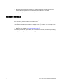
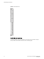
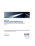
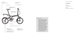
12x40 GbE port numbering
The following illustration shows the 12x40 GbE line card modules. Ports are numbered 1 through 12
from top to bottom when installed in the device.
26
Brocade VDX 8770-8 Hardware Installation Guide
53-1002564-07
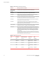
48x1 GbE and 48x10 GbE port numbering
FIGURE 4 12x40 GbE line card
48x1 GbE and 48x10 GbE port numbering
The following illustration shows the 48x1 GbE and 48x10 GbE line card modules. Ports are numbered 1
through 48, from top to bottom, with the odd-numbered ports on the right row and the even-numbered
ports on the left row when installed in the device.
Brocade VDX 8770-8 Hardware Installation Guide
53-1002564-07
27
48x10G-T port numbering
FIGURE 5 48x10 GbE line card (48x1 GbE line card is similar)
48x10G-T port numbering
The following illustration shows the 48x10G-T line card modules. Ports are numbered 1 through 48,
from top to bottom, with the odd-numbered ports on the right row and the even-numbered ports on the
left row when installed in the device.
28
Brocade VDX 8770-8 Hardware Installation Guide
53-1002564-07
27x40 GbE port numbering
FIGURE 6 48x10G-T line card
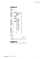
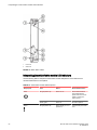
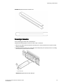
27x40 GbE port numbering
The following illustration shows the 27x40 GbE line card modules. In the dual-port section, the top row
of ports is numbered 1 through 9 and the lower row of ports is numbered 19 through 27, from top to
bottom, when installed on the device. The single ports on the bottom of the device are numbered 10
through 18 from top to bottom.
Brocade VDX 8770-8 Hardware Installation Guide
53-1002564-07
29
6x100 GbE port numbering
FIGURE 7 27x40 GbE line card
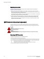
6x100 GbE port numbering
The following illustration shows the 6x100 GbE line card modules. Ports are numbered 1 through 6,
from top to bottom, when installed in the device. Refer to the following figure.
30
Brocade VDX 8770-8 Hardware Installation Guide
53-1002564-07
Providing power to the device
FIGURE 8 6x100 GbE line card
Providing power to the device
Complete the following steps to provide power to the chassis. Each power supply has one power cord.
NOTE
Use the supplied power cords. Ensure the facility power receptacle is the correct type, supplies the
required voltage, and is properly grounded.
DANGER
Make sure that the power source circuits are properly grounded, then use the power cord
supplied with the device to connect it to the power source.
Brocade VDX 8770-8 Hardware Installation Guide
53-1002564-07
31
Connecting an AC power cord
Connecting an AC power cord
1. Plug the power cord into the power supply.
2. Route the cable so it will be out of the way when connected to the power source.
3. Plug the other end of the cable into the power source.
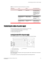
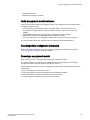
Connecting a DC power cord
1. Use a #1 Phillips screwdriver to remove the screw that secures the safety cover over the power lugs
and remove the safety cover.
2. Use a #2 Phillips screwdriver to unscrew the power lugs.
3. Obtain heat shrink tubing with the following specifications to install on the #2 AWG power supply
input wire:
•
•
•
•
•
•
•
Inside diameter: 1.27 cm (.5 in.)
Minimum 2:1/50% shrink ratio
Nominal Rec. Wall Thickness: 30480 mm (.012 in.) minimum
Dielectric strength: 800V/mil
Tensile strength: greater than or equal to 5000 psi
Operating temperature: -40°C to +150°C (-40°F to 302°F) minimum
RoHS compliant
4. Cut off a 5.08 cm (2 in) lengths for each #2 AWG power supply wire.
5. Slide the tubing over the #2 AWG power supply wire.
6. Crimp the #2 AWG power supply wire into the power lug.
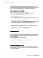
7. Slide the tubing over the lug to the brown strip closest to the lug holes.
8. Apply heat to shrink the tubing over the lug and wire insulation.
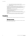
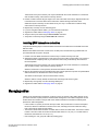
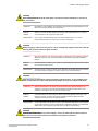
Installed tubing and lugs on power supply wire should conform to the following illustration.
1
2
Heatshrink tubing
Power lug
FIGURE 9 Heat shrink tubing and lug on DC power supply cable
9. Connect the power lugs to the power supply unit.
Connect the -48V wire to the negative terminal and the 0V wire to the positive terminal.
NOTE
The DC return must be isolated from the chassis ground (DC-I) when making connections to the
power supply.
32
Brocade VDX 8770-8 Hardware Installation Guide
53-1002564-07
Device Installation
10.Replace the safety cover.
11.Plug the other end of the cable into the power source.
NOTE
Do not connect the device to the network until the IP addresses are configured.
For information about LED patterns, see Connecting a DC power cord.
Brocade VDX 8770-8 Hardware Installation Guide
53-1002564-07
33
Connecting a DC power cord
34
Brocade VDX 8770-8 Hardware Installation Guide
53-1002564-07
Initial Configuration
● Preparing to configure the device................................................................................... 35
● Establishing a serial connection to the device................................................................ 37
● Logging in to the serial console port............................................................................... 38
● Changing the RBridge ID................................................................................................ 39
● Assigning permanent passwords.................................................................................... 39
● Configuring the IP addresses..........................................................................................40
● Logging off the serial console port and disconnecting the serial cable........................... 41
● Establishing an Ethernet connection...............................................................................41
● Customizing a host name................................................................................................42
● Customizing a chassis name.......................................................................................... 42
● Setting the date and time................................................................................................ 43
● Configuring operating modes on 27x40 GbE line cards..................................................45
● Saving the configuration changes................................................................................... 46
● Verifying correct operation.............................................................................................. 46
● Backing up the configuration...........................................................................................47
● Connecting network devices........................................................................................... 47
● Installing transceivers and attaching cables....................................................................48
● Managing cables............................................................................................................. 49
Preparing to configure the device
The device must be configured before it is connected to the fabric, and all of the configuration
commands must be entered through the active management module. The basic device configuration
includes the following parameters:
•
•
•
•
RBridge ID, if you are going to have more than one device in a fabric.
IP address and gateway address for the device
IP addresses, host names, and gateway addresses for one or two management modules, as needed
Host name
You also need to change passwords from their default values and set the time and date, either by the
way of NTP or manually.
The configuration information is mirrored to the standby management module, if you have installed one,
which allows the current configuration to remain available even if the active management module fails.
The configuration information is stored in the CID cards and the flash memory of the management
modules. The configuration can be backed up to a workstation (uploaded) and then downloaded to the
active management module if necessary.
The device boots up in VCS™ fabric cluster mode and will attempt to form ISLs with connected VCSenabled devices,. If the chassis is not connected to another device, it forms a "single node VCS fabric."
This means that the chassis operates as a standalone system, but the operational mode is always VCSenabled.The device does not support standalone mode.
Brocade VDX 8770-8 Hardware Installation Guide
53-1002564-07
35
Configuration tasks
Fabric cluster mode is defined as a fabric in which the data path for nodes is distributed each member
in the fabric, but the configuration path is not distributed. Each node keeps its configuration database
independently. Fabric cluster mode has three major characteristics:
• The fabric is self-forming. When two or more VCS-enabled devices with unique RBridge IDs are
connected to form a VCS fabric, the fabric is automatically created and the devices discover the
common fabric configuration.
• The fabric is masterless. No single device stores configuration information or controls fabric
operations. Any device can fail or be removed without causing disruptive fabric downtime or
delayed traffic.
• The fabric is aware of all members, devices, and Virtual Machines (VMs). Automatic Migration of
Port Profiles (AMPP) supports VM migration to another physical server. If the VM moves, it is
automatically reconnected to all of its original resources.
When the device connects with a VCS cluster, negotiation protocols determine which device in the
fabric is the principal switch an makes sure that all domain IDs, and therefore RBridge IDs, are unique.
Once the domain IDs are determined to be unique, they are equated to the RBridge IDs. The device
with the lowest World Wide Name (WWN) becomes the principal switch, primarily for purposes of
determining the uniqueness of the ID of the other devices in the fabric. The WWN is a unique identifier
burned into the device at the factory.
If necessary you can change the VCS ID.for the device using the vcs vcsidvcsid command, where the
vcsid is a value from 1 to 8192. By default, the device VCS ID is 1. Change the VCS ID if you need to
create a new, separate VCS fabric.
In order to retain the changes made during configuration, you must copy the running configuration file
to the startup configuration file using the copy running-config startup-config command. This will
ensure that the device reboots to your preferred configuration.
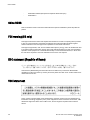
Configuration tasks
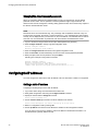
The following figureillustrates the flow of the basic configuration tasks.
36
Brocade VDX 8770-8 Hardware Installation Guide
53-1002564-07
Establishing a serial connection to the device
FIGURE 10 Configuration tasks
Establishing a serial connection to the device
The serial port is located on the port side of the chassis. The device uses an RJ-45 connector for the
serial port. An RJ-45 to DB9 adapter is also provided with the product. The cable supplied with the
product is a rollover cable. The serial port is used to connect to a workstation to configure the device IP
address before connecting the device to a fabric or IP network.
CAUTION
To protect the serial port from damage, keep the cover on the port when not in use.
To establish a serial connection to the serial (console) port on the device, complete the following steps.
Brocade VDX 8770-8 Hardware Installation Guide
53-1002564-07
37
Logging in to the serial console port
1. Verify that the device is powered on and that POST is complete by verifying that all power LED
indicators on the management, switch fabric, and line card modules display a steady green light.
2. Remove the shipping cap from the serial port (labeled I0I0I ) on the active management module. By
default, the management module installed in slot M1 is the active management module unless an
error occurs. The active management module is also indicated by an illuminated blue LED labeled
ACTIVE .
3. Use the serial cable provided with the product to connect the serial port on the active management
module to a computer workstation.
If the serial port on the workstation or terminal device is DB9 instead of RJ-45, remove the adapter
on the end of the serial cable and insert the exposed DB9 connector into the DB9 serial port on the
workstation.
NOTE
The serial port is intended primarily for the initial setting of the IP address and for service purposes.
4. Disable any serial communication programs running on the workstation (such as synchronization
programs).
5. Open a terminal emulator application (such as HyperTerminal on a PC, or TERM, TIP, or Kermit in
a UNIX environment), and configure the application as follows:
• In a Windows environment, use the parameters shown in the following table.
TABLE 6 Windows serial connection parameters
Parameter
Value
Bits per second
9600
Data bits
8
Parity
None
Stop bits
1
Flow control
None
• In a UNIX environment, enter the following string at the prompt:
tip /dev/ttyb -9600
If ttyb is already in use, use ttya instead and enter the following string at the prompt:
tip /dev/ttya -9600
Refer to the Brocade VDX 8770 Switch Technical Specifications on page 95 for a listing of serial
cable pinouts.
Logging in to the serial console port
Log in to the device through the serial connection with the admin user name. The default password is
password. While you are not required to change the password at the initial login, Brocade
recommends that you change your admin and user passwords. Refer to Assigning permanent
38
Brocade VDX 8770-8 Hardware Installation Guide
53-1002564-07
Changing the RBridge ID
passwords on page 39 for more details. Make sure to write down the new passwords and keep this
information in a secure location.
Network OS (8770HOST)
8770HOST console login: admin
Password:
WARNING: The default password of 'admin' and 'user' accounts have not been changed.
Welcome to the Brocade Network Operating System Software
admin connected from 127.0.0.1 using console on 8770HOST
8770HOST#
Changing the RBridge ID
If you are going to have more than one device in a fabric, each device must have a unique RBridge ID.
The default RBridge ID for the device is 1. Use the vcs rbridge-id rbridge-id command to change the
default RBridge ID. You should be in privileged EXEC mode to run the command. If you have made any
other configuration changes you want to persist, be sure to save your running configuration to the
startup configuration before running the vcs rbridge-id rbridge-id command as this command reboots
the device.
1. Log on to the device using the admin account (the default password is password).
2. Enter the vcs rbridge-id rbridge-id command.
device# vcs rbridge-id 2
This operation will change the configuration to default and reboot the switch. Do
you want to continue? [y/n]:y
3. Enter y .
The reply to the command will include a line about the setting of the RBridge ID.
Successfully set rbridge-id.
Assigning permanent passwords
The factory-configured default accounts on the device are "admin," "user," and "root". Use the default
administrative account as shown in the following table to log in to the device for the first time and to
perform the basic configuration tasks.
The root account, disabled by default, is reserved for development and manufacturing. The user
account is read-only and intended primarily for system monitoring.
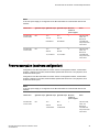
TABLE 7 Default administrative account names and passwords
Account type
Login name
Password
Administrative
admin
password
User account (read-only)
user
password
Brocade VDX 8770-8 Hardware Installation Guide
53-1002564-07
39
Changing the default account passwords
Changing the default account passwords
When you change the default account password after you log in for the first time, only the default
password rule is in effect. The rule specifies a minimum password length of eight characters. For
advanced user and role management, including setting password rules, refer to the Security chapter of
the Network OS Administration Guide.
NOTE
Passwords can be 8 to 40 characters long. They must begin with an alphabetic character. They can
include numeric characters, the period (.), and the underscore (_) only. Passwords are case-sensitive,
and they are not displayed when you enter them on the command line. The available roles are "admin"
and "user". For more information on passwords, refer to the Network OS Administration Guide.
1. Log on to the device using the admin account (the default password is password).
2. Enter configure terminal to change to global configuration mode.
device# configure terminal
Entering configuration mode terminal
3. Enter the configure terminal command to enter global configuration mode.
4. Enter the username command followed by the account name and the password parameter.
5. When prompted, enter the new password. and press Enter .
Following is an example of using these commands:
device# configure terminal
Entering configuration mode terminal
device(config)# username admin password [new-password]
(<WORD>;;User password satisfying password-attributes):********
Configuring the IP addresses
You must configure the device with a static IP address in IPv4 or IPv6 format . DHCP is not supported.
Setting a static IP address
Complete the following steps to set a static IP address.
1. Log in to the device using an account that has the admin role.
2. Enter global configuration mode using the configure terminal command.
3. Specify the chassis with the rbridge-id command.
device(config)# rbridge-id 1
4. Use the chassis virtual-ip command to set the IP address for the chassis.
device(config-rbridge-id 1)# chassis virtual-ip 10.20.236.132/20
5. Return to configuration mode by entering exit .
6. Use the ip address command to set the Ethernet IP address for the management modules.
If you are going to use an IPv4 IP address, enter the IP address in dotted decimal notation. You
should also enter a gateway address as well.
40
Brocade VDX 8770-8 Hardware Installation Guide
53-1002564-07
Logging off the serial console port and disconnecting the serial cable
When you have assigned the IP and gateway addresses to management interface 1/1, you should
also assign IP and gateway addresses to management interface 1/2 if you have installed a second
management module.
device(config)# interface Management 1/1
device(config-Management-1/1)# no ip address dhcp
device(config-Management-1/1)# ip address 10.24.85.81/20
device(config-Management-1/1)# ip gateway-address 10.24.80.1
NOTE
The ip gateway-address command will not be available on the device if the Layer 3 or Advanced
license is installed. In that case, use the following command sequence
switch(config)# rbridge-id 1
switch(config-rbridge-id 1)# ip route 0.0.0.0/0 <default-gateway>
If you are going to use an IPv6 address, enter the network information in semicolon-separated
notation as prompted after the ipv6 address operand. You should also disable DHCP.
device(config)# interface Management 1/1
device(config-Management-1/1)# no ip address dhcp
device(config-Management-1/1)# ipv6 address \
fd00:60:69bc:832:e61f:13ff:fe67:4b94/64
7. Return to privileged EXEC mode by entering exit .
device(config)# exit
device#
8. To display the configuration, use the show running-config interface Management command.
device# show running-config interface Management 1/1
interface Management 1/1
no ip address dhcp
ip address 10.24.85.81/20
ip gateway-address 10.24.80.1
ipv6 address fd00:60:69bc:832:e61f:13ff:fe67:4b94/64
no ipv6 address autoconfig
!
Logging off the serial console port and disconnecting the serial cable
You can use the serial port to monitor error messages through the serial connection. If the serial port is
no longer required, use the logout command to log out of the serial console, remove the serial cable,
and replace the protective plug in the serial port.
Establishing an Ethernet connection
After using a serial connection to configure the IP addresses for the device, you can connect the active
management module to the local area network (LAN).
NOTE
Connecting the management modules to a private network is recommended.
By establishing an Ethernet connection, you can complete the device configuration using a serial
session, Telnet, or management application, such as Brocade Network Advisor.
Brocade VDX 8770-8 Hardware Installation Guide
53-1002564-07
41
Customizing a host name
CAUTION
To protect the Ethernet port from damage, keep the cover on the port when not in use.
Perform the following steps to establish an Ethernet connection.
1. Remove the shipping plug from the Ethernet port on the active management module.
2. Insert one end of an Ethernet cable into the Ethernet port.
3. Connect the other end to an Ethernet 10/100/1000 Base-T LAN.
You can access the device through a remote connection using the command line by way of Telnet
or any of the management tools, such as Brocade Network Advisor.
4. To complete any additional configuration procedures through a Telnet session, log in to the device
by Telnet using the admin login. The default password is password.
Customizing a host name
This procedure is optional.
While still in Telnet, you can change the host name of the device. The host name can be up to 30
characters long; it can include letters, numbers, hyphens, and underscore characters; and must begin
with a letter. The default host name is "sw0." The host name is displayed at the system prompt.
1. Log in to the device using an account that has the admin role.
2. Enter configure terminal to change to global configuration mode.
device# configure terminal
Entering configuration mode terminal
3. Enter switch-attributes followed by the RBridge ID and the host-name operand with the new
name.
If you have changed the RBridge ID, be sure to use that ID.
device(config)# switch-attributes 1 host-name <host-name>
4. Record the new name for reference.
5. Enter exit while in global configuration mode to return to privileged EXEC node.
device(config)# exit
device#
6. To verify the new host name, you can run the show running-config command in EXEC mode.
device# show running-config
Customizing a chassis name
This procedure is optional.
While still in Telnet, you can change the chassis name. The chassis name can be up to 30 characters
long; can include letters, numbers, hyphens, and underscore characters; and must begin with a letter.
The default chassis name is "VDX8770-#" where # is the number of ports.
Brocade recommends that you customize the chassis name for each platform because some of the
system logs refer to the platform by its chassis name.
42
Brocade VDX 8770-8 Hardware Installation Guide
53-1002564-07
Setting the date and time
1. Log in to the device using an account that has the admin role.
2. Enter global configuration mode using the configure terminal command.
3. Enter switch-attributes followed by the RBridge ID and the chassis-name operand with the new
chassis name.
If you have changed the RBridge ID, be sure to use that ID.
device(config)# switch-attributes 1 chassis-name B8770_prime
4. Record the new name for reference.
5. Enter exit while in global configuration mode to return to privileged EXEC mode.
device(config)# exit
device#
6. To verify the new chassis name, you can run the show running-config switch-attributes rbridge-id
command.
device#
show running-config switch-attributes 1
Setting the date and time
The management module maintains the current date and time inside a battery-backed real-time clock
(RTC) circuit. Date and time are used for logging events. The operation of the device does not depend
on the date and time; a Brocade device with an incorrect date and time value functions properly.
Because the date and time are used for logging, error detection, and troubleshooting, you should set
them correctly.
Time zones
You can set the time zone for a device by using the clock timezone command. The time zone setting
has the following characteristics:
• The time zone setting automatically adjusts for Daylight Savings Time.
• Changing the time zone on a device updates the local time zone setup and is reflected in local time
calculations.
• By default, all devices are in the Greenwich Mean Time (GMT) time zone (0,0). If all devices in a
fabric are in one time zone, it is possible for you to keep the time zone setup at the default setting.
• System services that have already started will reflect the time zone changes only after the next
reboot.
• Time zone settings persist across failover for high availability.
• Time zone settings are not affected by Network Time Protocol (NTP) server synchronization.
The following regions are supported: Africa, America, Arctic, Antarctica, Asia, Atlantic, Australia,
Europe, Indian, and Pacific. One of these, along with a city name, establishes the time zone. Refer to
Setting the time zone on page 44.
Time synchronization
To keep the time in your network current, it is recommended that each device has its time synchronized
with at least one external NTP server.
All devices in the fabric maintain the current clock server value in nonvolatile memory. By default, this
value is the local device clock.
Brocade VDX 8770-8 Hardware Installation Guide
53-1002564-07
43
Synchronizing local time using NTP
The ntp server command accepts multiple server addresses in either IPv4 or IPv6 format. When
multiple NTP server addresses are passed, ntp server sets the first obtainable address as the active
NTP server. If there are no reachable time servers, then the local time is the default time.
Synchronizing local time using NTP
Perform the following steps to synchronize the local time using NTP.
1. Log on to the device using the admin account (the default password is password).
2. Enter configure terminal to change to global configuration mode.
device# configure terminal
Entering configuration mode terminal
3. Enter the ntp server"IPv4 address" command, where IPv4 address is the IP address of the first
NTP server in IPv4 format, which the device must be able to access. The IPv4 address variable is
optional. By default, this value is LOCL, which uses the local clock as the clock server.
device(config)# ntp server "132.163.135.131"
To display the NTP server IP address, use the show ntp status rbridge-id rbridge-id command. If
you are in global configuration mode, you must use do before the show command.
device(config)# do show ntp status rbridge-id 1
The request is for the local device unless an RBridge ID is specified. Specify the all parameter to
send the request to all devices in the cluster.
To remove an NTP server, use the no form of the ntp server command.
devic(config)# no ntp server "132.163.135.131"
Setting the time zone
You must perform this procedure on all devices for which the time zone must be set. However, you
only need to set the time zone once on each device, because the value is written to nonvolatile
memory. While not necessary for device operation, setting a time zone is part of ensuring accurate
logging and audit tracking. Time zone changes persist through a reboot without having to save the
current running configuration.
Use the clock timezone command to set the time zone.
1. Log in to the device using an account that has the admin role.
2. Enter the clock timezone region/city command while in privileged EXEC mode.
The following example changes the time zone to US/Pacific Standard Time.
device# clock timezone America/Los_Angeles
Setting the clock (date and time)
The following procedure sets the local clock date and time. An active NTP server, if configured,
automatically updates and overrides the local clock time. Time values are limited to between January
1, 1970 and January 19, 2038.
44
Brocade VDX 8770-8 Hardware Installation Guide
53-1002564-07
Configuring operating modes on 27x40 GbE line cards
NOTE
You should set the clock only if there are no NTP servers configured. Time synchronization from NTP
servers overrides the local clock.
1. Log in to the device using an account that has the admin role.
2. Enter the clock set year-month-dayT hours:minutes:seconds command while in privileged EXEC
mode.
The following example sets the clock to March 17, 2012, 15 minutes past noon.
device# clock set 2012-03-17T12:15:00
If you want to show the clock and time zone settings, use the show clock command.
device# show clock
rbridge-id 1: 2012-03-17 12:15:00 America/Los_Angeles
Configuring operating modes on 27x40 GbE line cards
You can configure Performance or Density mode for the port groups on the 27x40 GbE line card . When
configured in Performance mode, the third port in the group is persistently disabled, allowing the
remaining two ports to operate at up to 40 Gbps. When Density mode (default) is configured, all three
ports in the group are enabled, but will operate at below the 40 Gbps maximum rate.
Use the following steps to set Density and Performance modes on port groups on 27x40 GbE line
cards.
1. Log in to the device using an account that has the admin role.
2. Power off the line card.
device# power-off linecard 3
3. Issue the configure terminal command to enter global configuration mode.
device# configure terminal
Entering configuration mode terminal
4. Enter the hardware command to enter hardware configuration mode.
device(config)# hardware
5. Enter the port-group command to enter configuration mode for a specific port group.
There are nine port groups on the line card. To identify the port group, use the command with the
appropriate values for the rbridge-id/slot-id/port group-id parameters. For example, 1/3/9 denotes
RBridge ID 1, slot 3, and port group 9.
device(config-hardware)# port-group 1/3/9
6. Perform one of the following steps:
• Enter the mode performance command to configure Performance mode for the port group.
device(config-port-group-1/3/9)# mode performance
%Warning: port-group mode performance is a disruptive command.
Please save the running-config to startup-config and a power-cycle for the
changes to take place.
Brocade VDX 8770-8 Hardware Installation Guide
53-1002564-07
45
Displaying operating modes
NOTE
Setting Performance mode shuts down the density-only port in the port group. The configuration is
allowed only when the slot is powered off and takes effect when the slot is powered on.
Enter the no mode performance command to configure Density mode for a port group already
configured for Performance mode.
device(config-port-group-1/3/9)# no mode performance
%Warning: port-group mode performance is a disruptive command.
Please save the running-config to startup-config and a power-cycle for the
changes to take place.
7. Exit port group configuration mode.
device(config-port-group-1/3/9)# exit
8. Exit hardware configuration mode.
device(config-hardware)# exit
9. Exit global configuration mode.
device(config)# exit
device#
10.Power on the line card.
device# power-on linecard 3
Displaying operating modes
To display the current operating mode for a specific port group, use the show running-config
hardware port-group command with the rbridge-id/slot-id/port group-id parameters. Note the
following responses:
• If "mode performance" displays, the port group is enabled in Performance mode.
• If "no mode performance" displays, the port group is enabled in Density mode.
Saving the configuration changes
Complete the following steps to make your changes persistent. This ensures that if you must reboot
the device, the preferences you have set will be in force when the device comes back up.
1. Log in to the device using an account that has the admin role.
2. In privileged EXEC mode, enter the copy running-config startup-config command.
device# copy running-config startup-config
This operation will modify your startup configuration. Do you want to continue?
[Y/N]: Y
3. When the confirmation question appears, answer Y for Yes.
The current running configuration, containing all of your latest changes, is saved to the startup
configuration. The next time the device reboots, all of the changes will remain in force.
Verifying correct operation
Complete the following steps to verify correct operation for the device.
46
Brocade VDX 8770-8 Hardware Installation Guide
53-1002564-07
Backing up the configuration
1. Check the LEDs to verify that all components are functional.
2. If necessary, log in to the device by Telnet, using the admin account.
3. Enter the show chassis command to verify that the device and its components are operating
correctly.
4. Enter the show interface command to show the status of all of the ports in the line cards.
5. Enter the show fabric all command to verify the operation of the device in the fabric.
Backing up the configuration
NOTE
Brocade recommends that you back up the configuration on a regular basis to ensure that a complete
configuration is available for downloading to a replacement management module or chassis. Be sure to
append the date to the end of the target file names to make it clear which are the latest backups.
If you back up your configuration to a USB device, be sure to use a Brocade-branded USB device. The
Brocade USB device comes pre-configured with four directories, /firmware, /config , /support, and /
firmwarekey. Configuration backups are automatically saved in the /config directory.
Alternatively, you can save the configuration files to a remote host using either FTP or SCP. The
destination file argument would be either ftp://username:password@host_ip_address/path/filename or
scp://username:password@host_ip_address/path/filename respectively. Specifying a path is optional.
Be sure to append the date to the target file name.
You can choose to back up the startup configuration or the running configuration or both by using the
copy command with the appropriate parameters. The following procedure backs up the configurations
to a Brocade-branded USB device.
NOTE
Passwords are not saved in the configuration file, and are not uploaded during a configuration upload.
1. Log in to the device using an account that has the admin role.
2. Insert the Brocade-branded USB device into the USB port on the active management module.
3. Enable the USB device by entering the USB on command while in privileged EXEC mode.
• To back up the startup configuration, enter copy startup-config usb://configfile_date.
The date portion of the target file name should be the current date to indicate when the backup
was made .
device# copy startup-config usb://mystartupconfig_06142012
• To back up the running configuration, enter copy running-config usb://configfile_date.
The date portion of the target file name should be the current date to indicate when the backup
was made .
device# copy running-config usb://myrunningconfig_06142012
Connecting network devices
You can connect your chassis to a variety of network devices. Refer to the following topics for some
specific requirements for making these connections.
Brocade VDX 8770-8 Hardware Installation Guide
53-1002564-07
47
Connecting to Ethernet devices
Connecting to Ethernet devices
For copper connections to a 10/100Base-TX or 1000Base-T device or another Brocade device, a
crossover cable is required.
NOTE
The 802.3ab standard (automatic MDI or MDIX detection) calls for automatic negotiation of the
connection between two 1000Base-T ports. Therefore, a crossover cable may not be required; a
straight-through cable may work as well.
Connecting to workstations, servers, or routers
Straight-through unshielded twisted pair (UTP) cabling is required for direct UTP attachment to
workstations, servers, or routers using network interface cards (NICs).
Fiber cabling is required for direct attachment to Gigabit NICs or switches and routers through fiber
ports.
Connecting a network device to a fiber port
For direct attachment from the Brocade device to a Gigabit NIC, switch, or router, fiber cabling with an
LC connector is required.
Testing connectivity
After you install the network cables, you can test network connectivity to other devices by observing
the LEDs related to network connection and performing trace routes.
Installing transceivers and attaching cables
The following two sets of steps cover the installation of transceivers and cables for most SFP and for
QSFP transceivers.
CAUTION
Before plugging a cable into to any port, be sure to discharge the voltage stored on the cable
by touching the electrical contacts to ground surface.
Installing SFP and SFP+ transceivers and cables
Complete the following steps to install optical SFP and SFP+ transceivers.
1. Add the transceivers and cables to the line card ports.
Position one of the optical transceivers so that the key is oriented correctly to the port. Insert the
transceiver into the port until it is firmly seated and the latching mechanism clicks.
48
Brocade VDX 8770-8 Hardware Installation Guide
53-1002564-07
Installing QSFP transceivers and cables
Transceivers are keyed so that they can only be inserted with the correct orientation. If a transceiver
does not slide in easily, ensure that it is correctly oriented.
2. Position a cable so that the key (the ridge on one side of the cable connector) is aligned with the slot
in the transceiver. Insert the cable into the transceiver until the latching mechanism clicks.
Cables are keyed so that they can be inserted in only one way. If a cable does not slide in easily,
ensure that it is correctly oriented.
3. Repeat step 1 and step 2 for the remaining ports.
4. If you are using direct-attach cables, you can insert them at this time.
5. Organize the cables. Refer to Managing cables on page 49
6. Verify the device port status using the show interface command.
7. Verify fabric connectivity using the show fabric all command.
Installing QSFP transceivers and cables
Complete the following steps to install the QSFP transceivers and cables in the 12x40 GbE and 27x40
GbE line cards.
Because each QSFP transceiver consists of four 10 GbE ports, be aware that any problems with one
port could affect all four ports in the quad.
1. Position one of the QSFP transceivers so that the key is oriented correctly to the port.
2. Grasping the edges of the transceiver, insert the it into the port until it is firmly seated. You can feel a
small click when it completely seats. If your transceiver has a bail, pull the bail up until it latches in
the closed position.
Transceivers are keyed so that they can only be inserted with the correct orientation. If a transceiver
does not slide in easily, ensure that it is correctly oriented.
When the transceiver is correctly seated, the status LED will turn solid amber.
3. Remove the protective plug from the QSFP transceiver and the protective cap from the special QSFP
cable and insert it into the transceiver until it is firmly seated.
The cables are also keyed to fit into the transceivers correctly.
When the cable is correctly seated, the status LED will change from amber to green.
4. Repeat step 1 through step 2 for the remaining QSFP ports.
5. Organize the cables. Refer to Managing cables on page 49
Managing cables
Cables can be organized and managed in a variety of ways; for example, using cable channels on the
port sides of the rack or patch panels to minimize cable management. The cable management comb is
located above the modules on the port side of the chassis. Brocade recommends the following best
practices for cable management.
• Leave at least 1 m (3.28 ft.) of slack for each port cable. This provides room to remove and replace
the device, allows for inadvertent movement of the rack, and helps prevent the cables from being
bent to less than the minimum bend radius.
• The minimum bend radius should be no smaller than ten times the cable radius. The minimum radius
to which a 50 micron cable can be bent under full tensile load is 5.1 cm (2 in.). For a cable under no
tensile load, that minimum is 3.0 cm (1.2 in.).
• If ISL trunking is in use, group the cables by trunking group.
Brocade VDX 8770-8 Hardware Installation Guide
53-1002564-07
49
Initial Configuration
• Generally, Velcro ® -type cable restraints are recommended to avoid creating sharp bends or kinks
in the cables. Do not use tie wraps with optical cables because they are easily overtightened and
can damage the optic fibers.
• For easier maintenance, label the fiber-optic cables and record the devices to which they are
connected.
• Do not route cables in front of the air intake vents.
• Route the cables to the top of the device through the cable comb.
NOTE
Keep LEDs visible by routing port cables and other cables away from the LEDs. See "Cabling Best
Practices" (available at http://www.brocade.com ) for cable management guidelines.
50
Brocade VDX 8770-8 Hardware Installation Guide
53-1002564-07
System Monitoring
● Monitoring overview........................................................................................................ 51
● Determining the status of a line card...............................................................................51
● Determining the status of a management module.......................................................... 60
● Determining the status of a switch fabric module............................................................61
● Determining the status of a power supply....................................................................... 63
● Determining the status of a fan....................................................................................... 65
● Determining the status of a CID card.............................................................................. 66
Monitoring overview
The Brocade device is engineered for reliability and requires no routine operational steps or
maintenance. This section provides information about determining the status of each component using
LEDs and CLI commands. Refer to the Network OS Administration Guide for additional information.
There are two commands that can be especially helpful in monitoring the health status of various device
components. These commands are show chassis and the various show environment commands. For
details about these commands, refer to the Network OS Command Reference.
Determining the status of a line card
Use the following procedure to determine the status of a line card.
1. Locate the LEDs on the line card. Refer to the line card illustrations in the following sections.
The LED patterns may temporarily change during POST and other diagnostic tests. For information
about how to interpret the LED patterns, refer to Interpreting the line card LED indicators on page
56.
2. Use the show linecard or show slots command to determine if the line cards are enabled. The line
cards are labeled L1 through L8 in the output. The show linecard command limits the output to the
line card slots only.
3. Use the show interface command to determine the status of the interfaces (ports) on the line card,
Locating the LEDs on the line card
Use the following illustrations to locate the LEDs on the line cards available on the device.Full views
and close-ups are provided for each line card.
Brocade VDX 8770-8 Hardware Installation Guide
53-1002564-07
51
8x10 GbE line card
8x10 GbE line card
1
2
Status LED
Power LED
3
4
Port Status LED
GbE port
FIGURE 11 48x10 GbE line card (full view and close-up)
52
Brocade VDX 8770-8 Hardware Installation Guide
53-1002564-07
12x40 GbE line card
12x40 GbE line card
1
2
Status LED
Power LED
3
4
Port Status LED
GbE port
FIGURE 12 12x40 GbE line card (full view and close-up)
27x40 GbE line card
FIGURE 13 27x40 GbE line card (full view and close-up)
Brocade VDX 8770-8 Hardware Installation Guide
53-1002564-07
53
System Monitoring
1.
2.
3.
4.
54
Status LED
Power LED
3. 40 GbE Port Status LED
40 GbE Port
Brocade VDX 8770-8 Hardware Installation Guide
53-1002564-07
48x10G-T line card
48x10G-T line card
1
2
Power LED
Status LED
3
4
Port Status LED
10 GbE port
FIGURE 14 48x10G-T line card (full view and close-up)
Brocade VDX 8770-8 Hardware Installation Guide
53-1002564-07
55
6x100 GbE line card
6x100 GbE line card
1
2
Power LED
Status LED
3
4
Port Status LED
100 GbE port
FIGURE 15 6x100 GbE line card (full view and close-up)
Interpreting the line card LED indicators
Use the following table to interpret the line card LED indications and to determine the recommended
actions for each pattern.
NOTE
When the 40 GbE ports are in breakout mode on the 27x40 GbE and 12x40 GbE line cards, operating
status cannot be determined from LED operation.
56
Brocade VDX 8770-8 Hardware Installation Guide
53-1002564-07
System Monitoring
TABLE 8 Line card LED descriptions
LED purpose
Color
Status
Recommended action
Power LED
No light (LED is off)
Module is not powered on.
Ensure that the module is
firmly seated and either the
thumbscrew is fully
engaged or the slider is
pushed up and the ejectors
are fully engaged.
Steady green
Module is powered on.
No action required.
No light (LED is off)
Module is operational.
No action required.
No power.
No action required.
Steady amber
Module is faulty or module
is booting up.
If module is not booting up,
ensure that the module is
firmly seated and check the
status by entering the
show slot command. If the
LED remains amber,
consult your Brocade
supplier.
Flashing amber
Module is not seated
correctly.
Pull the module out and
reseat it. If the LED
remains amber, replace the
module.
The pluggable module
(SFP/QSFP/CFP) is not
inserted in the port cage or
the module is inserted, but
no external link is
connected.
Verify that the power LED
is on, check the transceiver
and cable.
Steady green
The port is online but has
no traffic.
No action required.
Flickering green
The port is online with
traffic flowing through the
port.
No action required.
Steady amber
The port is receiving light
but it is not online yet.
Reset the port by issuing a
shutdown and no
shutdown command
sequence on the port.
Slow flashing amber (on 2
seconds, then off 2
seconds)
The port is disabled.
Enable the port by issuing
the no shutdown
command.
Status LED
Power LED steady green.
No light (LED is off)
Power LED is off.
10 GbE Port Status (48x10 No light (LED is off)
GbE line card) or 1 GbE
Port Status (48x1 GbE line
card)
Brocade VDX 8770-8 Hardware Installation Guide
53-1002564-07
57
System Monitoring
TABLE 8 Line card LED descriptions (Continued)
LED purpose
40 GbE QSFP Port Status
(12x40 GbE or 27x40 GbE
line card) in 40 GbE mode
58
Color
Status
Recommended action
Fast flashing amber (on 1/4 The transceiver or port is
second, then off 1/4
faulty.
second)
Change the transceiver or
reset the port by issuing a
shutdown and no
shutdown command
sequence.
Slow flashing green (on 2
seconds, then off 2
seconds)
The port is online but
segmented (either a
loopback cable or
incompatible device
connection).
Consult the Network OS
Software Troubleshooting
Guide.
Medium flashing green (on
1 seconds, then off 1
seconds)
Beaconing (used to identify No action required.
specific ports).
Fast flashing green (on 1/2
second, then off 1/2
second)
Internal loopback
(diagnostic).
In diagnostic mode. Will
return to regular mode
when diagnostic is finished.
No light (LED is off)
There is no QSFP
transceiver installed.
Verify that the power LED
is on, ensure the
transceiver is fully seated
or install the transceiver.
Steady green
The port is online but has
no traffic.
No action required.
Flickering green
The port is online with
traffic flowing through the
port.
No action required.
Steady amber
The port is receiving light
but it is not online yet.
Reset the port by issuing a
shutdown and no
shutdown command
sequence on the port.
Slow flashing amber (on 2
seconds, then off 2
seconds)
The port is disabled.
Enable the port by issuing
the no shutdown
command.
Fast flashing amber (on 1/4 The transceiver or port is
second, then off 1/4
faulty.
second)
Change the transceiver or
reset the port by issuing a
shutdown and no
shutdown command
sequence.
Slow flashing green (on 2
seconds, then off 2
seconds)
The port is online but
segmented (either a
loopback cable or
incompatible device
connection).
Consult the Network OS
Software Troubleshooting
Guide.
Medium flashing green (on
1 seconds, then off 1
seconds)
Beaconing (used to identify No action required.
specific ports).
Brocade VDX 8770-8 Hardware Installation Guide
53-1002564-07
System Monitoring
TABLE 8 Line card LED descriptions (Continued)
LED purpose
10 GbE Port Status
(48x10G-T line card)
100 GbE Port Status
(6x100 GbE line card)
Brocade VDX 8770-8 Hardware Installation Guide
53-1002564-07
Color
Status
Recommended action
Fast flashing green (on 1/2
second, then off 1/2
second)
Internal loopback
(diagnostic).
In diagnostic mode. Will
return to regular mode
when diagnostic is finished.
No light (LED is off)
No power to the Line card.
Verify that the power LED
is on, check the transceiver
and cable.
Steady amber
The port is receiving light
but it is not online yet.
Reset the port by issuing a
shutdown and no
shutdown command
sequence on the port.
Slow flashing amber (on 2
seconds, then off 2
seconds)
The port is disabled.
Enable the port by issuing
the no shutdown
command.
Steady green
The port is online but has
no traffic.
No action required.
Flickering green
The port is online with
traffic flowing through the
port.
No action required.
Medium flashing green (on
1 seconds, then off 1
seconds)
Beaconing (used to identify No action required.
specific ports).
No light (LED is off)
There is no transceiver
Verify that the power LED
installed' or no external link is on, ensure the
connected
transceiver is fully seated
or install the transceiver.
Steady green
The port is online but has
no traffic.
No action required.
Flickering green
The port is online with
traffic flowing through the
port.
No action required.
Medium flashing green (on
1 seconds, then off 1
seconds)
Beaconing (used to identify No action required.
specific ports).
Steady amber
The port is receiving light
but it is not online yet.
Reset the port by issuing a
shutdown and no
shutdown command
sequence on the port.
Slow flashing amber (on 2
seconds, then off 2
seconds)
The port is disabled.
Enable the port by issuing
the no shutdown
command.
59
Determining the status of a management module
Determining the status of a management module
You must have at least one management module (MM) active for the chassis to be functional. For
redundancy, you need two management modules. The active management module is designated by
the blue Active LED on the front panel.
Complete the following steps to determine the status of an management module.
1. Locate the LED indicators on the management module (Locating the LED indicators on the
management module on page 60).
2. Observe and interpret the LED pattern. The LED patterns may temporarily change during POST
and other diagnostic tests. For information about how to interpret the LED patterns, refer to
Interpreting the management module LED patterns on page 60.
3. Use the show mm command to determine whether the management modules are enabled. You
can also use the show interface management 1/1 command to see the configuration information.
Locating the LED indicators on the management module
Use the following illustration to identify the LEDs on the management module.
1
2
3
4
Status LED
Power LED
Active LED
Console port (Serial)
5
6
7
Ethernet port (Mgmt IP)
USB port
Ethernet port (Service IP)
FIGURE 16 Management module
Interpreting the management module LED patterns
Use the following table to interpret the management module LED patterns and to determine the
recommended action for each pattern.
TABLE 9 Management module LED descriptions
60
LED purpose
Color
Status
Recommended action
Power
Steady green
MM is powered on.
No action required.
No light (LED is off)
MM is not powered on.
Ensure that the module is
firmly seated and has
power.
Brocade VDX 8770-8 Hardware Installation Guide
53-1002564-07
Determining the status of a switch fabric module
TABLE 9 Management module LED descriptions (Continued)
LED purpose
Color
Status
Recommended action
Status
No light (LED is off)
MM is either healthy or
does not have power.
Verify that the power LED
is on.
Steady amber
MM requires attention or is If the LED remains amber,
still booting up.
the module is faulty.
Consult your supplier.
Steady blue
Module is the active MM.
No light (LED is off)
Module is booting up,
No action required.
negotiating to be the active
MM, or is the standby MM.
Steady green
Ethernet link speed is
1000 Mbps (1 Gbps).
No action required.
No light (LED is off)
There is no link or link
speed is 10 or 100 Mbps.
No action required.
Blinking green
Ethernet link is healthy and No action required.
traffic is flowing through
port.
No light (LED is off)
No traffic is flowing.
Active
Ethernet management link
(upper left)
Ethernet management link
activity (upper right)
No action required.
No action required.
Determining the status of a switch fabric module
At least one functional switch fabric module (SFM) must be plugged into slots S3 or S4 (the "control
plane slots"). If there are no functional switch fabric module s in either slot during bootup, bootup is
halted with a message indicating that condition.
In an operational chassis, if all switch fabric module s in the control plane slots become faulty or are
removed, then all the line cards will be faulted with a reason code that indicates no availability of a
switch fabric module . An external RASlog message will also be displayed.
Complete the following steps to determine the status of a switch fabric module .
1. Locate the LED indicators on the switch fabric module (refer to Locating the LED indicators on the
switch fabric module on page 61). The LED patterns may temporarily change during POST and
other diagnostic tests. For information about how to interpret the LED patterns, refer to Interpreting
the switch fabric module LED indicators on page 62.
2. Use the show sfm command or the show slots command to see whether the switch fabric module is
enabled.
Locating the LED indicators on the switch fabric module
Use the following illustration to identify the LEDs on the switch fabric module.
Brocade VDX 8770-8 Hardware Installation Guide
53-1002564-07
61
Interpreting the switch fabric module LED indicators
1
2
Power LED
Status LED
FIGURE 17 Switch fabric module
Interpreting the switch fabric module LED indicators
Use the following table to interpret the switch fabric module LED patterns and to determine the
recommended actions for each pattern.
TABLE 10 Switch fabric module LED descriptions
LED purpose
Color
Status
Recommended action
Power
No light (LED is off)
SFM is not on.
Ensure that the SFM is
firmly seated and the
power switch is turned on
(slider is covering the
captive screw).
Steady green
SFM is on.
No action required.
No light (LED is off)
SFM is healthy or is not
powered on.
Verify that the power LED
is on.
Status
62
Brocade VDX 8770-8 Hardware Installation Guide
53-1002564-07
Determining the status of a power supply
TABLE 10 Switch fabric module LED descriptions (Continued)
LED purpose
Color
Status
Recommended action
Steady amber
SFM is faulty.
Ensure that the SFM is
firmly seated and check
the status by entering the
show slot command. If
the LED remains amber,
consult the Brocade
supplier.
Slow flashing amber (on 2
seconds, then off 2
seconds)
SFM is not seated
correctly of is faulty.
Pull the SFM out and
reseat it. If the LED
remains amber, replace
the module.
Fast flashing amber (on
1/2 second, then off 1/2
second)
Environmental range
exceeded.
Check for the out-ofbounds environmental
condition and correct it.
Determining the status of a power supply
Complete the following steps to determine the status of a power supply.
1. Locate the alarm LED labeled ALM on the power supply.
2. Observe and interpret the LED pattern.
3. Verify the power supply status
Locating the alarm LED on the power supply
Use the following illustration to locate the alarm LED labeled ALM on the power supply.
1
2
AC power input LED (AC OK)
DC power output LED (DC OK)
3
4
Alarm LED (ALM)
FIGURE 18 Power supply
Use the following table to interpret the power supply LED patterns and to determine the recommended
action for each pattern.
The LED patterns may temporarily change during POST and other diagnostic tests.
Brocade VDX 8770-8 Hardware Installation Guide
53-1002564-07
63
Verifying the power supply status
The Brocade VDX 8770-8 can have up to eight power supplies. Be sure to check each module.
TABLE 11 Power supply LED descriptions
LED purpose
Color
Status
Recommended action
AC OK
No light (LED is off)
Power supply does not
have incoming AC power.
If using AC power, ensure
that the power supply is
firmly seated, the AC
power source is live, and
the power cable is
connected.
Steady green
Power supply has
incoming AC power.
No action required.
No light (LED is off)
The DC output is not in the Ensure that the power
acceptable range.
supply is firmly seated.
Steady green
The DC output is in the
acceptable range.
No action required.
No light (LED is off)
The power supply has not
failed.
No action required.
Steady amber
The power supply has
failed.
Replace the power supply.
DC OK
ALM
Verifying the power supply status
You can check the power supply status by entering the show environment power command. Use the
following table to interpret the command output. You can also use the show system command.
TABLE 12 Output for show environment power command
Output
Explanation
OK
Power supply is functioning correctly.
absent
Power supply is not present. Could also be improperly seated.
unknown
Unknown power supply unit installed.
predicting failure Power supply is present but predicting failure.
faulty
Power supply is present but faulty (no power cable, power switch turned off, fuse blown, or
other internal error). Could also be improperly seated.
For absent or faulty indications, if the power supply is not improperly seated, contact yor Brocade
supplier to order replacement parts. You may also want to do this if the indication is predicting failure.
64
Brocade VDX 8770-8 Hardware Installation Guide
53-1002564-07
Determining the status of a fan
Determining the status of a fan
Complete the following steps to determine the status of a fan.
1. Locate the LED indicators on the fan. The LED patterns may temporarily change during POST and
other diagnostic tests.
The Brocade VDX 8770-8 has up to four fans. Be sure to check each module.
1
2
Power LED
Fault LED
FIGURE 19 Fan module led indicators
2. Interpret the LED indicators and take the appropriate action.
Brocade VDX 8770-8 Hardware Installation Guide
53-1002564-07
65
Determining the status of a CID card
TABLE 13 Fan LED descriptions
LED purpose
Color
Status
OK
No light (LED is off)
Fan does not have power. Ensure that the fan is
firmly seated and has
power.
Steady green
Fan has power.
No action required.
No light (LED is off)
Fan is either healthy or
does not have power.
Ensure that the fan has
power.
Steady amber
Fan has a failure (full or
partial).
Replace the fan.
Fault
Recommended action
3. Determine the fan status using the show environment fan command. (Alternately, you can use the
show system command. )
TABLE 14 Output for show environment fan command
Output
Explanation
Recommended action
OK
The an is functioning correctly at the displayed speed
(RPM).
No action is required.
absent
A fan is not present, or the fan is improperly seated.
below minimum
A fan is present but rotating too slowly or stopped.
Contact your Brocade
supplier to order
replacement parts.
above maximum
The fan is rotating too quickly.
unknown
An unknown fan unit is installed.
faulty
The fan has exceeded hardware tolerance and has
stopped. In this case, the last known fan speed is
displayed. A faulty indicator could also mean that the
fan is improperly seated.
Determining the status of a CID card
Each CID card has two serial EEPROMS (seeproms). One is the critical seeprom and the other is the
non-critical seeprom. Problems with the critical seeprom cannot be fixed with the CID Recovery Tool.
Only issues with the non-critical seeprom can be addressed.
Regular validation tests are run by the system comparing the CID cards to each other. If the
information is identical, then the chassis is operating correctly. Once a mismatch is detected, an FFDC
message is output to the RASlog. Refer to following table for possible messages.
TABLE 15 Messages that may indicate CID card problems
66
Error message
Issue
[EM-1020]...M1, ERROR ... A problem was found
on one or both CID cards (x), please run the
CIDrecov tool to get more information and
recovery options.
Some kind of error or mismatch has been
detected in the CID card audit.
Brocade VDX 8770-8 Hardware Installation Guide
53-1002564-07
System Monitoring
TABLE 15 Messages that may indicate CID card problems (Continued)
Error message
Issue
[EM-1021], ... M1, INFO, ... A CID card has
been inserted, a CID verification audit will
be run to detect any mismatches or other
problems.
A second CID card is enabled and the CID card
audit will be run. If an error is detected during the
audit, an EM-1020 message is generated.
[EM-1022], ... M1, WARNING, ... A CID card
access problem has been encountered, please
run the CIDrecov tool to get more information
and recovery options.
An error is detected during normal access to the
CID cards; typically, one of the cards is corrupted
or inaccessible.
Brocade VDX 8770-8 Hardware Installation Guide
53-1002564-07
67
Determining the status of a CID card
68
Brocade VDX 8770-8 Hardware Installation Guide
53-1002564-07
Removal and Replacement Procedures
● Introduction..................................................................................................................... 69
● ESD precautions............................................................................................................. 69
● Cable management comb removal and replacement..................................................... 70
● Line card removal and replacement................................................................................71
● Management module removal and replacement.............................................................74
● Switch fabric module removal and replacement............................................................. 77
● Power supply removal and replacement......................................................................... 79
● Fan removal and replacement........................................................................................ 83
● Air filter removal and replacement.................................................................................. 85
● Module filler panel removal and replacement................................................................. 86
● Chassis ID card removal and replacement..................................................................... 87
● SFP transceiver removal and replacement..................................................................... 88
● QSFP transceiver removal and replacement.................................................................. 90
● Cable routing table.......................................................................................................... 91
Introduction
NOTE
Read the Cautions and Danger Notices on page 107 and translations at the end of this manual before
servicing.
The field-replaceable units (FRUs) can be removed from the device and replaced without special tools.
The device can continue operating during many of the FRU replacements if the conditions specified in
the procedures are followed.
The following sections contain FRU removal and replacement procedures.
ESD precautions
The device contains ESD-sensitive FRUs. When working with any Brocade FRU, use correct
electrostatic discharge (ESD) procedures.
• Wear a wrist grounding strap connected to chassis ground (if the device is plugged in) or a bench
ground. Refer to ESD precautions for the location of the ESD jack.
DANGER
For safety reasons, the ESD wrist strap should contain a series 1 megaohm resistor.
• Store ESD-sensitive components in anti-static packaging.
Brocade VDX 8770-8 Hardware Installation Guide
53-1002564-07
69
Cable management comb removal and replacement
CAUTION
Static electricity can damage the chassis and other electronic devices. To avoid damage,
keep static-sensitive devices in their static-protective packages until you are ready to install
them.
Cable management comb removal and replacement
You can can continue to operate the device during the replacement of the cable management comb.
Time and items required
The replacement procedure for the cable management comb takes less than 5 minutes. A #1 Phillips
screwdriver is required.
Removing a cable management comb
Complete the following steps to remove the cable management comb. Refer to the illustration provided
with the procedure.
1. Remove the cables from the cable management comb and rearrange the cables around the comb.
2. Unscrew and save the four (4) screws holding the cable management comb to the chassis. Retain
the screws. Support the cable management comb to prevent it from falling.
3. Remove the cable management comb.
70
Brocade VDX 8770-8 Hardware Installation Guide
53-1002564-07
Replacing a cable management comb
FIGURE 20 Removal and replacement of the cable management comb
Replacing a cable management comb
Complete the following steps to replace the cable management comb.
1. Position and tighten the four (4) screws to secure the new cable management comb to the chassis.
2. Arrange the cables in the cable management comb.
Line card removal and replacement
This section describes the physical procedure for removing and replacing line cards in chassis slots. It
does not cover the management modules or the switch fabric modules.
If are replacing a line card with a different type of line card, after removing the original line card, you
must enter the Network OS no linecard slot_number command while in RBridge ID configuration
mode to clear the current slot configuration. You must also select the new line card type using the
linecard slot_number linecard_type command before installing the new line card. For more detailed
command steps, consult procedures in this section for removing and replacing a line card and in the
Network OS Administration Guide.
Install a new line card only if it is supported by the firmware running in the chassis. Inserting a line card
into a chassis running firmware that does not support the line card may result in unexpected behavior.
Brocade VDX 8770-8 Hardware Installation Guide
53-1002564-07
71
Time and items required
NOTE
Any slot that is not occupied by a line card should be occupied by a filler panel to ensure correct
cooling of the chassis and protection from dust.
Time and items required
The replacement procedure for each line card takes less than 10 minutes. Removing and restoring
transceivers and cables may take longer depending on how many must be changed. The following
items are required for the line card replacement:
•
•
•
•
•
•
Electrostatic discharge (ESD) grounding strap
Workstation computer
Replacement line card or filler panel
#2 Phillips screwdriver
Small form-factor pluggable (SFP or SFP+) or QSFP transceivers (as needed)
Optical and copper cables (as needed)
For details on supported transceivers, refer to the following publications:
• Brocade VDX Transceiver Support Matrix at http://www.brocade.com/downloads/documents/
matrices/brocade-vdx-sfp-transceivers-mx.pdf.
• Brocade Ethernet Optics Family data sheet at http://www.brocade.com/downloads/documents/
data_sheets/product_data_sheets/brocade-ethernet-optics-family-ds.pdf.
Removing a line card
Complete the following steps to remove a line card.
NOTE
If multiple modules are being replaced, complete the replacement for one module at a time.
NOTE
Follow ESD precautions while removing any line card. Refer to ESD precautions on page 69.
1. Check for adequate cable slack. Ensure there is plenty of cable slack to remove a line card without
cable obstruction.
2. Ensure that the part number on the line card being replaced matches the replacement part number.
3. Power down the existing line card using the power-off linecard slot_number command.
NOTE
Before removing any cables from a line card, note the cable order (identify each cable by its
physical port). It is a good practice to keep a table of cable to port mapping. Refer to Cable routing
table on page 91 for a blank cable routing table.
4. If you are replacing the line card with a line card of a different type, follow these steps:
72
Brocade VDX 8770-8 Hardware Installation Guide
53-1002564-07
Replacing a line card
a)
b)
c)
Enter the configure terminal command to enter global configuration mode
Enter the rbridge-id rbridge-idcommand to enter RBridge ID configuration mode.
Enter the no linecard slot_numbercommand. This command removes the line card
configuration and its associated interface configuration from the chassis database so a
different type of line card can be used in the slot.
5. Disconnect all cables and transceivers from the line card.
6. Unscrew the two captive screws at the ends of the line card using the Phillips screwdriver.
7. Open the ejectors by rotating them toward the center of the line card face. Pull the line card out of the
chassis using the ejectors.
FIGURE 21 Removal and replacement of the line card
8. If you are replacing the line card with a line card of a different type, follow these steps before
replacing the line card.
a)
b)
c)
Enter the linecard slot_number command followed by a question mark (?) to display the line
card types.
Enter the linecard slot_number linecard_type command using the proper line card type.
Enter the exit command twice to return to privileged EXEC mode.
Replacing a line card
Review the ESD precautions on page 69 before replacing a line card.
Complete this procedure to insert a new line card. Refer to the illustration provided with the procedure.
1. If you are replacing the line card with a line card of a different type, follow these steps:
Brocade VDX 8770-8 Hardware Installation Guide
53-1002564-07
73
Management module removal and replacement
a)
b)
c)
d)
Make sure that you have cleared the configuration for the original line card from the
chassis database using steps under Removing a line card on page 72.
Enter the linecard slot_number command followed by a question mark (?) to display the
current line card types.
Enter the linecard slot_number linecard_type command using the proper line card type for
the new line card.
Enter the exit command twice to return to privileged EXEC mode.
2. Unpack the new line card and remove it from the anti-static bag.
3. Inspect the line card for damage.
4. Remove the protective covers from the backplane connectors.
5. Orient the line card so that the ports are at the front of the device.
6. Open the ejectors by rotating them toward the center of the line card face and align the flat side of
the line card inside the top and bottom rail guides in the slot. Line cards can be inserted in any of
the slots labeled L1 through L8.
7. Slide the line card all the way into the slot.
8. Close the ejectors by rotating them away from the center of the line card. The levering action of the
ejectors seats the line card in the slot.
9. Tighten the captive screws using the Phillips screwdriver.
10.Check to see if the line card has powered on. If not, power on the line card using the power-on
linecard slot_number command.
Verify that the power LED on the line card is displaying a steady green light. If it does not turn on,
ensure that the line card is firmly seated.
The status LED on the line card will show amber until POST completes for the line card. It should
then turn off. If it remains amber, the line card may not be properly seated in the backplane or the
line card may be faulty.
11.If you have replaced a line card with a line card of a different type, follow these steps:
a)
b)
Save the configuration persistently by issuing the copy running-config startup-config
command after the interface module reaches the online state.
Verify the configuration by issuing the show running-config linecard linecard command.
12.Reinstall the transceivers and cables in the line card or install new transceivers and cables if you
have installed a different type of line card.
13.Group and route the cables through the cable management device.
Management module removal and replacement
This section describes how to remove and replace a management module (MM). Each device can
have one or two management modules. They reside in slots M1 and M2. There must be at least one
management module installed for the chassis to operate.
Time and items required
The replacement procedure for the management module takes approximately 30 minutes. The
following items are required for the management module replacement:
•
•
•
•
74
ESD grounding strap
Workstation computer
Serial cable
IP address of an FTP server for backing up the configuration
Brocade VDX 8770-8 Hardware Installation Guide
53-1002564-07
Faulty management module indicators
• #2 Phillips screwdriver
• Replacement management module
Faulty management module indicators
Confirm that you need to replace the management module. The following events might indicate that a
management module is faulty:
• The status LED on the management module is lit steady amber, or the power LED is not lit.
• The management module does not respond to Telnet commands, or the serial console is not
available.
• The show mm command does not show that the management module is enabled.
• Additional information from the show mm command indicates a problem.
• The clock is inaccurate, or the management module does not boot up or shut down normally.
For more information about error messages, refer to the Network OS Message Reference.
Recording critical configuiration information
Back up the chassis configuration before you replace a management module. Refer to Recording
critical configuiration information for backup information.
Removing a management module
Refer to ESD precautions on page 69 before removing a management module.
The chassis continues to operate while a management module is being replaced if the redundant
management module is active and a failover has already occurred.
Complete the following steps to remove a management module. Refer to the illustration provided with
the procedure.
1. Remove any cables connected to the module.
2. Unscrew the captive screws from both ejectors using the Phillips screwdriver.
3. Rotate both ejectors simultaneously toward the center of the module.
4. Pull the management module out of the chassis by the ejectors.
Brocade VDX 8770-8 Hardware Installation Guide
53-1002564-07
75
Replacing a management module
FIGURE 22 Removal and replacement of the management module
Replacing a management module
Refer to ESD precautions on page 69 before replacing a management module.
Complete the following steps to insert an management module. Refer to the illustration provided in
Removing a management module on page 75.
1. Unpack the new management module and remove it from the anti-static bag.
2. Inspect the module for damage.
3. Remove the protective caps from the backplane connectors.
4. Rotate the ejectors toward the center of the module.
5. Align the module pan with the guides in the slot. The first management module should be installed
in slot M1.
6. Slide the management module into the slot until it is firmly seated.
7. Rotate the ejectors away from the center of the module face until the module is tight in the slot.
8. Tighten the captive screws using the Phillips screwdriver. Verify that the power LED is green. If not,
ensure that the management module has power and is firmly seated and that the ejectors are in the
locked position.
9. Reconnect any cables that were attached to the old module.
76
Brocade VDX 8770-8 Hardware Installation Guide
53-1002564-07
Switch fabric module removal and replacement
Switch fabric module removal and replacement
The Brocade VDX 8770-8 has up to six Switch fabric modules (SFMs). The modules can be installed
only in slots S1 through S6. There must be at least one switch fabric module installed in either slot S3 or
slot S4.
1
2
3
4
Ejectors
Captive screws
Status LED
Power LED
5
6
7
Slider
Power enable pin
Slider screws
FIGURE 23 Switch Fabric Module front view
Time and items required
The replacement procedure for the switch fabric module takes approximately 10 minutes. The following
items are required for the switch fabric module replacement:
• ESD grounding strap
• #2 Phillips screwdriver
• Replacement switch fabric module
Removing a switch fabric module
You can continue to operate the device while a switch fabric module is being replaced.
Brocade VDX 8770-8 Hardware Installation Guide
53-1002564-07
77
Replacing a switch fabric module
NOTE
Review and follow ESD precautions on page 69 before removing a switch fabric module..
Complete the following steps to remove a switch fabric module. Refer to the illustration provided with
the procedure.
1. Unscrew the power enable pin.
2. Loosen the two screws on the slider using the Phillips screwdriver if necessary.
3. Pull out the pin and move the slider all the way up, exposing the captive screw.
4. Unscrew the two captive screws using the Phillips screwdriver.
5. Open the ejectors by rotating them toward the center of the module face. Pull the switch fabric
module out of the chassis using the ejectors.
FIGURE 24 Removal and replacement of the switch fabric module
Replacing a switch fabric module
Complete the following steps to insert the switch fabric module . Refer to the illustration provided with
the procedure.
NOTE
Review and follow ESD precautions on page 69 before removing a switch fabric module..
78
Brocade VDX 8770-8 Hardware Installation Guide
53-1002564-07
Power supply removal and replacement
1. Unpack the new switch fabric module and remove it from the anti-static bag.
2. Inspect the module for damage.
3. Remove the protective caps from the backplane connectors.
4. Unscrew the power enable pin, pull it outward, and move the slider toward the center of the module
face.
5. Open the ejectors on the new switch fabric module by rotating them toward the center of the module
face. Orient the switch fabric module so that the ejectors are toward you.
6. Align the module pan with the guides in the slot. The first switch fabric module should be installed in
slot S3.
7. Push the switch fabric module firmly into the slot.
8. Close the ejectors by rotating them away from the center of the switch fabric module . The levering
action of the ejectors seats the module in the slot.
The Status LED comes on.
9. Tighten the captive screws using the Phillips screwdriver.
10.Pull out the power enable pin and move the slider all the way down.
11.Screw in the power enable pin.
The Power LED comes on.
Tighten the screws on the slider.The Status LED goes out when the switch fabric module is fully
initialized.
12.Pack the faulty switch fabric module in the packaging provided with the new switch fabric module,
and contact your supplier to determine the return procedure.
Power supply removal and replacement
Use this procedure to remove and replace a power supply.
NOTE
Depending on the module configuration of the chassis and the number of power supplies installed, the
device may be able to continue operating during the replacement. Refer to The Technical Specifications
to determine your power requirements. If insufficient power is present, the chassis will start powering
down modules until the power demand can be met.
DANGER
This device might have more than one power cord. To reduce the risk of electric shock,
disconnect all power cords before servicing.
DANGER
Remove both power cords before servicing.
DANGER
Disconnect the power cord from all power sources to completely remove power from the device.
Brocade VDX 8770-8 Hardware Installation Guide
53-1002564-07
79
Time and items required
Time and items required
The replacement procedure for each power supply takes less than 5 minutes. The following items are
required for the power supply replacement:
• New power supply unit or filler panel.
• #1 Phillips screwdriver.
• #2 Phillips screwdriver.
Removing an AC power supply
To remove a power supply, complete the following steps. Refer to the illustration provided with the
procedure.
1. Perform the appropriate following action based on whether the device is operating:
• If the device is not operating during the replacement procedure, go to step 2.
• If the device is operating and will continue to operate during the replacement, check the power
LEDs to verify that the minimum number of power supplies is functioning. Refer to the Technical
Specifications to check your power requirements.
2. Unlatch the power cord retainer clip.
3. Remove the power cord.
4. Loosen the captive screw.
5. Push down on the handle to eject the power supply.
6. Grasp the handle and pull, sliding the power supply from the chassis and supporting the power
supply from beneath as you remove it.
80
Brocade VDX 8770-8 Hardware Installation Guide
53-1002564-07
Replacing an AC power supply
FIGURE 25 Removal and replacement of the power supply
Replacing an AC power supply
To replace a power supply, complete the following steps. Refer to the illustration provided with the
procedure.
DANGER
High Touch Current. Earth connection essential before connecting supply.
CAUTION
If you do not install a module or a power supply in a slot, you must keep the slot filler panel in
place. If you run the chassis with an uncovered slot, the system will overheat.
1. Unpack the new power supply and remove it from the anti-static bag.
2. Inspect the power supply for damage.
3. Ensure that the handle of the replacement power supply is pushed down.
4. Insert the power supply into the slot.
5. Rotate the handle upward to fully seat the power supply.
6. Tighten the captive screw. Replace the power cord.
7. Latch the power cord retainer clip.
8. Verify that the power LED on the power supply displays a steady green light.
Brocade VDX 8770-8 Hardware Installation Guide
53-1002564-07
81
Removing a DC power supply
Removing a DC power supply
To remove a DC power supply, complete the following steps.
1. If the device is operating and will continue to operate during the replacement, check the power
LEDs to verify that the minimum number of power supplies is functioning. Refer to the Technical
Specifications to check your power requirements.
2. Disconnect the power supply from the power source.
3. Use a #1 Phillips screwdriver to remove the screw that secures the safety cover over the power
lugs. Remove the safety cover.
4. Use a #2 Phillips screwdriver to unscrew the power lugs.
5. Loosen the captive screw underneath the latch handle on the power supply faceplate.
6. Push down on the handle to eject the power supply.
7. Grasp the handle and pull, sliding the power supply from the chassis and supporting the power
supply from beneath as you remove it.
Replacing a DC power supply
CAUTION
If you do not install a module or a power supply in a slot, you must keep the slot filler panel in
place. If you run the chassis with an uncovered slot, the system will overheat.
To replace a DC power supply, complete the following steps.
1. Unpack the new power supply and remove it from the anti-static bag.
2. Inspect the power supply for damage.
3. Use a #1 Phillips screwdriver to remove the screw that secures the safety cover over the power
lugs. Remove the safety cover.
4. Ensure that the handle of the replacement power supply is rotated down.
5. Insert the power supply into the slot.
6. Rotate the handle upward to fully seat the power supply.
7. Tighten the captive screw.
8. Reconnect the power lugs to the power supply unit.
Connect the -48V wire to the negative terminal and the 0V wire to the positive terminal.
NOTE
The DC return must be isolated from the device ground (DC-I) when making connections to the
connections to the power supply.
9. Replace the safety cover.
10.Reattach the power cord to the power source.
11.Verify that the power LED on the power supply displays a steady green light.
NOTE
This equipment installation must meet NEC/CEC code requirements. Consult local authorities for
regulations.
82
Brocade VDX 8770-8 Hardware Installation Guide
53-1002564-07
Fan removal and replacement
Fan removal and replacement
Use this procedure to remove and replace a fan.
NOTE
The device can continue operating during the fan replacement
Time and items required
The replacement procedure for each fan takes less than 5 minutes. The following items are required for
the fan replacement:
• Replacement fan
• #2 Phillips screwdriver
Removing a fan
Complete the following steps to remove a fan from the chassis. Refer to the illustration provided with the
procedure.
1. Before removing a fan, verify that the other fans are functioning properly. The power LEDs should be
steady green.
DANGER
Be careful not to accidently insert your fingers into the fan tray while removing it from the
chassis. The fan may still be spinning at a high speed.
2. Use the screwdriver to loosen the four captive screws at the top and bottom of the fan.
3. Grasp the handle and pull, sliding the fan from the chassis and supporting the fan from beneath as
you remove it.
Brocade VDX 8770-8 Hardware Installation Guide
53-1002564-07
83
Replacing a fan
FIGURE 26 Removal and replacement of the fan
Replacing a fan
Complete the following steps to replace the fan in a chassis. Refer to the illustration provided in
Removing a fan on page 83.
1. Orient the fan and slide it into the chassis, pushing firmly to ensure that it is seated.
2. Verify that the power LED displays a green light.
3. Use the screwdriver to tighten the four captive screws.
84
Brocade VDX 8770-8 Hardware Installation Guide
53-1002564-07
Air filter removal and replacement
Air filter removal and replacement
You can remove and replace an air filter when it gets too clogged with dirt and dust to operate
efficiently. You should perform regular physical inspections to determine how often to replace the air
filter. Maintaining clean air filters ensures optimal airflow through the devices.
Based on the traffic and particulate levels of the installation location, the site operator should determine
the appropriate replacement intervals for the air filter.
If the air filter were to become sufficiently blocked, the thermal policy of the device would notify the
administrator of an environmental issue with the system.
If a site-specific interval cannot be determined by the site operator, the filter should be replaced on an
interval of every 3 months.
The filters are single use and non-recyclable. They have a UL fire rating of FLAME RETARDANT, UL
94HF-1 UAF and PPI measurement of 25.
The chassis is shown in a two-post mid-mount rack configuration, but the mounting of the air filter is the
same for any rack mount. Refer to the following illustration.
FIGURE 27 Removal and replacement of the air filter
Time and items required
The replacement procedure for the air filter takes less than 5 minutes. Be sure to have the following
items available:
Brocade VDX 8770-8 Hardware Installation Guide
53-1002564-07
85
Removing an air filter
• New air filter
• A #2 Phillips screwdriver
Removing an air filter
Complete the following steps to remove a front air filter from the chassis.
1. While holding the air filter in place, unscrew the four captive mounting screws using the #2 Phillips
screwdriver.
2. Carefully remove the air filter from the chassis.
To avoid having captured particulates drawn into the chassis, remove the filter in a fashion that
maintains the orientation of the filter relative to the system until the filter is 12 inches away from the
intake.
Replacing an air filter
Complete the following steps to mount the new front air filter on the chassis.
1. Orient the new filter over the four mounting holes using the screws as guides.
Be sure the side marked BOTTOM is on the bottom.
2. Using the #2 Phillips screwdriver, initiate the threads, two turns per screw, until all four are started.
3. Tighten all four screws, one at a time.
Do not overtighten the screws as this will compromise the frame, admitting unfiltered air.
Module filler panel removal and replacement
Each removable module in the chassis (except the fans) has a matching filler panel that must be in
place if no module is installed in a slot. This includes management modules, switch fabric modules,
line cards, and power supplies. There are no filler panels for the fans because all fans must be
installed on the chassis.
CAUTION
If you do not install a module or a power supply in a slot, you must keep the slot filler panel in
place. If you run the chassis with an uncovered slot, the system will overheat.
Removing a filler panel
A filler panel should be removed only when being replaced with a new module or another filler panel.
Any slot that is not occupied by a module should be occupied by a filler panel to ensure proper cooling
of the chassis and protection from dust.
CAUTION
If you do not install a module or a power supply in a slot, you must keep the slot filler panel in
place. If you run the chassis with an uncovered slot, the system will overheat.
Filler panels for the management module and switch fabric module are the same. The filler panel for
the line card slot is similar, though larger. Both the management module and switch fabric module
86
Brocade VDX 8770-8 Hardware Installation Guide
53-1002564-07
Replacing a filler panel
panels and line card panels have two release pins and sliders. The filler panel for the power supply slot
is quite different, having only one release pin and slider.
Complete the following steps to remove a filler panel from the chassis.
1. Pull the release pin or pins out and simultaneously move the slider or sliders.
The entire face of the power supply filler panel is a slider and it moves upward to release the panel.
The sliders for the management module and switch fabric module and line card filler panels move
toward the center of the panel to release it.
2. Pull the filler panel out of the chassis using the release pins.
Replacing a filler panel
Do not leave a slot empty. This will adversely affect cooling of the chassis.
CAUTION
If you do not install a module or a power supply in a slot, you must keep the slot filler panel in
place. If you run the chassis with an uncovered slot, the system will overheat.
1. Orient the filler panel.
The management module and switch fabric module and line card filler panels must be aligned with
the slot guides.
The power supply filler panels simply fit into the slots.
2. Slide the filler panel into the slot until it is firmly seated.
The power supply panel may slide too far into the slot. Insert it only until the facing matches the
facing of the other power supplies or filler panels.
3. Move the sliders and release the release pins.
The release pins should retract completely.
Chassis ID card removal and replacement
Chassis ID (CID) cards cannot be removed or replaced by customers. If you experience a CID card
failure, call Brocade Technical Support.
When an error is detected, you can run the CID Recovery Tool to pinpoint the problem and, in some
cases, fix it. If the problem is determined to be in the critical seeprom portion of the card, no recovery is
possible and you must contact Brocade Technical Support. If however, the problem is in the non-critical
seeprom, it is possible that you can use the recovery tool to fix the problem.
To run the CID Recovery Tool, enter the following command in Privileged EXEC mode.
sw0# cidrecov
If the problem is in the critical seeprom, the output indicates that you should call Brocade Technical
Support. If the problem is in the non-critical seeprom, the output describes the issue and the affected
data and gives you several possible options for action.
For more detail concerning these options, refer to the "Using the Chassis ID (CID) Recovery Tool"
chapter in the Network OS Software Troubleshooting Guide and the "cidrecov" topic in the Network OS
Command Reference.
Brocade VDX 8770-8 Hardware Installation Guide
53-1002564-07
87
SFP transceiver removal and replacement
TABLE 16 Options for the CID Recovery Tool
Condition
Recovery Option
One non-critical seeprom is corrupted.
Tool displays the CID to be recovered and prompts to continue or
abort.
Both non-critical seeproms are corrupted.
Tool displays both CIDs to be recovered with default data and
prompts to continue or abort.
Neither non-critical seeprom is corrupted
but there is a data mismatch.
Tool prompts for the CID to be recovered or to abort.
No corruption or mismatch is found.
Tool displays that there is nothing to be done and then exits on
acknowledgment.
SFP transceiver removal and replacement
Use the following procedure to remove and replace an SFP or SFP+ transceiver.
DANGER
All fiber-optic interfaces use Class 1 lasers.
DANGER
Laser Radiation. Do Not View Directly with Optical Instruments. Class 1M Laser Products.
Time and items required
The replacement procedure for one transceiver takes less than 5 minutes. You should have the
following items available:
• Replacement SFP or SFP+ transceiver
• Optical transceiver extraction tool
Most Brocade devices and backbones come with an optical transceiver extraction tool (Figure 28 ) and
holster. The extraction tool is designed to remove transceivers from modules where the space is
limited.
88
Brocade VDX 8770-8 Hardware Installation Guide
53-1002564-07
Removing a transceiver
FIGURE 28 Optical transceiver extraction tool
Removing a transceiver
For the following procedure refer to the illustration.
Complete the following steps to remove an SFP or SFP+ transceiver.
1. Remove any cables that are inserted into the transceiver. Use the extraction tool to open the cable
latching mechanism.
2. Using the hooked end of the tool, pull the bail (wire handle) away from its pivot point and out, sliding
the transceiver out of the device or module.
1
SFP or SFP+ bail
FIGURE 29 Optical transceiver with bail open
Brocade VDX 8770-8 Hardware Installation Guide
53-1002564-07
89
Replacing a transceiver
Replacing a transceiver
Complete the following steps to replace an SFP or SFP+ transceiver. Refer to the illustration in
Removing a transceiver on page 89.
1. Making sure that the bail (wire handle) is in the unlocked or open position, position the optical
transceiver so that the key is oriented correctly to the port. Insert the transceiver into the port until it
is firmly seated and the latching mechanism clicks.
Transceivers are keyed so that they can only be inserted with the correct orientation. If a transceiver
does not slide in easily, ensure that it is correctly oriented.
2. Position a cable so that the key (the ridge on one side of the cable connector) is aligned with the
slot in the transceiver. Insert the cable into the transceiver until the latching mechanism clicks.
Cables are keyed so that they can be inserted in only one way. If a cable does not slide in easily,
ensure that it is correctly oriented.
QSFP transceiver removal and replacement
Use this procedure to remove and replace a QSFP transceiver. Because each QSFP transceiver
consists of four 10 GbE ports, be aware that any problems with one port could affect all four ports in
the quad.
DANGER
All fiber-optic interfaces use Class 1 lasers.
DANGER
Laser Radiation. Do Not View Directly with Optical Instruments. Class 1M Laser Products.
Removing a QSFP transceiver
Complete the following steps to remove a QSFP transceiver.
1. Remove the fiber-optic cable from the transceiver.
2. If your transceiver has an integrated pull tab, gently pull the transceiver from the port using the tab.
3. If your transceiver as a bail release, as shown in the following figure, complete the following steps.
a)
b)
Pivot the bail on the transceiver to the horizontal position.
Holding the transceiver by the bail, gently pull the transceiver out of the port.
4. Insert a protective plug into the transceiver and put it aside.
90
Brocade VDX 8770-8 Hardware Installation Guide
53-1002564-07
Replacing a QSFP transceiver
1
2
3
Fiber-optic cable
Bail
Transceiver
FIGURE 30 QSFP cable and transceiver with bail open
Replacing a QSFP transceiver
Complete the following steps to replace a QSFP transceiver.
1. Position the new QSFP transceiver so that the key is oriented correctly to the port.
2. Grasping the edges of the transceiver, gently push it into the port until it is firmly seated and the
latching mechanism clicks. If your transceiver has a bail release, pull the bail up to lock the
transceiver in place.
Transceivers are keyed so that they can only be inserted with the correct orientation. If a transceiver
does not slide in easily, ensure that it is correctly oriented.
3. Remove the protective plug from the transceiver.
4. Position the cable so that the key (the ridge on one side of the cable connector) is aligned with the
slot in the transceiver. Insert the cable into the transceiver until the latching mechanism clicks.
Cables are keyed so that they can be inserted in only one way. If a cable does not slide in easily,
ensure that it is correctly oriented.
Cable routing table
The following table contains a 48-port template for a cable routing table. Make copies of the table to
cover the total number of ports in the device.
TABLE 17 Cable routing table for the Brocade VDX 8770-8 (48 ports shown)
Slot/port
Cable labels
Slot
Switch end
Port
Connected device
Slot/port of device
Device end
1
2
3
Brocade VDX 8770-8 Hardware Installation Guide
53-1002564-07
91
Removal and Replacement Procedures
TABLE 17 Cable routing table for the Brocade VDX 8770-8 (48 ports shown) (Continued)
Slot/port
Cable labels
Connected device
Slot/port of device
4
5
6
7
8
9
10
11
12
13
14
15
16
17
18
19
20
21
22
23
24
25
26
27
28
29
92
Brocade VDX 8770-8 Hardware Installation Guide
53-1002564-07
Removal and Replacement Procedures
TABLE 17 Cable routing table for the Brocade VDX 8770-8 (48 ports shown) (Continued)
Slot/port
Cable labels
Connected device
Slot/port of device
30
31
32
33
34
35
36
37
38
39
40
41
42
43
44
45
46
47
48
Brocade VDX 8770-8 Hardware Installation Guide
53-1002564-07
93
Cable routing table
94
Brocade VDX 8770-8 Hardware Installation Guide
53-1002564-07
Brocade VDX 8770 Switch Technical Specifications
This document highlights the features and specifications for the Brocade VDX 8770-4 and Brocade VDX
8770-8 switches.
System specifications
System component
Description
Enclosure
Brocade VDX 8770-4 switch - 8U rack-mountable chassis; 10U with air duct rack kit;
19-inch EIA-compliant
Brocade VDX 8770-8 switch - 15U rack-mountable chassis; 19-inch EIA-compliant
Power inlet
C19; power from port side
Power supplies
Brocade VDX 8770-4 switch - Up to four hot-swappable 3000 W AC or DC power
supplies at 220 VAC or -48 VDC
Brocade VDX 8770-8 switch - Up to eight hot-swappable 3000 W AC or DC power
supplies at 220 VAC or -48 VDC
Fans
Brocade VDX 8770-4 switch - Two fans per chassis
Brocade VDX 8770-8 switch - Four fans per chassis
Cooling
Brocade VDX 8770-4 switch - Side-to-back airflow with front-to-back duct converter
option
Brocade VDX 8770-8 switch - Front-to-back airflow
System architecture
Nonblocking shared memory, virtual output queued
System processors
1.5 GHz
Port-to-port latency
<4 microseconds for 64-byte packets
Brocade VDX 8770-8 Hardware Installation Guide
53-1002564-07
95
Brocade VDX 8770 Switch Technical Specifications
Ethernet
System component
Description
SFP GbE ports
Brocade VDX 8770-4 switch:
•
1 GbE: 48×1 GbE line card with 48 SFP/SFP-copper ports
•
10 GbE: 48×10 GbE line card with 48 SFP+ ports
•
40 GbE: 12×40 GbE line card with 12 40-GbE QSFP ports; 27×40 GbE line card
with 27 40-GbE QSFP ports
•
100 GbE: 6×100 GbE line card with 6 100-GbE CFP2 ports
Brocade VDX 8770-8 switch:
•
1 GbE: 48×1 GbE line card with 48 SFP/SFP-copper ports
•
10 GbE: 48×10 GbE line card with 48 SFP+ ports
•
40 GbE: 27×40 GbE line card with 27 40-GbE QSFP ports
•
100 GbEE: 6×100 GbE line card with 6 100-GbE CFP2 ports
Ethernet management port RJ-45
LEDs
System component
Description
Line Card LEDs
• Power
• Status
• 10 GbE Port Status (48x10G-T line card)
• 10 GbE Port Status (48x10 GbE line card) or 1 GbE Port Status (48x1 GbE line
card)
• 40 GbE QSFP Port Status (12x40 GbE or 27x40 GbE line card) in 40 GbE mode
• 100 GbE Port Status (6x100 GbE line card)
Management Module
LEDs
•
Power
•
Status
•
Active
•
Ethernet Management link (upper left)
•
Ethernet Management link activity (upper right)
Switch Fabric Module
LEDs
•
Power
•
Status
Power Supply LEDs
•
AC power input LED (AC OK)
•
DC power output LED (DC OK)
•
Alarm LED (ALM)
•
OK
•
Fault
Fan LEDs
96
Brocade VDX 8770-8 Hardware Installation Guide
53-1002564-07
Brocade VDX 8770 Switch Technical Specifications
Other
System component
Description
Serial Cable
RJ-45 console cable
RJ-45 to DB9 adapter
RJ-45 to DB9 for console cable
RJ-45 connector
Uses an RJ-45 connector for the serial port
Weight and physical dimensions
"Fully loaded" Brocade VDX 8770-4 switch: 192-port configuration with four line cards, including two
management modules, three switch fabric modules, two fans, four power supplies, and two cable
management finger assemblies.
"Fully loaded" Brocade VDX 8770-8 switch: 384-port configuration with eight line cards, including two
management modules, six switch fabric modules, four fans, eight power supplies, and one cable
management comb.
Model
Height
Width
Depth
Weight (empty)
Weight (fully
loaded)
Brocade VDX
8770-4 switch
34.7 cm
43.7 cm
61 cm
31.8 kg
86.2 kg
13.7 inches
17.2 inches
24 inches
70 lb
190 lb
Brocade VDX
8770-4 switch
with air duct rack
kit
40 cm
43.7 cm
61 cm
15.7 inches
17.2 inches
24 inches
Brocade VDX
8770-4 switch
with fans
34.7 cm
43.7 cm
66 cm
13.7 inches
17.2 inches
26 inches
Brocade VDX
8770-8 switch
66.2 cm
44 cm
66 cm
61.2 kg
165.6 kg
26 inches
17.3 inches
26 inches
135 lb
365 lb
Environmental requirements
Condition
Operational
Non-operational
Ambient temperature
0°C to 40°C (32°F to 104°F) outside switch
−25°C to 70°C (−13°F to 158°F) outside
switch
Relative humidity
(non-condensing)
5% to 90% at 40°C (104°F)
10% to 90% at 70°C (158°F)
Brocade VDX 8770-8 Hardware Installation Guide
53-1002564-07
97
Brocade VDX 8770 Switch Technical Specifications
Condition
Operational
Non-operational
Altitude (above sea
level)
0 to 3000 m (10,000 feet)
0 to 12,000 m (40,000 feet)
Shock
20 G, 6 ms, half-sine wave
33 G, 11 ms, half-sine wave
Vibration
0.5 G, 5-500 Hz at 1.0 octave/minute
2.0 G, 5-500 Hz at 1.0 octave/minute
Airflow
Brocade VDX 8770-4 switch - Maximum:
1147 cmh (675 cfm)
N/A
Brocade VDX 8770-8 switch - Maximum:
2124 cmh (1250 cfm)
Heat dissipation
Brocade VDX 8770-4 switch - Up to 6000 W
or 20,500 BTU/hr
N/A
Brocade VDX 8770-8 switch - Up to 11500
W or 39,250 BTU/hr
Power supply specifications (per PSU)
Power supply Maximum
Input voltage
model
output power
rating (DC)
XBRACPWR-3000
3000 W
Input line
frequency
200 - 240
50/60 Hz
VAC (nominal)
Maximum
input current
Input line
protection
16 A
Line & Neutral 60 A peak for
Fused
<10 ms, 10
ms - 150 ms
<25 A peak,
>150 ms <16
A
90 A
Input fuse on
–48 V input
180 - 264
VAC (range)
XBR3000 W
DCPWR-3000
–48
VDC(nominal)
N/A
–40 - 60 VDC
(range)
Maximum
inrush
current
≤70 A peak
initial current
surge or spike
of <10 ms
Power consumption (typical configuration)
Configuration of the Brocade VDX 8770-4 switch chassis: 2 management modules, 3 switch fabric
modules, 4 48x10G, 2 fan FRUs; blades-enabled; Optics/Traffic 50% line rate - random packets, fans
at nominal speed.
Configuration of the Brocade VDX 8770-8 switch chassis: 2 management modules, 6 switch fabric
modules, 8 48x10G, 4 fan FRUs; blades-enabled; Optics/Traffic 50% line rate - random packets, fans
at nominal speed.
98
Brocade VDX 8770-8 Hardware Installation Guide
53-1002564-07
Brocade VDX 8770 Switch Technical Specifications
NOTE
A 100 VAC power supply is not supported on the Brocade VDX 8770-4 and Brocade VDX 8770-8
switches.
Model name
@100 VAC input @200 VAC input @-48 VDC input
Minimum
number of
power supplies
Notes
Brocade VDX
8770-4 switch
N/A
1
200 VAC amps,
watts, and
BTU/hr are
calculated with
0.98 power factor
and 2 PSUs
2
200 VAC amps,
watts, and
BTU/hr are
calculated with
0.98 power factor
and 4 PSUs
Brocade VDX
8770-8 switch
N/A
10 A
41 A
1971 W
1971 W
6728 BTU/hr
6728 BTU/hr
19 A
80 A
3838 W
3838 W
13,101 BTU/hr
13,101 BTU/h
Power consumption (maximum configuration)
Configuration of the Brocade VDX 8770-4 switch chassis: 2 management modules, 3 switch fabric
modules, 4 48x10G, 2 fan FRUs; blades-enabled; Optics/Traffic full line rate - 64-byte packet, 40°C
ambient fans at full speed.
Configuration of the Brocade VDX 8770-8 switch chassis: 2 management modules, 6 switch fabric
modules, 8 48x10G, 4 fan FRUs; blades-enabled; Optics/Traffic full line rate - 64-byte packet, 40°C
ambient fans at full speed.
NOTE
A 100 VAC power supply is not supported on the Brocade VDX 8770-4 and Brocade VDX 8770-8
switches.
Model name
@100 VAC input @200 VAC input @-48 VDC input
Minimum
number of
power supplies
Notes
Brocade VDX
8770-4 switch
N/A
1
200 VAC amps,
watts, and
BTU/hr are
calculated with
0.99 power factor
and 2 PSUs
Brocade VDX 8770-8 Hardware Installation Guide
53-1002564-07
16 A
68 A
3250 W
3250 W
11092 BTU/hr
11092 BTU/hr
99
Brocade VDX 8770 Switch Technical Specifications
Model name
@100 VAC input @200 VAC input @-48 VDC input
Minimum
number of
power supplies
Notes
Brocade VDX
8770-8 switch
N/A
2
200 VAC amps,
watts, and
BTU/hr are
calculated with
0.99 power factor
and 4 PSUs
32 A
133 A
6387 W
6387 W
21799 BTU/hr
21799 BTU/hr
Power consumption (modules)
Module name
Module description
Maximum power
consumption
MM
Management Module
50 W
SFM
Switch Fabric Module
132 W
BR-VDX8770-48x1GSFP-1
48x1 GbE, SFP module
460 W
BR-VDX8770-48x10GSFPP-1
48x10 GbE, SFP+ module
460 W
BR-VDX8770-12X40GQSFP-1
12x40 GbE, QSFP+ module
440 W
BR-VDX8770-48x10G-T-1
48x10 GbE, RJ45 module
700 W
BR-VDX8770-27X40GQSFP-1
27x40 GbE, QSFP+ module
580 W
BR-VDX8770-6x100GCFP2-1
6x100 GbE, CFP2 module
700 W
XBR-FAN-FRU
Fan FRU for 4- and 8-slot chassis
268 W
Data port specifications (Ethernet)
100
Model
Port type
Number of
ports
Description
Brocade VDX
8770-4 switch
1 GbE
192
Supports up to 192 1-GbE ports with four 48×1 GbE line cards
10 GbE
192
Supports up to 192 10-GbE ports with four 48x10 GbE line
cards
Brocade VDX 8770-8 Hardware Installation Guide
53-1002564-07
Brocade VDX 8770 Switch Technical Specifications
Model
Brocade VDX
8770-8 switch
Port type
Number of
ports
Description
40 GbE
48
Supports up to 48 40-GbE ports with four 12x40 GbE line cards
108
Supports up to 108 40-GbE ports with four 27x40 GbE line
cards
100 GbE
24
Supports up to 24 100-GbE ports with four 6x100 GbE line
cards
1 GbE
384
Supports up to 384 1-GbE ports with eight 48×1 GbE line cards
10 GbE
384
Supports up to 384 10-GbE ports with eight 48x10 GbE line
cards
40 GbE
96
Supports up to 96 40-GbE ports with eight 12x40 GbE line
cards
216
Supports up to 216 40-GbE ports with eight 27x40 GbE line
cards
48
Supports up to 48 100-GbE ports with eight 6x100 GbE line
cards
100 GbE
Serial port specifications (pinout RJ-45)
Pin
Signal
Description
1
Not supported
N/A
2
Not supported
N/A
3
TXD
Transmit data
4
GND
Logic ground
5
Not supported
N/A
6
RXD
Receive data
7
Not supported
N/A
8
Not supported
N/A
Brocade VDX 8770-8 Hardware Installation Guide
53-1002564-07
101
Brocade VDX 8770 Switch Technical Specifications
Serial port specifications (protocol)
Parameter
Value
Baud
9600
Data bits
8
Parity
None
Stop bits
1
Flow control
None
Memory specifications
Memory
Type
Size
Main memory
SDRAM
8 GB
Regulatory compliance (EMC)
•
•
•
•
•
•
•
•
•
FCC Part 15, Subpart B (Class A)
EN 55022 (CE mark) (Class A)
EN 55024 (CE mark) (Immunity) for Information Technology Equipment
ICES-003 (Canada) (Class A)
AS/NZ 55022 (Australia) (Class A)
VCCI (Japan) (Class A)
EN 61000-3-2
EN 61000-3-3
EN 61000-6-1
Regulatory compliance (safety)
• CAN/CSA-C22.2 No. 60950-1-07/UL60950-1 - Safety of Information Technology Equipment
• EN 60825-1 Safety of Laser Products - Part 1: Equipment Classification, Requirements and User's
Guide
• EN 60825-2 Safety of Laser Products - Part 2: Safety of Optical Fibre Communications Systems
• EN 60950-1, IEC 60950-1 Safety of Information Technology Equipment
102
Brocade VDX 8770-8 Hardware Installation Guide
53-1002564-07
Brocade VDX 8770 Switch Technical Specifications
Regulatory compliance (environmental)
• 2011/65/EU - Restriction of the use of certain hazardous substance in electrical and electronic
equipment (EU RoHS)
• 2012/19/EU - Waste electrical and electronic equipment (EU WEEE)
• 94/62/EC - packaging and packaging waste (EU)
• 2006/66/EC - batteries and accumulators and waste batteries and accumulators (EU battery
directive)
• 1907/2006 of the European Parliament and of the Council of 18 December 2006 concerning the
Registration, Evaluation, Authorisation and Restriction of Chemicals (EU REACH)
• Section 1502 of the Dodd-Frank Wall Street Reform and Consumer Protection Act of 2010 - U.S.
Conflict Minerals
• 30/2011/TT-BCT - Vietnam circular.
• SJ/T 11363-2006 Requirements for Concentration Limits for Certain Hazardous Substances in EIPs
(China)
• SJ/T 11364-2006 Marking for the Control of Pollution Caused by EIPs (China)
• NEBS-compliant
Brocade VDX 8770-8 Hardware Installation Guide
53-1002564-07
103
Brocade VDX 8770 Switch Technical Specifications
104
Brocade VDX 8770-8 Hardware Installation Guide
53-1002564-07
Regulatory Statements
● BSMI statement (Taiwan)..............................................................................................105
● Canadian requirements.................................................................................................105
● CE Statement................................................................................................................105
● China ROHS................................................................................................................. 106
● FCC warning (US only)................................................................................................. 106
● KCC statement (Republic of Korea)..............................................................................106
● VCCI statement.............................................................................................................106
BSMI statement (Taiwan)
Warning:
This is Class A product. In a domestic environment this product may cause radio interference in which
case the user may be required to take adequate measures.
Canadian requirements
This Class A digital apparatus meets all requirements of the Canadian Interference-Causing Equipment
Regulations, ICES-003 Class A.
Cet appareil numérique de la classe A est conforme à la norme NMB-003 du Canada.
CE Statement
ATTENTION
This is a Class A product. In a domestic environment, this product might cause radio interference, and
the user might be required to take corrective measures.
The standards compliance label on this device contains the CE mark which indicates that this system
conforms to the provisions of the following European Council directives, laws, and standards:
• Electromagnetic Compatibility (EMC) Directive 2004/108/EEC
• Low Voltage Directive (LVD) 2006/95/EC
• EN50082-2/EN55024:1998 (European Immunity Requirements)
Brocade VDX 8770-8 Hardware Installation Guide
53-1002564-07
105
China ROHS
‐
‐
EN61000-3-2/JEIDA (European and Japanese Harmonics Spec)
EN61000-3-3
China ROHS
Refer to the latest revision of the China ROHS document (P/N 53‐1000428‐xx) which ships with the
product.
FCC warning (US only)
This equipment has been tested and complies with the limits for a Class A computing device pursuant
to Part 15 of the FCC Rules. These limits are designed to provide reasonable protection against
harmful interference when the equipment is operated in a commercial environment.
This equipment generates, uses, and can radiate radio frequency energy, and if not installed and used
in accordance with the instruction manual, might cause harmful interference to radio communications.
Operation of this equipment in a residential area is likely to cause harmful interference, in which case
the user will be required to correct the interference at the user’s own expense.
KCC statement (Republic of Korea)
Class A device (Broadcasting Communication Device for Office Use): This device obtained EMC
registration for office use (Class A), and may be used in places other than home. Sellers and/or users
need to take note of this.
VCCI statement
This is a Class A product based on the standard of the Voluntary Control Council for Interference by
Information Technology Equipment (VCCI). If this equipment is used in a domestic environment, radio
disturbance might arise. When such trouble occurs, the user might be required to take corrective
actions.
106
Brocade VDX 8770-8 Hardware Installation Guide
53-1002564-07
Cautions and Danger Notices
● Cautions........................................................................................................................ 107
● Danger Notices............................................................................................................. 112
Cautions
A Caution statement alerts you to situations that can be potentially hazardous to you or cause damage
to hardware, firmware, software, or data.
Ein Vorsichthinweis warnt Sie vor potenziellen Personengefahren oder Beschädigung der Hardware,
Firmware, Software oder auch vor einem möglichen Datenverlust
Un message de mise en garde vous alerte sur des situations pouvant présenter un risque potentiel de
dommages corporels ou de dommages matériels, logiciels ou de perte de données.
Un mensaje de precaución le alerta de situaciones que pueden resultar peligrosas para usted o causar
daños en el hardware, el firmware, el software o los datos.
General cautions
CAUTION
Do not install the device in an environment where the operating ambient temperature might
exceed 40°C (104°F).
VORSICHT
Das Gerät darf nicht in einer Umgebung mit einer Umgebungsbetriebstemperatur von über
40°C (104°F) installiert werden.
MISE EN
GARDE
N'installez pas le dispositif dans un environnement où la température d'exploitation ambiante
risque de dépasser 40°C (104°F).
PRECAUCIÓN
No instale el instrumento en un entorno en el que la temperatura ambiente de operación pueda
exceder los 40°C (104°F).
Electrical cautions
CAUTION
All devices with DC power supplies are intended for installation in restricted access areas only.
A restricted access area is where access can be gained only by service personnel through the
use of a special tool, lock and key, or other means of security, and is controlled by the authority
responsible for the location.
Brocade VDX 8770-8 Hardware Installation Guide
53-1002564-07
107
Cautions and Danger Notices
VORSICHT
Alle Geräte mit DC-Netzteil sind nur für die Installation in Bereichen mit beschränktem Zugang
gedacht. Ein Bereich mit beschränktem Zugang ist ein Bereich, zu dem nur Wartungspersonal
mit Spezialwerkzeug, Schlüssel oder anderen Sicherheitsvorrichtungen Zugang hat. Dieser
Zugang wird von für den Bereich zuständigen Personen überwacht.
MISE EN
GARDE
Tous les dispositifs avec bloc d'alimentation C.C. sont conçus pour l'installation dans des
zones à accès réglementé uniquement. Une zone à accès réglementé est une zone dont
l'accès n'est possible qu'au personnel de service utilisant un verrou, une clé ou un outil
spécial, ou d'autres moyens de sécurité, et qui est contrôlée par les autorités responsables du
site.
PRECAUCIÓN
Todos los instrumentos con suministros de corriente continua han sido diseñados únicamente
para instalación en áreas restringidas. Se entiende como área de acceso restringido un lugar
al que solo puede acceder personal de servicio mediante el uso de una herramienta especial,
llave y cerrojo u otro medio de seguridad similar, y que esté controlado por la autoridad
responsable de esa ubicación.
CAUTION
For the NEBS-compliant installation of a Brocade device with AC or DC systems, use a ground
wire of at least 2 AWG. The ground wire should have an agency-approved crimped connector
(provided with the device) attached to one end, with the other end attached to building ground.
The connector must be crimped with the proper tool, allowing it to be connected to both
ground screws on the enclosure. Before crimping the ground wire into the provided ground
lug, ensure that the bare copper wire has been cleaned and antioxidant is applied to the bare
wire. In addition, anti-rotation devices or lock washers must be used with all screw
connections for the grounding wire.
108
VORSICHT
Zur NEBS-konformen Installation eines Brocade Geräts mit Gleich- oder Wechselstrom
betriebenen muss zur Erdung ein Kabel der Stärke von mindestens 2 AWG verwendet
werden. Das Erdungskabel muss an einem Ende mit einem zugelassenen Crimp-Anschluss
(im Lieferumfang des Geräts) versehen sein und mit dem anderen Ende an die Gebäude-Erde
angeschlossen werden. Der Anschluss muss mit einem geeigneten Werkzeug gecrimpt
werden, damit er mit den beiden Erdungsschrauben auf dem Gehäuse verbunden werden
kann. Bevor das Erdungskabel an die Erdungsöse angeschlossen wird, muss der blanke
Kupferdraht gereinigt und mit einem Antioxidationsmittel behandelt werden. Außerdem
müssen bei allen Schraubverbindungen des Erdungskabels Drehsicherungen oder
Sicherungsscheiben verwendet werden.
MISE EN
GARDE
Pour garantir la conformité de l'installation d'un dispositif Brocade avec système alimentation
CC ou CA à la norme NEBS, utilisez un câble de mise à la terre d'au moins 2 AWG. Le câble
de mise à la terre doit être muni d'une cosse sertie homologuée (fournie avec l'appareil) à une
extrémité, l'autre extrémité étant reliée à la terre. La cosse doit être sertie avec l'outil adéquat,
ce qui permet de la relier aux deux vis de mise à la terre du boîtier. Avant de sertir le câble de
mise à la terre dans la cosse fournie, assurez-vous que le fil de cuivre dénudé a été nettoyé et
qu'un antioxydant a été appliqué. De plus, des dispositifs antirotation ou des rondelles de frein
doivent être utilisés avec tous les raccords vissés au câble de mise à la terre.
Brocade VDX 8770-8 Hardware Installation Guide
53-1002564-07
Cautions and Danger Notices
PRECAUCIÓN
Para que la instalación de un dispositivo con sistemas de CA o CC sea conforme a la
certificación NEBS, utilice un cable de conexión a tierra de calibre AWG 2 como mínimo. El
cable de conexión a tierra debe disponer de un conector engarzado homologado
(suministrado con el dispositivo) unido a un extremo de modo que el otro extremo se conecte
a la toma de tierra. El conector se debe engarzar con la herramienta adecuada de forma que
se pueda conectar a los dos tornillos de conexión a tierra del compartimento. Antes de
engarzar el cable de conexión a tierra a la patilla de conexión a tierra proporcionada,
asegúrese de limpiar y aplicar antioxidante al alambre pelado de cobre. Además, deben
emplearse los seguros contra giro o las arandelas de sujeción en todas las uniones
atornilladas del cable de toma de tierra.
CAUTION
Use a separate branch circuit for each power cord, which provides redundancy in case one of
the circuits fails.
VORSICHT
Es empfiehlt sich die Installation eines separaten Stromkreiszweiges für jede Elektroschnur als
Redundanz im Fall des Ausfalls eines Stromkreises.
MISE EN
GARDE
Utilisez un circuit de dérivation différent pour chaque cordon d’alimentation ainsi, il y aura un
circuit redondant en cas de panne d’un des circuits.
PRECAUCIÓN
Use un circuito derivado separado para cada cordón de alimentación, con lo que se
proporcionará redundancia en caso de que uno de los circuitos falle.
CAUTION
For the DC input circuit to the system (3000W supply), make sure there is a 80 amp circuit
breaker, minimum -48VDC, double pole, on the input lugs to the power supply. The input wiring
for connection to the product should be copper wire, 2 AWG, marked VW-1, and rated minimum
90o C.
VORSICHT
Bei der Gleichstromeingangsschaltung zum System (3000W supply), muss sichergestellt
werden, dass an den Eingangskabelschuhen zur Stromversorgung ein zweipoliger Schalter mit
UL-Zulassung, 80 Ampere und mindestens -48 V Gleichstrom vorhanden ist. Die
Eingangsleitung zum Anschluss an das Produkt sollte als Kupferdraht, 2 AWG, angegeben, als
VW-1 gekennzeichnet und für mindestens 90 °C bemessen sein.
MISE EN
GARDE
Pour le circuit d'alimentation en courant continu du système (3000W supply), vérifier la
présence d'un disjoncteur bipolaire homologué de 80 A, minimum -48 Vcc, sur l'entrée de
l'alimentation. Les câbles d'alimentation du produit doivent être des fils de cuivre homologués
de section 33.6 mm² (2 AWG), marqués VW-1 et testés à 90° C.
PRECAUCIÓN
Para el circuito de entrada de CC al sistema (3000W supply), verifique que existe un disyuntor
catalogado por UL de 80 amperios, -48VCC como mínimo, bipolar, en las orejetas de entrada a
la fuente de alimentación. El cableado de entrada para la conexión al producto deberá ser de
cable de cobre catalogado, 2 AWG, marcado con VW-1, y tener una capacidad nominal mínima
para 90°C.
Brocade VDX 8770-8 Hardware Installation Guide
53-1002564-07
109
Cautions and Danger Notices
CAUTION
Before plugging a cable into to any port, be sure to discharge the voltage stored on the cable
by touching the electrical contacts to ground surface.
VORSICHT
Bevor Sie ein Kabel in einen Anschluss einstecken, entladen Sie jegliche im Kabel
vorhandene elektrische Spannung, indem Sie mit den elektrischen Kontakten eine geerdete
Oberfläche berühren.
MISE EN
GARDE
Avant de brancher un câble à un port, assurez-vous de décharger la tension du câble en
reliant les contacts électriques à la terre.
PRECAUCIÓN
Antes de conectar un cable en cualquier puerto, asegúrese de descargar la tensión
acumulada en el cable tocando la superficie de conexión a tierra con los contactos eléctricos.
CAUTION
Static electricity can damage the chassis and other electronic devices. To avoid damage, keep
static-sensitive devices in their static-protective packages until you are ready to install them.
VORSICHT
Statische Elektrizität kann das System und andere elektronische Geräte beschädigen. Um
Schäden zu vermeiden, entnehmen Sie elektrostatisch empfindliche Geräte erst aus deren
antistatischer Schutzhülle, wenn Sie bereit für den Einbau sind.
MISE EN
GARDE
L'électricité statique peut endommager le châssis et les autres appareils électroniques. Pour
éviter tout dommage, conservez les appareils sensibles à l'électricité statique dans leur
emballage protecteur tant qu'ils n'ont pas été installés.
PRECAUCIÓN
La electricidad estática puede dañar el chasis y otros dispositivos electrónicos. A fin de
impedir que se produzcan daños, conserve los dispositivos susceptibles de dañarse con la
electricidad estática dentro de los paquetes protectores hasta que esté listo para instalarlos.
CAUTION
If you do not install a module or a power supply in a slot, you must keep the slot filler panel in
place. If you run the chassis with an uncovered slot, the system will overheat.
110
VORSICHT
Falls kein Modul oder Netzteil im Steckplatz installiert wird, muss die Steckplatztafel
angebracht werden. Wenn ein Steckplatz nicht abgedeckt wird, läuft das System heiß.
MISE EN
GARDE
Si vous n’installez pas de module ou de bloc d'alimentation dans un slot, vous devez laisser le
panneau du slot en place. Si vous faites fonctionner le châssis avec un slot découvert, le
système surchauffera.
PRECAUCIÓN
Si no instala un módulo o un fuente de alimentación en la ranura, deberá mantener el panel
de ranuras en su lugar. Si pone en funcionamiento el chasis con una ranura descubierta, el
sistema sufrirá sobrecalentamiento.
Brocade VDX 8770-8 Hardware Installation Guide
53-1002564-07
Cautions and Danger Notices
CAUTION
Use a separate branch circuit for each power cord, which provides redundancy in case one of
the circuits fails.
VORSICHT
Es empfiehlt sich die Installation eines separaten Stromkreiszweiges für jede Elektroschnur als
Redundanz im Fall des Ausfalls eines Stromkreises.
MISE EN
GARDE
Utilisez un circuit de dérivation différent pour chaque cordon d’alimentation ainsi, il y aura un
circuit redondant en cas de panne d’un des circuits.
PRECAUCIÓN
Use un circuito derivado separado para cada cordón de alimentación, con lo que se
proporcionará redundancia en caso de que uno de los circuitos falle.
CAUTION
Before plugging a cable into to any port, be sure to discharge the voltage stored on the cable by
touching the electrical contacts to ground surface.
VORSICHT
Bevor Sie ein Kabel in einen Anschluss einstecken, entladen Sie jegliche im Kabel vorhandene
elektrische Spannung, indem Sie mit den elektrischen Kontakten eine geerdete Oberfläche
berühren.
MISE EN
GARDE
Avant de brancher un câble à un port, assurez-vous de décharger la tension du câble en reliant
les contacts électriques à la terre.
PRECAUCIÓN
Antes de conectar un cable en cualquier puerto, asegúrese de descargar la tensión acumulada
en el cable tocando la superficie de conexión a tierra con los contactos eléctricos.
CAUTION
Static electricity can damage the chassis and other electronic devices. To avoid damage, keep
static-sensitive devices in their static-protective packages until you are ready to install them.
VORSICHT
Statische Elektrizität kann das System und andere elektronische Geräte beschädigen. Um
Schäden zu vermeiden, entnehmen Sie elektrostatisch empfindliche Geräte erst aus deren
antistatischer Schutzhülle, wenn Sie bereit für den Einbau sind.
MISE EN
GARDE
L'électricité statique peut endommager le châssis et les autres appareils électroniques. Pour
éviter tout dommage, conservez les appareils sensibles à l'électricité statique dans leur
emballage protecteur tant qu'ils n'ont pas été installés.
PRECAUCIÓN
La electricidad estática puede dañar el chasis y otros dispositivos electrónicos. A fin de impedir
que se produzcan daños, conserve los dispositivos susceptibles de dañarse con la electricidad
estática dentro de los paquetes protectores hasta que esté listo para instalarlos.
CAUTION
If you do not install a module or a power supply in a slot, you must keep the slot filler panel in
place. If you run the chassis with an uncovered slot, the system will overheat.
Brocade VDX 8770-8 Hardware Installation Guide
53-1002564-07
111
Danger Notices
VORSICHT
Falls kein Modul oder Netzteil im Steckplatz installiert wird, muss die Steckplatztafel
angebracht werden. Wenn ein Steckplatz nicht abgedeckt wird, läuft das System heiß.
MISE EN
GARDE
Si vous n’installez pas de module ou de bloc d'alimentation dans un slot, vous devez laisser le
panneau du slot en place. Si vous faites fonctionner le châssis avec un slot découvert, le
système surchauffera.
PRECAUCIÓN
Si no instala un módulo o un fuente de alimentación en la ranura, deberá mantener el panel
de ranuras en su lugar. Si pone en funcionamiento el chasis con una ranura descubierta, el
sistema sufrirá sobrecalentamiento.
Danger Notices
A Danger statement indicates conditions or situations that can be potentially lethal or extremely
hazardous to you. Safety labels are also attached directly to products to warn of these conditions or
situations.
Ein Gefahrenhinweis warnt vor Bedingungen oder Situationen die tödlich sein können oder Sie extrem
gefährden können. Sicherheitsetiketten sind direkt auf den jeweiligen Produkten angebracht um vor
diesen Bedingungen und Situationen zu warnen.
Un paragraphe Danger indique des conditions ou des situations potentiellement mortelles ou
extrêmement dangereuses. Des labels de sécurité sont posés directement sur le produit et vous
avertissent de ces conditions ou situations
Una advertencia de peligro indica condiciones o situaciones que pueden resultar potencialmente
letales o extremadamente peligrosas. También habrá etiquetas de seguridad pegadas directamente
sobre los productos para advertir de estas condiciones o situaciones.
General dangers
DANGER
The procedures in this manual are for qualified service personnel.
GEFAHR
Die Vorgehensweisen in diesem Handbuch sind für qualifiziertes Servicepersonal bestimmt.
DANGER
Les procédures décrites dans ce manuel doivent être effectuées par un personnel de
maintenance qualifié.
PELIGRO
Los procedimientos de este manual deben llevarlos a cabo técnicos cualificados.
DANGER
Be careful not to accidently insert your fingers into the fan tray while removing it from the
chassis. The fan may still be spinning at a high speed.
112
Brocade VDX 8770-8 Hardware Installation Guide
53-1002564-07
Cautions and Danger Notices
GEFAHR
Die Finger dürfen nicht versehentlich in das Ventilatorblech gesteckt werden, wenn dieses vom
Gehäuse abgenommen wird. Der Ventilator kann sich unter Umständen noch mit hoher
Geschwindigkeit drehen.
DANGER
Faites attention de ne pas accidentellement insérer vos doigts dans le boîtier du ventilateur
lorsque vous l'enlevez du châssis. Il est possible que le ventilateur tourne encore à grande
vitesse
PELIGRO
Procure no insertar los dedos accidentalmente en la bandeja del ventilador cuando esté
desmontando el chasis. El ventilador podría estar girando a gran velocidad.
Electrical dangers
DANGER
If the installation requires a different power cord than the one supplied with the device, make
sure you use a power cord displaying the mark of the safety agency that defines the regulations
for power cords in your country. The mark is your assurance that the power cord can be used
safely with the device.
GEFAHR
Falls für die Installation ein anderes Stromkabel erforderlich ist (wenn das mit dem Gerät
gelieferte Kabel nicht passt), müssen Sie sicherstellen, dass Sie ein Stromkabel mit dem Siegel
einer Sicherheitsbehörde verwenden, die für die Zertifizierung von Stromkabeln in Ihrem Land
zuständig ist. Das Siegel ist Ihre Garantie, dass das Stromkabel sicher mit Ihrem Gerät
verwendet werden kann.
DANGER
Si l'installation nécessite un cordon d'alimentation autre que celui fourni avec le dispositif,
assurez-vous d'utiliser un cordon d'alimentation portant la marque de l'organisation responsable
de la sécurité qui définit les normes et régulations pour les cordons d'alimentation dans votre
pays. Cette marque vous assure que vous pouvez utiliser le cordon d'alimentation avec le
dispositif en toute sécurité.
PELIGRO
Si la instalación requiere un cordón de corriente distinto al que se ha suministrado con el
instrumento, verifique que usa un cordón de corriente que venga con la marca de la agencia de
seguridad que defina las regulaciones para cordones de corriente en su país. Esta marca será
su garantía de que el cordón de corriente puede ser utilizado con seguridad con el instrumento.
DANGER
Make sure that the power source circuits are properly grounded, then use the power cord
supplied with the device to connect it to the power source.
GEFAHR
Stellen Sie sicher, dass die Stromkreise ordnungsgemäß geerdet sind. Benutzen Sie dann das
mit dem Gerät gelieferte Stromkabel, um es an die Srromquelle anzuschließen.
DANGER
Vérifiez que les circuits de sources d'alimentation sont bien mis à la terre, puis utilisez lecordon
d'alimentation fourni avec le dispositif pour le connecter à la source d'alimentation.
Brocade VDX 8770-8 Hardware Installation Guide
53-1002564-07
113
Cautions and Danger Notices
PELIGRO
Verifique que circuitos de la fuente de corriente están conectados a tierra correctamente; luego
use el cordón de potencia suministrado con el instrumento para conectarlo a la fuente de
corriente
DANGER
For safety reasons, the ESD wrist strap should contain a series 1 megaohm resistor.
GEFAHR
Aus Sicherheitsgründen sollte ein EGB-Armband zum Schutz von elektronischen gefährdeten
Bauelementen mit einem 1 Megaohm-Reihenwiderstand ausgestattet sein.
DANGER
Pour des raisons de sécurité, la dragonne ESD doit contenir une résistance de série 1 méga
ohm.
PELIGRO
Por razones de seguridad, la correa de muñeca ESD deberá contener un resistor en serie de
1 mega ohmio.
DANGER
This device might have more than one power cord. To reduce the risk of electric shock,
disconnect all power cords before servicing.
GEFAHR
Dieses System ist möglicherweise mit mehr als einem Netzkabel ausgestattet. Trennen Sie
stets die Verbindung aller Netzkabel, bevor Sie Wartungsarbeiten durchführen, um dieGefahr
eines Stromschlags auszuschließen.
DANGER
Ce commutateur peut comporter plusieurs cordons d'alimentation. Pour réduire les risques de
choc électrique, déconnectez tous les cordons d’alimentation avant d’effectuerl’entretien de
l’appareil.
PELIGRO
Este conmutador podría tener más de un cable de alimentación. Para reducir el riesgo de
sufrir una descarga eléctrica, desconecte todos los cables de alimentación antes de proceder
con la reparación.
DANGER
Remove both power cords before servicing.
GEFAHR
Trennen Sie beide Netzkabel, bevor Sie Wartungsarbeiten durchführen.
DANGER
Retirez les deux cordons d'alimentation avant toute maintenance.
PELIGRO
Desconecte ambos cables de alimentación antes de realizar reparaciones.
DANGER
Disconnect the power cord from all power sources to completely remove power from the
device.
114
Brocade VDX 8770-8 Hardware Installation Guide
53-1002564-07
Cautions and Danger Notices
GEFAHR
Ziehen Sie das Stromkabel aus allen Stromquellen, um sicherzustellen, dass dem Gerät kein
Strom zugeführt wird.
DANGER
Débranchez le cordon d'alimentation de toutes les sources d'alimentation pour couper
complètement l'alimentation du dispositif.
PELIGRO
Para desconectar completamente la corriente del instrumento, desconecte el cordón de
corriente de todas las fuentes de corriente.
DANGER
High Touch Current. Earth connection essential before connecting supply.
GEFAHR
Hoher Ableitstrom. Vor Anschluss ans Netz Schutzerdung herstellen.
DANGER
Courant de fuite élevé. Mise à la terre obligatoire avant la connexion de l'alimentation.
PELIGRO
Alta tensión al tacto. La conexión a tierra es esencial antes de conectar la alimentación.
Dangers related to equipment weight
DANGER
Make sure the rack housing the device is adequately secured to prevent it from becoming
unstable or falling over.
GEFAHR
Stellen Sie sicher, dass das Gestell für die Unterbringung des Geräts auf angemessene Weise
gesichert ist, so dass das Gestell oder der Schrank nicht wackeln oder umfallen kann.
DANGER
Vérifiez que le bâti abritant le dispositif est bien fixé afin qu'il ne devienne pas instable ou qu'il
ne risque pas de tomber.
PELIGRO
Verifique que el bastidor que alberga el instrumento está asegurado correctamente para evitar
que pueda hacerse inestable o que caiga.
DANGER
A fully populated Brocade VDX 8770-8 weighs approximately 165.56 kg (365 lb) and requires a
hydraulic or assisted lift to install it.
GEFAHR
Ein vollständig bestückter Brocade VDX 8770-8 wiegt etwa 165.56 kg und erfordert zur
Installation eine hydraulische oder Servo-Hebevorrichtung.
DANGER
Un commutateur Brocade VDX 8770-8 complet pèse environ 165.56 kg et requiert un dispositif
de levage hydraulique ou électrique pour l'installation.
PELIGRO
Un Brocade VDX 8770-8 con la configuración completa pesa aproximadamente 165.56 kg (365
libras) y requiere un elevador hidráulico o asistido para realizar su instalación.
Brocade VDX 8770-8 Hardware Installation Guide
53-1002564-07
115
Cautions and Danger Notices
DANGER
Use safe lifting practices when moving the product.
GEFAHR
Beim Bewegen des Produktes ist auf eine sichere Hubtechnik zu achten.
DANGER
Utiliser des techniques de levage sûres pour déplacer le produit.
PELIGRO
Tenga mucho cuidado al levantar el producto para moverlo
Laser dangers
DANGER
All fiber-optic interfaces use Class 1 lasers.
GEFAHR
Alle Glasfaser-Schnittstellen verwenden Laser der Klasse 1.
DANGER
Toutes les interfaces en fibres optiques utilisent des lasers de classe 1.
PELIGRO
Todas las interfaces de fibra óptica utilizan láser de clase 1.
DANGER
Laser Radiation. Do Not View Directly with Optical Instruments. Class 1M Laser Products.
116
GEFAHR
Laserstrahlung! Schauen Sie nicht direkt mit optischen Instrumenten in den Laserstrahl herein.
Klasse 1M Laserprodukte.
DANGER
Rayonnement de laser. Ne regardez pas directement avec les instruments optiques. Produits
de laser de la classe 1M.
PELIGRO
Radiacion de Laser. No vea directamente con Instrumentos Opticos. Clase 1M de Productos
de Laser.
Brocade VDX 8770-8 Hardware Installation Guide
53-1002564-07