1
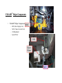
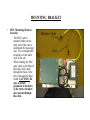
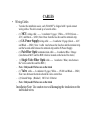
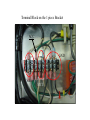
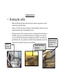
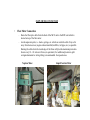
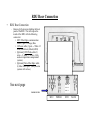
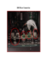
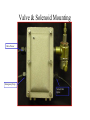
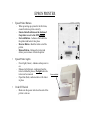
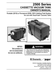
F-RAMS®
Installation Manual
Rev 2.0
Index
Major Components
Page 3
Equipment needed
Page 4
General Instruction
Page 5
Pre Installation Electrical
Page 6, 7 & 8
Mounting , Cable and Routing
Page 9 - 13,
RDU Meter Connection & Power Hook-up
Page 14 - 18
Valve Hook-up and E-stop
Page 19 -27
Handheld operation and setup
Page 28 - 29
Epson Printer operation
Page 30
F-RAMS ® Major Components
•
F-RAMS® Major Components RDU
–
–
–
–
RDU (Rear Display Unit)
MCU ( Master Control Unit)
2100 Handheld
Epson Printer
2100
Epson
Printer
MCU
Equipment Needed
•
Equipment Needed :
– 1/2” and 1 1/4” hole punch and rubber grommets.
– Power drill with bits. CAUTION! Do not use electric drill around LPG.
– Assorted bolts and nuts for mounting to truck cab floor - length determined by the thickness of
the cab floor.
– Digital Voltmeter.
– Pliers
– Screwdrivers
– Socket and Allen wrenches
– Wire cutters
– Wire strippers
– Electrical tape
– Pipe dope
– Wire ties
– Make arrangements to have the meter calibrated after installation.
General Instructions
•
General Instructions:
– Unpack - Immediately upon receipt
– Carefully unpack F-RAMS® & 2100 - Always handle with care. Do Not
Drop.
– Remove and inspect the F-RAMS® unit and all of its parts , checking that
no damage has occurred during shipping.
– Match the parts against the packing slip to ensure all parts have been
included.
Note: For installation instructions for the meter and valve, refer to the
manufacturer’s meter/valve manuals.
F-RAMS® Operating Specifications
• Pre-Installation Electrical Checklist:
– Operating Specifications:
•
•
•
•
•
Idle State (not delivering product) ……. 1 Amp
Delivery Solenoids
……. 1 Amp
Printer
……. 1 Amp
Safety Factor
……. 2 Amp
Power required with safety margin
5 Amps
(continued)
Pre-Installation Checklist
• Pre-Installation Electrical Checklist (cont.):
– For proper operation of the F-RAMS® system, the truck electrical system must meet
the following requirements.
• Battery terminals and cables must be in good condition with clean, corrosion free connections.
• Battery must be charged in accordance with manufacturer’s specifications.
• Alternator output must meet total truck demand under normal use ( i.e. lights,heater,radio,hose
reel, lifts etc.) F-RAMS® requires a minimum of 5 Amps for proper operation. Typical
alternator size should be 90 Amps. (Minimum alternator size should not be less than 70
Amps)
• If a history of truck electrical problems has been indicated, corrective action must be taken
prior to F-RAMS® installation.
• Inspect all truck electrical/electronic (radios, etc.) equipment, including ignition and accessory
lines, as well as wiring for proper installation.
• Ensure a negative ground system exists on the truck.
• Ensure that the radio antenna has been installed in accordance with the manufacturer’s
specification to prevent RF interference.
VOLTAGE CHECKS
• To check the voltage requirements:
–
–
With the truck turned off - Use a Digital voltmeter and measure across the battery to determine the
battery voltage - Minimum 12.5 VDC. (This will tell you if there is a drain on the battery). Record
Voltage: _________
With the truck operating - Use a voltmeter and measure across the battery to determine the battery
voltage - Minimum of 12.67 VDC to 13.87 VDC. (This will tell you if there is a drain on the
battery.) Record Voltage: _________
CAUTION
•
•
Always disconnect the F-RAMS® system and remove the handheld computer from its cradle
before any welding on the truck.
Always disconnect the F-RAMS® system and remove the handheld computer from its cradle
before any “Jump Starting” on the truck.
MOUNTING BRACKET
•
MCU Mounting Bracket Location
– The MCU can be
mounted either on the
back wall of the cab or
underneath the passenger
seat. The recommended
location is on the back
wall of the cab.
– When running the fiber
optic cable to the back of
the truck, drill a hole
through the back of the
cab or through the floor
board. CAUTION: Be
sure to install
grommets to the holes
so the truck vibration
does not cut through
the cable.
Battery Cable
Acc.
Mounting Bracket
CABLES
• Wiring Cables
– To make the installation easier, each F-RAMS® is shipped with 3 quick connect
wiring cables. This kit is made up of several cables.
– (1) MCU wiring cable ------ 3 conductor 18 gage ( White --- 12VDC,Green --ACC, and Black --- GND ) Note: Runs from the fuse box and the terminal strip.
– (2) I.S. Power Supply wiring cable ----- 2 conductor 18 gage (Green --- ACC
and Black --- GND ) Note: 1 cable runs between the fuse box and the terminal strip
and the Second cable between the terminal strip and the IS Power Supply.
– (1) Pair Fiber Optic communication cable ---- 2 conductor Blue / Orange
(runs between MCU and the RDU which is located on the back of the truck)
– (1) Single Valve Fiber Optic cable ----- 1 conductor / Blue ( runs between
the Valve control box and the RDU )
– Note : Only need if Valves are on the truck
– (1) Valve cable ---- 2 conductor 18 gage ( White --- 12VDC and Black --- GND )
Note: runs between the truck cab and the valve control box.
– (2) Ground Straps ( Braided ) MCU to I.S. Barrier
– Note : Only need if Valves are on the truck
Installation Note: Use caution to avoid damaging the insulation on the
individual wires.
Terminal Block on the 1 piece Bracket
ACC
GND
Valve
Power
MCU
CABLE ROUTING
• Routing the cable
–
–
–
Drill 1/2
inch hole
Make sure that the fiber optic cables that exit the cab have protection over their
connectors to keep them clean.
Punch a 1/2” hole in the cab for wiring exit. On tilt-cab trucks make sure to leave
enough slack in the cable for maintenance access.
Push the connector with its protective end (covers) through the hole and route to
the RDU, storing any excess cable inside the truck cab. Remove the protective
covers on the fiber optic cable before installing it in the RDU. At the cable exit
point from the cab, use a grommet to seal holes that were drilled in the cab. This Secure every 18 will protect the cable from wear due to cab vibration.
24 inches with
wire ties
Install grommets
in holes
FLOW METER CONNECTION
•
Flow Meter Connection
–
–
Route the fiber optic cable from the back of the MCU unit to the RDU unit which is
located on top of the flow meter.
Avoid suspension parts, i.e. shocks, springs, etc. which can crush the cable. Stay as far
away from heat sources (engine exhaust manifold, mufflers, tail pipes, etc.) as possible.
Running the cable down the inside edge of the frame will provide maximum protection.
Secure every 18 - 24 inches with ties (or equivalent). For additional protection, split
corrugated automotive wiring tubing is recommended. In exposed areas.
Neptune Meter
Liquid Controls Meter
RDU Rear Connection
•
RDU Rear Connection
–
Remove (6) Seal screws holding the back
panel of the RDU. This will expose the
inside of the RDU with the following
connectors:
• MCU Fiber Optic communication
cable (1) pair -- Orange, Blue
• I.S.Power cable (1) pair --- White 12
volts (Switch hot), Black (GND).
• [Optional] RTD Probe cable (3)
wires --2 - Reds, 1 - White (Only
used on temperature compensated
systems.)
• [Optional] Valve Fiber Optic cable
(1) Blue Fiber Optic. (Only used on
systems with valves.)
See next page
R R W
E E H
D D T
INSIDE COVER
MCU
POWER
RTD
VALVE
RDU Rear Connection
Temp Probe
O
R
A
N
G
E
O
MCU
fiber
optic
B
L
U
E
B W
L
H
K
T
Power
R R
W
E
E
H
d
d
I
T
E
Valve
Fiber
Optic
Tilt Cabs
•
Cab-over Trucks
– Be careful when locating the exit
points of the fiber optic cable from
the RDU. The entrance point must
be as close to the pivot point of the
cab as possible. A position on the
line with MCU will keep the
harness out of the way. Be sure to
allow enough slack to
accommodate pivoting of the cab.
– For convenience, a 35-foot fiber
optic cable along with optional
lengths of 25, 20, and 15-foot
cable are available.
Conventional Cab
CAB HOOK-UP
•
ACC. hook-up and 12VDC hook-up
– First locate the ACC. position on the fuse box by using a trouble light or a volt meter.
– With the truck turned OFF, connect the test light, by connecting the alligator clip to ground.
Use the other end of the test light to touch the end of the fuse.
• Note: The test light will light when you come in contact with a 12 volt source.
– After locating an ACC. line, test to ensue that it is a true ACC.
• Note: If it is a ACC. Line the test light will go On and OFF as you turn the key from
the OFF to ACC. Position, connect the Green wire from terminal strip the ACC. Fused
position to the.
– Locate Black Cable attach the White wire to the Truck Battery ( Positive ) and the Black
wire to the (Negative) or chassis ground. Keep in mind that the wire should be routed out of
the way of foot traffic and where it will not be cut. .
Note: When routing the cable to the fuse box, use care to keep it out of the way of foot traffic. A
recommended route for the cable is under the floor mat behind the driver’s seat and down
through the door channel to the fuse box. The floor mat will provide protection to the cable
and the channel will keep it safe from foot traffic.
----LPG---
Valve & Solenoid Mounting
Valve Power
Emergency Stop
Valve Fiber
Optic
Valve BOX
LPG Valve Wiring Diagram
Power Cable
Valve Fiber Optic
Cable from RDU
Solenoid Valve
Fiber Optic
Connector
Solenoid Terminal Block
Connector
S1- for single stage (LPG)
)
Fuel Oil Valve Wiring Diagram
Power Cable
Valve Fiber Optic
Cable from RDU
Solenoid Valve
Fiber Optic
Connector
Solenoid Terminal Block
Connector
2 – Stage Valve
BLK
BLK
Note: The wires can be RED or Black
S1- for first stage
S2 – for second stage
Valve Wiring for LPG
(12 volts)
GND
S2
Power Input
S1
LPG - Solenoid hookup 12VDC & S1
When the Solenoid is de-energized you will see 12 volts on both Red or Black wires.
When it is energized you will see 12 volts on the middle wire and .7 volts on the end
wire.
Note: The 2 middle screws (of the solenoid terminal) will always have 12 volts unless
there is a blown fuse or the E-Stop switched is in the off position.
Valve Wiring for Fuel Oil
12 Volt Power Input
Note: When
hooking up the
solenoid it
doesn’t matter
which wire is
attached to what
position just
make sure it
follows good
wiring practice.
Note:
S1 is setup single
stage or LPG
Fiber Optic
GND
S1 12 volts S2
S2 is setup for dual
stage solenoids or
preset and can be
adjusted in Product
set-up.
Note: Green
wires generally
GND.
When the Solenoid is de-energized you will see 12 volts on both Red or Black wires or
White and Black . When it is energized you will see 12 volts on the middle wire and .7
volts on the end wire.
Note: The 2 middle screws (of the solenoid terminal) will always have 12 volts unless
there is a blown fuse or the E-Stop switched is in the off position.
E-Stop Box
Emergency Shut-Off Switch Wiring
Diagram
Power Cable
To Valve Control Box
LC Meter
Connection
Neptune
Meter 2 inch
VEHICLE CRADLE
•
Handheld Computer Vehicle Cradle
– Bench Seat Mount
– Split Seat Mount
•
Vehicle Cradle Connection
– Connect the white wire to the 12 volts ( Hot ) and the black wire to negative or to
chassis (GND) as found in the terminal block section.
Bench Seat Mount
Split Seat Mount
EPSON PRINTER
•
Epson Printer Buttons
–
–
–
–
–
•
Epson Printer Lights
–
–
–
•
When powering up system for the first time,
ensure that device prints correctly.
Ensure that all switches on the bottom of
the printer are set to the OFF position.
Forward Button - Advances the ticket into
the printer and locks it into place.
Reverse Button - Back the ticket out of the
printer.
Release Button - Releases the ticket and
allows you to remove it from the printer.
Power light (Green) - indicates when power is
on.
Release Light (Green) - indicates when the
ticket is locked in place or No light when the
ticket can be removed.
Paper Out (Red) - indicates there is No ticket
in place.
On & Off Switch
–
Make sure the power switch on the side of the
printer is turn on.
Power switched
F-Rams®
F-Rams®
Suite 310
4749 Williams Dr.
Georgetown, TX 78628
Phone (512) 868-8101
Fax (512) 868-9115
E-Mail: [email protected]