1
P73055/F1D108-OSD/EU/man.qxd
4/21/00
2:25 PM
Page 1
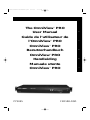
The OmniView™ PRO
User Manual
Guide de l’utilisateur de
l’OmniView™ PRO
OmniView™ PRO
Benutzerhandbuch
OmniView™ PRO
Handleiding
Fr
De
Ne
Manuale utente
OmniView™ PRO
P73055
En
F1D108-OSD
It
P73055/F1D108-OSD/EU/man.qxd
4/21/00
2:25 PM
Page 2
P73055/F1D108-OSD/EU/man.qxd
4/21/00
2:25 PM
Page 3
Table of Contents
English . . . . . . . . . . . . . . . . . . . . . . . . . . . . . . . . . . . . . . . . . . . . . . 1
En
Français (Europe) . . . . . . . . . . . . . . . . . . . . . . . . . . . . . . . . . . . . 19
Fr
Deutsch . . . . . . . . . . . . . . . . . . . . . . . . . . . . . . . . . . . . . . . . . . . . 38
De
Nederlands
Ne
. . . . . . . . . . . . . . . . . . . . . . . . . . . . . . . . . . . . . . . . . 59
Italiano . . . . . . . . . . . . . . . . . . . . . . . . . . . . . . . . . . . . . . . . . . . . . 77
It
P73055/F1D108-OSD/EU/man.qxd
4/21/00
2:25 PM
Page 4
P73055/F1D108-OSD/EU/man.qxd
4/21/00
2:25 PM
Page 1
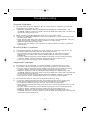
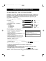
Introduction
Thank you for purchasing the Belkin Components OmniView™ PRO KVM switch. Controlling
8 PCs from one keyboard, mouse and monitor has never been easier!
The OmniView™ PRO gives you the ultimate in control. Compatible with AT and PS/2 style
computers, it is loaded with features such as On-Screen Display, Integrated Mouse
Conversion Technology and separate DB25 daisy-chain ports. It has complete keyboard and
mouse emulation for error-free boot-ups, plus Microsoft® IntelliMouse® support. The
OmniView™ PRO is also designed to handle the most demanding resolutions up to 1600 x
1200, without any noticeable degradation in image quality. Switching can be done through
the advanced On-Screen Display Menu, convenient front-panel pushbutton, or keyboard
"Hot" key commands. And if you wish to control a Macintosh® computer, simply add the
Belkin MAC Adapter™ for even more system control.
Features
• Allows a user to control eight computers from one keyboard, mouse and monitor
• On-Screen Display menu gives the user a visual interface to naming and selecting
computers
• Integrated Mouse Conversion Technology allows connection of AT-style computers that
have serial mouse ports while using a PS/2 mouse only at the console
• Keyboard and mouse emulation for error-free boot-ups
• Microsoft® IntelliMouse® support and emulation
• Up to 1600 x 1200 resolution support
• DB25 Daisy-Chain ports - allows control over as many as 128 computers through 16 banks
of OmniView™ PRO units
• Supports both AT and PS/2 style keyboards (AT requires AT-PS/2 adapter)
• Supports VGA, SVGA and Multisync monitors
• Uses inexpensive and commonly found standard cables
• On-Screen Display, pushbutton or keyboard "Hot" key command switching
• AutoScan mode for even more convenience
• Audible feedback when switching
• Recalls CAPS LOCK, NUM LOCK and SCROLL LOCK keys' status for each
computer automatically
• Front-panel status LEDs
• Works with OmniView™ PS/2 MAC Adapter™
• No software required
• One year product warranty
Package Contents
OmniView™ PRO 8-Port
12VDC, 1000mA power supply
This manual
Registration card
Two rackmount brackets
Mounting screws
F1D108-OSD
F1D108-PWR-UK
P73055
P72009
1
En
P73055/F1D108-OSD/EU/man.qxd
4/21/00
2:25 PM
Page 2
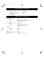
Technical Specifications
Console Connectors:
Keyboard:
Mouse:
Monitor:
6 pin MiniDIN
6 pin MiniDIN (for PS/2 mouse)
DB9 male (for spare serial mouse)
HDDB15 female
Computer Port Connectors:
Keyboard:
6 pin MiniDIN
Mouse:
6 pin MiniDIN (for PS/2 mouse)
DB9 male (for serial mouse)
Monitor:
HDDB15 male
Dimensions:
Width:
Height:
Depth:
444.5 mm
63.5 mm
165.1 mm
Weight:
Operating Temp:
Storage Temp:
Humidity:
2.7 kg
0~40 deg. C
-20 ~ 60 deg. C
0~80% RH, non-condensing
2
P73055/F1D108-OSD/EU/man.qxd
4/21/00
2:25 PM
Page 3
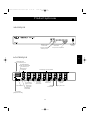
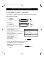
Product Detail
FRONT PANEL
En
Current Active
Bank Display
Bank Select/
Scan Button
Current Active
Port Displays
Port Select Button
REAR PANEL
SLAVE INPUT DB25 Daisy-chain port
MASTER INPUT SLAVE OUTPUT
DB25 Daisy-chain port
CONSOLE
connectors
PC PORT connectors
VGA monitor
connector
DC power
jack
DIP
switches
PS/2 mouse
connector
Optional serial
mouse connector
Serial mouse
output
Keyboard output
Keyboard
connector
3
VGA signal
output
PS/2 mouse output
Power
Switch
P73055/F1D108-OSD/EU/man.qxd
4/21/00
2:25 PM
Page 4
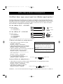
List of Parts Needed
Make sure you have the right cables!
The OmniView ™ SE requires cables to connect the eight computers you will be controlling.
Below are the Belkin part numbers and their descriptions. We recommend purchasing Cable
Kits based on the type of mouse port your computer uses. Cable kits have all the cables you
need to connect one computer to the OmniView ™ SE:
PS/2 Cable Kit - A3X982
Includes:
• 2 x F2N036-06
• 1 x F2N025-06-T
6 pin MiniDIN
HDDB15
AT Cable Kit - A3X939
5 pin DIN
Includes:
• 1 x F3A510-06
• 1 x F2N025-06-T
• 1 x F2N209-06-T
• 1 x F2N017
(see below for descriptions of each)
DB9
HDDB15
Individual Cables and Adapters:
• PS/2 cable for keyboard and mouse ports
6 pin MiniDIN male/male
Part# F2N036-XX
Daisy-Chain Cable
• DB25 Male/Male,
61cm with ferrite
Part # F1D108-CBL
• Standard VGA cable for monitor port
HDDB15 male/female with thumbscrews
Part# F2N025-XX-T
Optional 19" (48.3cm) Rackmount Kit
• Serial extension cable for serial mouse
DB9 male/female with thumbscrews
Part# F2N209-XX-T
• 48.3cm, 1.5u high
Part # F1D103
• AT keyboard cable for AT-style keyboard port
5 pin DIN male/male
Part# F3A510-XX
• AT to PS/2 keyboard adapter
5 pin DIN female/6 pin MiniDIN male
Part# F2N017
5 pin
6 pin MiniDIN Male
DIN Female
Other Cables and Adapters:
• High-resolution/high-refresh rate VGA cable for monitor port
HDDB15 male/female with thumbscrews
Part# A3H981-XX
• PS/2 to AT keyboard adapter - for use with a computer having an AT-style keyboard port
6 pin MiniDIN female/ 5 pin DIN male
6 pin MiniDIN Female
5 pin DIN Male
Part# F2N018
NOTE: The "XX" in the part number represents the length in feet.
4
P73055/F1D108-OSD/EU/man.qxd
4/21/00
2:25 PM
Page 5
Hardware Installation
Bank 0 (Master)
1
2
3
4
5
6
7
8
En
Bank 1 (slave)
9
10
11
12
13
14
15
16
17
18
19
20
21
22
23
24
125
126
127
128
CONSOLE
Keyboard,
mouse and
monitor
Bank 2 (slave)
etc...
Bank F (slave)
etc...
121
122
123
124
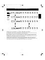
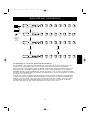
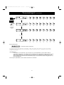
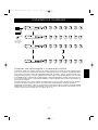
Single-unit operation or Daisy-chained operation
The OmniView™ PRO has the capability to be daisy-chained to 15 more units (for a total of
16), giving the user control over a maximum of 128 computers!
Each OmniView™ PRO unit is defined as a BANK. See diagram above for more information.
BANK numbers range from 0 to F (hexadecimal), for a total of 16 BANKs. BANK 0 is the
MASTER bank, while banks 1 through F are slave banks. The MASTER bank is the unit that
connects to the console keyboard, mouse, and monitor.
The DIP switches must be set correctly for proper identification and usage. See the next
section for the actual settings. If you are using the OmniView™ PRO in a single-unit
configuration, it must be set as the MASTER (BANK 0). If it is to be used as a slave unit,
then it must be set to any unused unique bank number from 1 through F.
5
P73055/F1D108-OSD/EU/man.qxd
4/21/00
2:25 PM
Page 6
Hardware Installation
(continued)
PLEASE FOLLOW THIS INSTALLATION PROCEDURE EXACTLY. NOT DOING SO MAY RESULT
IN KEYBOARD AND/OR MOUSE ERRORS, OR FAULTY OPERATION.
WARNING: Before attempting to connect anything to the OmniView™ PRO or
the computers, make sure everything is powered off. Plugging and unplugging
cables may cause irreversible damage to your computers and the OmniView™
PRO. Belkin Components will not be held responsible for damage caused.
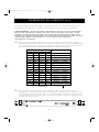
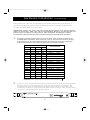
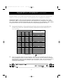
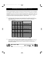
1.
Set the DIP switches. If you have only one OmniView™ PRO, use the MASTER bank setting.
If the OmniView™ PRO you are using will be daisy-chained off another unit, use a unique
slave setting. Please refer to the previous section for more information.
3
ON
DIP SWITCH #
4
5
BANK ADDRESS
6
ON
ON
OFF
ON
OFF
ON
ON
OFF
OFF
ON
ON
ON
ON
ON
ON
ON
ON
OFF
OFF
ON
ON
OFF
OFF
BANK 0
BANK 1
BANK 2
MASTER
slave
slave
BANK 3
slave
ON
BANK 4
slave
OFF
OFF
ON
ON
BANK 5
BANK 6
slave
slave
OFF
OFF
ON
BANK 7
slave
ON
ON
ON
OFF
BANK 8
slave
OFF
ON
OFF
ON
OFF
OFF
ON
ON
ON
OFF
OFF
OFF
ON
ON
OFF
OFF
BANK 9
BANK A
BANK B
BANK C
slave
slave
slave
slave
OFF
ON
ON
OFF
OFF
OFF
OFF
OFF
BANK D
slave
BANK E
slave
OFF
BANK F
slave
OFF
OFF
OFF
NOTE: "ON" is down
2. Find a convenient place to put your OmniView
PRO. Its 48.3cm form factor makes it ideal
for 48.3cm racks. When mounting to a rack, attach the included brackets to the sides of
the OmniView™ PRO. Take note of the length of your cables so that your computers,
OmniView™ PRO, keyboard, mouse, and monitor are distanced properly.
™
6
P73055/F1D108-OSD/EU/man.qxd
4/21/00
2:25 PM
Page 7
Hardware Installation
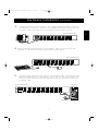
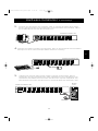
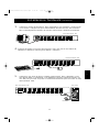
3.
(continued)
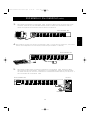
Connect the monitor to the OmniView™ PRO. Using the attached cable, or the one
included with your monitor, connect it to the HDDB15 female port on the back of the
OmniView™ PRO labeled with the monitor symbol at the CONSOLE section.
Back of OmniView™ PRO
En
4. Connect the keyboard and mouse to the OmniView
™
PRO. If you have an AT-style
keyboard, you will need an AT-PS/2 adapter (Belkin Part# F2N017).
Back of OmniView™ PRO
PS/2 Mouse
PS/2 Style Keyboard
5.
Connect the first computer's VGA cable to the OmniView™ PRO. Using the VGA cable
(Belkin Part# F2N025-XX-T or A3H981-XX), connect the male end of the cable to the
VGA port on the computer, and the female end on the PC1 VGA port at the back of
OmniView™ PRO.
Back of OmniView™ PRO
Back of PC
F2N025-XX-T
7
P73055/F1D108-OSD/EU/man.qxd
4/21/00
2:25 PM
Page 8
Hardware Installation
6.
(continued)
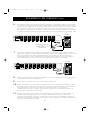
Connect the first computer's mouse cable to the OmniView™ PRO. If using a PS/2 cable
(Belkin Part# F2N036-XX), connect one end to the PS/2 mouse port on the computer, and
the other end to the PC1 PS/2 mouse port on the back of the OmniView™. If using a serial
mouse cable (Belkin Part# F2N209-XX-T), connect one end to a DB9 serial port on the
computer, and the other end to the PC1 DB9 serial mouse port on the back of the
OmniView™ PRO.
Back of PC
Back of OmniView™ PRO
F2N036-XX for PS/2 mouse
OR
F2N209-XX-T for serial mouse
7.
Connect the first computer's keyboard cable to the OmniCube™. Using another PS/2
cable (Belkin Part# F2N036-XX), connect one end to the PS/2 keyboard port on the
computer, and the other end to the PC1 keyboard port on the back of the OmniCube™. If
your computer has an AT-style keyboard port, you will need a PS/2-AT keyboard adapter
(Belkin Part# F2N018).
Back of PC
Back of OmniCube™
F2N036-XX
8.
Double check all of the connections. Make sure the keyboard and mouse cables go to the
correct ports.
9.
Repeat steps 5-7 for the remainder of the computers.
10. Attach the power supply to the power supply connector at the back of the OmniView
™
PRO. Plug this into any available AC outlet. Flip the power switch on the front of the
OmniView™ PRO. You should see the LED for Port 1 on the front panel blink, and hear a
beep. Power up your monitor.
11. You can now power up all your computers simultaneously. The first computer will show up
on the monitor. Check to see if the keyboard, mouse and monitor work.If this is okay, press
the “SELECT” button and check the functionality of the other computers. If you find any
errors, double-check all of the cable connections.
8
P73055/F1D108-OSD/EU/man.qxd
4/21/00
2:25 PM
Page 9
Hardware Installation
(continued)
NOTE: Avoid pressing any keys on the keyboard or moving the mouse if the currently
selected port has a computer that is in the process of booting up. This may cause
the computer to not detect, or initialize the keyboard or mouse drivers properly.
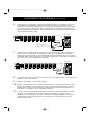
Daisy-Chaining the OmniView™ PRO:
The OmniView™ PRO can be daisy-chained with additional OmniView™ PRO units through
the DB25 daisy-chain ports. The F1D108-CBL daisy-chain cable is required (not included) for
proper operation. Please refer to the example below. Here, four OmniView™ PRO units are
cascaded together for control over 32 computers. Recall that a maximum of 16 OmniView™
PRO units can be cascaded together for control over 128 computers. Recall that the DIP
switches on the MASTER unit must be set to BANK 0, and the slave units set to a unique
BANK (any from 1 through F). See the beginning of this section for more information on the
DIP switch settings.
MASTER
(Bank 0)
Cable 1
slave
(Bank 1)
Cable 2
slave
(Bank 2)
Cable 3
slave
(Bank 3)
• After setting the DIP switches on the slave unit, connect the computers using the same
procedure outlined in steps 5 to 9 in the previous section. DO NOT POWER UP THE
COMPUTERS YET.
• Using the F1D108-CBL daisy-chain cable, connect one end to the "Master Input/ Slave
Output" of the unit. Refer to the diagram above.
• If the previous unit is the MASTER, then the other end of the cable connects to
the "Master Input/Slave Output" port of the MASTER (such as cable 1 in the
diagram above).
• If the previous unit is a slave, then the other end goes to the "Slave Input" port of
the previous slave unit (such as cables 2 and 3 in the diagram above).
9
En
P73055/F1D108-OSD/EU/man.qxd
4/21/00
2:25 PM
Page 10
Hardware Installation
(continued)
• Upon connecting the daisy-chain cable to the previous unit, it should automatically
power up if the previous unit is powered up. However, it is still recommended that the
power supply be used with the slave unit. You will see the LED display on the front
panel show the units bank address setting.
• RESET the MASTER unit by pressing the BANK/SCAN and CHANNEL buttons
simultaneously. This is necessary for the MASTER unit to detect the newly added slave unit.
• Verify that the MASTER unit has detected the new slave by pressing the BANK/SCAN
button. If it detected the new slave properly, the LED display on the MASTER will
register the slave units bank address. If you have many slave units, you may have to
press the BANK/SCAN button many times to cycle through all of the preexisting slave
units before reaching the newly added unit.
• Now you can power up the computers connected to the newly added slave unit. After
all the computers have booted up, you may need to RESET the MASTER unit again to
detect the presence of powered computers on the new slave unit.
NOTE: The OmniView™ PRO can also be daisy-chained to OmniView™ SE units (F1D102 and
F1D104 only). This gives the user more selection and flexibility. When doing this, it is
desirable to have the OmniView™ PRO as the MASTER unit because of the On-Screen
Display (OSD) menu feature. Thus, all the units will benefit from the OSD control, even
if the OmniView™ SE does not have the OSD feature.
10
P73055/F1D108-OSD/EU/man.qxd
4/21/00
2:25 PM
Page 11
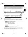
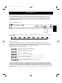
Usage
Selecting which computer to operate can be done either by On-Screen Display, the
CHANNEL button, or through keyboard hot-key commands. You will notice that after the
OmniView™ PRO switches to another computer, the mouse will be inoperative for about
1-2 seconds. This is normal operation and ensures that proper mouse synchronization
is established.
En
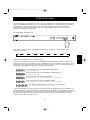
The CHANNEL Button:
Pressing the CHANNEL button cycles you through all the ports, including inactive ports.
1
2
3
4
5
6
7
8
Keyboard Hot-Key commands:
You can also conveniently command the OmniView™ PRO to switch ports through simple
keyboard key sequences. To send commands to the OmniView™ PRO, the SCROLL LOCK
key must be pressed twice within 2 seconds. You will hear a beep for confirmation. Below
are the different commands:
Switch to PREVIOUS ACTIVE port
(on the same BANK)
Switch to NEXT ACTIVE port
(on the same BANK)
Switch to the PREVIOUS BANK
(by default, selects first active port on that BANK)
Switch to the NEXT BANK
(by default, selects first active port on that BANK)
Directly switches to port Y on BANK X
X = {0 to F} hexadecimal, Y = {1 to 8}
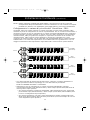
You can switch directly to any port by giving the OmniView™ PRO the BANK and PORT
numbers. For instance, if you press SCROLL LOCK SCROLL LOCK [2] [5], the computer on
PORT 5 of the OmniView™ PRO set to BANK 2 will be selected. In the following diagram,
that is PC # 21. Hence, if you only have one OmniView™ PRO, the first key (X) must be "0".
11
P73055/F1D108-OSD/EU/man.qxd
4/21/00
2:25 PM
Page 12
Usage
Bank 0 (Master)
Bank 1 (slave)
CONSOLE
(continued)
1
2
3
4
5
6
7
8
9
10
11
12
13
14
15
16
17
18
19
20
21
22
23
24
121
122
123
124
125
126
127
128
Keyboard,
mouse and
monitor
Bank 2 (slave)
etc...
Bank F (slave)
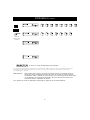
AutoScan Mode:
Enable AutoScan mode
In AutoScan mode, the OmniView™ PRO remains on one port for a number of seconds, before
switching to the next. This time interval is set in the On-Screen Display menu.
NOTE: There is no mouse or keyboard control in this mode. This is necessary to prevent errors.
Otherwise, if the user is moving the mouse or using the keyboard when the OmniView™
PRO switches to the next port, data flow is interrupted and will cause erratic mouse
movement and/or the wrong characters to show up when using the keyboard.
To get out of AutoScan mode, press the SPACEBAR.
12
P73055/F1D108-OSD/EU/man.qxd
4/21/00
2:25 PM
Page 13
Usage
(continued)
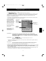
On-Screen Display Menu Control:
Enable the On-Screen Display Menu
To get into the On-Screen Display (OSD) menu, press SCROLL LOCK, SCROLL LOCK,
SPACEBAR. Immediately, the OSD overlay screen appears. This screen is generated by the
OmniView™ PRO, and does not affect your computers or running software in any way.
The main OSD screen
menu is shown on the
right. It shows the
currently selected
BANK. If you have only
one OmniView™ PRO,
it will say "BANK 0".
The current selected
port is shown in RED.
A "✹" indicates that
the computer
connected to that port
is powered up.
Currently
selected
Port is
in RED
Currently
selected
Bank
Address
Belkin: F1D108-OSD
1. WIN98
✹
2. NT SERVER
✹
3. MAC OS8
✹
4. NET SRVR
✹
5. UNIX SRVR
✹
6. CHANNEL 6
7. CHANNEL 7
8. CHANNEL 8
BANK 0
“✹” indicates
PC is powered
(TAB): FUNCTION / HELP
:PgUp
:PgDn
• You can navigate through the active ports by using the arrow keys. The OSD menu will
only allow you to move to active ports.
NOTE: If a computer is connected and is powered up, but the OSD menu does not display
a "✹", you will have to RESET the OmniView™ PRO to re-detect the powered
computers. This is done by simultaneously pressing the BANK/SCAN and CHANNEL
buttons on the front panel.
NOTE: Pressing
will reset the keyboard ports of the OmniView™ Pro.
• Pressing the INSERT key allows you to rename the port. Press ENTER to complete.
NOTE: Inadvertently pressing the SCROLL LOCK, SCROLL LOCK, DELETE keys will erase
any given names on the OSD menu.
• Pressing the ESC key exits the current screen.
• To view a different BANK, pressing the PAGE UP key goes to a previous BANK, while the
PAGE DOWN key brings you to the next BANK.
• Once you have selected a computer on the menu, press ENTER to switch to that port.
• Pressing the TAB key opens up the Function menu. In this menu, you can select the
SCAN TIME and the DISPLAY TIME.
13
En
P73055/F1D108-OSD/EU/man.qxd
4/21/00
2:25 PM
Page 14
Usage
SCAN TIME:
Amount of time the OmniView™ PRO stays
on one port before switching to the next
port when in Scan Mode.
DISPLAY TIME:
Amount of time the OSD Menu or Port
Name remains displayed on-screen after
making a port selection.
(continued)
SCAN TIME:
■ 7sec ■ 15sec
DISPLAY TIME:
■ 7sec ■ 15sec
■ 30sec
■ 60sec
■ 30sec
■ 60sec
[↕]: SELECT
(INS): RENAME
(Enter): COMPLETE
(Esc): Exit
NOTE: If there are slave units present, the SCAN TIME and DISPLAY TIME settings are set on
the MASTER unit only, and need not be set on the slave units.
The BANK/SCAN Button:
Pressing the BANK/SCAN button cycles you through all the active BANKS (if there are slave
units present) and then puts the unit in AutoScan mode. If the unit is a single MASTER unit,
pressing the button immediately invokes AutoScan mode. This is evident by a long BEEP,
followed by two short beeps.
14
P73055/F1D108-OSD/EU/man.qxd
4/21/00
2:25 PM
Page 15
Troubleshooting
General Problems:
Q: The OSD menu does not display a "✹" on a port where a computer is connected
and powered up. What do I do?
A: • RESET the OmniView™ PRO by simultaneously pressing the “BANK/SCAN” and
CHANNEL buttons on the front panel. Access the OSD menu again and it should have
re-detected all the active ports.
Q: When cascading, the MASTER unit does not see the slave unit(s).
A: • Refer to the Hardware Installation section for information on how to properly connect
the daisy-chain cable.
• Make sure that the daisy-chain cable that you are using is the F1D108-CBL. Using any
other cable will not guarantee proper operation or video quality.
• RESET the MASTER OmniView™ PRO.
• Although a power supply is not necessary to make the slave unit work, try adding a
power supply.
Monitor/Video Problems:
Q: I am getting ghosting, shadowing or fuzzy images on my monitor. What do I do?
A: • Check the cables and make sure they are inserted properly.
• Your resolution and/or refresh rate is extremely high, or your cable is too long.
Replace your VGA cables with coaxial, double-shielded cables such as Belkin
A3H981-XX.
• Check to make sure that the power adapter is plugged in and is working properly.
It must be 12VDC, 1000mA minimum. Make sure the power switch is on.
• Lower you refresh rate and/or screen resolution settings.
Keyboard Problems:
Q: The keyboard is not detected, or a keyboard error is reported during boot-up.
A: • Check the cables and make sure they are inserted properly in the correct ports.
• Check to make sure that the power adapter is plugged in and is working properly.
It must be 12VDC, 1000mA minimum. Make sure the power switch is on.
• RESET the OmniView™ PRO by simultaneously pressing the “BANK/SCAN” and
CHANNEL buttons on the front panel. Access the OSD menu again and it should have
re-detected all the active ports.
• Do not press any keys on the keyboard while the selected computer is booting up.
This is true for any PC, whether stand-alone or connected to a KVM switch.
Q: The computers boot up fine, but the keyboard does not work.
A: • Check the cables and make sure they are inserted properly in the correct ports.
• Make sure the keyboard works when directly plugged into the computers.
• Try a different keyboard, but use only 101, 102 or 104-key keyboards.
• Make sure that the keyboard driver is for 101, 102 or 104-key keyboards, and not old
XT keyboards.
• Check to make sure that the power adapter is plugged in and is working properly.
It must be 12VDC, 1000mA minimum. Make sure the power switch is on.
• RESET the OmniView™ PRO by simultaneously pressing the BANK/SCAN and
CHANNEL buttons on the front panel. Access the OSD menu again and it should have
re-detected all the active ports.
15
En
P73055/F1D108-OSD/EU/man.qxd
4/21/00
2:25 PM
Page 16
Troubleshooting
(continued)
PS/2 Mouse Problems at the console or computers:
Q: The mouse is not detected during boot-up.
A: • Check the cables and make sure they are inserted properly in the correct ports.
• Check your computer/motherboard documentation making sure that the PS/2 mouse
port (or IRQ) is enabled.
• Make sure the mouse is directly plugged into the computer. Rebooting is necessary
when trying this. If the computer still does not detect the mouse, then your computer’s
PS/2 mouse port has a problem.
• RESET the OmniView™ PRO by simultaneously pressing the BANK/SCAN and CHANNEL
buttons on the front panel. Access the OSD menu again and it should have re-detected
all the active ports.
Q: The computers boot up fine, but the mouse does not work.
A: • Check the cables and make sure they are inserted properly in the correct ports.
• Make sure the mouse works when directly plugged into the computer. Rebooting is
necessary when trying this. If the mouse pointer still does not move, then either your
PS/2 mouse port or the mouse itself has a problem.
• Try a different mouse.
• Make sure the mouse is a true PS/2 mouse. A combo mouse will work just as long as it is
set for PS/2 mode with the correct adapter. A serial-only mouse with a combo mouse
adapter WILL NOT work.
• Check to make sure that the power adapter is plugged in and is working properly.
It must be 12VDC, 1000mA minimum. Make sure the power switch is on.
• RESET the OmniView™ PRO by simultaneously pressing the BANK/SCAN and CHANNEL
buttons on the front panel. Access the OSD menu again and it should have re-detected
all the active ports.
Q: When I switch from one port to another, mouse movement is completely erratic.
What do I do?
A: • RESET the OmniView™ PRO by simultaneously pressing the BANK/SCAN and CHANNEL
buttons on the front panel. Access the OSD menu again and it should have re-detected
all the active ports.
• Make sure you do not have more than one mouse driver. Make sure that the driver is
either for a Standard PS/2 or Microsoft®-compatible PS/2 mouse. Try to obtain the latest
version from your hardware manufacturer.
• If you are using a specialized mouse such as a cordless mouse, scrolling mouse or mice
with more than 2 operational buttons, use generic PS/2 mouse drivers. Non-standard
mice often use non-PS/2 proprietary mouse protocol.
• Make sure you do not have any mouse drivers loaded in your config.sys or
autoexec.bat files.
• Avoid moving the mouse or pressing the mouse buttons when switching ports.
• Reset the mouse to resume proper mouse movement simply by unplugging the mouse
from the front of the OmniView™ PRO for about 2-3 seconds, and plugging it in again.
Problems with computers using the serial mouse output:
Note: The OmniView™ PRO has Integrated Mouse Conversion Technology. This technology
converts the PS/2 mouse signals at the console to serial mouse signals. Windows® 9x
Control Panel System applet may not display that it has detected a mouse, but the
Modem applet will show a serial mouse at a certain serial port.
Q: The computers boot up fine, but the mouse does not work.
A: • Check the cables and make sure they are inserted properly in the correct ports.
• Check the cable and make sure that it is a straight-through DB9 male/female
cable such as Belkin P/N F2N209-XX-T (XX is the length in feet).
16
P73055/F1D108-OSD/EU/man.qxd
4/21/00
2:25 PM
Page 17
Troubleshooting
(continued)
• Check your computer/motherboard documentation making sure that the serial ports
are enabled, and that there are no IRQ or base address conflicts with other serial ports
or modems.
• Plug in a serial mouse directly to your computer, and reboot. If the mouse pointer still
does not move, then there may be no serial mouse drivers installed, or the serial port
on your computer may have other conflicts or problems.
• Try a different PS/2 mouse at the console.
• Make sure the mouse (at the console) is a true PS/2 mouse. A combo mouse will work
just as long as it is set for PS/2 mode with the correct adapter. A serial-only mouse
with a combo mouse adapter WILL NOT work.
• Check to make sure that the power adapter is plugged in and is working properly.
It must be 12VDC, 1000mA minimum. Make sure the power switch is on.
• RESET the OmniView™ PRO by simultaneously pressing the BANK/SCAN and
CHANNEL buttons on the front panel. Access the OSD menu again and it should have
re-detected all the active ports.
Q: When I switch from one port to another, mouse movement is completely erratic.
What do I do?
A: • RESET the OmniView™ PRO by simultaneously pressing the BANK/SCAN and
CHANNEL buttons on the front panel. Access the OSD menu again and it should have
re-detected all the active ports.
• Make sure you do not have more than one serial mouse driver loaded. Make sure that
the driver is either for a Standard Serial or Microsoft®-compatible serial mouse.
• Avoid using a specialized mouse at the console such as a cordless mouse, scrolling
mouse or mice with more than 2 operational buttons. Non-standard mice often use
non-PS/2 proprietary mouse protocol.
• Make sure you do not have any other mouse drivers loaded in your config.sys or
autoexec.bat files.
• Avoid moving the mouse or pressing the mouse buttons when switching ports.
• Reset the mouse to resume proper mouse movement simply by unplugging the mouse
from the OmniView™ PRO for about 2-3 seconds, and plugging it in again.
Q: The wheel on the IntelliMouse® does not work on my computer. Why?
A: • The Integrated Mouse Conversion Technology converts only the standard PS/2 signals
which are the buttons and the x and y coordinate movement, but not the wheel
movement or wheel button. This is because the wheel and wheel button data use
non-PS/2 protocol.
Notea bout the Optional Serial Mouse port at the console: If you have tried all possible
troubleshooting methods, you can plug in a serial mouse (as a second mouse) at the
optional serial mouse input port. See the Product Detail Section for the diagram. This mouse
will be directly connected to the serial mouse ports on the OmniView™ PRO. Note that the
serial mouse signals will not be converted to PS/2 mouse signals, so if you have other PCs
using PS/2 mouse ports, you must keep the PS/2 mouse at the console. This serial mouse is
a second mouse, and is active only when on a computer that uses the serial mouse output.
17
En
P73055/F1D108-OSD/EU/man.qxd
4/21/00
2:25 PM
Page 18
Information
FCC Statement
DECLARATION OF CONFORMITY WITH FCC RULES FOR ELECTROMAGNETIC COMPATIBILITY
We, Belkin Components, of 501 West Walnut Street, Compton CA 90220, declare under our sole
responsibility that the product:
F1D108-OSD
to which this declaration relates:
Complies with Part 15 of the FCC Rules. Operation is subject to the following two conditions: (1) this device may
not cause harmful interference, and (2) this device must accept any interference received, including interference
that may cause undesired operation.
CE Declaration of Conformity
We, Belkin Components, declare under our sole responsibility that the F1D108-OSD, to which this declaration relates,
is in conformity with Generic Emissions Standard EN50081-1 and with Generic Immunity Standard EN50082-1 1992.
Belkin Components One Year Product Warranty
Belkin Components warrants this product against defects in materials and workmanship for one year. If a defect is
discovered, Belkin will, at its option, repair or replace the product at no charge provided it is returned during the
warranty period, with transportation charges prepaid, to the authorized Belkin dealer from whom you purchased the
product. Proof of purchase may be required.
This warranty does not apply if the product has been damaged by accident, abuse, misuse, or misapplication; if the
product has been modified without the written permission of Belkin; or if any Belkin serial number has been removed
or defaced.
THE WARRANTY AND REMEDIES SET FORTH ABOVE ARE EXCLUSIVE IN LIEU OF ALL OTHERS, WHETHER
ORAL OR WRITTEN, EXPRESSED OR IMPLIED. BELKIN SPECIFICALLY DISCLAIMS ANY AND ALL IMPLIED
WARRANTIES, INCLUDING, WITHOUT LIMITATION, WARRANTIES OF MERCHANTABILITY AND FITNESS FOR A
PARTICULAR PURPOSE.
No Belkin dealer, agent, or employee is authorized to make any modification, extension, or addition to this warranty.
BELKIN IS NOT RESPONSIBLE FOR SPECIAL, INCIDENTAL, OR CONSEQUENTIAL DAMAGES RESULTING FROM
ANY BREACH OF WARRANTY, OR UNDER ANY OTHER LEGAL THEORY, INCLUDING BUT NOT LIMITED TO LOST
PROFITS, DOWNTIME, GOODWILL, DAMAGE TO OR REPROGRAMMING, OR REPRODUCING ANY PROGRAM OR
DATA STORED IN OR USED WITH BELKIN PRODUCTS.
Some states do not allow the exclusion or limitation of incidental or consequential damages or exclusions of implied
warranties, so the above limitations of exclusions may not apply to you. This warranty gives you specific legal rights,
and you may also have other rights that vary from state to state.
belkin.com
Belkin Components
Belkin Components, Ltd.
Belkin Components B.V.
501 West Walnut Street
Compton • CA • 90220 • USA
Tel: 310.898.1100
Fax: 310.898.1111
Unit 13 • Gatelodge Close • Round Spinney
Northampton • Northants • NN3 8RX • UK
Tel: +44 (0) 1604678300
Fax: +44 (0) 1604678330
Diamantlaan 8 • 2132 WV
Hoofddorp • The Netherlands
Tel: +31 (0) 235698765
Fax: +31 (0) 235612694
© 2000 Belkin Components. All rights reserved. All trade names are registered trademarks of the respective manufacturers listed.
P73055/F1D108-OSD/f/man.qxd
4/21/00
2:31 PM
Page 19
Introduction
Nous vous remercions d’avoir choisi le commutateur OmniView™ PRO KVM de Belkin
Components. Il n’a jamais été aussi facile de commander huit PC à partir d´un seul clavier,
d´une seule souris et d´un seul moniteur !
L’OmniView™ PRO constitue le fin du fin en matière de commande de PC. Compatible avec
les ordinateurs AT et PS/2, il possède de nombreuses caractéristiques telles que le
paramétrage à l’écran OSD (On-Screen Display), la technologie de conversion de souris
intégrée et des ports DB25 de mise en cascade séparés. Il est doté d´une émulation souris
et clavier complète pour des démarrages sans erreur et il supporte la souris Microsoft®
IntelliMouse®. L´OmniView™ PRO est également conçu pour gérer les résolutions les plus
exigeantes allant jusqu’à 1600 x 1200, et ce sans dégradation visible de la qualité de
l´image. La commutation peut s´effectuer grâce au menu évolué de paramétrage à l’écran,
au bouton poussoir situé à l’avant de l´appareil, ou encore grâce aux raccourcis clavier. En
outre, si vous souhaitez commander un ordinateur Macintosh®, il vous suffit d´ajouter
l´adaptateur MAC Adapter™ de Belkin pour maîtriser encore mieux le système.
Caractéristiques
• Permet à un utilisateur de commander huit ordinateurs à partir d´un seul clavier, d´une
seule souris et d´un seul moniteur
• Le menu de paramétrage à l’écran (OSD) donne à l’utilisateur une interface visuelle pour
nommer et sélectionner les ordinateurs
• La technologie de conversion de souris intégrée permet de raccorder des ordinateurs AT
dotés de ports souris à connexion série en n’utilisant une souris PS/2 qu’au niveau de la console
• Emulation souris et clavier pour des démarrages sans erreur
• Support de la souris Microsoft® IntelliMouse® et émulation
• Supporte des résolutions allant jusqu´à 1600 x 1200
• Ports DB25 de mise en cascade. Ils permettent de commander jusqu’à 128 ordinateurs par
le biais de 16 bancs d’OmniView™ PRO
• Supporte tant les claviers AT que les claviers PS/2 (AT nécessite un adaptateur AT-PS/2)
• Supporte les moniteurs VGA, SVGA et Multisync
• Utilise des câbles standard bon marché et faciles à trouver
• Commutation par paramétrage à l’écran, bouton poussoir ou raccourci clavier
• Mode de balayage automatique garantissant une commodité accrue
• Signal sonore indiquant la commutation
• Rappelle automatiquement, pour chaque ordinateur, le statut des touches CAPS LOCK
(Verrouillage des majuscules), NUM LOCK (Verr Num) et SCROLL LOCK (Arrêt défil)
• Voyants DEL d’état (à l’avant de l’appareil)
• Fonctionne avec l’adaptateur MAC Adapter™ pour OmniView™ PS/2
• Aucun logiciel n’est requis
• Garantie produit un an
19
Fr
P73055/F1D108-OSD/f/man.qxd
4/21/00
2:31 PM
Page 20
Contenu de l’emballage :
OmniView™ PRO 8 ports
Alimentation 12VDC, 1000mA
Ce manuel
Carte d’enregistrement
Deux supports de montage en rack
Vis de montage
F1D108fOSD
F1D108-PWR-EUR
P73055
P53324
Spécifications techniques
Connecteurs de console :
Clavier :
Souris :
Moniteur :
MiniDIN 6
MiniDIN 6 (pour souris PS/2)
DB9 mâle (pour souris à connexion série de rechange)
HDDB15 femelle
Connecteurs de ports d’ordinateur :
Clavier :
MiniDIN 6
Souris :
6 MiniDIN 6 (pour souris PS/2)
DB9 mâle (pour souris à connexion série)
Moniteur :
HDDB15 mâle
Dimensions :
Largeur :
Hauteur :
Profondeur :
Poids :
Température de travail :
Température de stockage :
Humidité :
44,45 cm
6,35 cm
16,51 cm
2,7 kg
0~40 degrés Celsius
-20~60 degrés Celsius
0-80 % RH, pas de condensation
20
P73055/F1D108-OSD/f/man.qxd
4/21/00
2:31 PM
Page 21
Détails relatifs au produit
FACE AVANT
Fr
Affichage du
banc actif
Affichage du
port actif
Bouton Bank
Select/Scan (Sélection
du banc/Balayage)
Bouton de
sélection du port
FACE ARRIERE
ENTREE ESCLAVE Port DB25 de mise en cascade
ENTREE MAITRE SORTIE ESCLAVE
Port DB25 de mise en cascade
Connecteurs pour la
CONSOLE
Prise de
courant
continu
Interrupteurs
DIP
Connecteurs pour les PORTS PC
Connecteur pour Connecteur pour la
le moniteur VGA souris à connexion
série optionnelle
Sortie souris à
connexion série
Sortie clavier
Connecteur pour
la souris PS/2
Connecteur pour
le clavier
21
Sortie signaux
VGA
Sortie souris PS/2
Interrupte
ur de
courant
P73055/F1D108-OSD/f/man.qxd
4/21/00
2:31 PM
Page 22
Liste des pièces nécessaires
Vérifiez bien que vous avez les câbles appropriés !
Plusieurs câbles sont nécessaires pour raccorder à l´OmniView™ PRO les huit ordinateurs que
vous allez commander. Vous trouverez ci-dessous les numéros de pièces Belkin ainsi que leur
description. Nous vous conseillons d´acheter les kits de câbles correspondant au type de port
souris utilisé par votre ordinateur. Les kits de câbles contiennent tous les câbles nécessaires
pour raccorder un ordinateur à l´OmniView™ PRO :
Kit de câbles PS/2 – A3X982f
Contenu du kit :
• 2 x F2N036f06
• 1 x F2N025f06-T
MiniDIN 6
HDDB15
Kit de câbles AT - A3X939f
5 DIN
Contenu du kit :
• 1 x F3A510f06
• 1 x F2N025f06-T
• 1 x F2N209f06-T
• 1 x F2N017f
(Voir ci-dessous la description de chacun de ces câbles)
DB9
HDDB15
Câbles individuels et adaptateurs :
Câble de mise en cascade
• Câble PS/2 pour ports clavier et souris
MiniDIN 6 mâle/mâle
Numéro de pièce : F2N036fXX
• DB25 mâle/mâle,
0,61 mètre, avec de la ferrite
Numéro de pièce : F1D108-CBL
• Câble VGA standard pour port moniteur
HDDB15 mâle/femelle avec vis à oreilles
Numéro de pièce : F2N025fXX-T
Kit de montage en rack en option,
48,3 cm
• Câble de rallonge série pour souris à connexion série
• 48,3 cm. Hauteur : 1,5 u
DB9 mâle/femelle avec vis à oreilles
Numéro de pièce : F1D103f
Numéro de pièce : F2N209fXX-T
• Câble de clavier AT pour port clavier AT
DIN 5 mâle/mâle
Numéro de pièce : F3A510fXX
• AT to PS/2 keyboard adapter
5 pin DIN female/6 pin MiniDIN male
Numéro de pièce : F2N017f
Din 5 femelle
MiniDin 6 mâle
Autres câbles et adaptateurs :
• Câble VGA pour port de moniteur, haute résolution/taux de rafraîchissement élevé
HDDB15 mâle/femelle avec vis à oreilles
Numéro de pièce : A3H981fXX
• Adaptateur de clavier AT vers PS/2
DIN 5 femelle/ MiniDin 6 mâle
Numéro de pièce : F2N018f
MiniDin 6 femelle
DIN 5 mâle
HINWEIS: „-XX" bei den Artikelnummern steht für die Kabellänge in Fuß (1 Fuß = 0,3048 m).
22
P73055/F1D108-OSD/f/man.qxd
4/21/00
2:31 PM
Page 23
Installation du matériel
Banc 0 (Maître)
Banc 1 (esclave)
1
2
3
4
5
6
7
8
9
10
11
12
13
14
15
16
CONSOLE
Clavier, souris
et moniteur
Fr
Banc 2 (esclave)
17
18
19
20
etc.
Banc F (esclave)
21
22
23
24
125
126
127
128
etc.
121
122
123
124
Configuration en unité simple ou en cascade
L’OmniView™ PRO peut être mis en cascade avec 15 autres unités (dans une configuration
regroupant donc 16 unités au total), ce qui permet à l’utilisateur de commander jusqu’à
128 ordinateurs !
Chaque OmniView™ PRO est appelé BANC (Bank). Pour de plus amples informations,
référez-vous au schéma ci-dessus. Les numéros de BANCS sont compris entre 0 et F
(hexadécimal), avec un total de 16 BANCS. Le BANC 0 est le banc MAÎTRE (Master), tandis
que les bancs 1 à F sont les bancs esclaves. Le banc MAÎTRE est l’unité assurant le
raccordement au moniteur, à la souris et au clavier de la console.
Les interrupteurs DIP doivent être dûment positionnés afin de garantir une bonne
identification et un bon fonctionnement du système. Les différents paramètres sont
expliqués dans la section suivante. Si vous utilisez l’OmniView™ PRO dans une
configuration simple, l’OmniView sera le MAÎTRE (BANC 0). Si vous l’utilisez en tant
qu’unité esclave, il doit correspondre à n’importe quel numéro de banc unique non
utilisé de 1 à F.
23
P73055/F1D108-OSD/f/man.qxd
4/21/00
2:31 PM
Page 24
Installation du matériel
(suite)
VEUILLEZ SUIVRE SCRUPULEUSEMENT CES INSTRUCTIONS. TOUT MANQUEMENT PEUT
ENTRAÎNER DES ERREURS CLAVIER ET / OU SOURIS OU UN DYSFONCTIONNEMENT.
AVERTISSEMENT : Avant de tenter de brancher quoi que ce soit à l´OmniView™
PRO ou aux ordinateurs, vérifiez que rien n’est sous tension. En effet, si vous
branchez ou débranchez des câbles alors que des appareils sont encore sous
tension, vous pouvez endommager vos ordinateurs et l´OmniView™ PRO de façon
irrémédiable. Belkin Components ne sera pas tenu responsable des
dommages occasionnés.
1.
Positionnez les interrupteurs DIP. Si vous n´avez qu´un seul OmniView™ PRO, utilisez le
positionnement du banc MAÎTRE. Si l’OmniView™ PRO que vous utilisez est destiné à être
mis en cascade avec une autre unité, utilisez une configuration esclave unique. Pour de
plus amples informations, veuillez vous référer à la section précédente.
INTERRUPTEUR DIP n°
6
4
5
3
ON
ADRESSE DU BANC
ON
ON
OFF
ON
OFF
ON
ON
OFF
OFF
ON
ON
ON
ON
ON
ON
ON
ON
OFF
OFF
ON
ON
OFF
OFF
BANK 0
BANK 1
BANK 2
MAÎTRE
esclave
esclave
BANK 3
esclave
ON
BANK 4
esclave
OFF
OFF
ON
ON
BANK 5
BANK 6
esclave
esclave
OFF
OFF
ON
BANK 7
esclave
ON
ON
ON
OFF
BANK 8
esclave
OFF
ON
OFF
ON
OFF
OFF
ON
ON
ON
OFF
OFF
OFF
ON
ON
OFF
OFF
BANK 9
BANK A
BANK B
BANK C
esclave
esclave
esclave
esclave
OFF
ON
ON
OFF
OFF
OFF
OFF
OFF
BANK D
esclave
BANK E
esclave
OFF
BANK F
slave
OFF
OFF
OFF
REMARQUE : ON : vers le bas
2. Trouvez l’endroit idéal pour poser votre OmniView
PRO. De par sa forme et ses
dimensions, il convient parfaitement aux racks 48,3 cm. Lorsque vous le monter en rack,
fixez les supports fournis sur les côtés de l’OmniView™ PRO. Notez bien la longueur de
vos câbles afin que l’OmniView™ PRO, le clavier, la souris et le moniteur soient à la bonne
distance les uns des autres.
™
24
P73055/F1D108-OSD/f/man.qxd
4/21/00
2:31 PM
Page 25
Installation du matériel
3.
(suite)
Raccordez le moniteur à l’OmniView™ PRO. Grâce au câble inclus ou fourni avec votre
moniteur, reliez-le au port HDDB15 femelle situé à l’arrière de l´OmniView™ PRO et
assorti du symbole du moniteur dans la section CONSOLE.
Dos de l´OmniView™ PRO
Fr
4. Raccordez le clavier et la souris à l´OmniView
™
PRO. Si vous avez un clavier AT, vous aurez
besoin d´un adaptateur AT vers PS/2 (numéro de pièce Belkin : F2N017f).
Dos de l´OmniView™ PRO
Souris PS/2
Clavier PS/2
5.
Raccordez le câble VGA du premier ordinateur à l´OmniView™ PRO. Prenez le câble
VGA (numéro de pièce Belkin : F2N025fXX-T ou A3H981fXX), insérez l’extrémité mâle
du câble dans le port VGA de l’ordinateur et l’extrémité femelle dans le port VGA PC 1
situé à l’arrière de l´OmniView™ PRO.
Dos de l´OmniView™ PRO
Dos du PC
F2N025fXX-T
25
P73055/F1D108-OSD/f/man.qxd
4/21/00
2:31 PM
Page 26
Installation du matériel
6.
(suite)
Raccordez le câble de la souris du premier ordinateur à l´OmniView™ PRO. Si vous utilisez
un câble PS/2 (numéro de pièce Belkin : F2N036fXX), insérez une extrémité dans le port
souris PS/2 de l´ordinateur et l´autre extrémité dans le port souris PS/2 PC1 situé à l’arrière
de l’OmniView™ PRO. Si vous utilisez un câble de souris à connexion série (numéro de
pièce Belkin : F2N209fXX-T), insérez une extrémité dans un port série DB9 de l’ordinateur
et l’autre extrémité dans le port souris série DB9 PC1 situé à l’arrière de l’OmniView™ PRO.
Dos du PC
Dos de l´OmniView™ PRO
F2N036fXX pour souris PS/2
OU
F2N209fXX-T pour souris à
connexion série
7.
Raccordez le câble clavier du premier ordinateur à l´OmniView™ PRO. Prenez un autre
câble PS/2 (numéro de pièce Belkin F2N036fXX), insérez une extrémité dans le port clavier
PS/2 de l´ordinateur et l´autre extrémité dans le port clavier PC1 situé à l’arrière de
l´OmniView™ PRO. Si votre ordinateur est doté d´un port clavier AT, vous aurez besoin
d´un adaptateur de clavier PS/2 vers AT (numéro de pièce Belkin : F2N018f).
Dos du PC
Dos de l´OmniView™ PRO
F2N036fXX
8.
Vérifiez bien toutes les connexions. Assurez-vous que les câbles de la souris et du clavier
sont insérés dans les ports appropriés.
9.
Renouvelez les opérations 5 à 7 pour les autres ordinateurs.
10. Reliez l´alimentation au connecteur d´alimentation situé à l’arrière de l´OmniView
PRO.
Branchez-le dans n´importe quelle prise de courant alternatif disponible. Faites basculer
l’interrupteur de courant situé à l’avant de l’OmniView™ PRO. Le voyant DEL
correspondant au port 1, à l’avant, devrait alors clignoter et vous devriez entendre un
signal sonore. Allumez votre moniteur.
™
11. Vous pouvez maintenant mettre tous vos ordinateurs sous tension en même temps. Le
premier ordinateur apparaîtra sur le moniteur. Vérifiez que le clavier, la souris et le
moniteur fonctionnent. Si tout est normal, appuyez sur le bouton CHANNEL (Canal) et
vérifiez que les autres ordinateurs fonctionnent. Si vous détectez des erreurs, vérifiez bien
tous les raccordements de câbles.
26
P73055/F1D108-OSD/f/man.qxd
4/21/00
2:31 PM
Page 27
Installation du matériel
(suite)
REMARQUE : Evitez d’appuyer sur une touche du clavier ou de bouger la souris si le port
sélectionné correspond à un ordinateur en cours d’initialisation. En effet,
ceci pourrait empêcher l’ordinateur de détecter ou d’initialiser comme il se
doit les pilotes du clavier et de la souris.
Mise en cascade de l’OmniView™ PRO :
L’OmniView™ PRO peut être facilement mis en cascade avec d’autres OmniView™ PRO grâce
aux ports DB25 de mise en cascade. Le câble de mise en cascade F1D108fCBL (non fourni)
est nécessaire pour un bon fonctionnement du système. Cf. l’exemple ci-dessous. Ici, quatre
OmniView™ PRO sont mis en cascade pour commander 32 ordinateurs. Rappelez-vous que
16 OmniView™ PRO maximum peuvent être mis en cascade pour commander 128
ordinateurs. N’oubliez pas non plus que les interrupteurs DIP de l’unité MAÎTRE doivent être
sur le BANC 0 et les unités esclaves sur un BANC unique (n’importe lequel de 1 à F). Vous
trouverez les instructions relatives au positionnement des interrupteurs DIP au début de
cette section.
MAÎTRE
(Banc 0)
Câble 1
esclave
(Banc 1)
Câble 2
esclave
(Banc 2)
Câble 3
esclave
(Banc 3)
• Après avoir positionné les interrupteurs DIP sur l’unité esclave, raccordez les
ordinateurs en suivant la procédure indiquée dans la section précédente (étapes 5 à 9).
N’ALLUMEZ PAS ENCORE LES ORDINATEURS..
• Prenez le câble de mise en cascade F1D108fCBL et raccordez une extrémité au port
MASTER INPUT/SLAVE OUTPUT (Entrée maître / sortie esclave) de l’unité. Veuillez vous
référer au schéma ci-dessus.
• Si l’unité précédente est l’unité MAÎTRE, raccordez l’autre extrémité du câble au
port MASTER INPUT/SLAVE OUTPUT (Entrée maître / sortie esclave) de l’unité
MAÎTRE (comme le câble 1 sur le schéma ci-dessus).
• Si l’unité précédente est une unité esclave, vous devez raccorder l’autre extrémité
au port SLAVE INPUT (Entrée esclave) de l’unité esclave précédente (comme les
câbles 2 et 3 sur le schéma ci-dessus).
27
Fr
P73055/F1D108-OSD/f/man.qxd
4/21/00
2:31 PM
Page 28
Installation du matériel
(suite)
• En raccordant le câble de mise en cascade à l’unité précédente, elle devrait
automatiquement se mettre sous tension si l’unité précédente est sous tension. Il est
néanmoins conseillé d’utiliser l’alimentation avec l’unité esclave. Le voyant lumineux
situé à l’avant indique les paramètres de l’adresse du banc des unités.
• REINITIALISEZ l’unité MAÎTRE en appuyant simultanément sur les boutons
BANK/SCAN (Banc/Balayage) et CHANNEL (Canal). Ceci permettra à l’unité MAÎTRE
de détecter la nouvelle unité esclave.
• Vérifiez que l’unité MAÎTRE a détecté la nouvelle unité esclave en appuyant sur le
bouton BANK/SCAN. Si elle l’a bien détectée, le voyant DEL de l’unité MAÎTRE
enregistrera l’adresse du banc des unités esclaves. Si vous avez de nombreuses unités
esclaves, peut-être devrez-vous appuyer à maintes reprises sur le bouton BANK/SCAN
pour passer en revue les unités esclaves préexistantes avant de parvenir à l’unité
venant d’être ajoutée.
• Vous pouvez maintenant mettre sous tension les ordinateurs connectés à la nouvelle
unité esclave. Une fois que tous les ordinateurs ont démarré, peut-être devrez-vous
REINITIALISER l’unité MAÎTRE pour détecter la présence d’ordinateurs branchés sur la
nouvelle unité esclave.
REMARQUE : L’OmniView™ PRO peut également être mis en cascade avec des unités
OmniView™ SE (F1D102f et F1D104f uniquement). Ceci confère davantage de
souplesse et un plus vaste choix à l’utilisateur. Ce faisant, il est préférable que
l’OmniView™ PRO soit l’unité MAÎTRE en raison de la fonctionnalité OSD de
paramétrage à l’écran. Ainsi, toutes les unités bénéficieront des commandes
OSD, même si l’OmniView™ SE ne dispose pas de la fonctionnalité OSD.
28
P73055/F1D108-OSD/f/man.qxd
4/21/00
2:31 PM
Page 29
Utilisation
Pour sélectionner l´ordinateur désiré, vous pouvez recourir au paramétrage à l’écran, au
bouton CHANNEL (Canal) ou à des raccourcis clavier. Vous constaterez qu’une fois que
l´OmniView™ PRO a commuté sur un autre ordinateur, la souris ne fonctionne pas pendant 1
à 2 secondes environ. Il s´agit là d´une réaction normale qui garantit l´établissement de la
synchronisation de la souris.
Bouton CHANNEL (Canal) :
Fr
Si vous appuyez sur le bouton CHANNEL, vous passez en revue tous les ports, y compris les
ports inactifs.
1
2
3
4
5
6
7
8
Raccourcis claviers :
Vous pouvez également ordonner à l’OmniView™ PRO de changer de ports grâce à de
simples raccourcis clavier. Pour envoyer des instructions à l’OmniView™ PRO, vous devez
appuyer deux fois sur la touche SCROLL LOCK (Arrêt défil) dans un intervalle de 2 secondes.
Vous entendrez retentir un signal sonore confirmant l’opération.
Différentes commandes sont possibles :
Passer au port ACTIF PRECEDENT
(sur le même BANC)
Passer au port ACTIF SUIVANT
(sur le même BANC)
Passer au BANC PRECEDENT
(sélectionne par défaut le premier port actif sur ce BANC)
Passer au BANC SUIVANT
(sélectionne par défaut le premier port actif sur ce BANC)
Passe directement au port Y sur le BANC X
X = {0 à F} hexadécimal, Y = {1 à 8}
Vous pouvez passer directement à n’importe quel port en donnant à l’OmniView™ PRO les
numéros de BANC et de PORT. Par exemple, si vous appuyez sur [SCROLL LOCK] [SCROLL
LOCK] [2] [5] (clavier français : [Arrêt défil] [Arrêt défil] [2] [5]), l’ordinateur relié au PORT 5 de
l’OmniView™ PRO correspondant au BANC 2 sera sélectionné. Sur le schéma suivant, il s’agit
du PC n° 21. Par conséquent, si vous n’avez qu’un seul OmniView™ PRO, la première touche
(X) doit être 0.
29
Utilisation
(suite)
CONSOLE
Clavier, souris
et moniteur.
Activer le mode de balayage automatique
En mode de balayage automatique, l’OmniView™ PRO reste sur un port pendant quelques
secondes avant de passer au port suivant. Ce laps de temps est fixé dans le menu de
paramétrage à l’écran.
REMARQUE :
Afin d’éviter toute erreur, ce mode ne permet pas de commande souris ou
clavier. En effet, si l´utilisateur bouge la souris ou se sert du clavier lorsque
l´OmniView™ PRO commute au port suivant, le flux de données est interrompu,
ce qui entraîne un mouvement erratique de la souris et/ou des erreurs de
caractères lors de l´utilisation du clavier.
Pour quitter le mode de balayage automatique, appuyez sur la barre ESPACE.
30
P73055/F1D108-OSD/g/man.qxd
4/21/00
2:33 PM
Page 38
Einleitung
Vielen Dank für den Kauf des Computer-Masterswitch OmniView™ PRO von Belkin
Components. Sie können damit acht PCs über nur eine Tastatur, einen Monitor und eine
Maus bedienen - und zwar einfacher als je zuvor!
Der OmniView™ PRO verleiht Ihnen das Optimum an Kontrolle. Der Masterswitch ist mit
T- und PS/2-Computern kompatibel und bietet eine Fülle an Leistungsmerkmalen wie z.B.
On-Screen Display, integrierte Mouse Conversion-Technologie (Maussignalumsetzung) und
gesonderte DB25-Anschlüsse für die Kaskadierung. OmniView™ PRO zeichnet sich durch
umfassende Tastatur- und Maus-Emulation zur Gewährleistung des fehlerfreien Bootens aus
(auch die Microsoft® IntelliMouse® wird unterstützt). Darüber hinaus arbeitet OmniView™ PRO
auch bei den anspruchvollsten Auflösungen bis 1600 x 1200 ohne erkennbare
Verschlechterung der Bildqualität. Die Umschaltung von einem PC auf den anderen erfolgt
komfortabel über das moderne On-Screen Display-Menü, per Druckknopf auf der
Gerätevorderseite oder über einfache Tastaturbefehle. Übrigens können Sie über OmniView™
PRO auch einen Macintosh® bedienen, indem Sie einfach zusätzlich den Belkin MAC
Adapter™ anschließen.
Leistungsmerkmale
• Bedienung von acht PCs über nur eine Tastatur, eine Maus und einen Monitor
• On-Screen Display-Menü: Benutzeroberfläche zur Benennung und Auswahl von Computern
• Integrierte Mouse Conversion-Technologie (Maussignalumsetzung) zur Bedienung von
AT-Computern mit serieller Mausschnittstelle, wobei an der Konsole nur eine PS/2-Maus
verwendet wird
• Tastatur- und Maus-Emulation für fehlerfreies Booten
• Unterstützung und Emulation der Microsoft® IntelliMouse®
• Unterstützung von Auflösungen bis 1600 x 1200
• DB25-Kaskadierungsanschlüsse: Bedienung von bis zu 128 Computern über 16
OmniView™ PRO-Banken
• Unterstützung von AT- und PS/2-Tastaturen (für AT wird AT-PS/2-Adapter benötigt)
• Unterstützung von VGA-, SVGA- und Multisync-Bildschirmen
• Nutzung kostengünstiger Standardkabel
• PC-Umschaltung über On-Screen Display, Druckknopf oder Tastaturbefehle
• Erhöhter Komfort durch AutoScan-Modus
• Akustisches Feedback beim Umschalten
• Automatische "Erinnerung" an den Zustand der Tasten CAPS LOCK (Umschaltfeststellung),
NUM LOCK und SCROLL LOCK (Rollen) bei jedem Computer
• Status-LEDs auf der Gerätevorderseite
• Kompatibel mit OmniView™ PS/2 MAC Adapter™
• Keine Software erforderlich
• 1 Jahr Produktgarantie
38
De
P73055/F1D108-OSD/g/man.qxd
4/21/00
2:33 PM
Page 39
Packungsinhalt:
1 x OmniView™ PRO 8-Port
F1D108gOSD
1 x Netzteil (12 VDC, 1000 mA)
F1D108-PWR-EUR
1 x dieses Benutzerhandbuch
P73055
1 x Registrierkarte
P53324
2 x Montageschienen für die Gestellmontage
Montageschrauben
Technische Daten
Konsolenanschlüsse:
Tastatur:
Maus:
Monitor:
MiniDIN, 6polig
MiniDIN, 6polig (für PS/2-Maus)
DB9-Stecker (zusätzlich für serielle Maus)
HDDB15-Buchse
Computer Port Connectors:
Tastatur:
MiniDIN, 6polig
Maus:
MiniDIN, 6polig (für PS/2-Maus)
DB9-Stecker (für serielle Maus)
Monitor:
HDDB15-Buchse
Abmessungen:
Breite:
Höhe:
Tiefe:
444,5 mm
63,5 mm
165,1 mm
Gewicht:
Betriebstemperatur:
Lagertemperatur:
Feuchtigkeit:
2,7 kg
0~40° C
-20 ~ 60° C
0~80% relative Feuchte, nicht-kondensierend
39
P73055/F1D108-OSD/g/man.qxd
4/21/00
2:33 PM
Page 40
Anschlüsse
VORDERSEITE
Anzeige der
aktiven Bank
Anzeigen für die
aktiven Anschlüsse
Bankauswahl/Abfrage-Schalter
Netzschalter
PC-Auswahlschalter
De
RÜCKSEITE
SLAVE-EINGANGDB25-Anschluß für Kaskadierung
MASTER-EINGANG
SLAVE-AUSGANG DB25-Anschluß für Kaskadierung
Anschlüsse für
KONSOLE
PC-Anschlüsse
Ausgang für
serielle Maus
Anschluß für optionale
VGAserielle Maus
Monitoranschluß
Netzanschluß
(Gleichstrom)
DIP-Schalter
PS/2-Mausanschluß
Tastaturausgang
Tastaturanschluß
40
VGA-Signalausgang
Ausgang für PS/2-Maus
P73055/F1D108-OSD/g/man.qxd
4/21/00
2:33 PM
Page 41
Liste der erforderlichen Teile
Verwenden Sie die richtigen Kabel!
Sie benötigen für OmniView™ PRO Kabel zum Anschluß der acht Computer, die Sie über den
Masterswitch bedienen werden. Die erforderlichen Kabel sind im folgenden mit ihren
Belkin-Artikelnummern aufgeführt. Wir empfehlen den Erwerb von Kabelgarnituren (welche
Kabelgarnitur zu verwenden ist, hängt vom Mausanschlusses Ihres Computers ab). Die
Belkin-Kabelgarnituren enthalten alle Kabel, die Sie für die Verbindung eines Computers mit
dem OmniView™ PRO benötigen:
PS/2-Kabelgarnitur: A3X982g
MiniDIN, 6polig
Bestandteile:
• 2 x F2N036g06
• 1 x F2N025g06-T
HDDB15
AT-Kabelgarnitur: A3X939g
DIN, 5polig
Bestandteile:
• 1 x F3A510g06
• 1 x F2N025g06-T
• 1 x F2N209g06-T
• 1 x F2N017g
(Beschreibungen der einzelnen Kabel siehe unten.)
DB9
HDDB15
Einzelne Kabel und Adapter:
Girlandenkabel
• PS/2-Kabel für Tastatur- und Mausanschlüsse
MiniDIN, 6polig, Stecker auf Stecker
Artikel-Nr. F2N036gXX
• DB25 Stecker/Stecker, 0,61m (2
Fuß) mit Ferrit
Teilenr F1D108gCBL
• Standard-VGA-Kabel für Monitoranschluß
HDDB15, Stecker auf Buchse, mit Rändelschrauben Optionaler 48,3 cm Gestelleinschub
Artikel-Nr. F2N025gXX-T
• Serielles Verlängerungskabel für serielle Maus
DB9, Stecker auf Buchse, mit Rändelschrauben
Artikel-Nr. F2N209gXX-T
• 48,3 cm , 1,5 u hoch
Teilenr. F1D103g
• AT-Tastaturkabel für AT-kompatible Tastatur
DIN, 5polig, Stecker auf Stecker
Artikel-Nr. F3A510gXX
• Tastaturadapter AT auf PS/2
5polige DIN-Buchse auf 6poligen MiniDIN-Stecker
Artikel-Nr. F2N017g
5polige DIN-Buchse
6poligen MiniDIN-Stecker
Weitere Kabel und Adapter:
• VGA-Kabel für Monitoranschluß (für hohe Auflösung und Bildfrequenz)
HDDB15, Stecker auf Buchse, mit Rändelschrauben
Artikel-Nr. A3H981gXX
• Tastaturadapter PS/2 auf AT: zur Verwendung bei Computern mit AT-Tastaturanschluß
6polige MiniDIN-Buchse auf 5poligen DIN-Stecker
Artikel-Nr. F2N018g
6polige MiniDIN-Buchse
5poligen DIN-Stecker
HINWEIS: "XX" bei den Artikelnummern steht für die Kabellänge in Fuß (1 Fuß = 0,3048 m).
41
P73055/F1D108-OSD/g/man.qxd
4/21/00
2:33 PM
Page 42
Hardware-Installation
Bank 0 (Master)
Bank 1 (slave)
1
2
3
4
5
6
7
8
9
10
11
12
13
14
15
16
17
18
19
20
21
22
23
24
KONSOLE
Tastatur, Maus
und Monitor
Bank 2 (slave)
etc.
Bank F (slave)
De
etc.
121
122
123
124
125
126
127
128
Einzelbetrieb oder Kaskadierung
An OmniView™ PRO können bis zu 15 weitere OmniView-Einheiten angeschlossen werden.
Über die maximal 16 OmniView-Geräte können Sie dann bis zu 128 Computer bedienen!
Jedes OmniView™ PRO-Gerät wird dabei als BANK bezeichnet (siehe Diagramm oben). Die
Bank-Nummern für die insgesamt 16 Bänke reichen von 0 bis F (hexadezimal). BANK 0 ist
die MASTER-Bank, während die Banken 1 bis F Slave-Banken sind. Die MASTER-Bank ist das
Gerät, an das die Tastatur, die Maus und der Monitor für die Konsole angeschlossen werden.
Die DIP-Schalter müssen für die ordnungsgemäße Erkennung und Anwendung richtig
gesetzt werden (Schalterstellungen sie nächster Abschnitt). Wenn Sie nur ein OmniView™
PRO verwenden, muß das Gerät als MASTER (BANK 0) eingestellt werden. Wenn Sie ein
OmniView™ PRO als Slave-Einheit verwenden, ist dafür eine freie Bank-Nummer zwischen
1 und F einzustellen.
42
P73055/F1D108-OSD/g/man.qxd
4/21/00
2:33 PM
Page 43
Hardware-Installation
(Fortsetzung)
BITTE GEHEN SIE GENAU NACH DIESER INSTALLATIONSANLEITUNG VOR. BEI NICHT
ORDNUNGSGEMÄßER INSTALLATION KÖNNEN TASTATUR- ODER MAUSFEHLER UND
FEHLERHAFTER BETRIEB DIE FOLGE SEIN.
WARNUNG: Stellen Sie sicher daß alle Geräte ausgeschaltet sind, ehe Sie irgend
etwas an OmniView™ PRO oder die PCs anschließen. Das Ein- und Ausstecken von
Kabeln kann Computer und OmniView™ PRO dauerhaft beschädigen. Belkin
Components übernimmt keinerlei Verantwortung für entstehende Schäden.
1.
Einstellung der DIP-Schalter. Wird nur ein OmniView™ PRO eingesetzt, ist dieses als
MASTER-Bank einzustellen. Wird OmniView™ PRO an eine andere OmniView™-Einheit
angeschlossen, ist der Switch als Slave-Gerät mit eindeutiger Kennung einzustellen.
Weitere Informationen entnehmen Sie bitte dem vorherigen Abschnitt.
3
EIN
DIP-SCHALTER
4
5
BANKADRESSE
6
EIN
EIN
AUS
EIN
AUS
EIN
EIN
AUS
AUS
EIN
EIN
EIN
EIN
EIN
EIN
EIN
EIN
AUS
AUS
EIN
EIN
AUS
AUS
AUS
AUS
AUS
AUS
EIN
AUS
EIN
AUS
BANK 0
BANK 1
BANK 2
MASTER
Slave
Slave
BANK 3
Slave
EIN
BANK 4
Slave
EIN
EIN
BANK 5
BANK 6
Slave
Slave
AUS
EIN
BANK 7
Slave
EIN
AUS
BANK 8
Slave
EIN
AUS
AUS
EIN
EIN
EIN
AUS
AUS
AUS
EIN
EIN
AUS
AUS
BANK 9
BANK A
BANK B
BANK C
Slave
Slave
Slave
Slave
AUS
EIN
EIN
AUS
AUS
AUS
AUS
AUS
BANK D
Slave
BANK E
Slave
AUS
AUS
AUS
AUS
BANK F
Slave
HINWEIS:"EIN" entspricht der unteren Schalterstellung.
2.
Suchen Sie einen geeigneten Aufstellplatz für Ihren OmniView™ PRO. Mit seiner 48,3-ZollBauweise läßt sich der Masterswitch gut in 48,3 cm-Zoll-Gestellen unterbringen. Bei
Gestellmontage sind die beigefügten Montageschienen seitlich am OmniView™ PRO
anzubringen. Achten Sie auf die Länge der Kabel, damit OmniView™ PRO, Tastatur, Maus
und Monitor ordnungsgemäßen Abstand haben.
43
P73055/F1D108-OSD/g/man.qxd
4/21/00
2:33 PM
Page 44
Hardware-Installation
3.
(Fortsetzung)
Schließen Sie den Monitor am OmniView™ PRO an. Stecken Sie hierzu das zu Ihrem
Monitor gehörige Kabel im Konsolenbereich auf der Rückseite des OmniView™ PRO in
die HDDB15-Buchse mit dem Monitorsymbol ein.
Rückseite des OmniView™ PRO
4. Schließen Sie Tastatur und Maus am OmniView
™
PRO an. Zum Anschluß einer AT-Tastatur
benötigen Sie einen AT-PS/2-Adapter (Belkin Artikel-Nr. F2N017g).
De
Rückseite des OmniView™ PRO
PS/2-Maus
PS/2-Tastatur
5.
Schließen Sie das VGA-Kabel für den ersten Computer am OmniView™ PRO an
(verwenden Sie hierzu das Belkin VGA-Kabel F2N025gXX-T oder A3H981gXX). Das
Steckerende des Kabels wird in den VGA-Anschluß am Computer eingesteckt, das
Buchsenende in den VGA-Anschluß für PC1 auf der Rückseite des OmniView™ PRO.
Rückseite
des PC
Rückseite des OmniView™ PRO
F2N025gXX-T
44
P73055/F1D108-OSD/g/man.qxd
4/21/00
2:33 PM
Page 45
Hardware-Installation
6.
(Fortsetzung)
Schließen Sie das Mauskabel für den ersten Computer am OmniView™ PRO an.
Verwenden Sie hierzu ein PS/2-Kabel (Belkin Artikel-Nr. F2N036gXX). Ein Ende des Kabels
wird in den PS/2-Mausanschluß am Computer eingesteckt, das andere in den
Mausanschluß für PC1 auf der Rückseite des OmniView™ PRO. Bei Verwendung eines
seriellen Mauskabels (Belkin Artikel-Nr. F2N209gXX-T) ist ein Ende in einen seriellen DB9Anschluß am Computer einzustecken und das andere in den seriellen DB9-Mauseingang
für PC1 auf der Rückseite des OmniView™ PRO.
Rückseite des
PC
Rückseite des OmniView™ PRO
F2N036gXX für PS/2-Maus
oder
F2N209gXX-T für serielle Maus
7.
Schließen Sie das Tastaturkabel für den ersten Computer am OmniView™ PRO an.
Verwenden Sie hierzu ein weiteres PS/2-Kabel (Belkin Artikel-Nr. F2N036gXX). Ein Ende
wird in den PS/2-Tastaturanschluß am Computer eingesteckt, das andere in den
Tastaturanschluß für PC1 auf der Rückseite des OmniView™ PRO. Hat Ihr Computer einen
AT-Tastaturanschluß, so brauchen Sie einen PS/2-AT-Tastaturadapter (Belkin
Artikel-Nr. F2N018g).
Rückseite
des PC
Rückseite des OmniView™ PRO
F2N036gXX
8.
Überprüfen Sie noch einmal alle Verbindungen. Stellen Sie sicher, daß Tastatur- und
Mauskabel in die richtigen Anschlüsse eingesteckt sind.
9.
Wiederholen Sie die Schritte 5 bis 7 für alle weiteren Computer.
10. Schließen Sie das Netzteil zuerst am Netzanschluß an der Rückseite des OmniView
PRO
an und stecken Sie es dann in eine beliebige freie Netzsteckdose ein. Legen Sie den
Netzschalter auf der Vorderseite des OmniView™ PRO um. Die LED für den PC-Anschluß 1
(Port 1) auf der Vorderseite des OmniView™ PRO sollte blinken, und Sie sollten einen
Piepton hören. Schalten Sie den Monitor ein.
™
11. Schalten Sie nun alle PCs ein. Am Bildschirm ist der erste PC ausgewählt. Prüfen Sie, ob
Tastatur und Maus funktionieren, und kontrollieren Sie die Bildschirmanzeige. Ist alles in
Ordnung, drücken Sie jeweils den PC-Auswahlschalter (CHANNEL), um die Funktion der
anderen Computer zu prüfen. Falls Fehler auftreten, überprüfen Sie noch einmal
alle Kabelverbindungen.
45
P73055/F1D108-OSD/g/man.qxd
4/21/00
2:33 PM
Page 46
Hardware-Installation
(Fortsetzung)
HINWEIS: Drücken Sie keine Tasten auf der Tastatur und bewegen Sie die Maus nicht,
während der Computer am ausgewählten Anschluß gerade hochfährt. Dies kann
nämlich dazu führen, daß der Computer die Tastatur- und Maustreiber nicht
erkennt oder nicht ordnungsgemäß initialisiert.
Verkettung von OmniView™ PRO:
OmniView™ PRO verfügt über DB25-Anschlüsse zur Verkettung mit weiteren OmniView™
PRO-Geräten. Für den ordnungsgemäßen Betrieb wird das Verkettungskabel F1D108gCBL
benötigt (nicht im Lieferumfang enthalten). Im Beispiel unten sind vier OmniView™ PROEinheiten kaskadiert, über die insgesamt 32 Computer bedient werden können. Maximal
können 16 OmniView™ PRO-Einheiten verkettet werden (zur Bedienung von bis zu 128
Computern). Die DIP-Schalter des MASTER-Geräts müssen auf BANK 0 gesetzt werden,
während bei den Slave-Geräten eine eindeutige BANK zwischen 1 und F eingestellt werden
muß. Nähere Informationen zur Einstellung der DIP-Schalter finden Sie am Anfang
dieses Abschnitts.
MASTER
(Bank 0)
Kabel 1
Slave
(Bank 1)
Kabel 2
Slave
(Bank 2)
Kabel 3
Slave
(Bank 3)
• Nachdem Sie die DIP-Schalter des Slave-Geräts eingestellt haben, können Sie daran
Computer anschließen, wie in den Schritten 5 bis 9 im vorangegangenen Abschnitt
beschrieben. SCHALTEN SIE DIE COMPUTER NOCH NICHT EIN!
• Verbinden Sie ein Ende des Verkettungskabels F1D108gCBL mit dem „Master
Input/Slave Output" (Master-Eingang/Slave-Ausgang) des Geräts (siehe Abbildung oben).
• Ist das vorgeschaltete Gerät die MASTER-Einheit, dann wird das andere Ende des
Kabels in den Anschluß „Master Input/Slave Output" der MASTER-Einheit
eingesteckt (wie Kabel 1 in der Abbildung oben).
• Ist das vorgeschaltete Gerät eine Slave-Einheit, dann wird das andere Ende des
Kabels in den Anschluß „Slave Input" der vorgeschalteten Slave-Einheit eingesteckt
(wie Kabel 2 und 3 in der Abbildung oben).
46
De
P73055/F1D108-OSD/g/man.qxd
4/21/00
2:33 PM
Page 47
Hardware-Installation
(Fortsetzung)
• Ist das Verkettungskabel in das vorgeschaltete Gerät eingesteckt, sollte das Gerät
automatisch eingeschaltet werden, wenn das vorgeschaltete Gerät eingeschaltet wird.
Trotzdem wird empfohlen, für das Slave-Gerät das Netzteil zu verwenden. Die LEDAnzeige auf der Gerätevorderseite zeigt die eingestellte Bankadresse des Geräts.
• Setzen Sie das MASTER-Gerät zurück, indem Sie gleichzeitig die Schalter BANK/SCAN
und CHANNEL drücken (RESET). Dies ist notwendig, damit das MASTER-Gerät das
neu hinzugefügte Slave-Gerät erkennen kann.
• Drücken Sie den Schalter BANK/SCAN, um zu überprüfen, ob das MASTER-Gerät das
neue Slave-Gerät erkannt hat. Wurde das neue Slave-Gerät ordnungsgemäß erkannt,
zeigt die LED-Anzeige des MASTER-Geräts die Bankadresse des Slave-Geräts an. Falls
mehrere Slave-Geräte angeschlossen sind, ist BANK/SCAN so oft zu drücken, bis nach
allen bereits vorhandenen Slave-Geräten das neu hinzugefügte Gerät angezeigt wird.
• Sie können jetzt die an das neu hinzugefügte Slave-Gerät angeschlossenen Computer
einschalten. Sind alle Computer hochgefahren, müssen Sie das MASTER-Gerät unter
Umständen noch einmal rücksetzen (RESET), damit die eingeschalteten Computer am
neuen Slave-Gerät erkannt werden.
HINWEIS:
OmniView™ PRO kann auch mit OmniView SE™ (nur F1D102gund F1D104g)
verkettet werden, so daß Sie noch mehr Wahlmöglichkeiten und noch größere
Flexibilität haben. OmniView™ PRO sollte dabei als MASTER-Gerät verwendet
werden, weil dieses Gerät über die On-Screen Display-Menüfunktion (OSD)
verfügt. Auf diese Weise ist OSD für alle Geräte verwendbar, obwohl OmniView
SE™ nicht über die OSD-Funktion verfügt.
47
P73055/F1D108-OSD/g/man.qxd
4/21/00
2:33 PM
Page 48
Bedienung
Der zu bedienende Computer kann über das On-Screen Display, über den PCAuswahlschalter (CHANNEL) oder über Tastaturbefehle ausgewählt werden. Wenn
OmniView™ PRO auf einen anderen Computer umschaltet, ist die Maus etwa 1 bis 2
Sekunden nicht funktionsfähig. Dieses Verhalten ist normal und gewährleistet die
ordnungsgemäße Maussynchronisation.
PC-Auswahlschalter (CHANNEL):
De
Über den PC-Auswahlschalter (CHANNEL) können Sie umlaufend von Anschluß zu Anschluß
weiterschalten (dabei werden auch inaktive Anschlüsse angesprungen).
1
2
3
4
5
6
7
8
Tastaturbefehle:
Sie können OmniView™ PRO auch über einfache Tastaturbefehle von Anschluß zu Anschluß
schalten. Damit Befehle an OmniView™ PRO gesendet werden können, muß die Taste
SCROLL LOCK (Rollen) innerhalb von 2 Sekunden zweimal gedrückt werden. Sie hören einen
Piepton zur Bestätigung. Die verschiedenen Befehle sind im folgenden aufgeführt:
Umschalten auf den VORHERIGEN AKTIVEN Anschluß
(auf der gleichen BANK)
Umschalten auf den NÄCHSTEN AKTIVEN Anschluß
Umschalten auf die VORHERGEHENDE BANK
(dabei wird standardmäßig der erste aktive Anschluß
der betreffenden BANK ausgewählt)
Umschalten auf die NÄCHSTE BANK
Direktes Umschalten auf Anschluß Y bei BANK X
X = {0 bis F} hexadezimal, Y = {1 bis 8}
Sie können direkt auf jeden beliebigen Anschluß umschalten, indem Sie im Befehl die
BANK- und ANSCHLUSS-Nummer angeben. Wenn Sie z.B. [SCROLL LOCK] [SCROLL LOCK]
[2] [5] drücken, wird der Computer an Anschluß 5 des OmniView™ PRO mit BANK-Adresse 2
ausgewählt. Im folgenden Diagramm ist dies der PC Nr. 21. Wird nur ein OmniView™ PRO
verwendet, ist daher als erste Taste (X) die Null („0”) zu drücken.
48
Bedienung
(Fortsetzung)
KONSOLE
Tastatur, Maus
und Monitor
Aktivieren des AutoScan-Modus
Im AutoScan-Modus schaltet OmniView™ PRO in Intervallen von einigen Sekunden von einem
Computer zum nächsten. Das Zeitintervall wird über das On-Screen Display-Menü eingestellt.
HINWEIS: Die Maus- und Tastatursteuerung ist dabei deaktiviert. Dies ist notwendig, um
Fehler zu vermeiden: Wird nämlich während des Umschaltens auf den nächsten
Anschluß die Maus bewegt oder die Tastatur betätigt, so unterbricht dies den
Datenfluß, was zu unkontrollierter Cursorbewegung bzw. zur Anzeige der falschen
Zeichen führen kann.
Zum Beenden des AutoScan-Modus drücken Sie einfach die Leertaste.
49
P73055/F1D108-OSD/n/man.qxd
4/21/00
2:38 PM
Page 59
Inleiding
Belkin Components dankt u hartelijk voor de aankoop van de OmniView™ PRO KVM
(Keyboard Video Mouse) schakelmodule. Nog nooit was het zo gemakkelijk en betaalbaar
om met slechts één toetsenbord, muis en monitor acht PC’s aan te sturen!
Met de OmniView™ PRO beschikt u over het nieuwste van het nieuwste op het gebied van
computerbesturing. Deze schakelmodule is compatibel met AT en PS/2-computers en biedt
tal van praktische eigenschappen als OSD-beeldscherminformatie (On-Screen Display),
geïntegreerde muisconversietechnologie en gescheiden DB25 busnetwerkpoorten.
Opstarten verloopt probleemloos dankzij volledige toetsenbord- en muisemulatie; ook
ondersteunt hij de Microsoft® IntelliMouse®. Veeleisende resoluties tot 1600x1200 worden
door de OmniView™ PRO probleemloos en zonder verlies van beeldkwaliteit verwerkt. U
kunt soepel overschakelen: via het geavanceerde OSD-beeldschermmenu, met gemakkelijke
drukknoppen op het frontpaneel of sneltoetsen op uw toetsenbord. Sluit u daarnaast een
Belkin MAC Adapter™ aan, dan kunt u ook een Macintosh® computer aansturen.
Eigenschappen
• Biedt u de mogelijkheid acht computers aan te sturen met één toetsenbord, muis
en monitor.
• Via het OSD-menu op uw beeldscherm kunt u de computers een naam geven en ze
vervolgens kiezen.
• Geïntegreerde muisconversietechnologie maakt de aansluiting mogelijk van op
AT gebaseerde computers met seriële muispoort, terwijl u op de console een
PS/2-muis gebruikt.
• Toetsenbord- en muisemulatie voor foutvrij opstarten.
• Ondersteunt en emuleert de Microsoft® IntelliMouse®
• Ondersteunt resoluties tot 1600x1200.
• DB25 busnetwerkpoorten –door serieschakeling van 16 OmniView™ PRO-banken kunt u
totaal 128 computers besturen.
• Ondersteunt zowel AT- als PS/2-toetsenborden (voor AT is een AT-PS/2-adapter nodig).
• Ondersteunt VGA, SVGA en Multisync monitoren.
• Maakt gebruik van laag geprijsde, alom verkrijgbare standaardkabels.
• Bediening naar keus via een beeldschermmenu, drukknoppen of sneltoetsen.
• Autoscan-stand voor nog prettiger werken.
• Geluidssignaal bij omschakelen.
• Roept voor elke computer afzonderlijk automatisch de toetsstatus op voor ‘CAPS LOCK’,
NUM LOCK’ en ‘SCROLL LOCK’.
• Status-leds op het frontpaneel.
• Aansluitmogelijkheid voor extra OmniView™ PS/2-MAC Adapter™.
• Geen software vereist.
• Een jaar productgarantie.
Inhoud verpakking:
8-Poorts OmniView™ PRO
Voeding: 12 V (gelijkstroom), 1000 mA
Deze handleiding
Twee beugels voor rekmontage
Montageschroeven
F1D108nOSD
F1D108-PWR-EUR
P73055
59
Ne
P73055/F1D108-OSD/n/man.qxd
4/21/00
2:38 PM
Page 60
Technische specificaties
Aansluitingen console:
Toetsenbord:
6-pins MiniDIN
Muis:
6-pins MiniDIN (voor PS/2-muis)
DB9-steker (voor afzonderlijke seriële muis)
Monitor:
HDDB15 contrasteker
Aansluitingen computerpoorten:
Toetsenbord:
6-pins MiniDIN
Muis:
6-pins MiniDIN (voor PS/2-muis)
DB9-steker (voor seriële muis)
Monitor:
HDDB15 steker
Afmetingen:
Breedte:
Hoogte:
Diepte:
444,5 mm (17,5 in.)
63,5 mm (2,5 in.)
165,1 mm (6,5 in.)
Gewicht:
Bedrijfstemperatuur:
Opslagtemperatuur:
Vochtigheidsgraad:
2,7 kg (6 lbs.)
0º~40ºC (32º~104ºF)
-20º~+60ºC (-4º~140ºF)
0~80% relatieve vochtigheid, niet condenserend
60
P73055/F1D108-OSD/n/man.qxd
4/21/00
2:38 PM
Page 61
Productopbouw
VOORZIJDE
Display actueel
actieve bank
Displays actueel
actieve poorten
Knop keuze/scannen
van banken
Knop keuze van poorten
ACHTERZIJDE
Ne
SLAVE-INGANG
DB25 busnetwerkpoort
MASTER-INGANG
SLAVE-UITGANG DB25
busnetwerkpoort
Aansluitingen
CONSOLE
Aansluiting
VGA-monitor
Dipschakelaars
Inschakelen
voeding
Aansluitingen PC-POORTEN
Aansluiting
optionele
seriële muis
Uitgang
seriële muis
Aansluiting
PS/2-muis
Uitgang
toetsenbord
Aansluiting
toetsenbord
Contrasteker
gelijkstroomvoeding
61
Uitgang VGAsignaal
Uitgang PS/2-muis
P73055/F1D108-OSD/n/man.qxd
4/21/00
2:38 PM
Page 62
Onderdelenlijst
Zorg voor de juiste kabels!
Voor de aansluiting van de acht computers die u met de OmniView™ PRO kunt aansturen, hebt
u bepaalde kabels nodig. Hieronder vindt u de betreffende Belkin typenummers met de
bijbehorende beschrijving. Wij adviseren de aanschaf van kabelsets die gebaseerd zijn op het
type muispoort dat uw computer gebruikt. Een kabelset bevat alle kabels die u nodig hebt om
één computer op de OmniView™ PRO aan te sluiten:
PS/2 Cable Kit - A3X982n (PS/2-kabelset)
Inhoud:
• 2 x F2N036n06
• 1 x F2N025n06-T
6-pins MiniDIN
HDDB15
AT Cable Kit - A3X939n (AT-kabelset)
IInhoud:
• 1 x F3A510n06
• 1 x F2N025n06-T
• 1 x F2N209n06-T
• 1 x F2N017n
(beschrijving kabels zie onderstaand)
5-pins DIN
DB9
HDDB15
Afzonderlijke kabels en adapters:
• PS/2-kabel voor toetsenbord- en muispoorten
6-pins MiniDIN stekker/stekker
Typenummer F2N036nXX
• Standaard VGA-kabel voor monitorpoort
HDDB15 stekker/contrastekker met duimschroeven
Typenummer F2N025nXX-T
• Seriële verlengkabel voor seriële muis
DB9-stekker/contrastekker met duimschroeven
Typenummer F2N209nXX-T
• AT-toetsenbordkabel voor AT-toetsenbordpoort
5-pins DIN stekker/stekker
Typenummer F3A510nXX
Busnetwerkkabel
• DB25 stekker/stekker,
0,61 m, met ferriet
Typenummer F1D108nCBL
48,3 cm Rackmount Kit
(set voor rackmontage);
afzonderlijk leverbaar
• Hoogte 48,3 cm = 1,5
systeemelement
Typenummer F1D103n
• Toetsenbordkabel AT naar PS/2
5-pins DIN contrastekker/6-pins MiniDIN stekker
Typenummer F2N017nOSD
5-pins DIN
Andere kabels en adapters:
6-pins MiniDIN stekker
contrastekker
• VGA-kabel voor monitorpoort, geschikt voor hoge
resoluties en hoge herhalingsfrequenties
HDDB15 stekker/contrastekker met duimschroeven
Typenummer A3H981nXX
• Toetsenbordadapter PS/2-naar-AT – voor gebruik in combinatie met computers
met AT-toetsenbordpoort
6-pins MiniDIN contrastekker/ 5-pins DIN stekker
Typenummer F2N018nOSD
6-pins MiniDIN contrastekker
5-pins DIN stekker
OPMERKING: De letters ‘XX’ in het typenummer geven de kabellengte in voet
aan (1 voet = 0,3048 m).
62
P73055/F1D108-OSD/n/man.qxd
4/21/00
2:38 PM
Page 63
Apparatuur installeren
Bank 0 (Master)
Bank 1 (slave)
1
2
3
4
5
6
7
8
9
10
11
12
13
14
15
16
17
18
19
20
21
22
23
24
126
127
128
CONSOLE
Toetsenbord,
muis en
monitor
Bank 2 (slave)
enzovoort…
Bank F (slave)
enzovoort…
121
122
123
124
125
Vrijstaand of in serie geschakeld bedrijf
De OmniView™ PRO biedt de mogelijkheid tot doorlussen van 15 extra modules (op een
totaal van 16). Dit betekent dat u in totaal 128 computers centraal kunt aansturen!
Elke OmniView™ PRO module wordt als BANK gedefinieerd. Zie bovenstaand schema voor
meer informatie. De BANK-nummers lopen van 0 tot F (hexadecimaal) voor in totaal 16
BANKEN. BANK 0 is de MASTER-bank, terwijl de banken 1 tot en met F als SLAVE-banken
fungeren. De MASTER-bank is de module die aangesloten is op het toetsenbord, de muis en
de monitor van de console.
Met het oog op een onberispelijke identificatie en dito gebruik moeten de dipschakelaars
nauwkeurig worden ingesteld. Zie het volgende hoofdstuk voor de eigenlijke instellingen.
Neemt u de OmniView™ PRO op in een configuratie met één module, dan moet deze
gedefinieerd worden als MASTER (BANK 0). Wordt hij echter toegepast als SLAVEmodule, dan krijgt hij een uniek banknummer vanaf 1 tot en met F.
63
Ne
P73055/F1D108-OSD/n/man.qxd
4/21/00
2:38 PM
Page 64
Apparatuur installeren
(continued)
WAARSCHUWING: VOLG DEZE INSTALLATIEPROCEDURE STIPT OP. AFWIJKING HIERVAN KAN
LEIDEN TOT FOUTEN VAN MUIS EN/OF TOETSENBORD EN EEN GEBREKKIGE WERKING.
WAARSCHUWING: Zorg dat alle apparaten uitgeschakeld zijn voordat u iets op de
OmniView™ PRO of de computers aansluit. Het aansluiten en ontkoppelen van kabels
kan onherstelbare schade toebrengen aan uw computers en de OmniView™ PRO. Belkin
Components kan voor de ontstane schade niet aansprakelijk gesteld worden.
1.
Stel de dipschakelaars in. Hebt u slechts één OmniView™ PRO, pas dan de MASTER-bank
instelling toe. Als de door u gebruikte OmniView™ PRO wordt doorgelust vanaf een andere
module, gebruik dan een unieke slave-instelling. Raadpleeg het vorige hoofdstuk voor
meer informatie.
DIPSCHAKELAAR NR.
6
4
5
3
AAN
BANKADRES
AAN
AAN
UIT
AAN
UIT
AAN
AAN
UIT
UIT
AAN
AAN
AAN
AAN
AAN
AAN
AAN
AAN
UIT
UIT
AAN
AAN
UIT
UIT
BANK 0
BANK 1
BANK 2
MASTER
slave
slave
BANK 3
slave
AAN
BANK 4
slave
UIT
UIT
AAN
AAN
BANK 5
BANK 6
slave
slave
UIT
UIT
AAN
BANK 7
slave
AAN
AAN
AAN
UIT
BANK 8
slave
UIT
AAN
UIT
AAN
UIT
UIT
AAN
AAN
AAN
UIT
UIT
UIT
AAN
AAN
UIT
UIT
BANK 9
BANK A
BANK B
BANK C
slave
slave
slave
slave
UIT
AAN
AAN
UIT
UIT
UIT
UIT
UIT
BANK D
slave
BANK E
slave
UIT
BANK F
slave
UIT
UIT
UIT
OPMERKING: ‘AAN’ is naar beneden.
2.
Zoek een geschikte plaats voor uw OmniView™ PRO. Door zijn modulaire maat van 48,3 cm
past hij uitstekend in 48,3 cm rekken. Wanneer u de module in een rek monteert, bevestig de
meegeleverde beugels dan aan weerszijden van de OmniView™ PRO. Let op de lengte van de
kabels zodat uw computers, de OmniView™ PRO, toetsenbord, muis en monitor de juiste
onderlinge afstand hebben.
64
P73055/F1D108-OSD/n/man.qxd
4/21/00
2:38 PM
Page 65
Apparatuur installeren
3.
(vervolg)
Sluit de monitor aan op de OmniView™ PRO met de aanwezige kabel of met de kabel die
bij uw monitor geleverd is. Sluit deze aan op de HDDB15 poort (contrasteker) aan de
achterzijde van de OmniView™ PRO, in het vak CONSOLE aangeduid met het symbooltje
voor ‘monitor’.
Achterzijde OmniView™ PRO
4. Sluit uw toetsenbord en muis aan op de OmniView
™
PRO. Hebt u een op AT gebaseerd
toetsenbord, dan hebt u een AT-PS/2-adapter nodig (Belkin typenummer F2N017n).
Achterzijde OmniView™ PRO
Ne
PS/2-muis
PS/2-toetsenbord
5.
Verbind de VGA-kabel van de eerste computer nu met de OmniView™ PRO. U sluit deze
VGA-kabel (Belkin typenummer F2N025nXX-T of A3H981nXX) aan als volgt: het
kabeleinde met de stekker bevestigt u in de VGA-poort van de computer en het
kabeleinde met de contrastekker in de VGA-poort voor PC1 aan de achterzijde van
de OmniView™ PRO.
Achterzijde OmniView™ PRO
Achterzijde PC
F2N025nXX-T
65
P73055/F1D108-OSD/n/man.qxd
4/21/00
2:38 PM
Page 66
Apparatuur installeren
6.
(vervolg)
Verbind de muiskabel van de eerste computer met de OmniView™ PRO. Gebruikt u een PS/2kabel (Belkin typenummer F2N036nXX), steek dan het ene kabeleinde in de PS/2-muispoort op
de computer en het andere kabeleinde in de PS/2-muispoort voor PC1 aan de achterzijde van
de OmniView™ PRO. Gebruikt u een seriële muiskabel (Belkin typenummer F2N209nXX-T),
bevestig dan het ene kabeleinde in een seriële DB9-poort op de computer en het andere
kabeleinde in de seriële DB9-muispoort voor PC1 aan de achterzijde van de OmniView™ PRO.
Achterzijde PC
Achterzijde OmniView™ PRO
F2N036nXX voor PS/2-muis
OF
F2N209nXX-T voor seriële muis
7.
Verbind de toetsenbordkabel van de eerste computer met de OmniView™ PRO. Gebruikt u
een tweede PS/2-kabel (Belkin typenummer F2N036nXX), bevestig dan het ene kabeleinde in
de PS/2-toetsenbordpoort op de computer en het andere kabeleinde in de toetsenbordpoort
voor PC1 aan de achterzijde van de OmniView™ PRO. Heeft uw computer een op AT
gebaseerde toetsenbordpoort, dan hebt u een PS/2-AT adapter nodig (Belkin
typenummer F2N018n).
Achterzijde PC
Achterzijde OmniView™ PRO
F2N036nXX
8.
Controleer alle aansluitingen zorgvuldig. Zorg dat de toetsenbord- en muiskabels met de juiste
poorten verbonden zijn.
9.
Herhaal de stappen 5 t/m 7 voor de overige computers.
10. Verbind de voedingskabel met de netaansluiting aan de achterzijde van de OmniView
PRO.
Sluit de voedingskabel vervolgens aan op een stopcontact. Zet de netschakelaar aan de
voorzijde van de OmniView™ PRO om. U moet nu de led van poort 1 aan de voorzijde zien
knipperen en een piepsignaal horen. Schakel uw monitor in.
™
11. U kunt nu alle computers tegelijk inschakelen. De eerste computer verschijnt op de monitor.
Controleer of het toetsenbord en de muis correct functioneren evenals het beeld op het
beeldscherm. Is dit in orde, druk dan op de ‘CHANNEL’(kanaal)-knop en controleer de werking
van de andere computers. Komt u fouten tegen, controleer dan nogmaals
alle kabelverbindingen.
66
P73055/F1D108-OSD/n/man.qxd
4/21/00
2:38 PM
Page 67
Apparatuur installeren
(vervolg)
OPMERKING:
Als een computer op de ingeschakelde poort bezig is met opstarten, raak dan de toetsen
van het toetsenbord en de muis niet aan. Dit kan ertoe leiden dat de computer de
stuurprogramma’s van het toetsenbord en de muis niet correct herkent en initialiseert.
Doorlussen van de OmniView™ PRO:
Via de DB25-busnetwerkpoorten kan de OmniView™ PRO worden doorgelust naar andere
OmniView™ PRO modules. Voor een goede werking is een doorluskabel type F1D108nCBL vereist
(niet meegeleverd). Zie onderstaand voorbeeld. Hierin zijn vier OmniView™ PRO modules
achtereenvolgens doorgelust voor de besturing van 32 computers. In totaal kunt u 16 OmniView™
PRO modules onderling doorlussen voor de besturing van 128 computers. De dipschakelaars op
de MASTER-module moeten worden ingesteld als voor BANK 0 en bij de slave-modules op een
uniek BANKnummer tussen 1 tot en met F. Zie het begin van dit hoofdstuk voor meer informatie
over de instellingen van de dipschakelaars.
MASTER
(Bank 0)
Kabel 1
slave
(Bank 1)
Kabel 2
slave
(Bank 2)
Kabel 3
slave
(Bank 3)
• Nadat u de dipschakelaars hebt ingesteld, sluit u de computers aan als aangegeven in de
stappen 5 tot 9 in het vorige hoofdstuk. SCHAKEL DE COMPUTERS NOG NIET IN!
• Bevestig een van beide einden van busnetwerkkabel F1D108nCBL op de ‘Master Input/Slave
Output’ (Master ingang/slave uitgang) van de module. Zie het bovenstaande schema).
• Is de voorgaande module de MASTER, sluit dan het andere kabeleinde aan op de poort
‘Master Input/Slave Output’ (Master ingang/slave uitgang) van de MASTER (zoals kabel 1
in bovenstaand schema).
• Is de voorgaande module een SLAVE, sluit dan het andere kabeleinde aan op de poort
‘Slave Input’ (slave ingang) van de voorgaande slave-module (zoals de kabels 2 en 3 in
bovenstaand schema).
67
Ne
P73055/F1D108-OSD/n/man.qxd
4/21/00
2:38 PM
Page 68
Apparatuur installeren
(vervolg)
• Bij aansluiting van de doorluskabel op de voorafgaande module moet deze
automatisch ingeschakeld worden als de voorafgaande module ingeschakeld wordt.
Toch adviseren wij de voeding voor de slave-module te gebruiken. U kunt zien dat het
led-display aan de voorzijde de bankadresinstelling van de module aangeeft.
• RESET de MASTER-module door gelijktijdig indrukken van de knoppen ‘BANK/SCAN’
en ‘CHANNEL’ (kanaal). Hierdoor kan de MASTER-module de nieuw toegevoegde
slave-module herkennen.
• Door indrukken van de ‘BANK/SCAN’-knop controleert u of de MASTER-module de
nieuwe slave heeft herkend. Is dat het geval dan signaleert het led-display op de
MASTER het bankadres van de slave-module. Hebt u meerdere slave-modules, dan
moet u de ‘BANK/SCAN’-knop mogelijk een aantal malen indrukken om alle vroegere
slave-modules te doorlopen voordat u de nieuw toegevoegde module bereikt.
• Nu kunt u de computers inschakelen die aangesloten zijn op de nieuw toegevoegde
slave-module. Nadat alle computers zijn opgestart, moet u de MASTER-module
wellicht resetten waardoor deze de aanwezigheid van ingeschakelde computers op de
nieuwe slave-module herkent.
OPMERKING:
De OmniView™ PRO kan ook doorgelust worden naar OmniView™ SE-modules (alleen
F1D102n en F1D104n). Dit geeft u meer keuzemogelijkheden en flexibiliteit. Maakt u
hiervan gebruik, dan is het wenselijk de OmniView™ PRO als MASTER-module aan te
wijzen met het oog op het OSD-beeldschermmenu. Hierdoor profiteren alle modules
van de besturing via een beeldschermmenu, ook als de OmniView™ SE zelf daarover
niet beschikt.
68
P73055/F1D108-OSD/n/man.qxd
4/21/00
2:38 PM
Page 69
Toepassingen
De computer die u wilt aansturen, kunt u als volgt bereiken: via het OSD-beeldschermmenu,
met de ‘CHANNEL’(kanaal)-knop of via sneltoetsopdrachten op het toetsenbord. Wanneer
de OmniView™ SE naar een andere computer overschakelt, is de muis een tot twee
seconden lang buiten werking. Dit is een normaal verschijnsel waardoor een correcte
muissynchronisatie tot stand komt.
De ‘CHANNEL’ (kanaal)-knop:
Door het indrukken van de ‘CHANNEL’(kanaal)-knop doorloopt u alle poorten, ook
‘slapende’ poorten.
1
2
3
4
5
6
7
8
Ne
Sneltoetsopdrachten op het toetsenbord:
U kunt de OmniView™ PRO ook met gemakkelijke toetscombinaties opdracht geven naar
andere poorten over te schakelen. Wilt u opdrachten naar de OmniView™ PRO sturen, druk
dan binnen twee seconden twee keer op de ‘SCROLL LOCK’ toets. Als bevestiging hoort u
een pieptoon. Hieronder vindt u de verschillende opdrachten:
Overschakelen naar de VORIGE ACTIEVE poort
(op dezelfde BANK)
Overschakelen naar de VOLGENDE ACTIEVE poort
(op dezelfde BANK)
Overschakelen naar de VORIGE BANK
(kiest standaard de eerste actieve poort op die BANK)
Overschakelen naar de VOLGENDE BANK
(kiest standaard de eerste actieve poort op die BANK)
Schakelt rechtstreeks over naar poort Y op BANK X
X = {0 t/m F} hexadecimaal, Y = {1 t/m 8}
U kunt rechtstreeks naar elke poort overschakelen door de OmniView™ PRO de BANK- en
POORT-nummers op te geven. Drukt u bijvoorbeeld op ‘SCROLL LOCK’ ‘SCROLL LOCK’ [2]
[5], dan kiest u de computer op POORT 5 van de OmniView™ PRO ingesteld op BANK 2. In
het onderstaande schema is dat PC nummer 21. Bezit u slechts één OmniView™ SE, dan
moet de eerste knop (X) dus ‘0’ zijn.
69
P73055/F1D108-OSD/n/man.qxd
4/21/00
2:38 PM
Page 70
Toepassingen
Bank 0 (Master)
Bank 1 (slave)
CONSOLE
(vervolg)
1
2
3
4
5
6
7
8
9
10
11
12
13
14
15
16
17
18
19
20
21
22
23
24
121
122
123
124
125
126
127
128
Toetsenbord,
muis en
monitor
Bank 2 (slave)
enzovoort…
Bank F (slave)
Stand AutoScan:
AutoScan-stand activeren
In de stand AutoScan blijft de OmniView™ PRO een aantal seconden op een poort staan
voordat hij doorschakelt naar de volgende. Deze tijdinterval kunt u instellen via het OSDbeeldschermmenu.
OPMERKING:
Om fouten te voorkomen, zijn de muis en het toetsenbord in deze stand niet te
gebruiken. Wanneer u de muis of het toetsenbord zou bedienen terwijl de OmniView™
PRO overschakelt naar de volgende poort, wordt de datastroom onderbroken. Dit
veroorzaakt ongecontroleerde muisbewegingen en/of foutieve tekens bij gebruik van
het toetsenbord.
Druk op de spatiebalk om de stand AutoScan te verlaten.
70
P73055/F1D108-OSD/n/man.qxd
4/21/00
2:38 PM
Page 71
Toepassingen
(vervolg)
Bediening OSD-beeldschermmenu:
OSD-beeldschermmenu activeren
Om het OSD-beeldschermmenu te activeren, drukt u achtereenvolgens op ‘SCROLL LOCK’
‘SCROLL LOCK’ ‘SPATIEBALK’. Onmiddellijk verschijnt het OSD-overlaybeeld. Dit beeld
wordt door de OmniView™ PRO gegenereerd en heeft geen enkele invloed op uw
computers of gedraaide software.
• Met behulp van de pijltoetsen kunt u door de actieve poorten navigeren. Met het OSDmenu kunt u uitsluitend actieve poorten bereiken.
The OSD hoofdmenu
is rechts afgebeeld.
Het geeft de actueel
gekozen ‘BANK’ aan.
Beschikt u over slechts
één OmniView™ PRO,
dan leest u ‘BANK 0’.
De actueel gekozen
poort wordt in ROOD
aangegeven.
Een ‘✹’ geeft dat de
aan die poort
verbonden computer
ingeschakeld is.
OPMERKING:
De actueel
gekozen
poort wordt
in ROOD
weergegeven
Actueel
gekozen
bankadres
Belkin: F1D108-OSD
1. WIN98
✹
2. NT SERVER
✹
3. MAC OS8
✹
4. NET SRVR
✹
5. UNIX SRVR
✹
6. CHANNEL 6
7. CHANNEL 7
8. CHANNEL 8
BANK 0
‘✹’ geeft aan
dat de PC
ingeschakeld is
(TAB): FUNCTION / HELP
:PgUp
:PgDn
Als het OSD-menu geen ‘✹’ aangeeft nadat u een computer hebt
aangesloten en ingeschakeld, moet u de OmniView™ PRO resetten om de
ingeschakelde computers weer te herkennen. Hiervoor drukt u gelijktijdig
op de knoppen ‘BANK/SCAN’ en ‘CHANNEL’ (kanaal) aan de voorzijde van
de OmniView™ PRO.
OPMERKING:
Druk op
om de toetsenbordpoorten van de
OmniView™ PRO te resetten.
• Druk op de ‘INSERT’ (invoeg)-toets om een poort een nieuwe naam te geven. Druk op
‘ENTER’ om af te sluiten.
OPMERKING:
Door (per ongeluk) indrukken van de toetsen ‘SCROLL LOCK’ "SCROLL
LOCK’ ‘DELETE’, wist u alle toegekende namen in het OSD-menu.
• Druk op de ‘ESC’-toets om het actuele scherm te verlaten.
• Wilt u een andere BANK bekijken? Druk op de ‘PAGE UP’-toets om naar een vorige BANK
te gaan. Met een druk op de ‘PAGE DOWN’-toets bereikt u de volgende BANK.
• Druk op ‘ENTER’ om over te schakelen naar een computerpoort nadat u deze in het OSDmenu geselecteerd hebt.
• Druk op de ‘TAB’ (tabulator)-toets om het functiemenu te openen. In dit menu kunt u de
‘SCAN TIME’ (scantijd) en de ‘DISPLAY TIME’ (weergavetijd) bepalen.
71
Ne
P73055/F1D108-OSD/n/man.qxd
4/21/00
2:38 PM
Page 72
Toepassingen
‘SCAN TIME’ (scantijd):
Aantal seconden dat de OmniView™ PRO in
scanstand op een poort blijft staan voordat
hij naar een andere poort overschakelt.
‘DISPLAY TIME’ (weergavetijd):
Aantal seconden dat het OSD-menu of een
poortnaam op het beeldscherm zichtbaar
blijft nadat u een poort gekozen hebt.
(vervolg)
SCAN TIME:
■ 7sec ■ 15sec
DISPLAY TIME:
■ 7sec ■ 15sec
■ 30sec
■ 60sec
■ 30sec
■ 60sec
[↕]: SELECT
(INS): RENAME
(Enter): COMPLETE
(Esc): Exit
OPMERKING:
Als slave-modules deel uitmaken van uw systeem, hoeft u de ‘SCAN TIME’
(scantijd) en ‘DISPLAY TIME’ (weergavetijd) alleen op de MASTER-module in te
stellen en niet op de slave-modules.
De ‘BANK/SCAN’ knop:
Door het indrukken van de ‘BANK/SCAN’ knop doorloopt u alle actieve BANKEN (als u met
slave-modules werkt) en schakelt u de module vervolgens over naar de AutoScan-stand. Als
het één enkele MASTER-module betreft, roept u door het indrukken van deze knop direct de
AutoScan-stand op. Dit wordt bevestigd door een lange pieptoon gevolgd door twee kortere.
72
P73055/F1D108-OSD/n/man.qxd
4/21/00
2:38 PM
Page 73
Probleemoplossing
Problemen van algemene aard:
V: Het OSD-menu geeft geen ‘✹’ bij een poort waarop een computer is aangesloten en
ingeschakeld. Wat moet ik doen?
A: • Druk gelijktijdig op de toetsen ‘BANK/SCAN’ en ‘CHANNEL’ (kanaal) aan de voorzijde
van de OmniView™ PRO om deze te resetten. Activeer het OSD-menu opnieuw en dit
moet nu alle actieve poorten herkend hebben.
V: Bij doorlussen ziet de MASTER-module de slave-module(s) niet.
A: • Raadpleeg het hoofdstuk ‘Apparatuur installeren’ voor informatie over een correcte
aansluiting van de busnetwerkkabel.
• Zorg dat u een busnetwerkkabel van het type F1D108nCBL gebruikt. Bij toepassing
van andere kabels zijn een correcte werking en onberispelijke videokwaliteit
niet gegarandeerd.
• De MASTER OmniView™ PRO resetten.
• Hoewel een slave-module geen eigen voeding nodig heeft om correct te
functioneren, kunt u bij problemen eventueel een afzonderlijke voeding aansluiten.
Problemen met monitor/video:
V: Ik krijg spookbeelden, schaduwen of vage beelden op mijn beeldscherm te zien.
Wat moet ik doen?
A: • Controleer de kabels en zorg dat deze op de juiste wijze aangesloten zijn.
• Uw resolutie of herhalingsfrequentie is te hoog ingesteld of de gebruikte aansluitkabel
is te lang. Vervang uw VGA-kabels door coaxiale, dubbel afgeschermde kabels zoals
Belkin type A3H981nXX.
• Controleer of de voedingsadapter aangesloten is en correct functioneert. Deze moet
voldoen aan 12 V (gelijkstroom), 1000 mA minimaal. Zorg dat de schakelaar op
‘AAN’ staat.
• Kies een lagere herhalingsfrequentie en/of beeldresolutie.
Problemen met het toetsenbord:
V: Het toetsenbord wordt niet herkend of de computer meldt een toetsenbordfout
tijdens opstarten.
A: • Controleer de kabels en zorg dat deze correct met de juiste poorten verbonden zijn.
• Controleer of de voedingsadapter aangesloten is en correct functioneert. Deze moet
geschikt zijn voor 12 V (gelijkstroom), 1000 mA minimaal. Zorg dat de schakelaar op
‘AAN’ staat.
• Stel de OmniView™ PRO terug op de beginwaarde door de knoppen ‘BANK/SCAN’ en
‘CHANNEL’ (kanaal) aan de voorzijde tegelijk in te drukken. Activeer het OSD-menu
opnieuw; dit moet nu alle actieve poorten hebben herkend.
• Druk geen toetsen op het toetsenbord in terwijl de gekozen computer bezig is op te
starten. Dit geldt voor elke PC, zowel vrijstaand als aangesloten op een KVMschakelmodule.
V: De computers starten probleemloos op maar het toetsenbord werkt niet.
A: • Controleer de kabels en zorg dat zij correct op de juiste poorten aangesloten zijn.
• Controleer of het toetsenbord werkt als u dit rechtstreeks op de computer(s) aansluit.
• Probeer een ander toetsenbord maar gebruik uitsluitend een 101-key, 102-key of 104key toetsenbord.
• Zorg dat u een stuurprogramma gebruikt voor 101-key, 102-key of 104-key
toetsenborden en niet voor oudere XT-toetsenborden.
• Controleer of de voedingsadapter aangesloten is en correct functioneert. Deze moet
geschikt zijn voor 12 V (gelijkstroom), 1000 mA minimaal. Zorg dat de schakelaar op
‘AAN’ staat.
• Stel de OmniView™ PRO terug op de beginwaarde door de knoppen ‘BANK/SCAN’ en
‘CHANNEL’ (kanaal) aan de voorzijde tegelijk in te drukken. Activeer het OSD-menu
opnieuw; dit moet nu alle actieve poorten hebben herkend.
73
Ne
P73055/F1D108-OSD/n/man.qxd
4/21/00
2:38 PM
Page 74
Probleemoplossing
(vervolg)
Problemen met een PS/2-muis op de console of de computers:
V: Tijdens het opstarten wordt de muis niet herkend.
A: • Controleer de kabels en zorg dat deze correct op de juiste poorten aangesloten zijn.
• Raadpleeg de documentatie van uw computer/moederkaart en zorg dat de PS/2muispoort (of IRQ) geactiveerd is.
• Zorg dat de muis rechtstreeks op de computer aangesloten is. Start de computer
opnieuw als u dit probeert. Als de computer de muis nog steeds niet herkent, zit er een
fout in de PS/2-muispoort van uw computer.
• Stel de OmniView™ PRO terug op de beginwaarde door de knoppen ‘BANK/SCAN’ en
‘CHANNEL’ (kanaal) aan de voorzijde tegelijk in te drukken. Activeer het OSD-menu
opnieuw; dit moet nu alle actieve poorten hebben herkend.
V: De computers starten probleemloos op maar de muis werkt niet.
A: • Controleer de kabels en zorg dat zij correct op de juiste poorten aangesloten zijn.
• Controleer of de muis werkt als u deze rechtstreeks op de computer(s) aansluit. Start de
computer opnieuw als u dit probeert. Als de muisaanwijzer nog steeds niet beweegt, zit
er een fout in de PS/2-muispoort of in de muis.
• Probeer een andere muis.
• Controleer of de muis een echte PS/2-muis is. Een combomuis werkt alleen correct in
PS/2-positie en met de juiste adapter. Een uitsluitend seriële muis met een combomuisadapter WERKT NIET.
• Controleer of de voedingsadapter aangesloten is en correct functioneert. Deze moet
geschikt zijn voor 12 V (gelijkstroom), 1000 mA minimaal. Zorg dat de schakelaar op
‘AAN’ staat.
• Stel de OmniView™ PRO terug op de beginwaarde door de knoppen ‘BANK/SCAN’ en
‘CHANNEL’ (kanaal) aan de voorzijde tegelijk in te drukken. Activeer het OSD-menu
opnieuw; dit moet nu alle actieve poorten hebben herkend.
V: Als ik van de ene poort naar de andere overschakel, zijn de muisbewegingen
volkomen willekeurig. Wat moet ik doen?
A: • Stel de OmniView™ PRO terug op de beginwaarde door de knoppen ‘BANK/SCAN’ en
‘CHANNEL’ (kanaal) aan de voorzijde tegelijk in te drukken. Activeer het OSD-menu
opnieuw; dit moet nu alle actieve poorten hebben herkend.
• Zorg dat niet meer dan één muisstuurprogramma geïnstalleerd is. Zorg dat dit voor een
standaard PS/2-muis of een met Microsoft® PS/2 compatibele muis bestemd is. Vraag de
nieuwste versie bij uw computerleverancier.
• Gebruikt u een speciale muis zoals een draadloze muis, een ‘scrolling’ muis of een muis
met meer dan twee muisknoppen, gebruik dan de originele PS/2-muisstuurprogramma’s.
Niet-standaard muizen gebruiken veelal een afwijkend, niet-PS/2-protocol.
• Zorg dat in uw ‘config.sys’ en ‘autoexec.bat’ bestanden geen andere
muisstuurprogramma’s geladen zijn.
• Voorkom het bewegen van de muis of het indrukken van muisknoppen tijdens
overschakelen naar een andere poort.
• Stel de muis terug op de correcte muisbeweging door de muiskabel eenvoudig 2 tot 3
seconden van de OmniView™ PRO los te koppelen en dan weer vast te maken.
Problemen met computers die de seriële muispoort gebruiken:
OPMERKING:
De OmniView™ PRO maakt gebruik van ‘Integrated Mouse Conversion
Technology’. Deze technologie zet het PS/2-muissignaal van de console om in
een serieel muissignaal. Het Windows® ‘9x Control Panel System’ applet geeft
wellicht niet aan dat het een muis heeft herkend, maar het modemapplet zal
een seriële muis op een bepaalde seriële poort signaleren.
V: De computers starten probleemloos maar de muis werkt niet.
A: • Controleer de kabels en zorg dat deze correct op de juiste poorten aangesloten zijn.
• Controleer de kabel en zorg dat dit een doorgaande DB9-(stekker/contrastekker) kabel
is, bijvoorbeeld Belkin type P/N F2N209nXX-T (XX is de lengte in voet).
74
P73055/F1D108-OSD/n/man.qxd
4/21/00
2:38 PM
Page 75
Probleemoplossing
(vervolg)
• Raadpleeg de documentatie van uw computer/moederkaart en zorg dat de seriële
poorten geactiveerd zijn zonder IRQ- of beginadresconflicten met andere seriële
poorten of modems.
• Sluit een seriële muis rechtstreeks op uw computer aan en start deze opnieuw. Als de
muisaanwijzer nog steeds niet beweegt, zijn er wellicht geen stuurprogramma’s voor
een seriële muis geïnstalleerd of heeft de seriële poort op uw computer mogelijk
andere conflicten of problemen.
• Sluit een andere PS/2-muis op de console aan.
• Controleer of de muis (op de console) een echte PS/2-muis is. Een combomuis werkt
alleen in PS/2-stand en met de juiste adapter. Een uitsluitend seriële muis met een
combo-muisadapter WERKT NIET.
• Controleer of de voedingsadapter aangesloten is en correct functioneert. Deze moet
geschikt zijn voor 12 V (gelijkstroom), 1000 mA minimaal. Zorg dat de schakelaar op
‘AAN’ staat.
• Stel de OmniView™ PRO terug op de beginwaarde door de knoppen ‘BANK/SCAN’ en
‘CHANNEL’ (kanaal) aan de voorzijde tegelijk in te drukken. Activeer het OSD-menu
opnieuw; dit moet nu alle actieve poorten hebben herkend.
V: Wanneer ik van de ene naar de andere port overschakel, zijn de muisbewegingen
volkomen willekeurig. Wat moet ik doen?
A: • Stel de OmniView™ PRO terug op de beginwaarde door de knoppen ‘BANK/SCAN’ en
‘CHANNEL’ (kanaal) aan de voorzijde tegelijk in te drukken. Activeer het OSD-menu
opnieuw; dit moet nu alle actieve poorten hebben herkend.
• Zorg dat niet meer dan één muisstuurprogramma geïnstalleerd is. Zorg dat dit
geschikt is voor een standaard seriële muis of een met Microsoft® compatibele seriële
muis.
• Gebruik op de console geen speciale muis zoals een draadloze muis, een ‘scrolling’
muis of muizen met meer dan twee muisknoppen. Niet-standaard muizen gebruiken
veelal een afwijkend, niet-PS/2 protocol.
• Zorg dat in uw ‘config.sys’ en ‘autoexec.bat’ bestanden geen andere
muisstuurprogramma’s geladen zijn.
• Zorg dat u de muis niet beweegt of muisknoppen indrukt tijdens overschakelen naar
een andere poort.
• Stel de muis terug op de correcte muisbeweging door de muiskabel eenvoudig 2 tot 3
seconden van de OmniView™ PRO los te koppelen en dan weer vast te maken.
V: Het wieltje van de IntelliMouse® werkt niet op mijn computer. Hoe kan dat?
A: • De ‘Integrated Mouse Conversion Technology’ converteert alleen het standaard PS/2signaal dat de knoppen en de bewegingen van de x- en y-coördinaten aanstuurt maar
niet de bewegingen van het wieltje of de wielknop. Deze laatste gebruiken een ander
protocol dan PS/2.
Opmerking over de optionele seriële muispoort op de console: Als u alle mogelijke
probleemoplossingen hebt geprobeerd, kunt u een seriële muis (als tweede muis) op de
optionele seriële muisingang aansluiten. Zie het schema in het hoofdstuk ‘Productopbouw’,
pagina 4. Deze muis kan rechtstreeks op de seriële muispoorten van de OmniView™ SE
worden aangesloten. Omdat het seriële muissignaal niet naar een PS/2-muissignaal wordt
geconverteerd, moet u de PS/2-muis op de console handhaven als u andere PC’s hebt die
PS/2-muispoorten gebruiken. Deze seriële muis fungeert als tweede muis die uitsluitend
actief is op een computer die de seriële muisuitgang gebruikt.
75
Ne
P73055/F1D108-OSD/n/man.qxd
4/21/00
2:38 PM
Page 76
Informatie
FCC* Verklaring
*Federal Communications Commission
Verklaring van conformiteit met de FCC voorschriften inzake elektromagnetische compatibiliteit
Belkin Components, gevestigd 501 West Walnut Street, Compton CA 90220 (USA), verklaart onder haar
uitsluitende verantwoordelijkheid dat het product:
F1D108nOSD
waarop deze verklaring betrekking heeft:
Voldoet aan paragraaf 15 van de FCC Voorschriften. De werking is onderworpen aan de volgende twee
voorwaarden: (1) dit apparaat mag geen schadelijke storing veroorzaken en (2) dit apparaat moet elke hierop
inwerkende storing accepteren inclusief storing die de werking mogelijk kan belemmeren.
CE Conformiteitsverklaring
Belkin Components verklaart op eigen verantwoordelijkheid dat de F1D108nOSD, waarop deze verklaring betrekking
heeft, voldoet aan de generieke emissiestandaard EN50081-1 en aan de generieke immuniteitsstandaard
EN50082-1 1992.
Belkin Components verleent op dit product een vol jaar garantie.
Belkin Components garandeert dit product gedurende één jaar tegen materiaal- en fabricagefouten. Bij gebleken
defecten zal Belkin, naar eigen goeddunken, het product gratis repareren of vervangen mits het binnen de
garantieperiode vrij van transportkosten wordt terugbezorgd bij de officiële Belkin dealer van wie u het product hebt
gekocht. Hierbij kan het tonen van het aankoopbewijs worden verlangd.
Deze garantie geldt niet indien de schade aan het product is ontstaan door een ongeval, door opzettelijk of
onopzettelijk onjuist gebruik, door foutieve toepassing of door wijziging van het product zonder de nadrukkelijke,
schriftelijke toestemming van Belkin of indien enig Belkin kenmerk of serienummer verwijderd of verminkt is.
DE BOVENVERMELDE GARANTIE EN MAATREGELEN SLUITEN ALLE ANDERE UIT, MONDELING DAN WEL
SCHRIFTELIJK, NADRUKKELIJK OF IMPLICIET. BELKIN VERWERPT MET NAME ELKE EN ALLE IMPLICIETE
GARANTIES, ONVERKORT MEEGEREKEND GARANTIES INZAKE COMMERCIËLE TOEPASSINGEN EN/OF
GESCHIKTHEID VOOR EEN BEPAALD DOEL.
Geen door Belkin aangestelde wederverkoper, tussenpersoon of werknemer is gemachtigd deze garantie op welke
wijze dan ook te wijzigen, uit te breiden of aan te vullen.
BELKIN IS NIET AANSPRAKELIJK VOOR BIJZONDERE, BIJKOMENDE OF VERVOLGSCHADE TENGEVOLGE VAN
GARANTIEVERBREKING OF VOORTSPRUITEND UIT ENIG ANDER JURIDISCH BEGINSEL, MET INBEGRIP VAN,
DOCH NIET BEPERKT TOT, VERLIES VAN BATEN EN/OF GOODWILL, BEDRIJFSSTILSTAND, BESCHADIGING
RESPECTIEVELIJK HERPROGRAMMERING OF REPRODUCTIE VAN ENIG PROGRAMMA OF ENIGE GEGEVENS
OPGESLAGEN IN OF GEBRUIKT MET BELKIN PRODUCTEN.
belkin.com
Belkin Components
Belkin Components, Ltd.
Belkin Components B.V.
501 West Walnut Street
Compton • CA • 90220 • USA
Tel: 310.898.1100
Fax: 310.898.1111
Unit 13 • Gatelodge Close • Round Spinney
Northampton • Northants • NN3 8RX • UK
Tel: +44 (0) 1604678300
Fax: +44 (0) 1604678330
Diamantlaan 8 • 2132 WV
Hoofddorp • The Netherlands
Tel: +31 (0) 235698765
Fax: +31 (0) 235612694
© 2000 Belkin Components. Alle rechten voorbehouden. Alle handelsnamen zijn geregistreerde handelsmerken van de betreffende rechthebbenden.
P73055/F1D108-OSD/i/man.qxd
4/21/00
2:36 PM
Page 77
Introduzione
Grazie per aver acquistato lo switch OmniView™ PRO KVM della Belkin Components. Gestire 8 PC
da una sola tastiera, un mouse ed un monitor non è mai stato più semplice!
OmniView™ PRO è l’ultima creazione in materia di comandi. Compatibile con i computer AT e
PS/2, viene caricato con diverse opzioni quali l’On-Screen Display (Visualizzazione del menu sullo
Schermo), l’Integrated Mouse Conversion Technology (Tecnologia Integrata per Conversione
Mouse) e le porte separate in catena di priorità DB25. Esso gode di un’emulazione completa di
tastiera e mouse che consente di eseguire un caricamento senza errore del sistema operativo e del
supporto Microsoft® IntelliMouse®. OmniView™ PRO è stato progettato per gestire anche le
risoluzioni più impegnative, fino a 1600 x 1200 senza degradare visibilmente la qualità
dell’immagine. La commutazione può essere eseguita mediante l’avanzata funzione On-Screen
Display Menu, l’apposito pulsante sul pannello frontale o mediante i tasti di comando hot (di
cambio veloce). E se desiderate gestire un computer Macintosh® è sufficiente che aggiungiate il
Belkin MAC Adapter™ per un controllo ancora maggiore del sistema.
Caratteristiche
• Consente all’utente di gestire otto computer da un’unica tastiera, un mouse ed un monitor
• L’opzione On-Screen Display Menu offre all’utente un’interfaccia visiva per indicare e
selezionare i computer
• L’Integrated Mouse Conversion Technology consente il collegamento dei computer AT con
porte per mouse seriali utilizzando soltanto un mouse PS/2 sulla console
• Emulazione di tastiera e mouse per un corretto caricamento del sistema operativo
• Supporto ed emulazione di Microsoft® IntelliMouse®
• Supporto di risoluzione fino a 1600 x 1200
• Le porte in catena di priorità DB25 consentono di gestire fino a 128 computer ricorrendo a
16 bancate di unità OmniView™ PRO
• Supporta sia le tastiere AT che PS/2 (le tastiere AT richiedono un adattatore AT-PS/2)
• Supporta i monitor VGA, SVGA e Multisync
• Utilizza cavi standard economici e facilmente reperibili
• ommutazione di comando mediante l’opzione On-Screen Display, pulsante o tasti hot
(di cambio veloce)
• Modalità AutoScan per una comodità ancora maggiore
• Feedback udibile nel momento della commutazione
• Richiama automaticamente lo stato dei tasti CAPS (MAIUSC), NUM LOCK (BLOC NUM) e
SCROLL LOCK (BLOC SCORR) per ogni computer
• LED di segnalazione stato sul pannello anteriore
• Funziona con l’accessorio OmniView™ PS/2 MAC Adapter™
• Non richiede software
• Un anno di garanzia sul prodotto
77
It
P73055/F1D108-OSD/i/man.qxd
4/21/00
2:36 PM
Page 78
Il pacchetto contiene
OmniView™ PRO 8-Port
Alimentazione 12VDC, 1000mA
Questo manuale
Due staffe di montaggio rack
Viti di montaggio
F1D108iOSD
F1D108-PWR-EUR
P73055
Specifiche tecniche
Connettori console:
Tastiera:
Mouse:
Monitor:
Connettori porte computer:
Tastiera:
Mouse:
Monitor:
MiniDIN a 6 pin
MiniDIN a 6 pin (per mouse PS/2)
DB9 maschio (per mouse seriale di ricambio)
HDDB15 femmina
MiniDIN a 6 pin
MiniDIN a 6 pin (per mouse PS/2)
DB9 maschio (per mouse seriale)
HDDB15 maschio
Dimensioni:
Larghezza:
Altezza:
Profondità:
444.5 mm
63.5 mm
165.1 mm
Peso:
Temperatura d’esercizio:
Temperatura di stoccaggio:
Umidità:
2.7 kg
0~40° C
-20 ~ 60 ° C
0~80% RH, non condensante
78
P73055/F1D108-OSD/i/man.qxd
4/21/00
2:36 PM
Page 79
Dettagli sul prodotto
PANNELLO FRONTALE
Visualizzatore Bancata
Corrente Attiva
Visualizzatori Porte
Correnti Attive
Selezione Bancata /
Pulsante Scansione
Interruttore
Pulsante Selezione Porta
PANNELLO POSTERIORE
ENTRATA SLAVE porta in catena di priorità DB25
ENTRATA MASTER USCITA SLAVE
porta catena di priorità DB25
It
Connettori
CONSOLE
Jack di
alimentazione
DC
Switch DIP
Connettori PORTA PC
Connettore
monitor VGA
Connettore mouse
seriale optional
Uscita mouse
seriale
Uscita tastiera
Connettore
mouse PS/2
Connettore
stampante
79
Uscita
segnale VGA
Uscita mouse PS/2
P73055/F1D108-OSD/i/man.qxd
4/21/00
2:36 PM
Page 80
Elenco delle parti necessarie
Accertatevi di avere i cavi giusti!
OmniView™ PRO richiede i cavi per collegare gli otto computer che vorrete gestire. Di seguito
sono indicati i numeri delle parti Belkin con le relative descrizioni. Vi consigliamo di acquistare
i kit di cavi in base al tipo di porta mouse del vostro computer. I kit cavi dispongono di tutti i
cavi necessari per collegare un computer all’OmniView™ PRO:
Kit cavi PS/2 - A3X982i
Comprende:
• 2 x F2N036i06
• 1 x F2N025i06-T
Mini DIN a 6 pin
HDDB15
Kit cavi AT - A3X939i
Comprende:
• 1 x F3A510i06
• 1 x F2N025i06-T
• 1 x F2N209i06-T
• 1 x F2N017i
(si veda di seguito la descrizione di ognuno)
Mini DIN a 5 pin
DB9
HDDB15
Cavi ed adattatori singoli:
• Cavo PS/2 per le porte tastiera e mouse
Mini DIN a 6 pin maschio / maschio
Pezzo n. F2N036iXX
Cavo a catena di priorità
• DB25 maschio / maschio,
• Cavo VGA standard per porta monitor
.61m con ferrite
HDDB15 maschio / femmina con viti a testa zigrinata
Pezzo n. F2N025iXX-T
Pezzo n. F1D108iCBL
• Cavo di prolunga seriale per mouse seriale
DB9 maschio / femmina con viti a testa zigrinata
Pezzo n. F2N209iXX-T
• Cavo tastiera AT per porta tastiera AT
Kit optional di montaggio rack 48,3cm
• 48,3cm, alto 1.5u
Pezzo n. F1D103i
DIN a 5 pin maschio / maschio
Pezzo n. F3A510iXX
• Adattatore tastiera AT - PS/2
DIN a 5 pin femmina / MiniDIN a 6 pin maschio
Pezzo n. F2N017i
DIN a 5 pin
Mini DIN a 6 pin maschio
femmina
Altri cavi ed adattatori:
• Cavo VGA per porta monitor ad alta risoluzione / rigenerazione
HDDB15 maschio / femmina con viti a testa zigrinata
Pezzo n. A3H981iXX
• Adattatore tastiera PS/2 - AT – da utilizzare con un computer con una porta per tastiera AT
MiniDIN a 6 pin femmina / DIN a 5 pin maschio
Pezzo n. F2N018i
Mini DIN a 6 pin femmina
NOTA: Il "XX" nel numero del pezzo indica la lunghezza
in piedi.
80
DIN a 5 pin
maschio
P73055/F1D108-OSD/i/man.qxd
4/21/00
2:36 PM
Page 81
Installazione hardware
Bancata 0 (Master)
Bancata 1 (slave)
1
2
3
4
5
6
7
8
9
10
11
12
13
14
15
16
17
18
19
20
21
22
23
24
125
126
127
128
CONSOLE
Tastiera, mouse
e monitor
Bancata 2 (slave)
Ecc...
Bancata F (slave)
etc...
121
122
123
124
Funzione con unità singola o in catena di priorità
OmniView™ PRO può essere collegato in catena di priorità con altre 15 unità supplementari
(per un totale di 16) consentendo all’utente di gestire fino ad un massimo di 128 computer!
Ogni unità OmniView™ PRO viene definita BANCATA. Si veda il grafico sopra riportato per
maggiori informazioni. I numeri di BANCATA vanno dallo 0 all’F (esadecimale), per un totale
di 16 BANCATE. La BANCATA 0 rappresenta la bancata MASTER, mentre le bancate da 1 a
F sono le bancate slave. La bancata MASTER è l’unità collegata alla console, alla tastiera, al
mouse ed al monitor.
Gli switch DIP devono essere settati correttamente per poter essere identificati ed utilizzati
in modo corretto. Si veda la sezione successiva per le impostazioni correnti. Se state
utilizzando l’OmniView™ PRO in configurazione ad unità singola, settarlo come MASTER
(BANCATA 0). Se deve essere utilizzato come unità slave, deve essere impostato con un
numero di bancata qualsiasi non occupato da 1 a F.
81
It
P73055/F1D108-OSD/i/man.qxd
4/21/00
2:36 PM
Page 82
Installazione hardware
(continua)
SEGUIRE ATTENTAMENTE QUESTA PROCEDURA DI INSTALLAZIONE. IN CASO CONTRARIO
SI POTREBBERO VERIFICARE ERRORI DI TASTIERA E/O MOUSE O OPERAZIONI SCORRETTE.
ATTENZIONE: Prima di cercare di collegare qualsiasi unità a OmniView™ PRO o ai
computer, accertarsi che sia tutto spento. L’inserimento e l’estrazione dei cavi può
causare un danno irreversibile dei computer e dell’OmniView™ PRO. La Belkin
Components declina ogni responsabilità per i danni causati.
1.
Impostare gli switch DIP. Se si ha un solo OmniView™ PRO, utilizzare l’impostazione
bancata MASTER. Se l’OmniView™ PRO utilizzato sarà in catena di priorità con un’altra
unità, utilizzare una sola impostazione slave. Si vedano le sezioni precedenti per
maggiori informazioni.
3
SWITCH DIP #
4
5
INDIRIZZO BANCATA
6
SPENTO
ACCESO
ACCESO
ACCESO
ACCESO
SPENTO
ACCESO
ACCESO
BANCATA 0 MASTER
BANCATA 1 slave
BANCATA 2 slave
SPENTO
SPENTO
ACCESO
ACCESO
BANCATA 3 slave
ACCESO
ACCESO
SPENTO
ACCESO
BANCATA 4 slave
ACCESO
ACCESO
ACCESO
ACCESO
SPENTO
ACCESO
SPENTO
ACCESO
ACCESO
SPENTO
SPENTO
ACCESO
BANCATA 5 slave
BANCATA 6 slave
SPENTO
SPENTO
SPENTO
ACCESO
BANCATA 7 slave
ACCESO
ACCESO
ACCESO
SPENTO
BANCATA 8 slave
SPENTO
ACCESO
ACCESO
SPENTO
ACCESO
SPENTO
ACCESO
SPENTO
SPENTO
SPENTO
ACCESO
SPENTO
ACCESO
ACCESO
SPENTO
SPENTO
BANCATA 9 slave
BANCATA A slave
BANCATA B slave
BANCATA C slave
SPENTO
ACCESO
SPENTO
SPENTO
BANCATA D slave
ACCESO
SPENTO
SPENTO
SPENTO
BANCATA E slave
SPENTO
SPENTO
SPENTO
SPENTO
BANCATA F slave
NOTA: ON (ACCESO) è verso il basso
2.
Trovare un posto adatto per installare l’ OmniView™ PRO. Il suo fattore forma 48.3cm lo
rende ideale per i rack 48.3cm. Per il montaggio sul rack, applicare ai lati
dell’OmniView™ PRO le staffe fornite. Tenere in considerazione la lunghezza dei cavi in
modo che il computer, l’OmniView™ PRO, la tastiera, il mouse ed il monitor siano
debitamente distanziati.
82
P73055/F1D108-OSD/i/man.qxd
4/21/00
2:36 PM
Page 83
Installazione hardware
3.
(continua)
Collegare il monitor all’OmniView™ PRO. Utilizzando il cavo presente o quello fornito
con il monitor, collegarlo alla porta della HDDB15 femmina sul retro del OmniView™
PRO contrassegnata dal simbolo del monitor nella sezione CONSOLE (CONSOLE).
Retro dell’OmniView™ PRO
4. Collegare la tastiera ed il mouse all’OmniView
™
PRO. Nel caso di una tastiera AT,
utilizzare un adattatore AT-PS/2 (pezzo Belkin n. F2N017i).
Retro dell’OmniView™ PRO
Mouse PS/2
Tastiera PS/2
It
5.
Collegare il cavo VGA del primo computer all’OmniView PRO. Utilizzando il cavo
VGA (pezzo Belkin n. F2N025iXX-T o A3H981iXX) collegare l’estremità maschio del
cavo alla porta VGA del computer e l’estremità femmina alla porta PC1 VGA sul retro
dell’OmniView™ PRO.
™
Retro dell’OmniView™ PRO
Retro del PC
F2N025iXX-T
83
P73055/F1D108-OSD/i/man.qxd
4/21/00
2:36 PM
Page 84
Installazione hardware
6.
(continua)
Collegare il mouse del primo computer all’OmniView™ PRO. Se si utilizza un cavo PS/2
(pezzo Belkin n. F2N036iXX) collegare un’estremità della porta del mouse PS/2 al
computer e l’altra alla porta del mouse PC1 PS/2 sul retro dell’OmniView™. Se si utilizza
un cavo per mouse seriale (pezzo Belkin n. F2N209iXX-T), collegare un’estremità alla
porta seriale DB9 del computer e l’altra estremità alla porta del mouse seriale PC1 DB9
sul retro dell’OmniView™ PRO.
Retro del PC
Retro dell’OmniView™ PRO
F2N036iXX per mouse PS/2
OPPURE
F2N209iXX-T per mouse seriale
7.
Collegare il cavo della tastiera del primo computer all OmniView™ PRO. Utilizzando un
altro cavo PS/2 (pezzo Belkin n. F2N036iXX), collegare un’estremità alla porta della
tastiera PS/2 del computer e l’altra estremità alla porta della tastiera PC1 sul retro dell’
OmniView™ PRO. Se il computer ha una porta per tastiera AT, è necessario un adattatore
per tastiera PS/2- AT (pezzo Belkin n. F2N018i).
Retro del PC
Retro dell’OmniView™ PRO
F2N036iXX
8.
Controllare due volte i collegamenti. Accertarsi che i cavi della tastiera e del mouse siano
collegati con le porte giuste.
9.
Ripetere i passaggi 5-7 per gli altri computer.
10. Attivare l’alimentazione del connettore di alimentazione sul retro dell’OmniView
PRO.
Inserirlo in qualsiasi uscita AC disponibile. Agire sull’interruttore nella parte anteriore
dell’OmniView™ PRO. Il LED della porta 1 sul pannello frontale deve lampeggiare e si
deve sentire un segnale sonoro. Alimentare il monitor.
™
11. A questo punto è possibile alimentare tutti i computer contemporaneamente. Il primo
computer viene visualizzato sul monitor. Verificare se tastiera, mouse e monitor
funzionano. Se va tutto bene, premere il pulsante CHANNEL (CANALE) e controllare il
funzionamento degli altri computer. Se si rilevano errori controllare di nuovo tutti i
collegamenti dei cavi.
84
P73055/F1D108-OSD/i/man.qxd
4/21/00
2:36 PM
Page 85
Installazione hardware
(continua)
NOTA: Evitare di premere qualsiasi tasto della tastiera o di muovere il mouse se il computer
corrispondente alla porta selezionata è in fase di caricamento. In caso contrario il computer
potrebbe non rilevare o non inizializzare i driver della tastiera o del mouse correttamente.
Collegamento in catena di priorità dell’ OmniView™ PRO:
OmniView™ PRO può essere collegato in catena di priorità con altre unità OmniView™ PRO
mediante le porte di collegamento in catena di priorità DB25. Per un corretto funzionamento è
necessario ricorrere al cavo di collegamento in catena di priorità F1D108iCBL (non compreso).
Si veda l’esempio di seguito riportato. In questo caso sono state collegate in cascata quattro
unità OmniView™ PRO per gestire 32 computer. E’ importante ricordare che al massimo 16
unità OmniView™ PRO possono essere collegate in cascata per controllare fino a 128
computer. Va inoltre ricordato che gli switch DIP sull’unità MASTER devono essere impostati
su BANCATA 0 e le unità slave impostate su di una BANCATA unica (qualsiasi da 1 a F). Per
maggiori informazioni sulle impostazioni degli switch DIP si veda l’inizio di questa sezione.
MASTER
(bancata 0)
Cavo 1
slave
(bancata 1)
Cavo 2
slave
(bancata 2)
Cavo 3
slave
(bancata 3)
• Una volta impostati gli switch DIP sull’unità slave, collegare i computer utilizzando la
stessa procedura indicata nei passaggi da 5 a 9 della sezione precedente.
NON ACCENDERE ANCORA I COMPUTER.
• Utilizzando il cavo di collegamento in catena di priorità F1D108iCBL, collegare
un’estremità al Master Input (Entrata Master) / Slave Output (Uscita Slave) dell’unità. Si
veda il grafico sopra riportato.
• Se l’unità precedente corrisponde al MASTER, l’altra estremità del cavo collega alla
porta Master Input (Entrata Master) / Slave Output (Uscita Slave) del MASTER (come
il cavo 1 nel diagramma sopra riportato).
• Se l’unità precedente è una slave, l’altra estremità deve essere collegata alla porta
Slave Input (Entrata Slave) dell’unità slave precedente (come ad esempio dei cavi 2 e
3 nel diagramma sopra riportato).
85
It
P73055/F1D108-OSD/i/man.qxd
4/21/00
2:36 PM
Page 86
Installazione hardware
(continua)
• Al momento del collegamento del cavo in catena di priorità all’unità precedente, essa
dovrebbe essere automaticamente alimentata se l’unità precedente viene alimentata.
Tuttavia, si consiglia di utilizzare l’alimentazione con l’unità slave. Il LED sul pannello
frontale visualizzerà l’impostazione dell’indirizzo di bancata delle unità.
• RESETTARE l’unità MASTER premendo contemporaneamente i pulsanti BANK/SCAN
(BANCATA / SCANSIONE) e CHANNEL (CANALE). Questa operazione è necessaria
perché l’unità MASTER possa rilevare l’unità slave appena aggiunta.
• Accertarsi che l’unità MASTER abbia rilevato la nuova unità slave premendo il pulsante
BANK/SCAN (BANCATA / SCANSIONE). Se questa ha rilevato la nuova unità slave, il
LED sul MASTER registra l’indirizzo delle bancate delle unità slave. Se si dispone di
diverse unità slave potrebbe essere necessario premere il pulsante BANK/SCAN
(BANCATA / SCANSIONE) diverse volte per scorrere attraverso tutte le unità slave
preesistenti prima di raggiungere l’ultima unità aggiunta.
• Ora è possibile alimentare i computer collegati all’unità slave appena aggiunta. Una
volta che tutti i computer hanno caricato il sistema operativo, potrebbe essere
necessario RESETTARE l’unità MASTER per rilevare la presenza dei computer
alimentati nella nuova unità slave.
NOTA: OmniView™ PRO può essere collegato in catena di priorità anche alle unità OmniView™
SE (soltanto F1D102i e F1D104i). Questo offre all’utente una maggior possibilità di
selezione e flessibilità. Quando si effettua tale collegamento si consiglia di utilizzare
come unità MASTER l’OmniView™ PRO perché esso dispone dell’opzione On-Screen
Display (OSD). Tuttavia, trarranno vantaggio del controllo OSD tutte le unità, anche se
l’ OmniView™ SE non ha questa caratteristica OSD.
86
P73055/F1D108-OSD/i/man.qxd
4/21/00
2:36 PM
Page 87
Impiego
Il computer con il quale operare può essere selezionato con lo strumento On-Screen Display,
con il pulsante CHANNEL (CANALE) o con i comandi dei tasti hot (di cambio veloce).
Noterete che una volta che l’OmniView™ PRO passa ad un altro computer, il mouse rimane
bloccato per circa 1 – 2 secondi. Si tratta di un’operazione normale che garantisce una
corretta sincronizzazione del mouse.
Il pulsante CHANNEL (CANALE):
Premendo CHANNEL (CANALE) si scorre attraverso tutte le porte, comprese quelle inattive.
1
2
3
4
5
6
7
8
Comandi hot (di cambio veloce) sulla tastiera:
E’ anche possibile comandare all’OmniView™ PRO di cambiare le porte attraverso delle
semplici sequenze di tasti. Per inviare i comandi all’OmniView™ PRO è necessario premere
per due volte entro 2 secondi il tasto SCROLL LOCK (BLOC SCORR). Viene lanciato un
segnale sonoro di conferma. Di seguito sono riportati i diversi comandi:
It
Passare alla porta PRECEDENTE ATTIVA
(nella stessa BANCATA)
Passare alla porta SUCCESSIVA ATTIVA
(nella stessa BANCATA)
Passare alla BANCATA PRECEDENTE
(di default seleziona la prima porta attiva in quella BANCATA)
Passare alla BANCATA SUCCESSIVA
(di default seleziona la prima porta attiva in quella BANCATA)
Passa direttamente alla porta Y sulla BANCATA X
X = {0 a F} esadecimale, Y = {1 a 8}
E’ possibile passare direttamente a qualsiasi porta indicando a OmniView™ PRO i numeri di
BANCATA o di PORTA. Ad esempio, premendo [SCROLL LOCK] (BLOC SCOR) [SCROLL
LOCK] (BLOC SCOR) [2] [5], viene selezionato il computer sulla PORTA 5 dell’ OmniView™
PRO impostato come BANCATA 2. Nel diagramma di seguito riportato, ovvero PC n. 21.
Quindi, se avete un solo OmniView™ PRO, il primo tasto (X) deve essere "0".
87
Impiego
(continua)
CONSOLE
Tastiera, mouse
e monitor
Attivare la modalità AutoScan:
In modalità AutoScan, l’OmniView™ PRO rimane su di una porta per diversi secondi prima di
passare alla successiva. Questo intervallo di tempo viene impostato sull’On-Screen Display.
NOTA: in questa modalità non è previsto nessun controllo del mouse o della tastiera.
Questo particolare è necessario per evitare eventuali errori. Altrimenti, se l’utente sta
spostando il mouse o sta utilizzando la tastiera quando l’ OmniView™ PRO passa alla
porta successiva, il flusso di dati viene interrotto provocando un movimento erratico del
mouse e/o utilizzando la tastiera compaiono i caratteri sbagliati.
Per uscire dalla modalità AutoScan premere la SPACEBAR (SPAZIO)
88