1
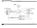
Master flow
DC2496
HIGH RESOLUTION
ANALOGUE TO DIGITAL
CONVERTER
COPYRIGHT
This manual is copyrighted 8 1999 by Drawmer Electronics, Ltd. With all rights reserved. Under copyright laws, no part of this publication may be
reproduced, transmitted, stored in a retrieval system or translated into any language in any form by any means, mechanical, optical, electronic,
recording, or otherwise, without the written permission of Drawmer Electronics Ltd
ONE YEAR LIMITED WARRANTY
Drawmer Electronics Ltd., warrants the Drawmer DC2496 high
resolution analogue to digital converter to conform substantially
to the specifications of this manual for a period of one year from
the original date of purchase when used in accordance with the
specifications detailed in this manual. In the case of a valid warranty claim, your sole and exclusive remedy and Drawmer’s entire
liability under any theory of liability will be to, at Drawmer=s discretion, repair or replace the product without charge, or, if not
possible, to refund the purchase price to you. This warranty is not
transferable. It applies only to the original purchaser of the product.
For warranty service please call your local Drawmer dealer. Alternatively call Drawmer Electronics Ltd. at +44 (0)1709 527574.
Then ship the defective product, with transportation and insurance charges pre-paid, to Drawmer Electronics Ltd., Coleman
Street, Parkgate, Rotherham, S62 6EL UK. Write the RA number
in large letters in a prominent position on the shipping box. Enclose your name, address, telephone number, copy of the original
sales invoice and a detailed description of the problem. Drawmer
will not accept responsibility for loss or damage during transit.
This warranty is void if the product has been damaged by misuse, modification or unauthorised repair.
THIS WARRANTY IS IN LIEU OF ALL WARRANTIES, WHETHER
ORAL OR WRITTEN, EXPRESSED, IMPLIED OR STATUTORY.
DRAWMER MAKES NO OTHER WARRANTY EITHER
EXPRESS OR IMPLIED, INCLUDING, WITHOUT LIMITATION,
ANY IMPLIED WARRANTIES OF MERCHANTABILITY,
FITNESS FOR A PARTICULAR PURPOSE, OR NONINFRINGEMENT. PURCHASER’S SOLE AND EXCLUSIVE
REMEDY UNDER THIS WARRANTY SHALL BE REPAIR OR
REPLACEMENT AS SPECIFIED HEREIN.
IN NO EVENT WILL DRAWMER ELECTRONICS LTD. BE LIABLE FOR ANY DIRECT, INDIRECT, SPECIAL, INCIDENTAL
OR CONSEQUENTIAL DAMAGES RESULTING FROM ANY
DEFECT IN THE PRODUCT, INCLUDING LOST PROFITS,
DAMAGE TO PROPERTY, AND, TO THE EXTENT PERMITTED BY LAW, DAMAGE FOR PERSONAL INJURY, EVEN IF
DRAWMER HAS BEEN ADVISED OF THE POSSIBILITY OF
SUCH DAMAGES.
Some states and specific countries do not allow the exclusion of
implied warranties or limitations on how long an implied warranty
may last, so the above limitations may not apply to you. This warranty gives you specific legal rights. You may have additional rights
that vary from state to state, and country to country.
In the interests of product development, Drawmer reserve the right to modify or improve specifications of this product at any time, without prior notice.
2
CONTENTS
Warranty . . . . . . . . . . . . . . . . . . . . . . . . . . . . . . . . . . . . . . . 2
Contents . . . . . . . . . . . . . . . . . . . . . . . . . . . . . . . . . . . . . . . 3
Safety Consideration . . . . . . . . . . . . . . . . . . . . . . . . . . . . . 4
Radio Frequencies Statement . . . . . . . . . . . . . . . . . . . . . . 4
Chapter 1 - DC2496 Hi Resolution A/D Converter
Introduction . . . . . . . . . . . . . . . . . . . . . . . . . . . . . . . . . . . . 5
Key Features . . . . . . . . . . . . . . . . . . . . . . . . . . . . . . . . . . . 5
Audio Connections . . . . . . . . . . . . . . . . . . . . . . . . . . . . . . . 6
Installation Precautions. . . . . . . . . . . . . . . . . . . . . . . . . . . . 6
Installation and Connection Guide . . . . . . . . . . . . . . . . . . . . 7
Chapter 2 - DC2496 Basic Effects
Front Panel Effects . . . . . . . . . . . . . . . . . . . . . . . . . . . . . 8
Chapter 3 - Operation
Setup System using Internal Sine Wave Generator
100Hz/1kHz Setup Tone . . . . . . . . . . . . . . . . . . . . . . . . . . . 10
1kHz Setup Tone at -40dB . . . . . . . . . . . . . . . . . . . . . . . . . 10
100Hz Setup Tone at -6dB . . . . . . . . . . . . . . . . . . . . . . . . . 10
Troubleshooting - 1kHz Setup Tone . . . . . . . . . . . . . . . . . . 10
96kHz 24 Bit Recording and Replay
96K 24 Bit A/D Input Recording . . . . . . . . . . . . . . . . . . . . . 12
96K 24 Bit A/D Input Replay from ADAT . . . . . . . . . . . . . . 12
96K 24 Bit A/D Input Replay from TDIF . . . . . . . . . . . . . . . 12
96K 24 Bit Replay from Hard Disk Recorder . . . . . . . . . . 12
Chapter 3 - Operation cont...
48kHz 24 Bit Recording and Replay
48K 24 Bit A/D Input Recording . . . . . . . . . . . . . . . . . . . . . 14
48K 24 Bit A/D Input Replay from ADAT . . . . . . . . . . . . . . 14
48K 24 Bit A/D Input Replay from TDIF . . . . . . . . . . . . . . . 14
48K 24 Bit Replay from Hard Disk Recorder . . . . . . . . . . 14
Multi-Track Copying
Copy ADAT Recording to TDIF. . . . . . . . . . . . . . . . . . . . . . 16
Copy TDIF Recording to ADAT. . . . . . . . . . . . . . . . . . . . . . 16
Copy TDIF/ADAT Hi- Res as Stereo Master. . . . . . . . . . . 16
Reduce 48K 24Bit Triple Tracks to 16 Bit Stereo. . . . . . . 16
Chapter 4 - Special Operation Notes
Record Hi-Res Bit Splitting Tracks to ADAT/TDIF. . . . . . . . . . . . 18
Special Digital Tape Recorder Play cases . . . . . . . . . . . . . . . . . . 18
Chapter 5 - DC2496 Information
Software Upgrades . . . . . . . . . . . . . . . . . . . . . . . . . . . . . . 19
Chapter 6 - General Information
If a fault develops . . . . . . . . . . . . . . . . . . . . . . . . . . . . . . . 20
Contacting Drawmer . . . . . . . . . . . . . . . . . . . . . . . . . . . . . 20
Chapter 7 - DC2496 Data
Specification . . . . . . . . . . . . . . . . . . . . . . . . . . . . . . . . . . . 21
Block Diagrams . . . . . . . . . . . . . . . . . . . . . . . . . . . . . . . . . 22
3
DRAWMER DC2496
For the USA
HIGH RESOLUTION ANALOGUE TO DIGITAL
CONVERTER
FEDERAL COMMUNICATIONS COMMISSION RADIO FREQUENCY INTERFERENCE STATEMENT
This equipment has been tested and found to comply with the limits for a
Class B digital device, pursuant to Part 15 of the FCC Rules. These limits
are designed to provide reasonable protection against harmful interference
in a residential installation. This equipment generates, uses and can radiate
radio frequency energy and, if not installed and used in accordance with the
instructions, may cause harmful interference to radio communications. However, there is no guarantee that interference will not occur in a particular
installation. If this equipment does cause interference to radio or television
reception, which can be determined by turning the equipment off an on, then
the user is encouraged to try to correct the interference by one or more of
the following measures:
Re-orient or relocate the receiving antenna.
Increase the separation between the equipment and the receiver.
Connect the equipment into an outlet on a circuit different from that
to which the receiver is connected.
Consult the dealer or an experienced radio/TV technician for help.
SAFETY CONSIDERATIONS
CAUTION - MAINS FUSE
TO REDUCE THE RISK OF FIRE REPLACE THE MAINS FUSE
ONLY WITH A FUSE THAT CONFORMS TO
EIC 127-2. 250 VOLT WORKING, TIME DELAY TYPE AND
BODY SIZE OF 20mm x 5mm.
THE MAINS INPUT FUSE MUST BE RATED AT T500mA.
CAUTION - MAINS CABLE
DO NOT ATTEMPT TO CHANGE OR TAMPER
WITH THE SUPPLIED MAINS CABLE.
CAUTION - SERVICING
DO NOT PERFORM ANY SERVICING. REFER ALL SERVICING
TO QUALIFIED SERVICE PERSONNEL.
Unauthorised changes or modification to this system can void the users=
authority to operate this equipment.
This equipment requires shielded interface cables in order to meet FCC
class B limit.
For Canada
WARNING
TO REDUCE THE RISK OF FIRE OR ELECTRIC SHOCK DO
NOT EXPOSE THIS EQUIPMENT TO RAIN OR MOISTURE.
CLASS B
NOTICE
This digital apparatus does not exceed the Class B limits for radio noise
emissions set out in the Radio Interference Regulations of the Canadian
Department of Communications.
CLASSE B
AVIS
Cet appareil numérique ne dépasse pas les limites de la classe B au niveau
des émissions de bruits radioélectriques fixés dans le Règlement des signaux
parasites par le ministère Canadien des Communications.
4
Chapter
CHAPTER 1
DRAWMER DC2496 HIGH RESOLUTION
ANALOGUE TO DIGITAL CONVERTER
INTRODUCTION
The Drawmer DC2496 is an extremely sophisticated, high resolution
analogue to digital converter designed for use in demanding recording and
broadcast applications. Both analogue (balanced XLR) and digital (AES/
EBU, S/PDIF, ADAT 8 Channel light pipe and TDIF 8 Channel) I/O is
provided as standard. The audio converters are 24-bit and the digital output
can be either 16, 18, 20, 22 or 24-bit at sample rates of up to 96kHz. Noise
shaped dithering is included and Word Clock input and output is available.
NOT JUST AN A/D CONVERTER BUT ALSO DIGITAL INTERFACE FOR
RECORDING FROM ONE UNIT TO ANOTHER - WITH A BACKUP AT
THE SAME TIME!
Why 96kHz?
Digital processing has until now been confined to 48kHz sampling frequency.
In order to achieve the required bandwidth for professional audio, a very severe
low pass filter at 23kHz is required to separate analogue signal frequencies
from the clock frequency otherwise unpleasant aliasing will occur. This requires
the use of a FIR digital filter which is part of the A/D and D/A converters.
Unfortunately these filters cause what is known as >time smear=, where short
transients are smeared over a longer time period giving loss of HF detail. At
96kHz sample frequency, the low pass filter is less severe and at twice the
frequency, so time smear is considerably reduced.
A second important consideration is the increased audio bandwidth up to
40kHz. This allows harmonics which extend above human hearing to be
generated and preserved. These harmonics, although not audible themselves,
make a contribution to the sound quality.
1
DC2496 HI RES A/D CONVERTER
Key Features
96k 24bit A/D with 130dB dynamic range and very low THD.
Simultaneously record 96k/48k 24bit stereo input to 48K (three) or 96K (six)
tracks to ADAT or TDIF 8 track digital tape recorder and stereo 48k 16bit
backup (to tracks 7/8) and record an independant backup copy at 48/44.1 20/
16bits to DAT (using internal Sample Rate Convertor)
Sample Rate Convertor with bit reduction and dither to reduce 96/88.2K 24bit
recordings to 48/44.1K 16/20bit for CD masters.
Built in 96/48K high quality D/A to monitor digital signals or record to analog
tape.
Dual time constant Stereo Limiter with variable time constants can apply up
to 18dB stereo gain to any input signal.
100dB range 64 element stereo signal meter with peak hold.
Selection of Noise shaped dither and bit rounding to reduce 96/48/44.1K
recordings to 22, 20, 18 or 16 bits.
Digitally copy 8 track stereo or Hi-Res ADAT/TDIF recordings to or from TDIF/
ADAT.
Auto identify Stereo or Hi-Res recordings upon ADAT or TDIF replay.
Inputs from A/D ADAT optical, TDIF, AES, SPDIF, Outputs to D/A ADAT
optical, TDIF, AES, SPDIF.
Seperate Digital Word Sync from D/A TDIF, ADAT, AES, SPDIF or BNC .
Rear panel show which sockets are active for easy hookup using Green (for
input signal) and Yellow (for word clock inputs) LEDs.
Built in 100Hz, 1kHz, 10kHz and dual sine wave generator (100Hz Left Ch,
1K Right Ch) sine tone at -40dB, -20dB and variable -24db to -6dB output
level to aid connection dificulties and troubleshooting.
Dual PLL for low jitter
5
Chapter
1
DC2496 HI RES A/D CONVERTER
AUDIO CONNECTIONS
Analogue Inputs
The inputs and outputs to the DC2496 are electronically balanced and would
normally be connected to your system via a patchbay. Should unbalanced
operation be required, simply ground pin 3 on the XLR connectors.
If earth loop hum problems are encountered, do not disconnect the mains
earth but instead, try disconnecting one end of the signal screen on the
cables connecting the DC2496 to the patchbay. If such measures are
necessary, balanced operation is recommended.
AES/EBU
Is via an XLR connector designed to be used with standard balanced
microphone cable (20 metres maximum), wired pin 1 screen, pin 2 and 3
balanced data, and the XLR shell connected to the chassis. Having many
short cables joined together is not advisable as each connector can cause
undesirable signal reflections.
The output socket fully conforms to the EMC standards; if the unit is to be
used where it may be exposed to high levels of disturbance, such as found
close to a TV or radio transmitter, it is suggested that the screen of the data
cable be connected to the chassis connection on the XLR type connector
rather than to pin 1.
If ground loop problems are encountered, never disconnect the mains ground,
but instead, try disconnecting the signal screen on one end of each cable
connecting the outputs.
S/PDIF
Is via a high quality RCA type phono jack where the data conforms to the
SonyJ PhillipsJ Digital InterFace format. Because this connector only
provides an unbalanced termination, the recommended maximum length
for this cable is 3 metres, even with very high quality cable.
Word Clock
For external clock synchronisation or when the DC2496 is providing the clock
to another source, this is carried out via the 50Ω BNC connector.
ADAT
Connect via an Optical Cable (Light Pipe) with a maximum recommended
length of three metres. The cable supports 8 channels at a 24 Bit word
resolution. The Drawmer DC2496 provides seperate ADAT input and output
as standard.
6
TDIF
Is via a 25 pin D connector. This is a unique cross-wired cable, supplied by
Tascam. It has 8 inputs, 8 outputs all at 24 Bit word resolution as well as
TDIF word clock in and out all in the one connector. The maximum
recommended length is three metres.
Note: When the TDIF D plug is inserted the main BNC Word Clock out is
shifted by 90 degrees fot TDIF use only.
INSTALLATION PRECAUTIONS
Should a fuse blow, replace it only with the same type and value as the one
fitted.
When installing the DC2496, ensure that it is allowed sufficient ventilation
and avoid mounting it next to excessively hot pieces of equipment or devices
emitting a strong magnetic field such as is often the case with power
amplifiers. If the unit is to be used in a mobile situation, it is strongly
recommended that the rear of the unit is supported in the carrying rack to
avoid bending the front panel rack mounting ‘ears’.
Should the unit require cleaning, use a damp cloth with a little liquid detergent;
do not use thinners or spirit cleaners as these may attack the finish.
Chapter
1
DC2496 HI RES A/D CONVERTER
INSTALLATION AND CONNECTION GUIDE
7
Chapter
2
DC2496 BASIC EFFECTS
BASIC EFFECTS
CHAPTER 2
Input Signal
Limiter
Word Resolution
Dither
INPUT SIGNAL shows the
selected input source. This signal
is also indicated on the rear panel
by lighting the selected signal
Green LED.
The WORD CLOCK must be set
to the appropriate source
otherwise clicks, pops or even
loud white noise may be heard.
When setting up for a new signal
source firstly select the mode for
RECORD or PLAY (each mode
has its own set of input, Limiter,
Word Res etc. settings)
The limiter will only have any effect when ‘DIGITAL
GAIN’ is set greater than 0dB.
There are several attack/decay settings:
use ‘SLOW’ for least intrusive signal leveling with
up to 18dB of gain,
‘MED’ to increase to perceived volume with up to
+12dB of gain,
‘FAST’ for transient capture.
Note: if more than +9dB of ‘DIGITAL GAIN’ is
applied then it is possible hear the limiter
pumping,
use ‘HOLD’ to normalise the signal to exactly 0dB.
Select ‘HOLD’, play the track using +18dB of
‘DIGITAL GAIN’ then rewind and the track will be
ready to play with its max peaks unlimited at 0dB.
Re-select the ‘HOLD’ LED to re-set the hold level.
The ‘LIMIT’ meter LED will remain lit when ‘HOLD’
is selected and the input signal has been limited,
until the ‘LIMITER’ button is pressed. The ‘LIMIT’
LED will also remain lit for up to 10 seconds as
the limiter releases when ‘SLOW’ and the input
signal has been severly limited.
WORD RESOLUTION defines the
number of bits per audio sample,
ie: Standard audio CD is 16bits.
H.F dither generally removes the
low level distortion on low signal
levels with the least noticable
noise.
M.F dither produces the lower
distortion with a slight increase
in noise over H.F dither
DUAL dither produces the lowest
distortion but still has much less
perceived noise than White noise
dither.
White noise is the standard dither
added to prevent distortion on low
level signals when the WORD
RESOLUTION of a signal is
reduced, ie. 24bit recording
reduced to 16bits. It offers poor
performance in terms of perceived
noise.
ALWAYS reduce to monitor
volume before changing the input
signal or word clock source to
prevent damage to ears or
speakers.
8
This must match the recording
medium otherwise ‘Truncation’
distortion will occur. Truncation
distortion cannot be removed after
recording by adding dither to a
truncated signal.
When word resolution is reduced
to less bits than the original then
dither must be added to mask the
distortion that is caused when the
bits are lost.
If the DC2496 A/D is 24bit
resolution, when reducing this to
16bits for a DAT recording
normally best results are obtained
with HF dither.
Chapter
2
Sample Rate / Ext Word Clock
Replay Track
Mode
SAMPLE RATE selects the required highly accurate
internal crystal controlled dual PLL clock signal. This
can be 44.1, 48, 88.2,96k or EXT which can use an
external Word Clock signal.
EXT WORD CLOCK selects the source for the word
clock (indicated by a yellow LED on the rear panel).
It must be within the range 30kHz to 100kHz. The
signal will be sent to the DC2496 dual PLL for clock
cleaning to reduce distortion that can be caused by
jitter on the clock signals.
The Front panel yellow ‘EXT WORK CLOCK’ LED will
flash quickly if a clock is unstable or will flash slowly
if clock not connected.
REPLAY TRACK is only lit when ADAT or TDIF
input signal has been selected.
The number of LEDs lit depends on the tracks
being replayed from the multitrack tape recorder:
Normal stereo signals light one LED allowing 4
pairs of stereo signals to be monitored.
When 2 LEDs are lit (only when the tape is
playing) then a Hi-Res triple track has been
detected which will be replayed as stereo output
of 24bits at 48kHz.
When 3 LEDs are lit then a 96 or 88.2kHz ‘Hex’
track has been detected which will be replayed
at 96kHz from the Main digital outputs and D/A
but 48Khz from the Sample Rate Converter digital
outputs and the Multitrack outputs.
If the replay track changes from normal 16/20
bit mode to Hi-Res mode there will be a short
burst of white noise for a couple of hundred mS.
This is due to tracks 3/4 which sound like 0dB
white noise being audible while the DC2496 auto
detects the Hi-Res mode.
RECORD/PLAY selects
between two sets of all
the other button
settings.
Ensure the correct Sample Rate & EXT WORD
CLOCK are selected otherwise a small amount of
distortion on the signal, regular click, pops or a
repeating ‘Zwang’ type sound may occur (this applies
to all digital equipment).
Note: after the sample rate has been changed, the A/
D will require an audio signal for 1 minute to settle
back to its full dynamic range.
Select this before
altering any other
parameter.
DC2496 BASIC EFFECTS
Digital Gain
GAIN of up to +18dB can
be applied.
Be aware that digital
distortion can occur
whenever gain is applied
therefore the Limiter should
be switched on (see
LIMITER section).
9
Chapter
OPERATION
3
Setup System using Internal Sine Wave Generator
CHAPTER 3
OPERATION
Use the internal sine wave generator to confirm output signals and to identify
left/right channels. A 100Hz, 1kHz or 10kHz internally generated sine wave at -40dB, -20dB or 26dB to -6dB variable will be sent to all outputs.
When the input signal button is pressed the setup tone stops.
FRONT PANEL
COMMENTS
SETUP TONE
ON
ON
LEVEL
dBu
- 4 0 - 2 0 Gain
OPERATION
FREQ
Hz
100Hz and 1kHz Setup Tone at
48kHz sample rate to All Outputs
A 100Hz tone at -20dB will be sent to all left
channels outputs.
LEVEL
dBu
FREQ
Hz
ON
- 4 0 - 2 0 Gain
SPDIF
100 1 K 10K
ON
ON
ON
10
LEVEL
dBu
- 4 0 - 2 0 Gain
LEVEL
dBu
- 4 0 - 2 0 Gain
FREQ
Hz
MED
ADAT
SLOW
100 1 K 10K
FREQ
Hz
100 1 K 10K
22 BIT
not
active
SPDIF
SAMPLE
RATE
EXTENDED
WORK CLOCK
REPLAY
TRACK
MODE
DIGITAL
GAIN
+9
EXT >
OFF
WHITE
DUAL
M.F.
44.1K
AES/SPDIF
BNC
48K
TDIF
88.2K
24 BIT
H.F.
96K
ADAT
as
required
as
required
as
required
as
required
HOLD
16 BIT
5,6
PLAY
RECO RD
3,4
+3
1,2
+15
0
not
active
as
required
+18
not
active
+9
EXT >
OFF
+12
7,8
+6
AES
FAST
TDIF
MED
ADAT
SLOW
A/D
22 BIT
not
active
SPDIF
18 BIT
20 BIT
OFF
WHITE
DUAL
M.F.
44.1K
AES/SPDIF
BNC
48K
TDIF
88.2K
24 BIT
H.F.
96K
ADAT
as
required
as
required
as
required
as
required
HOLD
16 BIT
5,6
PLAY
RECO RD
3,4
+3
1,2
+15
0
not
active
as
required
+18
not
active
+9
EXT >
OFF
+12
7,8
+6
AES
TDIF
FAST
MED
ADAT
22 BIT
OFF
all these leds are
off while setup
tone is generated
not
active
SPDIF
18 BIT
20 BIT
SLOW
A/D
Troubleshooting - 1kHz Setup
Tone will not be sent to any Outputs
AES external clock is selected but no AES
input is connected to the unit
Note the flashing AES / SPDIF Ext word
clock led.
16 BIT
18 BIT
20 BIT
OFF
all these leds are
off while setup
tone is generated
100Hz Setup Tone at -6dB
to All Outputs
A 100Hz tone at -6dB will be sent to all
outputs.
Use the Gain control to set the output level
from -26dB to -6dB.
HOLD
FAST
TDIF
all these leds are
off while setup
tone is generated
ON
FRONT PANEL
DITHER
WORD
RESOLUTION
+6
1kHz Setup Tone at -40dB
to All Outputs
A 1kHz tone at -40dB will be sent to all
outputs.
LIMITER
AES
A/D
100 1 K 10K
A 1kHz tone at -26dB will be sent to all right
channel outputs.
ON
INPUT
SIGNAL
WHITE
DUAL
M.F.
44.1K
AES/SPDIF
BNC
48K
TDIF
88.2K
24 BIT
H.F.
96K
ADAT
as
required
as
required
as
required
as
required
HOLD
16 BIT
5,6
+3
+15
PLAY
RECO RD
3,4
1,2
0
not
active
as
required
+18
Sine wave
ouptut level = -6dB
+9
EXT >
OFF
+12
7,8
+6
AES
FAST
TDIF
MED
ADAT
SLOW
A/D
all these leds are
off while setup
tone is generated
OFF
not
active
18 BIT
20 BIT
22 BIT
WHITE
DUAL
M.F.
24 BIT
H.F.
as
required
as
required
44.1K
48K
88.2K
96K
external word
clock
AES/SPDIF
BNC
TDIF
ADAT
AES/SPDIF
(led flashing)
+12
7,8
5,6
3,4
+3
1,2
not
active
+15
PLAY
RECO RD
0
as
required
+18
not
active
Chapter
WORD
CLOCK
REAR PANEL - BOTTOM ROW
MAIN DIGITAL OUTPUTS
DIGITAL I/O
SPDIF SPDIF/AES
AES
ADAT
TDIF-1
ADAT
TOGGLE
DIGITAL INPUTS
WORD SPDIF
CLOCK
AES
WORD
CLOCK
OPERATION
3
REAR PANEL - TOP ROW
AUX DIGITAL OUTPUTS
ANALOGUE OUTPUTS
SPDIF SPDIF/AES
AES
SAMPLE WORD
LEFT
MAX
RIGHT
TOGGLE
RATE
RES
LEVEL
ANALOGUE INPUTS
LEFT
MAX
RIGHT
LEVEL
16 Bit
20 Bit
word clock
Not
output
connected
AES
sine wave
output
sine
output on
all 8
tracks
sine wave will be output
on all 8 tracks
Not
active
Not
active
Not
active
Not
active
word
clock
output
not
used
AES
sine
wave
input
48K
16Bit
sine wave
output
+21dBu
sine wave
max output
output
signal
level
Not
Active
Not
Active
Not
Active
sine wave
output
+21dBu
sine wave
max output
output
signal
level
Not
Active
Not
Active
Not
Acitive
sine wave
output
+21dBu
sine wave
max output
output
signal
level
Not
Acitive
Not
Acitive
Not
Acitive
+21dBu
max output
signal
level
Not
Acitive
Not
Acitive?
Not
Acitive
16 Bit
20 Bit
word clock
Not
output
connected
AES
sine wave
output
sine
output on
all 8
tracks
sine wave will be output
on all 8 tracks
Not
active
word
clock
input
Not
active
Not
active
word
clock
output
sine
wave
ouptut
SPDIF
Not
used
48K
16Bit
16 Bit
20 Bit
to Tascam
Not
word clock connected
in
AES
sine wave
output
sine
output on
all 8
tracks
sine wave will be output
on all 8 tracks
Not
active
Not
active
Not
active
Not
active
word
clock
output
sine
wave
ouptut
SPDIF
Not
used
48K
16Bit
16 Bit
20 Bit
no
output
no
output
AES
no
output
no
output
no
output
Not
active
Not
active
Not
active
Ext clock
source is
not
connected
word
clock
output
Not
active
SPDIF
Not
active
48K
16Bit
no
output
no
output
11
Chapter
3
OPERATION
96K 24Bit Recording and Replay
OPERATION
96K 24Bit A/D conversion with monitor speakers recording and replaying, 8 Track
digital tape recorders, DAT and 24Bit 96K hard disk recorder, also recording 44.1K 16 Bit to
Mini-disc, all simultaneously.
COMMENTS
1) Ensure that the A/D input signal does not light
the overload leds - analogue clipping will occur.
Reduce the mixer output level as required. Apply
DC2496 digital gain with limiter to allow more A/
D input headroom whilst preserving 0dBFS
digital level.
2) If the peak noise level from the mixing desk is
above -100dB then the bottom leds of the meter
will remain lit.
3) If the mixer has a -10dBu output level then the
analogue input switch should be pressed (+4dBu
max input signal level).
4) To ensure a 0dBFS digital signal level add a few
dB’s of digital gain and set the limiter to fast.
5) If digital gain is applied with the limiter off then
unpleasant digital distortion can occur on peaks.
6) When the DC2496 is running at 96K or 88.2K
and the main digital output is connected to a
48K digital input no signal will be received!
7) The A/D noise floor is 6dB higher at 96/88.2K
that at 48/44.1K.
OPERATION
96K 24 Bit A/D Input Recording
Record a stereo signal as hex (6) tracks 1,2,3,4,5,6 on an
ADAT or Tascam 16/20Bit digital multi-track tape
recorder - and 7,8 stereo pair as 48K backup if required.
ADAT machines must be set to EXT Clock.
Tascam machines must be set to WORD clock.
and a BNC lead from DC2496 main word clock to
Tascam Word Clock in.
Replay hex (6) tracks 1,2,3,4,5,6,
or 7,8 48K stereo pair.
HOLD
MED
ADAT
SLOW
A/D
16 BIT
SAMPLE
RATE
EXTENDED
WORK CLOCK
REPLAY
TRACK
MODE
DIGITAL
GAIN
+9
EXT >
OFF
18 BIT
20 BIT
22 BIT
Use as
required
SPDIF
DUAL
AES/SPDIF
BNC
48K
TDIF
ADAT
96K
High Frequency
Noise shaped
dither
16 BIT
44.1K
88.2K
H.F.
24 bit
bit splitting mode
to record
6 tracks
HOLD
WHITE
M.F.
24 BIT
OFF
XLR balanced
inputs.
96K internal
sample rate
none
5,6
PLAY
RECO RD
3,4
+3
1,2
+15
0
none
SELECT THIS
RECORD
LED FIRST
+18
0 dB
If gain is applied
limiter
must be used
+9
EXT >
OFF
+12
7,8
+6
AES
FAST
TDIF
MED
ADAT
SLOW
18 BIT
20 BIT
22 BIT
Use as
required
SPDIF
DUAL
AES/SPDIF
BNC
48K
TDIF
ADAT
96K
High Frequency
Noise shaped
dither
16 BIT
44.1K
88.2K
H.F.
24 bit
stereo mode
HOLD
WHITE
M.F.
24 BIT
OFF
Light Pipe ADAT
optical in
5,6
PLAY
RECO RD
3,4
+3
1,2
+15
0
96K or 88.2K lit
ADAT external Lit when hex track
whenhex
optical input word
recording is
trackrecording is
clock
replayed
replayed
SELECT THIS
PLAY
LED FIRST
+18
6 dB
of gain with limit
use as required
+9
EXT >
OFF
+12
7,8
+6
AES
TDIF
ADAT
18 BIT
20 BIT
SLOW
22 BIT
Use as
required
SPDIF
DUAL
AES/SPDIF
BNC
48K
TDIF
ADAT
96K
High Frequency
Noise shaped
dither
16 BIT
44.1K
88.2K
H.F.
24 bit
stereo mode
HOLD
WHITE
M.F.
24 BIT
OFF
TDIF digital
input fron
25 pin D plug
96K 24 Bit Replay from Hard Disk
recorder or other AES Digital Input
FAST
MED
A/D
Monitor on D/A whilst recording to mini-disc,
ADAT and TDIF similtaneously
(All recording devices must use
external word clock)
FAST
TDIF
96K 24 Bit A/D Input Replay
from TDIF i.e. DA-88
Tascam machines must be set to INT clock.
FRONT PANEL
DITHER
WORD
RESOLUTION
+6
A/D
ADAT must be set to INT Clock.
9) When the TDIF plug is inserted into the rear of
the DC2496 the main digital output word clock
BNC socket will be at 44.1K when recording at
88.2K and 48K when recording at 96K - and only
suitable for TDIF word sync input.
12
SPDIF
96K 24 Bit A/D Input
Replay from ADAT
Replay hex (6) tracks 1,2,3,4,5,6,
or 7,8 48K stereo pair.
11) ADAT and TDIF recordings will always be at
44.1/48K when recording 88.2/96K A/D or digital
input signals.
LIMITER
AES
8) When recording hex (6) tracks, tracks 7 and 8
will only monitor at 16Bit resolution from the
Sample Rate Converter (upper) digital outputs.
10) Always reduce monitor volume when selecting
different word clocks or sample rates.
INPUT
SIGNAL
96K or 88.2K lit
whenhex
trackrecording is
replayed
TDIF external
25 pin D plug
word clock
5,6
+3
+15
PLAY
RECO RD
3,4
1,2
0
Lit when hex track
recording is
replayed
SELECT THIS
PLAY
LED FIRST
FAST
+9
EXT >
OFF
TDIF
MED
ADAT
SLOW
A/D
AES (XLR)
digital input
OFF
Use as
required
18 BIT
20 BIT
22 BIT
24 BIT
24 bit
stereo mode
WHITE
DUAL
M.F.
H.F.
High Frequency
Noise shaped
dither
44.1K
48K
88.2K
96K
96K or 88.2K lit
depending on
replay sample
rate
+18
6 dB
of gain with limit
use as required
+6
AES
+12
7,8
AES/SPDIF
BNC
TDIF
ADAT
AES (XLR)
word clock
+12
7,8
5,6
3,4
+3
1,2
Not
Active
+15
PLAY
RECO RD
0
SELECT THIS
PLAY
LED FIRST
+18
6 dB
of gain with limit
use as required
Chapter
WORD
CLOCK
REAR PANEL - BOTTOM ROW
MAIN DIGITAL OUTPUTS
DIGITAL I/O
SPDIF SPDIF/AES
AES
ADAT
TDIF-1
ADAT
TOGGLE
DIGITAL INPUTS
WORD SPDIF
CLOCK
AES
WORD
CLOCK
OPERATION
3
REAR PANEL - TOP ROW
AUX DIGITAL OUTPUTS
ANALOGUE OUTPUTS
SPDIF SPDIF/AES
AES
SAMPLE WORD
LEFT
MAX
RIGHT
TOGGLE
RATE
RES
LEVEL
ANALOGUE INPUTS
LEFT
MAX
RIGHT
LEVEL
16 Bit
20 Bit
to Tascam
Not
word clock connected
in
AES
to Hard
Disk
Recorder
to ADAT
Recorder
to Tascam Recorder
Not
active
Not
active
Not
active
Not
active
Not
used
to
Mini-disc
recorder
SPDIF
Not
used
44.1K
16Bit
to
Monitor
Amplifier
+21dBu
max output
signal
level
to
Monitor
Amplifier
from
+21dBu
from
Monitor
max output
Monitor
Desk output
signal
Desk output
level
to
Monitor
Amplifier
+21dBu
max output
signal
level
to
Monitor
Amplifier
Not
Acitive
Not
Acitive
Not
Acitive
to
Monitor
Amplifier
+21dBu
max output
signal
level
to
Monitor
Amplifier
Not
Acitive
Not
Acitive
Not
Acitive
to
Monitor
Amplifier
+21dBu
max output
signal
level
to
Monitor
Amplifier
Not
Acitive
Not
Acitive
Not
Acitive
16 Bit
20 Bit
to Tascam
Not
word clock connected
in
AES
to Hard
Disk
Recorder
to ADAT
Recorder
to Tascam TDIF
digital I/O
Copy ADAT recording to
Tascam
Optical
light pipe
from ADAT
digital out
Not
active
Not
active
Not
active
Not
used
to
Mini-disc
recorder
SPDIF
Not
used
44.1K
16Bit
16 Bit
20 Bit
to Tascam
Not
word clock connected
in
AES
to Hard
Disk
Recorder
copy to
ADAT
digital
input
25 pin D plug from
Tascam digital I/O
Not
active
Not
active
Not
active
Not
active
Not
used
to
Mini-disc
recorder
SPDIF
Not
used
44.1K
16Bit
16 Bit
20 Bit
Not
to Tascam
word clock connected
in
AES
to Hard
Disk
Recorder
copy to
ADAT as
hex tracks
at 48K
to Tascam TDIF digital I/O
Copy hard disk recording
to Tascam as hex tracks
at 48K
Not
active
Not
active
Not
active
Diital input
from hard
disk recorder
Not
used
to
Mini-disc
recorder
SPDIF
Not
used
44.1K
16Bit
13
Chapter
3
OPERATION
48K 24Bit Recording and Replay
OPERATION
48K 24Bit A/D conversion with monitor speakers recording and replaying, 8 Track
digital tape recorders, DAT and 24Bit 48K hard disk recorder, also recording 44.1K 16 Bit to
Mini-disc, all simultaneously.
COMMENTS
1) Ensure that the A/D input signal does not light
the overload leds - analogue clipping will occur.
Reduce the mixer output level as required. Apply
DC2496 digital gain with limiter to allow more A/
D input headroom whilst preserving 0dBFS
digital level.
2) If the peak noise level from the mixing desk is
above -100dB then the bottom leds of the meter
will remain lit.
3) If the mixer has a -10dBu output level then the
analogue input switch should be pressed (+4dBu
max input signal level).
4) To ensure a 0dBFS digital signal level add a few
dB’s of digital gain and set the limiter to fast.
5) If digital gain is applied with the limiter off then
unpleasant digital distortion can occur on peaks.
6) When recording triple (3) tracks, tracks 7 and 8
will only monitor at 16Bit resolution from the
Sample Rate Converter (upper) digital outputs.
7) When the TDIF plug is inserted into the rear of
the DC2496 the main digital output word clock
BNC is only suitable for TDIF word sync input.
8) When monitoring using the Slave Digital Output
white noise bursts at 0dB may be heard when
changing sample rate.
9) Always reduce monitor volume when selecting
different word clocks or sample rates.
OPERATION
INPUT
SIGNAL
48K 24 Bit A/D Input Recording
Record a stereo signal on triple (3) tracks either as
tracks 1,2,3 or 4,5,6 or both on an ADAT or Tascam 16/
20Bit digital multi-track tape recorder - and 7,8 stereo
pair as a backup if required.
ADAT machines must be set to EXT Clock.
Tascam machines must be set to WORD clock, and a
BNC lead from DC2496 main word clock to Tascam
Word Clock in.
SPDIF
14
FAST
TDIF
MED
ADAT
SLOW
A/D
EXTENDED
WORK CLOCK
REPLAY
TRACK
MODE
DIGITAL
GAIN
+9
EXT >
OFF
18 BIT
20 BIT
22 BIT
Use as
required
SPDIF
DUAL
AES/SPDIF
BNC
48K
TDIF
ADAT
96K
High Frequency
Noise shaped
dither
16 BIT
44.1K
88.2K
H.F.
24 bit
bit splitting mode
to record
6 tracks
HOLD
WHITE
M.F.
24 BIT
OFF
XLR balanced
inputs.
48K internal
sample rate
none
5,6
PLAY
RECO RD
3,4
+3
1,2
+15
0
none
SELECT THIS
RECORD
LED FIRST
+18
0 dB
If gain is applied
limiter
must be used
+9
EXT >
OFF
+12
7,8
+6
AES
FAST
TDIF
MED
ADAT
SLOW
A/D
18 BIT
20 BIT
22 BIT
Use as
required
SPDIF
DUAL
AES/SPDIF
BNC
48K
TDIF
ADAT
96K
High Frequency
Noise shaped
dither
16 BIT
44.1K
88.2K
H.F.
24 bit
stereo mode
HOLD
WHITE
M.F.
24 BIT
OFF
Light Pipe ADAT
optical in
5,6
PLAY
RECO RD
3,4
+3
1,2
+15
0
96K or 88.2K lit
ADAT external Lit when hex track
whenhex
optical input word
recording is
trackrecording is
clock
replayed
replayed
SELECT THIS
PLAY
LED FIRST
+18
6 dB
of gain with limit
use as required
+9
EXT >
OFF
+12
7,8
+6
AES
TDIF
FAST
MED
ADAT
22 BIT
Use as
required
SPDIF
DUAL
AES/SPDIF
BNC
48K
TDIF
ADAT
96K
High Frequency
Noise shaped
dither
16 BIT
44.1K
88.2K
H.F.
24 bit
stereo mode
HOLD
WHITE
M.F.
24 BIT
OFF
TDIF digital
input fron
25 pin D plug
18 BIT
20 BIT
SLOW
A/D
48K 24 Bit Replay from Hard Disk
recorder or other AES Digital Input
Monitor on D/A whilst recording to mini-disc,
ADAT and TDIF similtaneously
(All recording devices must use
external word clock)
16 BIT
SAMPLE
RATE
+6
48K 24 Bit A/D Input Replay
from TDIF i.e. DA-88
Replay triple (3) tracks 1,2,3 or 4,5,6,
or tracks 7,8 stereo pair.
Tascam must be set to INT Clock.
There will be a short burst of white noise at 0dB if a
replay track changes from normal 16/20 Bit mode to
High-Res mode whilst replaying.
FRONT PANEL
DITHER
WORD
RESOLUTION
HOLD
AES
48K 24 Bit A/D Input
Replay from ADAT
Replay triple (3) tracks 1,2,3 or 4,5,6,
or tracks 7,8 stereo pair.
ADAT must be set to INT Clock.
There will be a short burst of white noise at 0dB if a
replay track changes from normal 16/20 Bit mode to
High-Res mode whilst replaying.
LIMITER
96K or 88.2K lit
whenhex
trackrecording is
replayed
TDIF external
25 pin D plug
word clock
5,6
+3
+15
PLAY
RECO RD
3,4
1,2
0
Lit when hex track
recording is
replayed
SELECT THIS
PLAY
LED FIRST
FAST
+9
EXT >
OFF
TDIF
MED
ADAT
SLOW
A/D
AES (XLR)
digital input
OFF
Use as
required
18 BIT
20 BIT
22 BIT
24 BIT
24 bit
stereo mode
WHITE
DUAL
M.F.
H.F.
High Frequency
Noise shaped
dither
44.1K
48K
88.2K
96K
96K or 88.2K lit
depending on
replay sample
rate
+18
6 dB
of gain with limit
use as required
+6
AES
+12
7,8
AES/SPDIF
BNC
TDIF
ADAT
AES (XLR)
word clock
+12
7,8
5,6
3,4
+3
1,2
Not
Active
+15
PLAY
RECO RD
0
SELECT THIS
PLAY
LED FIRST
+18
6 dB
of gain with limit
use as required
Chapter
WORD
CLOCK
REAR PANEL - BOTTOM ROW
MAIN DIGITAL OUTPUTS
DIGITAL I/O
SPDIF SPDIF/AES
AES
ADAT
TDIF-1
ADAT
TOGGLE
DIGITAL INPUTS
WORD SPDIF
CLOCK
AES
WORD
CLOCK
OPERATION
3
REAR PANEL - TOP ROW
AUX DIGITAL OUTPUTS
ANALOGUE OUTPUTS
SPDIF SPDIF/AES
AES
SAMPLE WORD
LEFT
MAX
RIGHT
TOGGLE
RATE
RES
LEVEL
ANALOGUE INPUTS
LEFT
MAX
RIGHT
LEVEL
16 Bit
20 Bit
to Tascam
Not
word clock connected
in
AES
to Hard
Disk
Recorder
to ADAT
Recorder
to Tascam Recorder
Not
active
Not
active
Not
active
Not
active
Not
used
to
Mini-disc
recorder
SPDIF
Not
used
44.1K
16Bit
to
Monitor
Amplifier
+21dBu
max output
signal
level
to
Monitor
Amplifier
from
+21dBu
from
Monitor
max output
Monitor
Desk output
signal
Desk output
level
to
Monitor
Amplifier
+21dBu
max output
signal
level
to
Monitor
Amplifier
Not
Acitive
Not
Acitive
Not
Acitive
to
Monitor
Amplifier
+21dBu
max output
signal
level
to
Monitor
Amplifier
Not
Acitive
Not
Acitive
Not
Acitive
to
Monitor
Amplifier
+21dBu
max output
signal
level
to
Monitor
Amplifier
Not
Acitive
Not
Acitive
Not
Acitive
16 Bit
20 Bit
to Tascam
Not
word clock connected
in
AES
to Hard
Disk
Recorder
to ADAT
Recorder
to Tascam TDIF
digital I/O
Copy ADAT recording to
Tascam
Optical
light pipe
from ADAT
digital out
Not
active
Not
active
Not
active
Not
used
to
Mini-disc
recorder
SPDIF
Not
used
44.1K
16Bit
16 Bit
20 Bit
to Tascam
Not
word clock connected
in
AES
to Hard
Disk
Recorder
copy to
ADAT
digital
input
25 pin D plug from
Tascam digital I/O
Not
active
Not
active
Not
active
Not
active
Not
used
to
Mini-disc
recorder
SPDIF
Not
used
44.1K
16Bit
16 Bit
20 Bit
Not
to Tascam
word clock connected
in
AES
to Hard
Disk
Recorder
copy to
to Tascam TDIF digital I/O
Copy hard disk recording
ADAT as
to Tascam as triple tracks
triple
at 48K
tracks 48K
Not
active
Not
active
Not
active
Diital input
from hard
disk recorder
Not
used
to
Mini-disc
recorder
SPDIF
Not
used
44.1K
16Bit
15
Chapter
3
OPERATION
Multi-Track Copy
OPERATION
Digitally copy ADAT to TDIF or TDIF to ADAT 44.1/48K or 88.2/96K recordings.
Also reduce 48K 24Bit triple tracks to 48K 16 Bit stereo with optimum dither, without using
sample rate conversion.
COMMENTS
1) When the TDIF plug is inserted into the rear of
the DC2496 the main digital output word clock
BNC is only suitable for TDIF word sync input.
2) If digital gain is applied with the limiter off then
unpleasant digital distortion can occur on peaks.
3) When monitoring using the Slave Digital Output
white noise bursts at 0dB may be heard when
changing sample rate.
OPERATION
INPUT
SIGNAL
Copy ADAT Recording to TDIF
Make a digital copy of normal stereo tracks
or hi-res 48K triple or 96K hex tracks.
Set ADAT to INT Clock.
Set TDIF to WORD Clock and Digital Input.
SPDIF
TDIF
MED
ADAT
SLOW
A/D
Reduce a hex or triple track 96/48K 24 Bit
recording to 48K 16 Bit with optimum noise
shaped dither on tracks 7,8 slave and main
outputs.
22 BIT
DUAL
REPLAY
TRACK
MODE
DIGITAL
GAIN
+9
AES/SPDIF
BNC
48K
TDIF
ADAT
96K
only effects D/A
and main digital
outputs.
16 BIT
44.1K
88.2K
H.F.
only effects D/A
and main digital
outputs.
HOLD
WHITE
M.F.
24 BIT
only effects D/A
and main digital
outputs.
SPDIF
Select EXT
44.1/48K Led will
light depending
on recording
ADAT optical
word clock
5,6
PLAY
RECO RD
3,4
+3
1,2
+15
0
effects D/A, main
digital outputs
and aux digital
outputs.
SELECT THIS
RECORD
LED FIRST
+18
only effects D/A and
main digital outputs
+9
EXT >
OFF
+12
7,8
+6
FAST
TDIF
MED
ADAT
SLOW
A/D
18 BIT
20 BIT
22 BIT
only effects D/A
and main digital
outputs.
SPDIF
DUAL
AES/SPDIF
BNC
48K
TDIF
ADAT
96K
only effects D/A
and main digital
outputs.
16 BIT
44.1K
88.2K
H.F.
only effects D/A
and main digital
outputs.
HOLD
WHITE
M.F.
24 BIT
OFF
TDIF 25 pin D
plug input
Select EXT
44.1/48K Led will
light depending
on recording
TDIF external 25
pin D plug
word sync
5,6
PLAY
RECO RD
3,4
+3
1,2
+15
0
effects D/A, main
digital outputs
and aux digital
outputs.
SELECT THIS
RECORD
LED FIRST
+18
only effects D/A and
main digital outputs
+9
EXT >
OFF
+12
7,8
+6
AES
TDIF
FAST
MED
ADAT
22 BIT
Use as
required
SPDIF
DUAL
AES/SPDIF
BNC
48K
TDIF
ADAT
96K
High Frequency
Noise shaped
dither
16 BIT
44.1K
88.2K
H.F.
24 bit
stereo mode
HOLD
WHITE
M.F.
24 BIT
OFF
TDIF digital
input fron
25 pin D plug
18 BIT
20 BIT
SLOW
A/D
Reduce 48K 24Bit triple tracks to
16 Bit stereo.
Replay a ADAT or TDIF triple track reduced
to 16 Bit stereo.
EXTENDED
WORK CLOCK
EXT >
OFF
18 BIT
20 BIT
OFF
ADAT optical
input
Copy TDIF or ADAT Hi-Res Recording
to tracks 7,8 as stereo master
Select EXT
44.1/48K Led will
light depending
on recording
TDIF external
25 pin D plug
word clock
FAST
5,6
+3
+15
PLAY
RECO RD
3,4
1,2
0
Two leds will light
for triple track
replay - three for
hex
SELECT THIS
PLAY
LED FIRST
TDIF
MED
ADAT
SLOW
A/D
OFF
Use as
required
20 BIT
22 BIT
24 BIT
16 Bit
WHITE
DUAL
M.F.
H.F.
High Frequency
Noise shaped
dither
44.1K
48K
88.2K
96K
Select EXT
44.1/48K Led will
light depending
on recording
+18
3 dB
of gain with limit
use as required
+9
EXT >
OFF
18 BIT
+12
7,8
+6
AES
Select TDIF or
ADAT input as
required
16
FAST
AES
Set TDIF to WORD Clock.
Set ADAT to DIG Clock and Digital Input.
16 BIT
SAMPLE
RATE
+6
Copy TDIF to ADAT
Make a digital copy of normal stereo tracks
or hi-res 48K triple or 96K hex tracks.
FRONT PANEL
DITHER
WORD
RESOLUTION
HOLD
AES
4) Always reduce monitor volume when selecting
different word clocks or sample rates.
5) Triple and Hex Tracks (tracks 1 to 6) can be
digitally copied in the same way as normal
stereo recording.
Tracks 7 & 8 will be a stereo processed signal
with gain limit and dither.
LIMITER
AES/SPDIF
BNC
TDIF
ADAT
Select as
required
+12
7,8
5,6
3,4
+3
1,2
Two leds will light
for triple track
replay is detected
+15
PLAY
RECO RD
0
SELECT THIS
PLAY
LED FIRST
+18
3 dB
of gain with limit
use as required
Chapter
WORD
CLOCK
REAR PANEL - BOTTOM ROW
MAIN DIGITAL OUTPUTS
DIGITAL I/O
SPDIF SPDIF/AES
AES
ADAT
TDIF-1
ADAT
TOGGLE
DIGITAL INPUTS
WORD SPDIF
CLOCK
AES
WORD
CLOCK
OPERATION
3
REAR PANEL - TOP ROW
AUX DIGITAL OUTPUTS
ANALOGUE OUTPUTS
SPDIF SPDIF/AES
AES
SAMPLE WORD
LEFT
MAX
RIGHT
TOGGLE
RATE
RES
LEVEL
ANALOGUE INPUTS
LEFT
MAX
RIGHT
LEVEL
16 Bit
20 Bit
to Tascam
Not
word clock connected
in
AES
use
if
required
not
active
to Tascam Recorder
ADAT
optical
input &
word clock
Not
active
Not
active
Not
active
Not
used
to
Mini-disc
recorder
SPDIF
Not
used
44.1K
16Bit
to
Monitor
Amplifier
+21dBu
max output
signal
level
to
Monitor
Amplifier
Not
Active
Not
Active
Not
Active
to
Monitor
Amplifier
+21dBu
max output
signal
level
to
Monitor
Amplifier
Not
Acitive
Not
Acitive
Not
Acitive
to
Monitor
Amplifier
+21dBu
max output
signal
level
to
Monitor
Amplifier
Not
Acitive
Not
Acitive
Not
Acitive
to
Monitor
Amplifier
+21dBu
max output
signal
level
to
Monitor
Amplifier
Not
Acitive
Not
Acitive
Not
Acitive
16 Bit
20 Bit
to Tascam
Not
word clock connected
in
AES
use
if
required
Optical
light pipe
to ADAT
digital in
to Tascam TDIF
digital I/O
Not
active
Not
active
Not
active
Not
active
Not
used
to
Mini-disc
recorder
SPDIF
Not
used
44.1K
16Bit
16 Bit
20 Bit
to Tascam
Not
word clock connected
in
AES
use
if
required
copy to
ADAT
digital
input
25 pin D plug from
Tascam digital I/O
light pipe
from ADAT
digital
output
Not
active
Not
active
Not
active
Not
used
to
Mini-disc
recorder
SPDIF
16Bit
Not
used
16 Bit
20 Bit
Not
to Tascam
word clock connected
in
AES
use
if
required
copy to
ADAT
digital
input
25 pin D plug
Tascam digital I/O
light pipe
from ADAT
digital
output
Not
active
Not
active
Not
active
Not
used
to
Mini-disc
recorder
SPDIF
—
44.1K
16Bit
17
Chapter
4
SPECIAL OPERATION NOTES
CHAPTER 4
HELPFULL HINTS
Recording Hi-Resolution ‘Bit splitting’ tracks on a
Digital Tape Recorder (ADAT or TDIF)
When recording Triple (48k) or Hex (96k) Hi-Resolution tracks to tape the
SRC (upper) AES & SPDIF digital outputs will monitor tracks 7/8 @ 20 or
16bit resolution depending on the rear panel push switch.
When TDIF ‘D’ plug is inserted the DC2496 BNC Word Clock output will be
phase shifted by 90 degrees at a rated 44.1k @ 88.2k and 48k @ 96khz.
This is the clock for TDIF Word Sync.
When using A/D, ADAT or TDIF as the input signal and SAMPLE RATE is
set to EXT with AES/SPDIF then the DC2496 will get its EXT word clock
from the AES digital input (XLR socket), not the SPDIF digital input socket.
The main (lower) SPDIF and AES output sockets both support 88.1 and
96K 24bit signals if selected on the front panel. The EXT SPDIF word clock
input is only available when SPDIF input signal is also selected.
The Sample Rate Converted AES & SPDIF output sockets are rounded to
16/20bits and HF dither added regardless of front panel settings according
to the rear panel switch.
The ‘Setup tone’ frequency will only be accurate to a few percent of its
correct value when an EXT clock source is used.
The Rear panel ‘Green audio signals OK’ LEDs are lit when the PLL is
locked and signals are output.
ADAT and TDIF track outputs will always be at 44.12/48Khz even if A/D or
Digital input is at 88.2 or 96K
There are two Hi-Resolution recording modes:
Triple (3) track 24bit 44.1 or 48Khz on either or both tracks 123 or 456, or,
Hex (6) track 24bit 88.2 or 96Khz on tracks 123456.
Both triple and hex track modes also have a stereo backup 16bit 44.1 or
48k recording on tracks 7/8
When recording a 48/44.1K Hi-Res triple track it is prefferable to use tracks
4,5,6.
18
If tracks 123 only are recorded then there noise will be heard when
monitoring tracks 5,6. This is correct and is the ‘Remainder’ track of the HiRes signal.
If track triple 4,5,6 is recorded or both sets of Triple tracks then this noise
will not be heard.
Special Digital Tape Recorder (ADAT or TDIF) Play
cases:
When replaying a normal ADAT or TDIF recording, all 8 tracks will be
directly copied to the 8 TDIF and ADAT output tracks.
Limiter, Gain, Word resolution, dither etc will not modify the 8 track signals.
The Main digital output will have Gain, Limit etc. and will monitor the
selected replay track LEDs.
The 48/44.1Khz SRC digital output will exactly monitor the selected replay
track LEDs (without Gain, Limiter etc).
When replaying a Hi resolution triple or hex track recording (made when
both 24 and 16 bit WORD RESOLUTION LEDs are lit) the Sample Rate
Convertor digital AES/SPDIF, the Main AES/SPDIF digital output and TDIF
and ADAt track outputs 7/8 will replay the stereo signal from the tracks
shown by the REPLAY TRACK LEDs. Gain, limiter, Bit rounding & dither can
all be applied.
The TDIF and ADAT output tracks 1 thru 6 will be an exact bit copy of the
triple or hex track Hi-res recording.
For best results when reducing a 96K 24bit recording to 44.1 @ 16 bits
leave the front panel LED set to 24bits and reduce the signal to 16bits @
44.1Khz on the SRC rear panel grey push switches.
The DC2496 cannot record or play normal stereo signals @ 96k to ADAT or
TDIF. You must select the WORD RESOLUTION as 2 LED (16 and 24) bit
spliting mode and Sample Rate as 44.1/48K.
Up to 4 x DC2496 can be used to simultanious record 48K 24bit signals (if
the recorder alows) to TDIF using a special splitter lead. The Word Clock
must be EXT TDIF on the DC2496’s with the TDIF machine providing the
Word Clock. This cannot be done using ADAT light pipe
Several DC2496 units can be synchronised to sample accuracy (better
than 0.2uS) by setting the master unit SAMPLE RATE to Internal clock 96/
88.2/48/44.1 FS then setting the other units as EXT BNC word clock
slaves.
Chapter
CHAPTER 5
DC2496 INFORMATION
SOFTWARE UPGRADES
Periodically there may be additions to the DC2496 software that will be
made available.
In order to carry out a software upgrade to the DC2496 the following parts
will be required:
486 or better PC computer running Win95 or late.
Cable - RS232 9 pin to RS232 9 pin. Connected to Com 1 on the
P.C. and into the RS232 port on the rear of the DC2496.
DRAWMER ‘Masterflow DC2496 upgrade’ software - available free
from our web site.
The ‘Masterflow Upgrade’ programme can be obtained by two methods:
1 Contact your main dealer to receive the upgrade on 2 x floppy disks.
2 Download the new version of software from the internet.
Website address
www.drawmer.co.uk
To Install the software onto the PC
1 Press START
Select RUN
Choose setup.exe
5
DC2496 INFORMATION
Once the software has been obtained the unit can be upgraded. This is
achieved by the following method:
Plug the RS232 cable into the Com 1 port on your PC.
Connect the other end of the RS232 into the RS232 slot on the rear
of the DC2496.
Click START.
Select PROGRAMMES.
Click on the Upgrade icon.
Wait a few seconds until the DC2496 unit has been recognised.
The installed software will be compared and if required the unit will
be upgraded. (This will take approximately 2 minutes)
A Screen message will indicate the software version number.
Once the software has been upgraded, the latest ‘Features’ notes
will be displayed and also the ‘Reset factory patches’ button.
Click the ‘Reset Factory Patches’ button to
overwrite all factory patches with the ones
contained in the latest software
Click ‘EXIT’ to leave the upgrade programme.
2 Download the latest software
upgrade e.g.:’DC2496 1v02.UPG’
from the ‘drawmer.co.uk’ website.
Technical Notes:
When the software is installed a directory
called c:\drawmer will have been created.
Note:
Once the DRAWMER unit has been recognised
a ‘Force Upgrade’ button will appear.
Click this button to select a particular software
version number to send to the unit.
upgrade.exe is the programme to execute.
19
Chapter
6
GENERAL INFORMATION
CHAPTER 6
GENERAL INFORMATION
IF A FAULT DEVELOPS
For warranty service please call Drawmer Electronics Ltd. or their nearest
authorised service facility, giving full details of the difficulty.
A list of all main dealers can be found on the Drawmer webpages.
On receipt of this information, service or shipping instructions will be
forwarded to you.
No equipment should be returned under the warranty without prior consent
from Drawmer or their authorised representative.
For service claims under the warranty agreement a service Returns
Authorisation (RA) number will be issued.
Write this RA number in large letters in a prominent position on the shipping
box. Enclose your name, address, telephone number, copy of the original
sales invoice and a detailed description of the problem.
Authorised returns should be prepaid and must be insured.
All Drawmer products are packaged in specially designed containers for
protection. If the unit is to be returned, the original container must be used.
If this container is not available, then the equipment should be packaged in
substantial shock-proof material, capable of withstanding the handling for
the transit.
20
CONTACTING DRAWMER
Drawmer Electronics Ltd., will be pleased to answer all application
questions to enhance your usage of this equipment. Please address
correspondence to:
Drawmer (Technical Help line)
Coleman Street
Parkgate
Rotherham
S62 6EL
UK
Alternatively contact us by E-mail on :
[email protected]
Further information on all Drawmer dealers, Authorised service departments
and other contact information can be obtained from our web pages on:
http://www.drawmer.co.uk
Chapter
7
DC2496 DATA
CHAPTER 7
DC2496 DATA
SPECIFICATION
Analogue Input
Connectors
Impedance
Max. Input Level
Input CMR
A to D Conversion
Dynamic Range
Crosstalk
Sample Rate
Digital Inputs and Outputs
XLR Balanced (Pin 2 Hot)
10 KΩ
+24 dBu
Better than -50dB
24 Bit
A/D >129dBFs
A Weighted at 48KHz
-100dB @1kHz
-90dB@10kHz
44.1, 48, 88.2,
96kHz, EXT
Analogue Output
Connectors
Impedance
Max. Output Level
Output Balance
D to A Conversion
Dynamic Range
THD
Frequency Response
@ -1dB
XLR Balanced
(Pin 2 Hot)
50 Ω
+21 dBu
-35dB@1KHz
24 Bit
-108dB Unweighted
<0.008%@1KHz, +10dBu
96kHz 7Hz - 44kHz
88.2kHz 7Hz - 41kHz
48kHz 7Hz - 22kHz
44.1kHz 7Hz - 20kHz
Main AES/EBU In/Out
Main S/PDIF In/Out
TDIF
ADAT
Sample Rates
Word Length
XLR
Coaxial, RCA Type
25 pin D plug.
8 Channel
Light Pipe (Optical Cable).8 Channel
44.1, 48, 88.2 and 96KHz
16, 18, 20, 22, 24 Bits
Aux Digital Outputs (SRC)
Aux AES/EBU In/Out
Aux S/PDIF In/Out
Sample Rates
Word Length
XLR
Coaxial, RCA Type
44.1kHz, 48kHz
16, 20 Bits
Multi-Track I/O
ADAT Optical
In and Out on all eight channels using
Light Pipe
TDIF
In and Out on all eight channels using
Tascam Digital Interface (25 pin DSUB)
General
Power Requirements
Fuse Rating
Fuse Type
Case Size (mm)
Weight (incl packaging)
40VA
T160mA at 220 Volts, T320mA at
110Volts
CONFORMING TO: IEC 127-2
20mm x 5mm, Class 3 Slow - Blow
250Volt working
482(w) x 88(h) x 250(d)
5KG
21
Chapter
7
DC2496 DATA
BLOCK DIAGRAM
Ref:1v02 A 30-09-04
22