1
Traverse/TransNav Planning
and Engineering Guide
TR5.0.x/TN6.0.x
October 2011
R
Copyright © 2011 Force10 Networks, Inc.
All rights reserved. Force10 Networks ® reserves the right to change, modify, revise this publication without
notice.
Trademarks
Force10 Networks® and E-Series® are registered trademarks of Force10 Networks, Inc.
Traverse, TraverseEdge, TraversePacketEdge, TransAccess, are registered trademarks of Force10 Networks,
Inc. Force10, the Force10 logo, and TransNav are trademarks of Force10 Networks, Inc. or its affiliates in
the United States and other countries and are protected by U.S. and international copyright laws. All other
brand and product names are registered trademarks or trademarks of their respective holders.
Statement of Conditions
In the interest of improving internal design, operational function, and/or reliability, Force10 Networks, Inc.
reserves the right to make changes to products described in this document without notice. Force10
Networks, Inc. does not assume any liability that may occur due to the use or application of the product(s)
described herein.
C ONTENTS
Chapter 1
Traverse Equipment Specifications
Traverse Dimensions Summary Table . . . . . . . . . . . . . . . . . . . . . . . . . . . . . . . . . . . . . . . . . . . . . . . .4
Traverse Rack Configuration . . . . . . . . . . . . . . . . . . . . . . . . . . . . . . . . . . . . . . . . . . . . . . . . . . . . . . .5
Power Consumption . . . . . . . . . . . . . . . . . . . . . . . . . . . . . . . . . . . . . . . . . . . . . . . . . . . . . . . . . . . . . .7
Power Cabling . . . . . . . . . . . . . . . . . . . . . . . . . . . . . . . . . . . . . . . . . . . . . . . . . . . . . . . . . . . . . . . . . .10
Fiber Connectors and Cabling . . . . . . . . . . . . . . . . . . . . . . . . . . . . . . . . . . . . . . . . . . . . . . . . . . . . . .10
Electrical Coax and Copper Connectors and Cabling . . . . . . . . . . . . . . . . . . . . . . . . . . . . . . . . . . . .11
Shelf and Rack Density . . . . . . . . . . . . . . . . . . . . . . . . . . . . . . . . . . . . . . . . . . . . . . . . . . . . . . . . . . .11
Regulatory Compliance . . . . . . . . . . . . . . . . . . . . . . . . . . . . . . . . . . . . . . . . . . . . . . . . . . . . . . . . . . .13
Chapter 2
Compliance
Compliance and Certification . . . . . . . . . . . . . . . . . . . . . . . . . . . . . . . . . . . . . . . . . . . . . . . . . . . . . . .15
ETSI Environmental Standards . . . . . . . . . . . . . . . . . . . . . . . . . . . . . . . . . . . . . . . . . . . . . . . . . . . . .16
NEBS Compliance and Certification. . . . . . . . . . . . . . . . . . . . . . . . . . . . . . . . . . . . . . . . . . . . . . . . . .16
UL and FCC Standards . . . . . . . . . . . . . . . . . . . . . . . . . . . . . . . . . . . . . . . . . . . . . . . . . . . . . . . . . . .16
Reliability at Force10 Networks . . . . . . . . . . . . . . . . . . . . . . . . . . . . . . . . . . . . . . . . . . . . . . . . . . . . .16
Chapter 3
Network Feature Compatibility
Compatibility Matrix for Network Features . . . . . . . . . . . . . . . . . . . . . . . . . . . . . . . . . . . . . . . . . . . . .19
Comparative Terminology for SONET and SDH . . . . . . . . . . . . . . . . . . . . . . . . . . . . . . . . . . . . . . . .20
Chapter 4
Protected Network Topologies
Point-to-Point or Linear Chain . . . . . . . . . . . . . . . . . . . . . . . . . . . . . . . . . . . . . . . . . . . . . . . . . . . . . .23
Ring . . . . . . . . . . . . . . . . . . . . . . . . . . . . . . . . . . . . . . . . . . . . . . . . . . . . . . . . . . . . . . . . . . . . . . . . . .24
Mesh. . . . . . . . . . . . . . . . . . . . . . . . . . . . . . . . . . . . . . . . . . . . . . . . . . . . . . . . . . . . . . . . . . . . . . . . . .25
Interconnected Ring Topologies. . . . . . . . . . . . . . . . . . . . . . . . . . . . . . . . . . . . . . . . . . . . . . . . . . . . .25
Single Node Interconnected Rings. . . . . . . . . . . . . . . . . . . . . . . . . . . . . . . . . . . . . . . . . . . . . . . . . . .26
Interconnected Gateway Topologies . . . . . . . . . . . . . . . . . . . . . . . . . . . . . . . . . . . . . . . . . . . . . . . . .26
Two Node Overlapping Rings . . . . . . . . . . . . . . . . . . . . . . . . . . . . . . . . . . . . . . . . . . . . . . . . . . . . . .27
Two Node Interconnected Rings . . . . . . . . . . . . . . . . . . . . . . . . . . . . . . . . . . . . . . . . . . . . . . . . . . . .27
Four Node Interconnected Rings . . . . . . . . . . . . . . . . . . . . . . . . . . . . . . . . . . . . . . . . . . . . . . . . . . . .28
Supported Protected Topologies (Summary) . . . . . . . . . . . . . . . . . . . . . . . . . . . . . . . . . . . . . . . . . . .29
Node and Tunnel Diversity for Low Order Tunneled Services . . . . . . . . . . . . . . . . . . . . . . . . . . . . . .30
Chapter 5
TransNav Management System Requirements
Management System Deployment . . . . . . . . . . . . . . . . . . . . . . . . . . . . . . . . . . . . . . . . . . . . . . . . . . .34
TransNav Network Management . . . . . . . . . . . . . . . . . . . . . . . . . . . . . . . . . . . . . . . . . . . . . . . . . . . .34
Planning and Engineering Guide, Release TR5.0.x/TN6.0.x
1
Solaris Platform for TransNav Management Server . . . . . . . . . . . . . . . . . . . . . . . . . . . . . . . . . . . . .
Solaris Platform Management Server Requirements . . . . . . . . . . . . . . . . . . . . . . . . . . . . . . . . . . . .
Windows Platform Requirements for TransNav Management Server . . . . . . . . . . . . . . . . . . . . . . .
Windows Platform Management Server Requirements . . . . . . . . . . . . . . . . . . . . . . . . . . . . . . . . . .
TransNav Management Server GUI Application Requirements . . . . . . . . . . . . . . . . . . . . . . . . . . . .
TransNav Client and Node GUI Application Requirements . . . . . . . . . . . . . . . . . . . . . . . . . . . . . . .
TN-Xpert Client Application Guidelines. . . . . . . . . . . . . . . . . . . . . . . . . . . . . . . . . . . . . . . . . . . . . . .
36
38
40
43
46
47
48
Chapter 6
TransNav Management System Planning
Recommended Procedure to Create a Network . . . . . . . . . . . . . . . . . . . . . . . . . . . . . . . . . . . . . . . . 49
Chapter 7
IP Address Planning
IP Addresses in a TransNav Network . . . . . . . . . . . . . . . . . . . . . . . . . . . . . . . . . . . . . . . . . . . . . . . .
IP Addressing Guidelines . . . . . . . . . . . . . . . . . . . . . . . . . . . . . . . . . . . . . . . . . . . . . . . . . . . . . . . . .
Quality of Service . . . . . . . . . . . . . . . . . . . . . . . . . . . . . . . . . . . . . . . . . . . . . . . . . . . . . . . . . . . . . . .
Proxy ARP . . . . . . . . . . . . . . . . . . . . . . . . . . . . . . . . . . . . . . . . . . . . . . . . . . . . . . . . . . . . . . . . . . . .
In-Band Management with Static Routes . . . . . . . . . . . . . . . . . . . . . . . . . . . . . . . . . . . . . . . . . . . . .
In-Band Management with Router and Static Routes. . . . . . . . . . . . . . . . . . . . . . . . . . . . . . . . . . . .
In-Band Management of CPEs Over EOP Links . . . . . . . . . . . . . . . . . . . . . . . . . . . . . . . . . . . . . . .
Out-of-Band Management with Static Routes. . . . . . . . . . . . . . . . . . . . . . . . . . . . . . . . . . . . . . . . . .
53
55
57
59
60
61
62
64
Chapter 8
Network Time Protocol (NTP) Sources
NTP Sources in a Traverse Network . . . . . . . . . . . . . . . . . . . . . . . . . . . . . . . . . . . . . . . . . . . . . . . . 65
NTP Sources on a Ring Topology . . . . . . . . . . . . . . . . . . . . . . . . . . . . . . . . . . . . . . . . . . . . . . . . . . 66
NTP Sources on a Linear Chain Topology . . . . . . . . . . . . . . . . . . . . . . . . . . . . . . . . . . . . . . . . . . . . 66
Chapter 9
Network Cable Management
Fiber Optic Cable Routing. . . . . . . . . . . . . . . . . . . . . . . . . . . . . . . . . . . . . . . . . . . . . . . . . . . . . . . . .
Traverse MPX Fiber Optic Cable Routing. . . . . . . . . . . . . . . . . . . . . . . . . . . . . . . . . . . . . . . . . . . . .
Traverse SCM Fiber Optic Cable Routing . . . . . . . . . . . . . . . . . . . . . . . . . . . . . . . . . . . . . . . . . . . .
Copper/Coax Cable Management . . . . . . . . . . . . . . . . . . . . . . . . . . . . . . . . . . . . . . . . . . . . . . . . . .
Traverse 1600 and Traverse 2000 Copper and Coax Cable Routing. . . . . . . . . . . . . . . . . . . . . . . .
Traverse 600 Copper and Coax Cable Routing . . . . . . . . . . . . . . . . . . . . . . . . . . . . . . . . . . . . . . . .
2
67
67
68
69
69
70
Planning and Engineering Guide, Release TR5.0.x/TN6.0.x
Chapter 1
Traverse Equipment Specifications
Introduction
This chapter includes the following topics:
• Traverse Dimensions Summary Table
• Traverse Rack Configuration
• Power Consumption
• Power Cabling
• Fiber Connectors and Cabling
• Electrical Coax and Copper Connectors and Cabling
• Shelf and Rack Density
• Regulatory Compliance
For guidelines on card placement in specific Traverse shelves and information on GCM
redundancy, see the Operations and Maintenance Guide, Chapter 21—“Card Placement
Planning and Guidelines.”
Planning and Engineering Guide, Release TR5.0.x/TN6.0.x
3
Traverse
Dimensions
Summary
Table
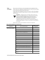
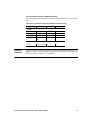
The following table gives the dimensions for the Traverse components.
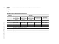
Table 1 Traverse Component Dimensions
Assembly
1
4
Height
Width
Weight
Empty
Depth
Weight
Fully
Loaded
Traverse
20001
18.33 in
21.1 in
13.75 in.
16 lbs
63 lbs
46.56 cm
53.6 cm
34.93 cm
7.2 kg
28.58 kg
Traverse
16001
18.33 in
17.25 in
13.75 in
15 lbs
52 lbs
46.56 cm
43.82 cm
34.93 cm
6.8 kg
23.59 kg
Traverse 600
6.50 in
17.25 in
13.75 in
8 lbs
21 lbs
16.51 cm
43.82 cm
34.93 cm
3.63 kg
9.525 kg
Traverse
2000
Fan Tray
(Front Inlet)
3.58 in
21.1 in
12.25 in
—
7 lbs
9.09 cm
53.6 cm
31.12 cm
—
3.180 kg
Traverse
1600
Fan Tray
(Front Inlet)
3.58 in
17.25 in
12.25 in
—
5 lbs
9.09 cm
43.82 cm
31.12 cm
—
2.27 kg
Traverse 600
Fan Tray
1.75 in
6.25 in
10.5 in
—
2.4 lbs
4.45 cm
15.88 cm
26.67 cm
—
1.09 kg
PDAP-4S
1.75 in
17.25 in
10 in
—
14 lbs
PDAP-15A
1.75 in
17.25 in
10 in
—
10 lbs
4.45 cm
43.82 cm
25.4 cm
—
4.5 kg
Height includes fan tray and depth includes cable covers.
Chapter 1
Traverse Equipment Specifications
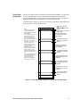
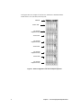
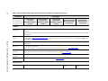
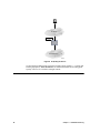
Traverse Rack
Configuration
The Traverse 1600 and Traverse 600 shelves install in either a standard 19-in (483 mm)
or 23-in (584 mm) wide relay rack. The Traverse 1600 and Traverse 600 shelves
requires mounting brackets for installing in a 23-in (584 mm) wide rack. The Traverse
2000 shelf installs only in a standard 23-in (584 mm) wide relay rack.
To provide proper air flow, 3/8-in (9.5 mm) of space is required between the PDAP and
the first (top most) Traverse shelf assembly.
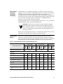
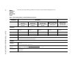
SD
Notes:
1. Pre-install shelf mounting
screws in locations shown to
take advantage of keyhole slots
to aid installation.
2. Leave about 1/4 in (.635 mm)
clearance between rack and
head of mounting screws .
3. This configuration requires
approximately 80.5 rack units of
usable space in the rack . [1
Rack Unit = 1.75 in (4.446 cm).]
4. The PDAP-4S must be
placed in the top of the rack .
The PDAP-4S uses the first set
of mounting holes for
installation. The top most 20slot shelf assembly goes directly
under the PDAP -4S. There
should be a slight gap between
the two units of about 3/8 in (1
cm).
5. The fan tray with integrated
air ramp mounts directly under
the 20-slot shelf assembly.
There should be no gap
between one shelf assembly
and the fan tray assembly .
82.00 in (208.5 cm) PDAP4S (top)
80.25 in (204.05 cm) PDAP-4S
bottom )
79.875 in (203.05 cm ) inches for
Shelf #1 (top)
18.75 in (46.36 cm) from top
of Shelf #1 to bottom of fan
tray for Shelf #1
Fan Tray with integrated air
ramp 61.125 in (156.69 cm)
(bottom )
18.75 in (46.36 cm) from top
of Shelf #2 to bottom of fan
tray for Shelf #2
Fan Tray with integrated air
ramp 42.375 in (110 .33 cm)
(bottom )
18.75 in (46.36 cm) from top of
Shelf #3 to bottom of fan tray
for Shelf #3
Fan Tray with integrated air
ramp 23.625 in (63.97 cm )
(bottom )
18.75 in (46.36 cm) from top of
Shelf #4 to bottom of fan tray
for Shelf #4
Fan Tray with integrated air
ramp 4.745 in (17.61 cm)
(bottom )
Figure 2 Traverse Mounting Heights in a 7-foot (2133.6 mm) Relay Rack
Planning and Engineering Guide, Release TR5.0.x/TN6.0.x
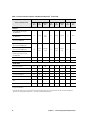
5
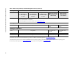
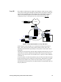
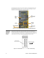
This figure shows an example of four Traverse 1600 shelves installed with the
PDAP-4S in a 19-in (483 mm) wide relay rack.
PDAP-4S
Traverse 1600
Fan Tray with
integrated air ramp
Traverse 1600
Fan Tray with
integrated air ramp
Traverse 1600
Fan Tray with
integrated air ramp
Traverse 1600
Fan Tray with
integrated air ramp
Figure 3 Rack Configuration with Four Complete Systems
6
Chapter 1
Traverse Equipment Specifications
Power
Consumption
The power draw of the Traverse system is dependent on the configuration of each
system. From a base configuration consisting of the chassis and a fan tray, the addition
of each card increases the power draw of the system.
A typical single shelf configuration consumes from 745 to 915 watts. Fully equipped
configurations are normally less than 1400 watts. All Traverse cards operate between
-40 and -60 VDC.
Important: Carefully plan your power supply capacity. The Force10
PDAP-4S with standard 40 Amp fuses at -40 VDC provides 1600 watts.
Force10 recommends using higher amperage fuses if your power
requirements go above a minimum of 1400 watts. If you fail to make
sufficient plans to meet the power requirements of your specific
configuration and the power draw goes above the maximum capacity of
your power supply design, it can cause a circuit breaker to trip resulting in a
loss of traffic.
The table below provides power information for all Traverse components.
Table 2 Power Distribution Per Traverse Card
Component
General Control Module
Watts Per Card /
Component
Card or Component Type
General Control Module (GCM) cards
35
GCM Enhanced (without optics and/or VTX/VCX)
40
GCM with 1- or 2-port OC-12 IR1/STM-4 SH1
42
GCM with 1- or 2-port OC-12 LR2/STM-4 LH2
42
GCM with 1-port OC-48 SR1/STM-16 SH1
55
GCM with 1-port OC-48 IR1/STM-16 SH1
55
GCM with 1-port OC-48 LR1/STM-16 LH1
55
GCM with 1-port OC-48 LR2/STM-16 LH2
55
GCM with VTX/VCX
46
GCM with 1- or 2-port OC-12 IR1/STM-4 SH1 plus VTX/VCX
48
GCM with 1- or 2-port OC-12 LR2/STM-4 LH2 plus VTX/VCX
48
GCM with 1-port OC-48 SR1/STM-16 SH1 plus VTX/VCX
61
GCM with 1-port OC-48 IR1/STM-16 SH1 plus VTX/VCX
61
GCM with 1-port OC-48 LR1/STM-16 LH1 plus VTX/VCX
61
GCM with 1-port OC-48 LR2/STM-16 LH2 plus VTX/VCX
61
GCM with 1-port OC-48 LR2/STM-16 LH2 CWDM
61
GCM with 1-port OC-48 LR2/STM-16 LH2 CWDM plus
VTX/VCX
61
GCM with 1-port OC-48 ELR/STM-16 LH DWDM, CH19,
191.9 GHz
61
Planning and Engineering Guide, Release TR5.0.x/TN6.0.x
7
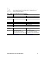
Table 2 Power Distribution Per Traverse Card (continued)
Component
SONET/SDH Cards
8
Watts Per Card /
Component
Card or Component Type
GCM with 1-port OC-48 ELR/STM-16 LH DWDM, CH19,
191.9 GHz plus VTX/VCX
61
Universal GCM with Extended Memory
21
4-port OC-3 IR1/STM-1 SH1
37
8-port OC-3 IR1/STM-1 SH1
38
8-port OC-3 LR2/STM-1 LH2
38
16-port OC-3/STM-1 IR1/SH1
60
16-port OC-3/STM-1 LR2/LH2
60
8-port STM SH1/OC-3 IR1
38
4-port OC-12 IR1/STM-4 SH1
42
4-port OC-12 LR2/STM-4 LH2
42
1-port OC-48 SR1/STM-16 SH1
41
1-port OC-48 IR1/STM-16 SH1
41
1-port OC-48 LR1/STM-16 LH1
41
1-port OC-48 LR2/STM-16 LH2
41
1-port OC-48 LR2/STM-16 LH2 ITU CWDM
41
1-port OC-48 LR2/STM-16 LH2 ITU CWDM
41
1-port OC-48/STM-16 DWDM ELR/LH, Ch [19–60]
41
1-port OC-48 VR2/STM-16 VLH
41
2-port OC-48 SR1/STM-16 SH1
52
2-port OC-48 IR1/STM-16 SH1
52
2-port OC-48 LR1/STM-16 LH1
52
2-port OC-48 LR2/STM-16 LH2
52
2-port OC-48 LR2/STM-16 LH2 ITU CWDM
52
8-port OC-48
100
1-port OC-192 SR1/STM-64 SH1
90
1-port OC-192 IR2/STM-64 SH2
90
1-port OC-192 LR2/STM-64 LH2
90
1-port OC-192 LR/STM-64 LH ITU DWDM
90
Chapter 1
Traverse Equipment Specifications
Table 2 Power Distribution Per Traverse Card (continued)
Component
Electrical Cards
Ethernet Cards
Watts Per Card /
Component
Card or Component Type
1-port OC-192 ELR/STM-64 LH ITU DWDM
90
28-port DS1
49
12-port DS3/E3/EC-1 Clear Channel
42
24-port DS3/E3/EC-1 Clear Channel
50
12-port DS3/EC-1 Transmux
46
21-port E1
49
UTMX-24
48
UTMX-48
55
VT/TU 5G Switch
42
VT-HD 40G Switch
112
4-port GbE (LX or SX) plus 16-port 10/100BaseTX
75
4-port GbE CWDM (40 km) plus 16-port 10/100BaseTX
2-port GbE TX plus 2-port GbE (LX or SX) plus 16-port
10/100BaseTX
2-port GbE LX CWDM plus 2-port GbE SX plus 16-port
10/100BaseTX
4-port GbE (LX or SX) plus 16-port 10/100BaseTX / CEP
85
2-port GbE TX plus 2-port GbE (LX or SX) plus 16-port
10/100BaseTX / CEP
4-port GbE LX plus 16-port 10/100BaseTX/EOPDH/CEP
85
4-port GbE SX plus 16-port 10/100BaseTX/EOPDH/CEP
2-port GbE TX plus 2-port GbE LX plus
16-port 10/100BaseTX/EOPDH/CEP
2-port GbE TX plus 2-port GbE SX plus
16-port 10/100BaseTX/EOPDH/CEP
Shelf Components
1-port 10GbE (LR, ER, ZR)
115 nominal (130 max)
10-port 1GbE (SX, LX, ZX, and TX)
125 nominal (140 max)
Front inlet fan tray Traverse 2000
30 nominal (60 max)
Front inlet fan tray Traverse 1600
30 nominal (55 max)
Fan tray Traverse 600
22 nominal (30 max)
PDAP-2S
<1
PDAP-4S
<1
Planning and Engineering Guide, Release TR5.0.x/TN6.0.x
9
Power Cabling
Redundant central office battery and battery return is connected to the PDAP. The
PDAP-2S distributes battery and battery return to up to two Traverse shelves and up to
ten pieces of auxiliary equipment in a rack. The PDAP-4S distributes battery and
battery return to up to four Traverse shelves and up to five pieces of auxiliary
equipment in a rack.
Both the PDAP-2S and PDAP-4S have two DC power inputs (Battery ‘A’ and
Battery ‘B’). Each of these inputs is capable of supplying power to the Traverse system
during central office maintenance operations. The recommended gauge wire for power
cabling is #8 AWG (a 9 mm2 cable).
See the Traverse Cabling Guide, Chapter 10—“Cable Management Specifications” for
detailed power cabling instructions.
Fiber
Connectors
and Cabling
MPX Connectors
Each optical card in a Traverse system can terminate up to 48 fibers, or support up to 24
optical interfaces. It has female duplex housings to accept the MPX multifiber array
connectors located on the optical cards. All MPX connectors have a precise alignment
mechanism to provide quick and easy installation. The optical backplane supports
single-mode and multi-mode fiber optic cable.
A fiber optic patch panel may be used to provide access and standard connectors (SC,
FC, ST, LC, or D4) for termination of fiber optic cables from the optical distribution
frame (ODF) and from the Traverse fiber optic backplane. Fiber optic cable with an
MPX female connector on one end must be used to make the connection at the Traverse
fiber optic backplane. An SC connector on the other end of the fiber optic cable is the
recommended option. Fiber optic cable with fan out for termination to single fiber
connectors (SC, FC, ST, LC, or D4) is another option.
For Ethernet Combo cards, Force10 provides an optional snap-in faceplate patch panel
for termination of fiber optic cables (4-port SC duplex adapter card for SM/MM) and
Category 5 cables (RJ-45 modular jack) for flexibility and better identification of pairs
terminated at the intermediate patch panel.
SFP Connector Module
The Traverse shelf also provides a small form-factor pluggable (SFP) connector
module (SCM) to support high-density and easy-operation fiber connection for the
10-port Gigabit Ethernet (GbE-10) module.
The GbE-10 module must be ordered with a 10-port SFP connector module (SCM).
Table 3 10-port GbE SFP Card Connector Module Type
Model Number
CONNECTOR-10P-SFP
10
Module Description
2-slot-wide, 10-Port SFP connector module (SCM) for 10-port
1GbE card (TRA-10P-1GE-SFP)
Chapter 1
Traverse Equipment Specifications
Electrical Coax
and Copper
Connectors
and Cabling
The DS3/E3/EC-1 Clear Channel and DS3/EC-1 Transmux cards are cabled using
standard coax cables with BNC or Mini-SMB connectors. Coax cables are connected to
the DS3/E3 electrical connector module (ECM) at the main backplane. The
10/100BaseTX, GbE TX plus 10/100BaseTX Combo, other GbE plus 10/100BaseTX
Combos, DS1, and E1 cards are cabled using standard twisted-pair copper cables with
Telco connectors. Twisted-pair cables are connected to 10/100BaseT, Ethernet
protection, or DS1/E1 ECMs at the main backplane.
The main backplane supports 1:N equipment protection, where N = 1 to 2, for electrical
TDM and Ethernet cards in cooperation with the ECM.
Important: The Traverse also supports 1:N DS3 Transmux equipment
protection groups for high-density optical transmux applications (using
STS1-TMX mode, where N = 3 to 12 for the 12-port DS3 Transmux cards
and N = 4 for the UTMX-24 and UTMX-48 cards. This application does
not require an ECM.
See the Traverse Cabling Guide, Chapter 2—“ECM Interface Specifications” for more
information on ECMs and electrical connector card specifications.
Shelf and Rack
Density
Each Traverse shelf provides high maximum switching capacities and interface
densities in a compact footprint to ensure optimal rack space utilization. The tables
below shows Traverse interface options, maximum switching capacities, and maximum
interface densities per shelf for interface cards and VT/VC cross-connect cards.
Table 4 Traverse Interface Options and Maximum Densities1
Traverse 2000
Service Interface Card
Cards
per
Shelf
Maximum switching capacity
Ports
per
Shelf
Traverse 1600
Ports per
Rack
Cards
per
Shelf
95 Gbps
Ports
per
Shelf
Traverse 600
Ports per
Rack
Cards
per
Shelf
75 Gbps
Ports
per
Shelf
15 Gbps
Electrical
28-port DS1
16
448
1792
12
336
1344
4
112
12-port DS3/E3/EC-1 Clear Channel
16
192
768
12
144
576
4
48
24-port DS3/E3/EC-1 Clear Channel
16
384
1536
12
288
1152
4
96
12-port DS3/EC-1 Transmux
(electrical w/ ECM or optical)
16
192
768
12
144
576
4
48
21-port E1
16
336
1344
12
252
1008
4
84
UTMX-24 (electrical w/ ECM or
optical)
16
384
1536
12
288
1152
4
96
UTMX-48 (electrical w/ ECM or
optical)
16
384
1536
12
288
1152
4
96
Planning and Engineering Guide, Release TR5.0.x/TN6.0.x
11
Table 4 Traverse Interface Options and Maximum Densities1 (continued)
Traverse 2000
Service Interface Card
Traverse 1600
Traverse 600
Cards
per
Shelf
Ports
per
Shelf
Ports per
Rack
Cards
per
Shelf
Ports
per
Shelf
Ports per
Rack
Cards
per
Shelf
Ports
per
Shelf
16
64/256
256/
1024
12
48/192
192/768
4
16/64
16
32/32/
256
128/128/
1024
12
24/24/
192
96/96/
768
4
8/8/64
1-port 10GbE (dual slot)
9
9
36
7
7
28
—
—
10-port GbE (dual slot)
8
80
320
6
60
240
—
—
4-port OC-3/STM-1
18
72
288
14
56
224
4
16
8-port OC-3/STM-1
18
144
576
14
112
448
4
32
4-port OC-12/STM-4
18
72
288
14
56
224
4
16
1-port OC-48/STM-16
18
18
72
14
14
56
4
4
2-port OC-48/STM-16
18
36
144
14
28
112
4
8
8-port OC-48 (SONET only, dual
slot)2
8
64
32
N/A
N/A
N/A
N/A
N/A
1-port OC-192/STM-64 (dual slot)
9
9
36
7
7
28
—
—
Ethernet
4-port GbE LX plus 16-port
10/100BaseTX
4-port GbE SX plus 16-port
10/100BaseTX
4-port GbE CWDM (40 km) plus
16-port 10/100BaseTX
2-port GbE TX plus 2-port GbE LX
plus 16-port 10/100BaseTX
2-port GbE TX plus 2-port GbE SX
plus 16-port 10/100BaseTX
2-port GbE SX plus 2-port GbE
CWDM (40 km) plus 16-port
10/100BaseTX
SONET/SDH
1
Unprotected densities.
2
8-port OC-48 cards are pre-provisioned in the DCS-768 matrix shelf. For more information, see the TransNav Management
System Provisioning Guide, Chapter 40—“Creating a Multi-Shelf Application.”
12
Chapter 1
Traverse Equipment Specifications
VT Card Interface Options and Maximum Density
The following table provides information on the maximum number of VT/VC cards per
shelf.
Table 4 VT Card Interface Options and Maximum Shelf Density
Traverse 2000
Traverse 1600
Traverse 600
2 cards per shelf
2 cards per shelf
2 cards per shelf
SDH ADM
5 cards per shelf
5 cards per shelf
2 cards per shelf
DCS 96
2cards per shelf
2 cards per shelf
n/a
DCS 384
10 cards per
shelf
n/a
n/a
2 cards per shelf
n/a
n/a
VT 5G
SONET ADM
VT 40G
DCS 768
Regulatory
Compliance
The Force10 Traverse systems are designed to comply with multiple standards such as
NEBS, UL and FCC. For information on compliance and certification standards for the
Traverse system, see Chapter 2—“Compliance.”
Planning and Engineering Guide, Release TR5.0.x/TN6.0.x
13
14
Chapter 1
Traverse Equipment Specifications
Chapter 2
Compliance
Introduction
The highest levels of quality testing and the most stringent compliance standards that
can be achieved are the goals of Force10 Networks. The Force10 Quality Management
System has met ISO 9000-2008 certification.
This chapter includes the following topics:
• Compliance and Certification
• ETSI Environmental Standards
• NEBS Compliance and Certification
• UL and FCC Standards
• Reliability at Force10 Networks
• Reliability Development
• Reliability in Production
Compliance
and
Certification
A CE Mark has been obtained for all products destined for the
European Telecommunications Standards Institute (ETSI) market. A
CE Mark on Force10’s products is based on the following testing:
• Electro-Magnetic Compatibility (EMC): ETS 300 386, EN55022,
EN55024, CISPR-22, Class A for deployment in other than telecommunication centers.
• Safety (CB Scheme): EN60950, CSA 22.2 No. 60950, AS/NZS
3260, IEC 60950-1 2nd Edition, compliant with all CB Scheme
member country deviations.
The next-generation Ethernet (NGE and NGE Plus), EoPDH, 10GbE
and GbE-10 cards are Metro Ethernet Forum Certified (MEF)
compliant with MEF EPL, EVPL and E-LAN service profiles to the
MEF 9 technical specification.
Planning and Engineering Guide, Release TR5.0.x/TN6.0.x
15
ETSI
Environmental
Standards
In addition to the testing required for a CE Mark, Force10’s products are also tested to
the following ETSI specifications:
• Storage: ETS 300 019-2-1, class T1.2
• Transportation: ETS 300 019-2-2, class T2.3
• Operational: ETS 300 019-2-3, class T3.1 and T3.1E
NEBS
Compliance
and
Certification
Network Equipment-Building Systems (NEBS) standards define a rigid and extensive
set of performance, quality, environmental, and safety requirements developed by
Telcordia.
Level Three Compliance
The NEBS testing for the Force10 Networks Traverse 2000, Traverse 1600, and
Traverse 600 systems includes all applicable tests specified in Telcordia document
SR-3580, commonly referred to as NEBS Level 3. The Force10 NEBS test program
includes, but is not limited to, the following tests:
• Acoustic noise
• Altitude to 13,000 feet above sea level
• Earthquakes: meets Zone 4 requirements
• Face plate temperature
• Heat dissipation
• Illumination
Acceptance criteria is in accordance with the most stringent standards imposed by
the Regional Bell Operating Companies (RBOCs). In some cases, these standards
exceed the criteria specified in GR-63-CORE and GR-1089-CORE.
WARNING! The intra-building port(s) of the equipment or
subassembly is suitable for connection to intra-building or unexposed
wiring or cabling only. The intra-building port(s) of the equipment or
subassembly MUST NOT be metallically connected to interfaces that
connect to the OSP or its wiring. These interfaces are designed for use
as intra-building interfaces only (Type 2 or Type 4 ports as described
in GR-1089-CORE, Issue 4) and require isolation from the exposed
OSP cabling. The addition of Primary Protectors is not sufficient
protection in order to connect these interfaces metallically to OSP
wiring.
UL and FCC
Standards
The Traverse 2000, Traverse 1600, and Traverse 600 systems are designed to comply
with UL 60950 and FCC part 15 requirements.
Reliability at
Force10
Networks
The Traverse 2000 and Traverse 1600 systems can be configured in the network in
several different ways:
• SONET/SDH terminal multiplexer
• SONET/SDH add/drop multiplexer
• Broadband/High Order digital cross connect
• Broadband/High Order switch
16
Chapter 2 Compliance
Most of the requirements specified by Telcordia for the above-listed types of
configurations are for a per-channel availability of 99.999%.
As required by GR-418-CORE and GR-499-CORE, circuit pack failure rate predictions
are performed in accordance with the requirements of TR-332. Also, GR-418-CORE
and SR-TSY-001171 are used in the analysis of system availability and other reliability
parameters. The current predicted per-channel availability meets the 99.999%
requirement.
Reliability Development
During product development, reliability growth is achieved primarily through Highly
Accelerated Life Testing (HALT). HALT is a proactive technique to improve products
and field reliability, not to measure the reliability of the product. The stresses applied
during HALT far exceed the field environment, and are intended to expose the weak
links in the design and processes in a very short period of time.
These stresses applied during HALT include such things as:
• Exposure to temperature extremes from as low as -50º C to as high as +110º C, or
to the upper destruct limit
• Rapid rates of change of temperature, as high as 60º C per minute
• Omni-axial random vibration, up to 30 G’s rms or to the upper destruct limit
• Power cycling
• Internal voltage margining
• Varying clock frequencies
• Exposure to high humidity
Once failures are precipitated during HALT, corrective action is implemented in order
to increase the robustness of the product. The HALT process continues in an effort to
identify the next weakest link. This HALT corrective action cycle continues until the
fundamental limit of the technology is reached, at which point the robustness of the
hardware has been optimized.
Where HALT is used to improve the reliability of the product, standard, accelerated-life
testing is used to measure the reliability of the improved product. Prior to releasing
hardware to production, accelerated life testing is conducted on an operating system, at
60° C for 1500 hours (minimum), far exceeding the GR-418-CORE requirement of
117 hours at 50° C. One purpose of this testing is to simulate the first year of
operational life and determine by way of life test data, the product mean time between
failure (MTBF) and availability.
Reliability in Production
The production process includes a comprehensive suite of tests designed to ensure
optimum product reliability and performance in the field. This production testing
includes the following:
• Automatic X-ray inspection
• In-circuit test, with boundary scan
• Board-level functional test
• System test
Planning and Engineering Guide, Release TR5.0.x/TN6.0.x
17
The automatic X-ray inspection is conducted on all circuit boards, with all components
and solder joints being inspected. For certain component technologies, such as
ball-grid-arrays (BGAs), there is no method other than X-ray that adequately verifies
solder quality.
18
Chapter 2 Compliance
Chapter 3
Network Feature Compatibility
Introduction
The Traverse system is a gateway solution providing unified feature support for both
SONET and SDH networks. As there are variances between these two network types,
Force10 offers the following topics:
• Compatibility Matrix for Network Features
• Comparative Terminology for SONET and SDH
Compatibility
Matrix for
Network
Features
Traverse gateway solutions (i.e., ITU_default and ANSI_default) provide features from
both SONET and SDH networks.
The following table provides you with a compatibility matrix for SONET and SDH
network feature set exceptions in Release TR5.0.x/TN6.0.x.
Table 1 Network Feature Compatibility Matrix
Feature
SONET Networks
SDH (ITU) Networks
Hardware
Not applicable
Software
1:N equipment protection for
VT/TU
N=1 to 9
n/a
Digital Cross-connect System
Multi-shelf DCS
(384 STS-1)
n/a
Optimized MSP
n/a
yes
Test Access
yes
n/a
Planning and Engineering Guide, Release TR5.0.x/TN6.0.x
19
Comparative
Terminology
for SONET and
SDH
The following table provides you with a short list of terms as they relate to the SONET
and SDH network feature sets.
Table 2 SONET and SDH Comparative Terminology
Term
20
SONET Network
SDH Network
1+1 ASP/MSP
1 plus 1 Automatic Protection Switch
(1+1 APS)
1 plus 1 Multiplex Section Protection
(1+1 MSP)
BLSR/MS-SPRing
Bidirectional Line Switched Ring
(BLSR)
Multiplex Section Shared Protection
Ring (MS-SPRing)
APS/MSP
Automatic Protection Switch (APS)
Multiplex Section Protection (MSP)
Broadband DCS
Broadband Digital Cross-connect
(B-DCS)
n/a
DS1/E1
Digital Signal Level 1 (DS1)
Note: T-carrier T1 equivalent.
European Level 1 (E1)
Note: E-carrier framing specification.
DS3/E3
Digital Signal Level 3 (DS3)
Note: T-carrier T3 equivalent.
European Level 3 (E3)
E-carrier framing specification.
EC-1
Electrical Carrier Level 1
Note: EC-1 is the STS-1 equivalent.
n/a
Line/Multiplex
Section
Line
Multiplex Section
OC-N/STM-N
Optical Carrier (OC) Level N (OC-N)
Synchronous Transfer Mode Level N
(STM-N)
OC-12/STM-4
OC Level 12 (OC-12)
STM Level 4 (STM-4)
OC-192/STM-64
OC Level 192 (OC-192)
STM Level 64 (STM-64)
Section/
Regenerator Section
Section
Regenerator Section
SONET/SDH
Synchronous Optical Network
(SONET)
Synchronous Digital Hierarchy (SDH)
STS/STM
Synchronous Transport Signal (STS)
Synchronous Transfer Mode (STM)
STS-1/TU-3
STS Level 1 (STS-1)
Tributary Unit (TU) Level 3 (TU-3)
STS-1/TUG-3
STS Level 1 (STS-1)
TU Group Level 3 (TUG-3)
VT-1.5/VC-11
VT Level 1.5 (VC-1.5)
Virtual Container (VC) Level 11
(VC-11)
VT-2/VC-12
VT Level 2
VC Level 12
STS/VC
Synchronous Transport Signal (STS)
Virtual Container (VC)
STS-1/AU-3
STS Level 1 (STS-1)
Administrative Unit Level 3 (AU-3)
STS-1/VC-3
STS Level 1 (STS-1)
VC Level 3 (VC-3)
Chapter 3 Network Feature Compatibility
Table 2 SONET and SDH Comparative Terminology (continued)
Term
SONET Network
SDH Network
STS-3c/AU-4
Contiguous concatenation of 3 STS-1
synchronous payload envelopes (SPE)
(STS-3c)
Administrative Unit Level 4 (AU-4)
STS-3c/VC-4
Contiguous concatenation of 3 STS-1
synchronous payload envelopes (SPE)
(STS-3c)
VC level 4 (VC-4)
STS-12c/VC-4-4c
Contiguous concatenation of 12 STS-1
SPEs (STS-12c)
Contiguous concatenation of 4 VCs at
Level 4 (VC-4-4c)
UPSR/SNCP
Unidirectional Path Switched Ring
Subnetwork Control Protocol (SNCP)
Ring
VT/LO
Virtual Tributary (VT)
Low Order (LO)
VT/VC
VT
Virtual Container (VC)
VT/TU
VT
Tributary Unit (TU)
VTX/VCX
VT Cross-connect (VTX)
VT Cross-connect (VCX)
Wideband DCS
Wideband Digital Cross-connect
System (WDCS)
n/a
Planning and Engineering Guide, Release TR5.0.x/TN6.0.x
21
22
Chapter 3 Network Feature Compatibility
Chapter 4
Protected Network Topologies
Introduction
This chapter includes the following topics:
• Point-to-Point or Linear Chain
• Ring
• Mesh
• Interconnected Ring Topologies
• Interconnected Gateway Topologies
• Supported Protected Topologies (Summary)
• Node and Tunnel Diversity for Low Order Tunneled Services
Point-to-Point
or Linear Chain
A simple point-to-point topology connects two nodes with two fibers. Traffic enters the
network at the source node (Node 1), passes through the intermediate nodes (Node 2),
to the destination node (Node 3). In a linear chain topology, the source and destination
nodes are connected through intermediate nodes; that is, they are connected only to one
other node in the network. Intermediate nodes are connected in both the upstream and
downstream directions.
Node 1
Node 2
Node 3
Figure 5 Simple Point-to-Point or Linear Chain Topology
The Traverse supports the following protection schemes for point-to-point topologies:
• 1+1 APS (automatic protection switching)
• 1+1 MSP (multiplex section protection)
• 1+1 MSP <–> 1+1 APS (gateway)
• 1+1 Optimized (SDH network only)
• 1+1 path protection over 1+1 APS, 1+1 MSP, or 1+1 Optimized. There can be any
combination of protection groups up to four links.
Planning and Engineering Guide, Release TR5.0.x/TN6.0.x
23
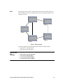
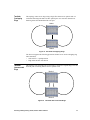
Ring
In a ring configuration, each node is connected to two adjacent nodes. Each node uses
two trunk cards (east and west). In a Traverse network, the port on the east card always
transmits the working signal clockwise around the ring. The port on the west card
always receives the working signal. In ring configurations, each east port is physically
connected to the west port of the next node.
Node 2
Node 1
Node 3
Node 4
Figure 6 Ring Topology
The Traverse supports the following protection schemes for ring topologies:
• UPSR (unidirectional path switched ring)
• 2 fiber BLSR (bidirectional line switched ring)
• SNCP (subnetwork control protocol) ring
• 2 fiber MS-SPRing (multiplex section shared protection ring)
24
Chapter 4 Protected Network Topologies
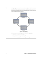
Mesh
This topology provides a direct connection from one node to every other node in the
network. Traffic is routed over a primary path as well as an alternative path in case of
congestion or failure.
.
Node 2
Node 5
Node 1
Node 4
Node 3
Figure 7 Mesh Topology
The Traverse supports the following protection schemes for mesh topologies:
• STS and VT 1+1 path protection
• High order and low order SNCP
Interconnected
Ring
Topologies
Force10 supports the following interconnected ring topologies:
• Single Node Interconnected Rings
• Two Node Overlapping Rings
• Two Node Interconnected Rings
• Four Node Interconnected Rings
Planning and Engineering Guide, Release TR5.0.x/TN6.0.x
25
Single Node
Interconnected
Rings
This topology uses one node to connect two separate rings. The interconnecting node
uses four optical ports (two for each ring). Each ring must use two ports on two
separate cards (east and west).
Node 1
Figure 8 Single Node Interconnection
The Traverse supports the following protection schemes in single node
interconnections:
• UPSR <–> UPSR
• UPSR <–> BLSR
• BLSR <–> BLSR
• UPSR <–> SNCP ring (gateway)
• SNCP ring <–> SNCP ring
• SNCP ring <–> MS-SPRing
• MS-SP ring <–> MS-SPRing
Interconnected
Gateway
Topologies
26
The Traverse supports the following interconnecting gateway topologies:
• 1+1 APS <–> 1+1 MSP
• UPSR <–> 1+ 1 MSP
• SNCP <–> 1+1 APS
• UPSR <–> SNCP
Chapter 4 Protected Network Topologies
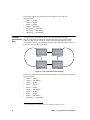
Two Node
Overlapping
Rings
This topology connects two rings using a single fiber between two optical cards. At
each interconnecting node there are three optical ports: two east and a shared west.
Each ring shares the bandwidth of the west port.
Node 1
Node 2
Figure 9 Two Node Overlapping Rings
The Traverse supports the following protection schemes in two node overlapping ring
interconnections:
• STS and VT 1+1 path protection
• High order and low order SNCP
Two Node
Interconnected
Rings
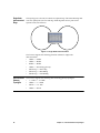
This topology uses four trunk ports in each node to connect two separate rings. The east
and west port of each ring must be on two separate cards.
Node 1
Node 2
Figure 10 Two Node Interconnected Rings
Planning and Engineering Guide, Release TR5.0.x/TN6.0.x
27
The Traverse supports the following protection schemes in two node ring
interconnections:
• UPSR <–> UPSR
• UPSR <–> BLSR
• BLSR <–> BLSR
• UPSR <–> SNCP ring
• SNCP ring <–> SNCP ring
• SNCP ring <–> MS-SPRing
• MS-SP ring <–> MS-SPRing
Four Node
Interconnected
Rings
This topology uses four nodes to connect two rings. The links between the
interconnecting nodes are unprotected or protected. This topology protects traffic
within each ring, as well as from any failure on the interconnecting node. In this
configuration, each ring can be different speeds, and the connecting links do not have to
be the same speed as either of the rings.
Node 1
Node 3
Node 2
Node 4
Figure 11 Four-node Interconnected Rings
The Traverse supports the following protection schemes in a four-node interconnected
ring configuration:
• UPSR <–> UPSR
• UPSR <–> MS-SPRing1
• UPSR <–> BLSR1
• SNCP <–> SNCP
• SNCP <–> UPSR
• SNCP <–> MS-SPRing1
• SNCP <–> BLSR1
• BLSR <–> BLSR1
• BLSR <–> MS-SPRing1
• MS-SPRing <–> MS-SPing1
1
28
Drop-and-continue not supported on interconnecting BLSR or MS-SP ring nodes.
Chapter 4 Protected Network Topologies
Supported
Protected
Topologies
(Summary)
This table summarizes supported topologies and protection schemes for a Traverse
network.
Table 3 Supported Protected Topologies
Protection Scheme
Topology
SONET
SDH
Gateway
Simple
point-to-point or
linear chain
1+1 APS
1+1 MSP
1+1 Optimized
1+1 MSP <–> 1+1 APS
1+1 MSP <–> UPSR
Ring
UPSR1
2F-BLSR
SNCP2 ring
2F MS-SPRing
SNCP <–> 1+1 APS
Mesh
1+1 Path
(STS and VT)
SNCP
n/a
Single node
interconnected rings
UPSR <–> UPSR
UPSR <–> BLSR
BLSR <–> BLSR
SNCP <–> SNCP
SNCP <–> MS-SPRing
MS-SPRing <–> MS-SPRing
SNCP <–> UPSR
Two node
overlapping rings
UPSR <–> UPSR
UPSR <–> BLSR
BLSR <–> BLSR
SNCP <–> SNCP
SNCP <–> MS-SPRing
MS-SPRing <–> MS-SPRing
n/a
Two node
interconnected rings
UPSR <–> UPSR
UPSR <–> BLSR
BLSR <–> BLSR
SNCP <–> SNCP
SNCP <–> MS-SPRing
MS-SPRing <–> MS-SPRing
UPSR <–> SNCP
Four node
interconnected rings
UPSR <–> UPSR
UPSR <–> BLSR3
BLSR <–> BLSR3
SNCP <–> SNCP
SNCP <–> MS-SPRing3
MS-SPRing <–> MS-SPRing3
UPSR <–> SNCP
UPSR <–> MS-SPRing3
BLSR3 <–> SNCP
BLSR <–> MS-SPRing3
1
Force10 supports both STS and VT path protection.
2
Force10 supports both high order and low order SNCP path protection.
3
Drop-and-continue not supported on interconnecting BLSR or MS-SPRing nodes.
Planning and Engineering Guide, Release TR5.0.x/TN6.0.x
29
Node and
Tunnel
Diversity for
Low Order
Tunneled
Services
Use of Low Order end-to-end tunneled services in your network requires additional
planning for node and tunnel diversity. For more information on Low Order end-to-end
SONET services, see the TransNav Management System Provisioning Guide,
Chapter 28—“Creating SONET Low Order End-to-End Services and Tunnels.”
In the following example, the two services shown have diverse tunnels but are not node
diverse since both tunnels are routed through the same node (Node CS 131).
CS 111
CS 112
14
13
13
14
Mesh
OC-48
12
13
13
14
CS 132
CS 131
14
11
14
Mesh
OC-48
13
3
Mesh
6
14
13
CS 133
11
DP 101
OC-192
11
DP 102
Figure 12 Low Order End-to-End Tunnel Diversity
30
Chapter 4 Protected Network Topologies
To ensure node diversity, define an egress point on the head node to assure tunneled
services use separate paths. In the following example, if an egress point of 11 is set on
Node CS 133, the tunneled service in red is routed through Node DP 102 to terminate
at Node CS 112.
CS 111
CS 112
14
13
13
14
Mesh
OC-48
12
13
13
14
CS 132
CS 131
14
11
14
Mesh
OC-48
13
3
Mesh
6
14
13
CS 133
11
DP 101
OC-192
11
DP 102
Figure 13 Low Order End-to-End Node Diversity
Planning and Engineering Guide, Release TR5.0.x/TN6.0.x
31
32
Chapter 4 Protected Network Topologies
Chapter 5
TransNav Management System Requirements
Introduction
The TransNav management system software package contains both server and client
workstation applications. The server functions communicate with the nodes and
maintain a database of topology, configuration, fault, and performance data for all
nodes in the network. The client workstation application provides the user interface for
managing the network.
The TransNav and TN-Xpert management system applications can co-exist in a
SONET-only environment and be run independently on a single workstation. System
requirements for a TransNav-only or TransNav/TN-Xpert combined system are defined
in this document.
For information on installing the TN-Xpert application on a SONET-only network, see
the TransNav Xpert Installation Guide.
Use the requirements listed in the following sections to help you determine the
management system requirements for your network.
• Management System Deployment
• TransNav Network Management
• Solaris Platform for TransNav Management Server
• Windows Platform Requirements for TransNav Management Server
• TransNav Management Server GUI Application Requirements
• TransNav Client and Node GUI Application Requirements
• TN-Xpert Client Application Guidelines
Planning and Engineering Guide, Release TR5.0.x/TN6.0.x
33
Management
System
Deployment
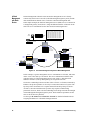
The TransNav management system software package contains server applications,
client workstation applications, and agent applications that reside on the node.
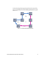
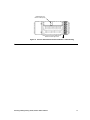
server response
client request
Client
Workstation
Management System
Server Host
Management
Gateway Server
Management
Gateway Server
Data Communications Network
Network Nodes
Network Nodes
TN 00031
Figure 6 Management System Deployment
Each TransNav management system supports up to eight servers; one server is
designated as the Primary server, the remaining optional servers are designated as
Secondary servers. The Primary server actively manages the network. The Secondary
servers passively view the network but cannot perform any management operations
that would change the state of the network. Any Secondary server can be promoted to
the Primary server role in case of failure or maintenance. The switch in server roles
requires some degree of user intervention.
The server applications communicate with the nodes and maintain a database of
topology, configuration, fault, and performance data for all nodes. The client
workstation application provides the user interface for managing the network (GUI or
CLI). The agent application resides on the node control card and maintains a persistent
database of management information for the node. It also controls the flow of
information between the management server and the node itself.
TransNav
Network
Management
In addition to the management system applications, the TransNav management system
uses the following Traverse software components:
Intelligent Control Plane
An Intelligent Control Plane is a logical set of connections between TransNav-managed
network elements through which those network elements exchange control and
management information. This control and management information can be carried
either in-band or out-of-band.
• See Chapter 7—“IP Address Planning,” Quality of Service for an example and
description of IP quality of service routing protocol.
• See Chapter 7—“IP Address Planning,” Proxy ARP for information on using the
proxy address resolution protocol.
34
Chapter 5
TransNav Management System Requirements
•
•
See Chapter 7—“IP Address Planning,” In-Band Management with Static
Routes for an example and a detailed description.
See Chapter 7—“IP Address Planning,” Out-of-Band Management with Static
Routes for an example and a detailed description.
Control Plane Domain
A control plane domain is a set of nodes completely interconnected by the intelligent
control plane. One TransNav management system can manage up to 200 nodes in a
single control plane domain. The number of nodes can be increased from 200 up to
1000 nodes with the addition of management gateway nodes to the network.
Domain management includes tasks such as:
• Setting the gateway node
• Configuring network links
• Creating performance monitoring templates and alarm profiles
• Creating protection rings and services
• Generating reports
Management Gateway Nodes
The TransNav management server connects to nodes over the service provider’s
TCP/IP data communications network. The management system accesses a network
through one or more nodes that are designated as management gateway nodes (MGN).
For in-band management, only one node is connected to the management server.
Therefore, there is one MGN in a network that is managed in-band.
For out-of-band management, each node is connected to the management server either
directly or through a router. Each node is considered a MGN.
Planning and Engineering Guide, Release TR5.0.x/TN6.0.x
35
36
Solaris
Platform for
TransNav
Management
Server
This table lists the minimum requirements for a Solaris system TransNav management server.
Table 4 Solaris Requirements, TransNav Management Server
Component
Description
Small networks
1-50 nodes
Less than or equal to
10 users
Medium networks
50-100 nodes
Less than or equal to
20 users
Large networks
100-200 nodes
Less than or equal to
30 users
Extra-large networks
More than 200 nodes
Over 40 users
Mega networks
500-1000 nodes
Over 40 users
Hardware
Chapter 5
TransNav Management System Requirements
System
SUN SPARC based
processor
SUN SPARC based
processor
SUN SPARC based
processor
SUN SPARC based
processor
SUN SPARC based
processor
Memory (RAM)
4 GB Memory
4 GB Memory
8 GB Memory
16 GB Memory
16 GB Memory
Hard Drives
80 GB of hard disk space
80 GB of hard disk space
160 GB of hard disk space
160 GB of hard disk space
160 GB of hard disk space
Backup System
Internal is optional; SAN (Storage Area Network) is recommended
Network
Two 10/100Base-T Ethernet cards. One card connects to the Data Communications Network (DCN) and the other card connects to the Local Area
Network (LAN) connecting the client workstations.
Software
Operating
Environment
Solaris 10
Management System
Software
Access the Force10 website at www.force10networks.com. A Customer Portal Account is required. From the website, select Services &
Support, then Account Request.
Optional Software
Radius Server1
Latest recommended Solaris patch clusters.
SSH Software2
Planning and Engineering Guide, Release TR5.0.x/TN6.0.x
Table 4 Solaris Requirements, TransNav Management Server (continued)
Component
Description
Small networks
1-50 nodes
Less than or equal to
10 users
PDF Viewer
Medium networks
50-100 nodes
Less than or equal to
20 users
Large networks
100-200 nodes
Less than or equal to
30 users
Extra-large networks
More than 200 nodes
Over 40 users
Mega networks
500-1000 nodes
Over 40 users
To view product documentation:
Adobe® Acrobat® Reader® 9.3 for Solaris.
Download the application for free from Adobe’s site at: www.adobe.com/.
Gateway Server
Not applicable
Recommend 2 Gateway
servers
Recommend 4 Gateway
servers
System
Not applicable
SUN SPARC based
processor
SUN SPARC based
processor
Memory (RAM)
Not applicable
8 GB Memory
8 GB Memory
Hard Drives
Not applicable
80 GB of hard disk space
80 GB of hard disk space
Gateway Server Hardware
1
2
The Radius server feature was tested with the following software: FreeRadius. Download the application at: www.freeradius.org/
The SSH software feature was tested with the OpenSSH application on the Solaris operating system and the PuTTY application on the Windows operating system.
Download the OpenSSH application at www.openssh.com/. Download the PuTTY application at: www.putty.org/
37
38
Solaris
Platform
Management
Server
Requirements
This table lists the minimum requirements for a Solaris system TransNav management server, including requirements allowing
TN-Xpert to reside on the same workstation server.
Table 5 Solaris Requirements, Management Server for TransNav and TN-Xpert
Component
Description
Small networks
1-50 nodes
Less than or equal to
10 users
Medium networks
50-100 nodes
Less than or equal to
20 users
Large networks
100-200 nodes
Less than or equal to
30 users
Extra-large networks
More than 200 nodes
Over 40 users
Mega networks
500-1000 nodes
Over 40 users
Hardware
Chapter 5
TransNav Management System Requirements
System
SUN SPARC based
processor
SUN SPARC based
processor
SUN SPARC based
processor
SUN SPARC based
processor
SUN SPARC based
processor
Memory (RAM)
4 GB Memory
8 GB Memory
16 GB Memory
16 GB Memory
16 GB Memory
Hard Drives
80 GB of hard disk space
80 GB of hard disk space
160 GB of hard disk space
160 GB of hard disk space
160 GB of hard disk space
Backup System
Internal is optional; SAN (Storage Area Network) is recommended
Network
Two 10/100Base-T Ethernet cards. One card connects to the Data Communications Network (DCN), and the other card connects to the Local Area
Network (LAN) connecting the client workstations.
Software
Operating
Environment
Solaris 10
Optional Software
Radius Server1
Latest recommended Solaris patch clusters.
SSH Software2
Management System
Software
Access the Force10 website at www.force10networks.com. A Customer Portal Account is required. From the website, select Services &
Support, then Account Request.
Planning and Engineering Guide, Release TR5.0.x/TN6.0.x
Table 5 Solaris Requirements, Management Server for TransNav and TN-Xpert (continued)
Component
Description
Small networks
1-50 nodes
Less than or equal to
10 users
PDF Viewer
Medium networks
50-100 nodes
Less than or equal to
20 users
Large networks
100-200 nodes
Less than or equal to
30 users
Extra-large networks
More than 200 nodes
Over 40 users
Mega networks
500-1000 nodes
Over 40 users
To view product documentation:
Adobe® Acrobat® Reader® 9.3 for Solaris.
Download the application for free from Adobe’s site at: www.adobe.com/.
Gateway Server
Not applicable
Not applicable
Not applicable
Not applicable
Recommend 2 Gateway
servers
Recommend 4 Gateway
servers
Gateway Server Hardware
1
2
System
Not applicable
Not applicable
Not applicable
SUN SPARC based
processor
SUN SPARC based
processor
Memory (RAM)
Not applicable
Not applicable
Not applicable
8 GB Memory
8 GB Memory
Hard Drives
Not applicable
Not applicable
Not applicable
80 GB of hard disk space
80 GB of hard disk space
The Radius server feature was tested with the following software: FreeRadius. Download the application at: www.freeradius.org/
The SSH software feature was tested with the OpenSSH application on the Solaris operating system and the PuTTY application on the Windows operating system.
Download the OpenSSH application at www.openssh.com/. Download the PuTTY application at: www.putty.org/
39
40
Windows
Platform
Requirements
for TransNav
Management
Server
This table lists the minimum requirements for a Windows platform TransNav management server.
Table 6 Windows Requirements, TransNav Management Server
Component
Description
Small networks
1-50 nodes
Less than or equal to
10 users
Medium networks
50-100 nodes
Less than or equal to
20 users
Large networks
100-200 nodes
Less than or equal to
30 users
System
Dual Core Pentium Class
Processor - 2.8 GHz
Dual Core Pentium Class
Processor - 3.0 GHz
Quad Core Xeon Class
Processor – 2.0 GHz
Quad Core Xeon Class
Processor – 2.8 GHz
Quad Core Xeon Class
Processor – 2.8 GHz
Memory (RAM)
4 GB Memory
4 GB Memory
8 GB Memory
8 GB Memory
8 GB Memory
Hard Drives
80 GB HD
80 GB HD
160 GB HD
160 GB HD
160 GB HD
Monitor
Server only: High resolution 15-inch (1024 x 768)
Server and client: High resolution 21-inch (1280 x 1024)
Disk Backup System
Required if unable to back up TransNav database to server on the network.
Network
One or two 10/100BaseT Ethernet cards. One Ethernet Network Interface Card (NIC) connects to the Data Communications Network (DCN). The
second optional Ethernet NIC connects to the Local Area Network (LAN) connecting the client workstations.
Extra-large networks
More than 200 nodes
Over 40 users
Mega networks
500 - 1000 nodes
Over 40 users
Hardware
Chapter 5
TransNav Management System Requirements
Planning and Engineering Guide, Release TR5.0.x/TN6.0.x
Table 6 Windows Requirements, TransNav Management Server (continued)
Component
Description
Small networks
1-50 nodes
Less than or equal to
10 users
Medium networks
50-100 nodes
Less than or equal to
20 users
Large networks
100-200 nodes
Less than or equal to
30 users
Extra-large networks
More than 200 nodes
Over 40 users
Mega networks
500 - 1000 nodes
Over 40 users
Software
Operating
Environment
Windows XP Professional Service Pack 3
Windows 7
Windows Server 2008
Management System
Software
Obtain the latest version of the TransNav management system software from the Customer Support webpage on the Force10 website. Access the
Force10 website at www.force10networks.com. A Customer Portal Account is required. From the website, select Services & Support, then
Account Request.
PDF Viewer
To view product documentation:
Adobe® Acrobat® Reader® 9.3 for Windows. Download the application for free from Adobe’s site at: www.adobe.com/
Optional Software
Radius Server1
SSH Software2
FTP server
application
To distribute TransNav software to network elements:
Telnet server
application
To access the TransNav management server remotely.
Compression
software
Force10 recommends the popular compression application WinZip. See www.winzip.com/.
Force10 recommends WAR FTP for Windows. Download the application for free from www.warftp.org.
41
42
Table 6 Windows Requirements, TransNav Management Server (continued)
Component
Description
Small networks
1-50 nodes
Less than or equal to
10 users
Medium networks
50-100 nodes
Less than or equal to
20 users
Large networks
100-200 nodes
Less than or equal to
30 users
Extra-large networks
More than 200 nodes
Over 40 users
Mega networks
500 - 1000 nodes
Over 40 users
Gateway Server
Not applicable
Not applicable
Not applicable
Not applicable
Recommend 2 Gateway
servers
Recommend 4 Gateway
servers
Gateway Server Hardware
Chapter 5
1
TransNav Management System Requirements
2
System
Not applicable
Not applicable
Not applicable
Quad Core Xeon Class
Processor – 2.8 GHz
Quad Core Xeon Class
Processor – 2.8 GHz
Memory (RAM)
Not applicable
Not applicable
Not applicable
8 GB Memory
8 GB Memory
Hard Drives
Not applicable
Not applicable
Not applicable
160 GB HD
160 GB HD
The Radius server feature was tested with the following software: FreeRadius. Download the application at:
www.freeradius.org/
The SSH software feature was tested with the OpenSSH application on the Solaris operating system and the PuTTY application on the Windows operating system.
Download the OpenSSH application at www.openssh.com/. Download the PuTTY application at: www.putty.org/
Planning and Engineering Guide, Release TR5.0.x/TN6.0.x
Windows
Platform
Management
Server
Requirements
This table lists the minimum requirements for a Windows platform TransNav management server, including requirements
allowing TN-Xpert to reside on the same server.
Table 7 Windows Requirements, Management Server with TransNav and TN-Xpert
Component
Description
Small networks
1-50 nodes
Less than or equal to
10 users
Medium networks
50-100 nodes
Less than or equal to
20 users
Large networks
100-200 nodes
Less than or equal to
30 users
Extra-large networks
More than 200 nodes
Over 40 users
Mega networks
500 - 1000 nodes
Over 40 users
Hardware
System
Quad Core Xeon Class
Processor – 2.0 GHz
Quad Core Xeon Class
Processor – 2.0 GHz
Quad Core Xeon Class
Processor – 2.8 GHz
Quad Core Xeon Class
Processor – 2.8 GHz
Quad Core Xeon Class
Processor – 2.8 GHz
Memory (RAM)
4 GB Memory
8 GB Memory
16 GB Memory
16 GB Memory
1+ GB Memory
Hard Drives
80 GB HD
80 GB HD
160 GB HD
200 GB HD
160 GB HD
Monitor
Server only: High resolution 15-inch (1024 x 768)
Server and client: High resolution 21-inch (1280 x 1024)
Disk Backup System
Required if unable to back up TransNav database to server on the network.
Network
One or two 10/100BaseT Ethernet cards. One Ethernet Network Interface Card (NIC) connects to the Data Communications Network (DCN). The
second optional Ethernet NIC connects to the Local Area Network (LAN) connecting the client workstations.
43
44
Table 7 Windows Requirements, Management Server with TransNav and TN-Xpert (continued)
Component
Description
Small networks
1-50 nodes
Less than or equal to
10 users
Medium networks
50-100 nodes
Less than or equal to
20 users
Large networks
100-200 nodes
Less than or equal to
30 users
Extra-large networks
More than 200 nodes
Over 40 users
Mega networks
500 - 1000 nodes
Over 40 users
Software
Operating
Environment
Windows XP Professional Service Pack 3
Windows 7
Windows Server 2008. Microsoft client licenses are not required for clients to connect to TransNav software running on Microsoft Windows 2008
Server platform.
Chapter 5
Management System
Software
Obtain the latest version of the TransNav management system software from the Customer Support webpage on the Force10 website. Access the
Force10 website at www.force10networks.com. A Customer Portal Account is required. From the website, select Services & Support, then
Account Request.
Optional Software
Radius Server1
SSH Software2
PDF Viewer
To view product documentation:
TransNav Management System Requirements
Adobe® Acrobat® Reader® 9.3 for Windows. Download the application for free from Adobe’s site at: www.adobe.com/
FTP server
application
To distribute TransNav software to network elements:
Telnet server
application
To access the TransNav management server remotely.
Compression
software
Force10 recommends the popular compression application WinZip. See www.winzip.com/.
Force10 recommends WAR FTP for Windows. Download the application for free from www.warftp.org.
Gateway Server
Not applicable
Recommend 2 Gateway
servers
Recommend 4 Gateway
servers
Planning and Engineering Guide, Release TR5.0.x/TN6.0.x
Table 7 Windows Requirements, Management Server with TransNav and TN-Xpert (continued)
Component
Description
Small networks
1-50 nodes
Less than or equal to
10 users
Medium networks
50-100 nodes
Less than or equal to
20 users
Large networks
100-200 nodes
Less than or equal to
30 users
Extra-large networks
More than 200 nodes
Over 40 users
Mega networks
500 - 1000 nodes
Over 40 users
Gateway Server Hardware
1
2
System
Not applicable
Not applicable
Not applicable
Quad Core Xeon Class
Processor – 2.8 GHz
Quad Core Xeon Class
Processor – 2.8 GHz
Memory (RAM)
Not applicable
Not applicable
Not applicable
8 GB Memory
8 GB Memory
Hard Drives
Not applicable
Not applicable
Not applicable
160 GB HD
160 GB HD
The Radius server feature was tested with the following software: FreeRadius. Download the application at: www.freeradius.org/
The SSH software feature was tested with the OpenSSH application on the Solaris operating system and the PuTTY application on the Windows operating system.
Download the OpenSSH application at www.openssh.com/. Download the PuTTY application at: www.putty.org/
45
TransNav
Management
Server GUI
Application
Requirements
You require a client workstation to access the TransNav management server from the
graphical user interface (GUI). Force10 recommends installing the application directly
on the client workstation for faster initialization, operation, and response time.
Table 8 TransNav Management Server GUI Application Requirements
Component
Description
Solaris Client Requirements
Windows Client Requirements
Hardware
CPU
Sun SPARC based processor
Windows PC with a Dual Core Pentium Class
Processor - 2.8 GHz
Memory (RAM)
4 GB
Hard Drive Space
80 GB or more recommended
Monitor
High resolution 21-inch (1280 x 1024) monitor or high resolution laptop
Network
One 10/100BaseT Ethernet Card
Software
Operating
Environment
Sun Solaris 10
Microsoft Windows XP Professional Service Pack 3
Microsoft Windows Vista
Microsoft Windows 7
PDF Viewer
Compression
software
46
To view product documentation:
To view product documentation:
Adobe® Acrobat® Reader® 9.3 for Solaris.
Adobe® Acrobat® Reader® 9.3 for Windows
Download the application for free from Adobe’s site
at: www.adobe.com/
Download the application for free from Adobe’s site
at: www.adobe.com/
Force10 recommends the popular compression application WinZip. See www.winzip.com/.
Chapter 5
TransNav Management System Requirements
TransNav
Client and
Node GUI
Application
Requirements
The TransNav Client and Node GUI are a subset of the TransNav server GUI. Access
to a TransNav management server is required only to download the application to the
client workstation or laptop. Information in the Node GUI is obtained directly from the
Traverse platform. The Node GUI release must match the corresponding Traverse
release to avoid unexpected behavior.
Table 9 TransNav Client and Node GUI Application Requirements
Component
Description
Solaris Client Requirements
Windows Client Requirements
Hardware
CPU
Sun SPARC based processor
Memory (RAM)
4 GB
Hard Drive Space
80 GB or more recommended
Monitor
High resolution 21-inch (1280 x 1024) monitor
Network
One 10/100BaseT Ethernet Card
Windows PC or laptop with a Dual Core Pentium
Class Processor - 2.8 GHz
High resolution 21-inch (1280 x 1024) monitor or
high resolution laptop
Software
Operating
Environment
Sun Solaris UltraSPARC
Microsoft Windows XP Professional Service Pack 3
PDF Viewer
To view product documentation:
Microsoft Windows 7
®
®
®
To view product documentation:
Adobe Acrobat Reader 9.3 for Solaris.
Adobe® Acrobat® Reader® 9.3 for Windows
Download the application for free from Adobe’s site
at: www.adobe.com/
Download the application for free from Adobe’s site
at: www.adobe.com/
Planning and Engineering Guide, Release TR5.0.x/TN6.0.x
47
TN-Xpert Client
Application
Guidelines
This table lists the minimum requirements for TN-Xpert Client workstations if the
TN-Xpert management system resides on the same server as the TransNav
management system.
Table 10 TN-Xpert Client GUI Application Requirements
Component
Description
Solaris Client Requirements
Windows Client Requirements
Hardware
CPU
Sun SPARC based processor
Windows PC or laptop with a Dual Core Pentium
Class Processor - 2.8 GHz
Memory (RAM)
4 GB
Hard Drive Space
80 GB or more recommended
Monitor
High resolution 21-inch (1280 x 1024) monitor
Network
One 10/100BaseT Ethernet Card
High resolution 21-inch (1280 x 1024) monitor or
high resolution laptop
Software
Operating
Environment
Solaris UltraSPARC
PDF Viewer
To view product documentation:
To view product documentation:
Adobe® Acrobat® Reader® 9.3 for Solaris.
Adobe® Acrobat® Reader® 9.3 for Windows
Download the application for free from Adobe’s site
at: www.adobe.com/
Download the application for free from Adobe’s site
at: www.adobe.com/
48
Microsoft Windows XP Professional Service Pack 3
Windows 7
Chapter 5
TransNav Management System Requirements
Chapter 6
TransNav Management System Planning
Introduction
This chapter outlines a recommended procedure to create and manage using the
TransNav management system.
SONET networks can be set up to also contain the TN-Xpert management system,
allowing you to access both the TransNav and TN-Xpert management systems,
Traverse nodes, TE-100 nodes, and TE-206 nodes from a single server. Currently, the
TE-206 nodes must be installed using the TN-Xpert management system and have an
IP address assigned. They can then be discovered on the TransNav management
system. For information on installing TN-Xpert, see the TransNav Xpert Installation
Guide.
Recommended
Procedure to
Create a
Network
Use these steps as a guideline to create a TransNav managed network.
Table 11 Network Configuration Procedure and References
Step
1
Procedure
Reference
Create a network plan.
Overview Guide
If you will be using SONET low
order end-to-end services in your
network, additional planning is
required. For more information, see
the TransNav Management System
Provisioning Guide,
Chapter 28—“Creating SONET
Low Order End-to-End Services
and Tunnels.”
TraverseEdge 100 User Guide
TraverseEdge 50 User Guide
TransAccess 200 Mux User Guide
SONET systems only:
• TransNav Xpert Installation Guide
• TransNav Xpert Users Guide
• TraverseEdge 206 Users Guide
2
Assign IP addresses to the
management server(s) and network
elements.
Chapter 7—“IP Address Planning”
3
Set a management server as the
primary NTP server.
Software Installation Guide, Chapter 1—“Creating the
Management Servers”
4
Add routes for the node-ips to the
management server.
This step depends on the server platform (Solaris or
Windows) and local site practices. Contact your local site
administrator.
5
Install the TransNav management
system software.
Software Installation Guide
Planning and Engineering Guide, Release TR5.0.x/TN6.0.x
49
Table 11 Network Configuration Procedure and References (continued)
Step
Procedure
Reference
6
Initialize, then start, the server. Start
the Primary server first, then
initialize and start the Secondary
servers.
Software Installation Guide
7
Install, connect, and commission
nodes and peripheral equipment
according to the network plan.
Traverse Hardware Installation and Commissioning
Guide
TraverseEdge 50 User Guide
TraverseEdge 100 User Guide
TransAccess 200 Mux User Guide
SONET systems only:
• TransNav Xpert Installation Guide
• TransNav Xpert Users Guide
• TraverseEdge 206 Users Guide
8
Start the user interface and discover
the nodes in the network.
Software Installation Guide
TransNav Management System Provisioning Guide
TraverseEdge 50 User Guide
TraverseEdge 100 User Guide
TransAccess 200 Mux User Guide
SONET systems only:
• TransNav Xpert Users Guide
• TraverseEdge 206 Users Guide
9
Configure timing options for the
network.
TransNav Management System Provisioning Guide
TraverseEdge 50 User Guide
TraverseEdge 100 User Guide
TransAccess 200 Mux User Guide
SONET systems only:
• TransNav Xpert Users Guide
• TraverseEdge 206 Users Guide
10
Create protection groups.
TransNav Management System Provisioning Guide
TraverseEdge 50 User Guide
TraverseEdge 100 User Guide
TransAccess 200 Mux User Guide
SONET systems only:
• TransNav Xpert Users Guide
• TraverseEdge 206 Users Guide
50
Chapter 6
TransNav Management System Planning
Table 11 Network Configuration Procedure and References (continued)
Step
Procedure
11
If necessary, configure equipment,
cards, and interfaces.
Reference
TransNav Management System Provisioning Guide
TraverseEdge 50 User Guide
TraverseEdge 100 User Guide
TransAccess 200 Mux User Guide
SONET systems only:
• TransNav Xpert Users Guide
• TraverseEdge 206 Users Guide
12
Create services or other
applications.
TransNav Management System Provisioning Guide
TraverseEdge 50 User Guide
TraverseEdge 100 User Guide
TransAccess 200 Mux User Guide
SONET systems only:
• TransNav Xpert Users Guide
• TraverseEdge 206 Users Guide
Planning and Engineering Guide, Release TR5.0.x/TN6.0.x
51
52
Chapter 6
TransNav Management System Planning
Chapter 7
IP Address Planning
Introduction
This chapter includes the following information on creating and managing a network
using the TransNav management system:
• IP Addresses in a TransNav Network
• IP Addressing Guidelines
• Quality of Service
• Proxy ARP
• In-Band Management with Static Routes
• In-Band Management with Router and Static Routes
• In-Band Management of CPEs Over EOP Links
• Out-of-Band Management with Static Routes
• For information on provisioning IP QoS, see the TransNav Management System
Provisioning Guide, Chapter 5—“Configuring IP Quality of Service.”
IP Addresses
in a TransNav
Network
The network management model (in-band or out-of-band) determines the IP address
requirements of the network. A TransNav-managed network requires a minimum of
two separate IP network addresses as indicated below.
Note: If you have a SONET-only system that includes TE-206 nodes, you must first
commission the TransNav management system, then commission the TE-206 nodes
using TN-Sight. You can then connect to the TE-206 nodes from the TransNav GUI
using an IP address. For more information on managing TE-206 nodes from the
TransNav GUI, see the TransNav Management System GUI Guide, Chapter 6—“Using
TransNav GUI with TN-Sight.”
• The IP address assigned to the Ethernet interface on the back of the shelf
(bp-dcn-ip) determines the physical network.
• The IP address assigned to the node (node-ip) is used by the management server
to manage the network.
If your network includes gateway applications for additional scalability, you must also
have an IP address for each machine that has a gateway application installed.
Planning and Engineering Guide, Release TR5.0.x/TN6.0.x
53
Assign the relevant IP addresses through the CLI during node commissioning.
Table 12 IP Address Node Connectivity Parameters
Parameter
Name
Required?
Force10
Recommendation
Description
node-id
Required on
every node
A user-defined name of the node. Enter
alphanumeric characters only. Do not use
punctuation, spaces, or special characters.
Use the site name
or location.
node-ip
Required on
every node
This parameter specifies the IP address of the node.
This address is also known as the Router ID in a
data network environment.
10.100.100.x
where x is
between 1 and
254.
In a non-proxy network, Force10 recommends that
this address be the same as the bp-dcn-ip. If it is
not equal to the bp-dcn-ip, it must be on a different
IP network.
Use a unique
number for each
network node.
Force10 recommends that the node-ips for all
nodes in one network be on the same IP network.
In a proxy network, the node-ips for all nodes
in one network must be on the same IP network.
This IP address has the following characteristics:
Depends on
network plan and
site practices.
For the proxy node, proxy-arp is enabled; the
bp-dcn-ip and the node-ip must be the same
IP address.
For the other nodes in the proxy network, the
node-ip must be in the same subnetwork as the
bp-dcn-ip address of the proxy node.
bp-dcn-ip
bp-dcn-ma
sk
54
Required on
each node
that is
connected
or routed to
the
managemen
t server or
on any node
with a
subtended
device.
Required
for each
bp-dcn-i
p
This parameter specifies the IP address assigned to
the Ethernet interface on the back of the node.
In a non-proxy network, Force10 recommends that
this address be the same as the node-ip. If it is
not equal to the node-ip, it must be on a different
IP network.
Use a different
subnet for each
site.
Enter an IP address if this node is connected to the
management server (either directly or through a
router) or to a TransAccess product.
In a proxy network on a proxy node, the
bp-dcn-ip and the node-ip must be the same
IP address.
Depends on
network plan and
site practices.
Enter the appropriate address mask of the
bp-dcn-ip address.
Depends on site
practices.
Chapter 7 IP Address Planning
Table 12 IP Address Node Connectivity Parameters (continued)
Parameter
Name
bp-dcn-gw
-ip
ems-ip
Required?
Description
Required
for each
bp-dcn-i
p
If the node is connected directly to the management
server, this address is the IP gateway of the
management server.
Required if
there is a
router
between this
node and
the
managemen
t server.
This address is the IP address of the TransNav
management server.
Force10
Recommendation
Depends on site
practices.
If there is a router between the management server
and this node, this address is the IP address of the
port on the router connected to the Ethernet
interface on the back of the Traverse node.
Depends on site
practices.
This IP address must be on a separate network from
any node-ip and gcm-{a | b}-ip.
For in-band management, this address must be on
or routed to the same network as the bp-dcn-ip of
the management gateway node (the node with the
physical connection to the management server).
For out-of-band management, this address must be
connected or routed to all bp-dcn-ip addresses.
ems-gw-ip
Required
for each
ems-ip.
This address is the IP address of the port on the
router connected to the Ethernet interface on the
back of the Traverse shelf. This address is the same
address as bp-dcn-gw-ip.
Depends on site
practices.
ems-mask
Required
for each
ems-ip.
Required if there is a router between the node and
the management server. This address is the address
mask of the IP address on the management server
(ems-ip).
Depends on site
practices.
proxy-arp
Required on
the node
acting as
proxy server
for the IP
subnet.
Enable this parameter if this node is to be used as
the proxy server for the IP subnet.
Depends on
network plan and
site practices.
IP Addressing
Guidelines
The bp-dcn-ip and the node-ip of the proxy node
must be the same IP address.
Once you plan the network with one node as the
proxy, you cannot arbitrarily re-assign another node
to be the proxy ARP server.
IP Networks and Proxy ARP
On the proxy node:
• The Proxy ARP parameter must be enabled on the management gateway node. In
Map View, click a node, click the Config tab, and change the value in Proxy ARP
to enabled.
Planning and Engineering Guide, Release TR5.0.x/TN6.0.x
55
•
The bp-dcn-ip and the node-ip of the proxy node must be the same IP address.
In a proxy network, all of the node-ip addresses must be in the same subnetwork as the
bp-dcn-ip of the proxy node.
Once you plan the network with one node as the proxy, you cannot arbitrarily re-assign
another node to be the proxy ARP server.
In-Band Management with Static Routes
General guidelines to assign IP addresses in a TransNav network managed in-band with
static routes are:
• Force10 recommends that all node-ip addresses are in a physically non-existent
(virtual) IP network.
• For the node connected to the management server (either directly or through a
router), all IP addresses provisioned on the node MUST be in separate networks.
• For all other nodes in the network, the node-id and the node-ip are the only
required commissioning parameters.
• The management server must be able to communicate with all node-ip addresses.
– Add routes to the management server using the node-ip, the address mask of
the bp-dcn-ip, and bp-dcn-ip of the node that is connected to the management
server.
– The IP address of the management server must be on or routed to the same
network as the bp-dcn-ip of the management gateway node.
Out-of-Band Management with Static Routes
General guidelines to assign IP addresses in a TransNav network managed out-of-band
with static routes are:
• Force10 recommends that all node-ip addresses are in a physically non-existent
(virtual) IP network.
• Each node is connected to the management server through an IP network. All IP
addresses provisioned on one node are in separate networks.
• The management server must be able to communicate with all node-ip addresses.
– Add routes using the node-ip, address mask of the bp-dcn-ip, and the IP
address of the port on the router that is connected to the management server.
– The IP address of the management server must be connected or routed to all
bp-dcn-ip addresses.
Out-of-Band Management with no DCC Connectivity
If there is no DCC connectivity between individual nodes, each node must still
communicate to the node-ip of the other nodes in the network. In this case, create
routes at relevant IP routers for all node-ips in the network.
TraverseEdge 50 and TransAccess Mux
The node to which the TraverseEdge 50 or TransAccess Mux is connected must have
the backplane IP address information provisioned:
• bp-dcn-ip: For in-band management, this address must be in a separate network
than the bp-dcn-ip of the node that is connected to the management server.
56
Chapter 7 IP Address Planning
•
•
bp-dcn-gw-ip: This address is in the same subnetwork as the bp-dcn-ip of this
node.
bp-dcn-mask: The address mask of the bp-dcn-ip of this node.
The IP address of the TransAccess Mux will have the following characteristics:
• IP address: This IP address can be on the same subnetwork as the node bp-dcn-ip.
• Gateway: This IP address is the bp-dcn-ip of the node.
• Mask: This mask is the address mask of the bp-dcn-ip of the node.
• Trap-1: This address is the bp-dcn-ip of the node to which it is connected.
Quality of
Service
The IP QoS (IP Quality of Service) routing protocol enables a Traverse node to
broadcast its forwarding table over the backplane for the data control network
(bp-dcn-ip), thus improving the quality of service over the backplane DCN ethernet
interface. Setting up static routes on intermediate routers between the Traverse
management gateway element and the TransNav management server is no longer
necessary. Existing traffic engineering and security capabilities are not changed.
When IP QoS is enabled on the management gateway node during commissioning,
source IP address packets are user-configured to block or allow traffic originated by
certain IP hosts or networks using the access control list (ACL). Received packets are
filtered, classified, metered, and put in queue for forwarding.
The ACL searches received IP address packets for the longest prefix match of the
source IP address. When the address is found, it is dropped or forwarded according to
the ACL settings (permit or deny). If no instruction is present in the ACL, the packet is
forwarded.
Outgoing IP address packets are prioritized as either High Priority or Best Effort and
put in queues for forwarding. The queue size for outgoing address packets is set by the
percent of available bandwidth.
Planning and Engineering Guide, Release TR5.0.x/TN6.0.x
57
EMS Server
IP Network
IP QoS
Enabled
Port IP A
Traverse Network
TN 00155
Figure 8 IP Quality of Service
See the TransNav Management System Provisioning Guide, Chapter 9—“Creating and
Deleting Equipment,” Node Parameters for detailed information about setting up IP
Quality of Service in a TransNav-managed network.
58
Chapter 7 IP Address Planning
Proxy ARP
Proxy address resolution protocol (ARP) is the technique in which one host, usually a
router, answers ARP requests intended for another machine. By faking its identity, the
router accepts responsibility for routing packets to the real destination. Using proxy
ARP in a network helps machines on one subnet reach remote subnets without
configuring routing or a default gateway. Proxy ARP is defined in RFC 1027.
IP
Gateway
Mask
172.168.0.2
172.168.0.1
255.255.255.0
IP Network
EMS Server
172.140.0.1
Port IP A
node-id
node-ip
Node1
172.140.0.2
172.140.0.2
172.140.0.1
255.255.255.0
172.168.0.2
172.140.0.1
255.255.255.0
enabled
disabled
0
TE-100
NodeA
172.140.0.5
Node3
172.140.0.4
TE-100
node-id
node-ip
NodeB
172.140.0.6
TE-100
NodeC
172.140.0.7
node-id
node-ip
node-id
node-ip
bp-dcn-ip
bp-dcn-gw-ip
bp-dcn-mask
ems-ip
ems-gw-ip
ems-mask
Proxy ARP
ospf-over-dcn
area-id
172.182.1.0
Node2
172.140.0.3
172.182.1.1
172.182.1.0
255.255.255.0
Gateway
node-id
node-ip
bp-dcn-ip
bp-dcn-gw-ip
bp-dcn-mask
Optional
TransAccess
Mux
TransAccess
172.182.1.2
172.168.1.1
255.255.255.0
172.182.1.1
node-id
node-ip
Name
IP
Gateway
Mask
Trap-1
TN 00156
Figure 9 Traverse Node Enabled as a Proxy ARP Server
In this example network, the EMS server communicates through an IP network to
Node 1. Node 1 (the proxy node) learns all the IP addresses of the nodes in the
subtending network and takes responsibility to route packets to and from the correct
destinations.
The EMS server keeps the IP-to-network-address mapping found in the reply in a local
cache and uses it for later communication with the nodes. The proxy node can proxy
addresses for any Traverse node, TraverseEdge node, or TransAccess Mux equipment
connected to it.
In a proxy network, all of the node-ip addresses must be in the same subnetwork as the
bp-dcn-ip of the proxy node. On the proxy node, the Proxy ARP parameter is enabled
and the bp-dcn-ip and the node-ip must be the same IP address. Once you plan the
network with one node as the proxy, you cannot arbitrarily re-assign another node to be
the proxy ARP server.
Planning and Engineering Guide, Release TR5.0.x/TN6.0.x
59
In-Band
Management
with Static
Routes
In-band management with static routes means the management server is directly
connected by static route to one node (called the management gateway node), and the
data communications channel (DCC) carries the control and management data.
In this simple example, the TransNav management server (EMS server) is connected to
a management gateway node (Node 1) using the Ethernet interface on the back of the
shelf. The server communicates to the other nodes in-band using the DCC.
172.168.0.10
172.168.0.1
255.255.255.0
EMS
Server
172.168.0.1
IP
Gateway
Mask
Add routes to EMS server for each node-ip.
<node-ip> <mask> <bp-dcn-ip of Node1>
10.100.100.1 255.255.255.0 172.168.0.2
10.100.100.2 255.255.255.0 172.168.0.2
10.100.100.3 255.255.255.0 172.168.0.2
10.100.100.4 255.255.255.0 172.168.0.2
10.100.100.5 255.255.255.0 172.168.0.2
10.100.100.6 255.255.255.0 172.168.0.2
Port A IP
Node1
10.100.100.1
172.168.0.2
172.168.0.1
255.255.255.0
Node6
10.100.100.6
Node3
10.100.100.3
TE-100
node-id
node-ip
Node5
10.100.100.5
node-id
node-ip
TransAccess
Mux
TE-100
Node4
10.100.100.4
172.168.1.1
Node2
10.100.100.2
172.168.1.2
172.168.1.1
255.255.255.0
TE-100
node-id
node-ip
node-id
node-ip
bp-dcn-ip
bp-dcn-gw-ip
bp-dcn-mask
node-id
node-ip
Port B IP
node-id
node-ip
bp-dcn-ip
bp-dcn-gw-ip
bp-dcn-mask
Optional
TransAccess
172.168.1.3
172.168.1.2
255.255.255.0
172.168.1.2
Name
IP
Gateway
Mask
Trap-1
TN 00157
Figure 10 TransNav Management System In-Band Management
In this example, to get the management server to communicate to all nodes, add routes
on the server to the node-ip of each node. The server communicates with the nodes
using the bp-dcn-ip of the management gateway node (Node 1). Note that all IP
addresses on Node 1 (node-ip and bp-dcn-ip) are in separate networks.
Node 2 has a subtending TransAccess Mux (either a TA155 or a TA200) connected by
Ethernet. The bp-dcn-ip address is necessary to connect the TransAccess system. The
bp-dcn-ip of this node must be in a separate network from the bp-dcn-ip on Node 1.
At Node 3, the node-id and the node-ip are the only required commissioning
parameters. However, Node 3 also has subtending TraverseEdge 100 network managed
in-band through the management gateway node. The IP address requirements are the
same as for the Traverse platform.
See the topic IP Addresses in a TransNav Network for detailed information about
assigning IP addresses in a TransNav-managed network.
60
Chapter 7 IP Address Planning
In-Band
Management
with Router
and Static
Routes
In this example, the management server is connected by static route to a router that, in
turn, is connected to the management gateway node (Node 1). The server
communicates to the other nodes in-band using the DCC.
EMS
Server
172.169.0.10
172.169.0.1
255.255.255.0
Add routes for each node-ip to EMS server.
<node-ip> <mask> <Router Port IP A>
10.100.100.1 255.255.255.0 172.169.0.1
10.100.100.2 255.255.255.0 172.169.0.1
10.100.100.3 255.255.255.0 172.169.0.1
10.100.100.4 255.255.255.0 172.169.0.1
10.100.100.5 255.255.255.0 172.169.0.1
10.100.100.6 255.255.255.0 172.169.0.1
IP
Gateway
Mask
172.169.0.1
Port IP A
172.168.0.1
Port IP B
Add routes for each node-ip to router.
<node-ip> <mask> <Node1 bp-dcn-ip>
10.100.100.1 255.255.255.0 172.168.0.2
10.100.100.2 255.255.255.0 172.168.0.2
10.100.100.3 255.255.255.0 172.168.0.2
10.100.100.4 255.255.255.0 172.168.0.2
10.100.100.5 255.255.255.0 172.168.0.2
10.100.100.6 255.255.255.0 172.168.0.2
Node1
10.100.100.1
172.168.0.2
172.168.0.1
255.255.255.0
172.169.0.10
172.168.0.1
255.255.255.0
node-id
node-ip
TE-100
Node6
10.100.100.6
Node3
10.100.100.3
node-id
node-ip
node-id
node-ip
bp-dcn-ip
bp-dcn-gw-ip
bp-dcn-mask
ems-ip
ems-gw-ip
ems-mask
Node2
10.100.100.2
172.168.1.2
172.168.1.1
255.255.255.0
Node5
10.100.100.5
TE-100
Node4
10.100.100.4
TransAccess
Mux
node-id
node-ip
node-id
node-ip
bp-dcn-ip
bp-dcn-gw-ip
bp-dcn-mask
Optional
TE-100
node-id
node-ip
Gateway
172.168.1.1
TransAccess
172.168.1.3
172.168.1.2
255.255.255.0
172.168.1.2
Name
IP
Gateway
Mask
Trap-1
TN 00158
Figure 11 In-Band Management with Router and Static Routes
In this example, to get the management server to communicate to each node, add routes
on the server to the node-ip of each node. The gateway through which the management
server communicates with the nodes is the IP address of the port on the router
connected to the server.
At the router, add the routes for each node-ip using the gateway bp-dcn-ip of the
management gateway node (Node 1).
See the topic IP Addresses in a TransNav Network for detailed information about
assigning IP addresses in a TransNav-managed network.
Planning and Engineering Guide, Release TR5.0.x/TN6.0.x
61
In-Band
Management of
CPEs Over
EOP Links
In this example, the management server is connected by static route to a router that, in
turn, is connected to the management gateway node (Node 1). The server
communicates to the other nodes in-band using the DCC, including the node that has
CPE devices attached (Node 3). The IP packets from CPE devices are forwarded
through the node over electrical cards to EOP links on the EoPDH cards, and then
through the Ethernet Control Channel interface (ECCI) for forwarding over the system
by Traverse Ethernet services.
Add routes for Traverse network to EMS server
<node-ip> <mask> <Router Port IP A>
10.100.100.0 255 .255 .255.0 172 .169.0.1
EMS
Server
172.169 .1.10
Add routes for CPE -ip's to EMS server
<CPE-ip> <mask >
< Router Port IP A>
192.168.0.0 255 .255 .0.0 172 .169 .1.10
IP
172.169 .0.1
Port IP A
10.100.100 .1
Port IP B
Node1
10.100.100 .5
10.100.100 .1
10.100.100 .1
255 .255. 255.0
172.169 .0. 0
10.100.100 .1
255.255 .0. 0
CPEs
CPE-ip
192.168 .20.2
CPE-ip 192 .168.20.3
CPE-ip
192.168 .20.4
CPE-ip
192.168 .20.5
Add routes to reach each CPE -ip to router
<CPE-ip>
< mask> < Router Port IP A>
192.168.0.0 255 .255 .0.0 10 .100.100.5
node -id
node -ip
bp-dcn-ip
bp-dcn-gw-ip
bp-dcn-mask
ems-ip
ems-gw-ip
ems-mask
EoPDH, Slot 5
CPE-ip 192 .168.20.6
Node2
10.100.100 .2
ECC
node -id
node -ip
CPEs
Node3
10.100. 100.3
CPE-ip 192. 168.30.2
CPE-ip
192.168. 30.3
CPE-ip 192. 168.30.4
CPE-ip 192. 168.30.5
CPE-ip
192.168. 30.6
EoPDH, Slot 8
node-id
node-ip
Entered on GCM . Routes packets to Slot 5
192.168 .20.1
ecci-gw-ip
255 .255.255.0
ecci-gw-mask
Entered on GCM. Routes packets to Slot 8
ecci-gw-ip
192.168 .30.1
ecci-gw-mask
255 .255.255.0
TN 00160
Figure 12 In-Band Management of CPEs Over EOP Links
In the above example, add routes on the management server to communicate to the
node-ip of the nodes that have CPEs attached. This allows IP packets from the CPEs to
be transmitted over the Traverse system. The server communicates with all the nodes
over a static route using the bp-dcn-ip of the management gateway node (Node 1).
At Node 3, the node-id and node-ip are required commissioning parameters, as are the
CPE-ip’s of each CPE device. A default ECC interface gateway IP address (ecci-gw-ip)
must also be configured on each CPE device to allow all IP packets to be sent through
the electrical card to the ECC interface on the node. Node 3 must have an EoPDH card
with an EOP port set up. Each EOP port is a member port on the ECC interface. The
VLAN tag of each ECCI member port corresponds to the management VLAN of the
attached CPE device, thus providing the interface between the CPEs and the
management system using an ECC interface.
62
Chapter 7 IP Address Planning
The EoPDH cards are connected by EOP links through the electrical cards to the CPEs
as shown below.
Figure 13 Connecting CPEs through EOP Links
See the topic IP Addresses in a TransNav Network for detailed information about
assigning IP addresses in a TransNav-managed network.
Planning and Engineering Guide, Release TR5.0.x/TN6.0.x
63
Out-of-Band
Management
with Static
Routes
Out-of-band management with static routes means that the management server is
directly connected by static route to each node by the Ethernet interface on the back of
each shelf. In this example, the management server communicates to each node directly
or through a router.
Add routes for each node-ip to router.
<node-ip> <mask> <Router Port IPs F & D>
10.100.100.2 255.255.255.0 172.169.0.2
10.100.100.3 255.255.255.0 172.170.0.2
IP Network
IP Network
172.168.0.1
Port IP A
IP
Gateway
Mask
172.168.0.2
172.168.0.1
255.255.255.0
EMS
Server
Add routes for each node-ip to EMS server.
10.100.100.1 255.255.255.0 172.168.0.3
10.100.100.2 255.255.255.0 172.168.0.1
10.100.100.3 255.255.255.0 172.168.0.1
Add route for node-ip to router.
<node-ip> <mask> <Node2 bp-dcn-ip>
10.100.100.2 255.255.255.0 172.171.0.2
Add route for node-ip to router.
<node-ip> <mask> <Node3 bp-dcn-ip>
10.100.100.3 255.255.255.0 172.182.0.2
Port IP D
172.170.0.2
Port IP F
172.169.0.2
node-id
Node1
10.100.100.1 node-ip
bp-dcn-ip
172.168.0.3
bp-dcn-gw-ip
172.168.0.1
255.255.255.0 bp-dcn-mask
172.168.0.2
ems-ip
172.168.0.1
ems-gw-ip
255.255.255.0 ems-mask
172.182.0.1
Port IP E
Node3
node-id
node-ip 10.100.100.3
bp-dcn-ip 172.182.0.2
bp-dcn-gw-ip 172.182.0.1
bp-dcn-mask 255.255.255.0
ems-ip 172.168.0.2
ems-gw-ip 172.182.0.1
ems-mask 255.255.255.0
172.171.0.1
Port IP G
Node2
node-id
10.100.100.2 node-ip
172.171.0.2
bp-dcn-ip
172.171.0.1
bp-dcn-gw-ip
255.255.255.0 bp-dcn-mask
172.168.0.02 ems-ip
172.171.0.1
ems-gw-ip
255.255.255.0 ems-mask
TransAccess
Mux
TransAccess Name
172.171.0.3 IP
172.171.0.2 Gateway
255.255.255.0 Mask
10.100.100.2 Trap-1
TN 00159
Figure 14 TransNav Management System Out-of-Band Management
Add a route to the management server using the bp-dcn-ip of Node 1. Add separate
routes to the node-ip of Node 2 and Node 3 using the IP address of the port on the
router connected to the server (Port IP A) as the gateway address.
At each router in the network, an administrator must add a route to the node-ip of the
nodes.
At Node 2, the bp-dcn-ip can be in the same network as the TransAccess Mux
connected to it.
See the topic IP Addresses in a TransNav Network for detailed information about
assigning IP addresses in a TransNav-managed network.
64
Chapter 7 IP Address Planning
Chapter 8
Network Time Protocol (NTP) Sources
Introduction
This chapter includes the following information on managing a Traverse network:
• NTP Sources in a Traverse Network
• NTP Sources on a Ring Topology
• NTP Sources on a Linear Chain Topology
NTP Sources
in a Traverse
Network
Network Time Protocol provides an accurate time of day stamp for performance
monitoring and alarm and event logs. Force10 recommends using the TransNav
management system server as the primary NTP source if you do not already have a
NTP source defined. If no primary NTP source is configured, the TransNav system
defaults to the TransNav server as the primary NTP source. A secondary NTP IP server
address is optional. If a node is reset, the time stamps on alarms that are generated after
the reset occurs will display the time that the node was reset.
Depending on the topology, configure a primary NTP source and a secondary NTP
source for each node in a network.
• For ring topologies, see NTP Sources on a Ring Topology.
• For linear chain topologies, see NTP Sources on a Linear Chain Topology.
Daylight Saving Time
As part of a United States federal energy conservation effort, Daylight Saving Time
(DST) starts three weeks earlier and ends one week later than in years prior to 2007.
Certain telecommunications products contain the ability to synchronize to a network
clock or automatically change their time stamp to reflect time changes. Each device
may handle the recent change in DST differently.
All dates displayed in the TransNav management system CLI for alarms, upgrade
times, events, and performance monitoring (PM) includes the new DST. The
TraverseEdge 100 system CLI also includes the new DST.
Planning and Engineering Guide, Release TR5.0.x/TN6.0.x
65
NTP Sources
on a Ring
Topology
Force10 recommends using the adjacent nodes as the primary and secondary NTP
sources in a ring configuration. Use the Management Gateway Node (MGN) or the
node closest to the MGN as the primary source and the other adjacent node as the
secondary source. The following example shows NTP sources in a ring topology.
Node 2
Management Server
NTP1 = Node 1
NTP2 = Node 3
Node 1
Node 3
Primary NTP Server
Management Gateway Node
NTP1 = Management Server
NTP1 = Node 2
NTP2 = Node 4
Node 4
NTP1 = Node 3
NTP2 = Node 1
Figure 9 NTP Sources on a Ring Topology
In the above example, the MGN selects the management server as the primary NTP
server and does not select a secondary server. At Node 2, you would configure the
primary server as Node 1 (the MGN), and the secondary server as Node 3.
NTP Sources
on a Linear
Chain
Topology
Management Server
Primary NTP Server
On a linear chain topology, Force10 recommends using the upstream node as the
primary NTP source and the management server as the secondary NTP source.
In the following example, Node 1 (the MGN) selects the management server as the
primary NTP server and does not select a secondary server. At Node 2, you would
configure Node 1 as the primary NTP server and the management server as the
secondary source.
Node 1
Management Gateway Node
Node 2
Node 3
Node 4
NTP1 = Management
Server
NTP1 = Node 1
NTP2 = Management Server
NTP1 = Node 2
NTP2 = Management Server
NTP1 = Node 3
NTP2 = Management Server
Figure 10 NTP Sources on a Linear Chain Topology
66
Chapter 8 Network Time Protocol (NTP) Sources
Chapter 9
Network Cable Management
Introduction
This chapter includes the following topics:
• Fiber Optic Cable Routing
• Copper/Coax Cable Management
Fiber Optic
Cable Routing
A fiber cable management tray (for MPX-specific cables) is integrated into the fiber
optic backplane cover for routing fiber optic cables. Cable management bars (for
copper, coax, and SCM fiber cables) are customer-installable on the rear of the shelf.
Fiber optic cable routing is as follows:
• Traverse MPX Fiber Optic Cable Routing
• Traverse SCM Fiber Optic Cable Routing
Traverse MPX
Fiber Optic
Cable Routing
Fiber optic cables route into the left or right along the bottom of the fiber optic cable
management tray mount across the back of the Traverse 1600 or Traverse 2000 shelf.
The following graphic shows the Traverse shelf backplane cover, fiber cable
management tray, captive fasteners, and cable routing options.
Captive
Fasteners
Cover
Fiber optic cable
is routed out to the
left or right side
Fiber Cable
Management Tray
Fiber optic cable
is routed out to the
left or right side
Figure 10 Fiber Cable Management Tray
Planning and Engineering Guide, Release TR5.0.x/TN6.0.x
67
Fiber optic cables route out the bottom of the Traverse 600 shelf for horizontal central
office rack installation.
Route fiber optic cables out the bottom and
to the right or left
Figure 11 Traverse 600 Shelf Horizontal Installation—Fiber Cable Routing
Traverse SCM
Fiber Optic
Cable Routing
Fiber optic cables route down from the SCM and over the cable management bar
mounted on the Traverse 1600 or Traverse 2000 system to route out to the right or left
side of the shelf (from the rear view), and continue routing up the rack to intermediate
patch panels. See Figure 14 Traverse Shelves with Copper/Coax Cable Management
Bars for an example of SCM fiber optic and copper/coax cable management.
Important: Always wear a properly grounded Electrostatic Discharge
(ESD) wrist strap when making cable connections to the fiber optic
backplane.
Important: Fiber optic cable is very fragile. Be careful when handling
and routing the cable. Do not make any bends or coils in the cable less
than 1½ inches (3.8 mm) in diameter. Kinks or sharp bends in the cable
can cause signal distortion.
The SCM backplane device provides for the physical connection of the GbE-10 links to
the Traverse. The SCM supports pluggable SFPs. It has ten SFP receptacles, into which
the operator can insert (Force10 recommended) SFPs.
Optical cabling
Electrical cabling
Figure 12 GbE-10 SFP Connector Module (SCM)
68
Chapter 9 Network Cable Management
Copper/Coax
Cable
Management
Copper and coax cable routing is as follows:
• Traverse 1600 and Traverse 2000 Copper and Coax Cable Routing
• Traverse 600 Copper and Coax Cable Routing
Traverse 1600
and Traverse
2000 Copper
and Coax
Cable Routing
Copper and coax cables tie-wrap to the cable management bar(s), route out to the right
or left side of the Traverse shelf (from the rear view), and continue routing up the rack
to intermediate patch panels. Two optional cable management bars are available with
each Traverse system. Mount one cable management bar (and optionally use a second
bar) for any copper cabling exiting the rear of the shelf. Mount two cable management
bars for strain relief with Mini-SMB ECM cabling.
The following graphic shows a Traverse 1600 shelf with cable management bar and
Ethernet, DS1/E1, and DS3/E3 (24 BNC) ECMs. There is an opening with a protruding
cover in the left-most cover to route DCN Ethernet and RS-232 cables.
Ethernet
ECM
DS1/E1
ECM
DS3/E3
ECM
Left-most
back cover
DCN
Ethernet and
RS-232
cable
opening
Route Coax
and Copper
cables to the
right or left
side
Cable
management
bars
Figure 13 Traverse 1600 Shelf with Cable Management Bar
Planning and Engineering Guide, Release TR5.0.x/TN6.0.x
69
The following image shows Traverse shelves with two cable management bars each,
Mini-SMB cabling, and ECMs. There is an opening with a protruding cover in the
left-most cover to route DCN Ethernet and RS-232 cables.
.
DCN
Ethernet and
RS-232
cable
opening
Left-most
back cover
Coax and copper cables
routed to the left side
Cable
management bars
with tie-wrapped
cables
ECMs with
Mini-SMB
connectors
Cable
management bars
with tie-wrapped
cables
Figure 14 Traverse Shelves with Copper/Coax Cable Management Bars
Traverse 600
Copper and
Coax Cable
Routing
Copper and coax cables route to the out the bottom of the Traverse 600 shelf for
horizontal central office rack installation and to the right of the Traverse 600 shelf for
vertical cabinet installation. Also note there is a small opening with a protruding cover
in the left-most cover to allow routing of DCN Ethernet and RS-232 cables.
DCN Ethernet and
RS-232 cable opening
Route coax and copper
cables to the right side
Figure 15 Traverse 600 Shelf Vertical Installation—Cable Routing
70
Chapter 9 Network Cable Management
DCN Ethernet and
RS-232 cable opening
Route coax and copper cables out the
bottom and to the right or left
Figure 16 Traverse 600 Shelf Horizontal Installation—Cable Routing
Planning and Engineering Guide, Release TR5.0.x/TN6.0.x
71
72
Chapter 9 Network Cable Management
I NDEX
C
Cabling
electrical coax, 11
Card
cabling, 10
electrical coax, 11
placement, 11
power
consumption, 7
distribution, 7
CE Mark, see Certification
Certification
CE Mark, 15
Compliance
certification, 16
configuration, 16
electro-magnetic compatibility, 15
environmental standards
ETSI
FCC standards, 16
NEBS, 16
UL standards, 16
D
Daylight Saving Time
support, 65
Density
interface cards, 11
DS3 card
electrical coax cabling, 11
E
Electro-Magnetic Compatibility, 15
Environmental
standards
ETSI, 16
ETSI, see Environmental standards
F
FCC standards, 16
Fiber optic
connector shelf, 11
G
Graphical user interface
hardware requirements, 46
node-level GUI
hardware requirements, 47
software requirements, 47
software requirements, 46
H
Hardware
requirements
GUI application, 46, 47
Sun Solaris server, 36, 38
Windows, 40, 43
Highly Accelerated Life Testing, 17
I
IP address
requirements, 53
M
Management
server
primary, 34
secondary, 34
Management system
hardware requirements
GUI application, 46
Sun Solaris server, 36, 38
Windows, 40, 43
server software requirements
GUI application, 46
Sun Solaris, 36, 38
Windows, 40, 43
N
NEBS
compliance, 16
Network
planning
creation process, 49
IP addresses, 53, 55
NTP sources, 65
O
Operating system
requirements
Sun Solaris server, 36, 38
Windows server, 40, 43
Planning and Engineering Guide, Release TR5.0.x/TN6.0.x
1
P
Placement
card, 11
Power
cabling, 10
consumption
by card, 7
distribution
by card, 7
Primary server, see Servers
Protection
point-to-point topologies, 23
supported topologies
summary, 29
Proxy ARP, 59
gateway, 26
single node rings, 26
two node overlapping rings, 27
two node rings, 27
protected types
summary, 29
supported
protection schemes, 29
types, 23
mesh, 25
ring, 24
U
UL standards, 16
R
Reliability
system, 17
testing
temperature, 17
S
Secondary server, see Servers
Servers
nodes
number managed, 35
primary
Service
interface cards, 11
electrical coax cabling, 11
electrical copper cabling, 11
Software
requirements
GUI application, 46, 47
Sun Solaris server, 36, 38
Windows, 40, 43
Standards
environmental, ETSI, 16
FCC, 16
System
reliability, 17
requirements, see Management system
T
Temperature
reliability testing, 17
Topology
interconnected
descriptions, 25
four node rings, 28
2
Planning and Engineering Guide, Release TR5.0.x/TN6.0.x