1
PIXMA MP600 /
MP600R
SERVICE
MANUAL
Canon
Copyright 2006, Canon U.S.A. This technical publication is the proprietary and confidential information of Canon U.S.A. which
shall be retained for reference purposes by Authorized Service Facilities of Canon U.S.A. Its unauthorized use is prohibited.
PIXMA MP600
I. MANUAL OUTLINE
This manual consists of the following three parts to provide information necessary to service the PIXMA MP600:
Part 1: Maintenance
Information on maintenance and troubleshooting of the PIXMA MP600
Part 2: Technical Reference
New technology and technical information such as FAQ's (Frequently Asked Questions) of the PIXMA MP600
Part 3: Appendix
Block diagrams and pin layouts of the PIXMA MP600
Reference
This manual does not provide sufficient information for disassembly and reassembly procedures.
Refer to the graphics in the separate Parts Catalog.
<I. MANUAL OUTLINE>
PIXMA MP600
II. TABLE OF CONTENTS
Part 1: MAINTENANCE
1. MAINTENANCE
1-1. Adjustment, Periodic Maintenance, Periodic Replacement Parts, and Replacement Consumables by Service Engineer
1-2. Customer Maintenance
1-3. Product Life
1-4. Special Tools
1-5. Serial Number Location
2. LIST OF ERROR DISPLAY / INDICATION
2-1. Operator Call Errors
2-2. Service Call Errors
2-3. Other Error Messages
2-4. Warnings
2-5. Troubleshooting by Symptom
3. REPAIR
3-1. Notes on Service Part Replacement
3-2. Special Notes on Repair Servicing
3-3. Adjustment / Settings
(1) Paper feed motor adjustment
(2) Grease application
(3) Ink absorber counter setting
(4) User mode
(5) Service mode
A: Service test print, EEPROM initialization, Ink absorber counter resetting
B: Destination settings
C: LF / Eject correction
D: Left margin correction
E: Ink absorber counter setting
F: Button and LCD test
3-4. Verification Items
(1) Service test print
(2) EEPROM information print
4. MACHINE TRANSPORTATION
Part 2: TECHNICAL REFERENCE
1. NEW TECHNOLOGIES
2. CLEANING MODE AND AMOUNT OF INK PURGED
3. PRINT MODE
4. FAQ (Problems Specific to the MP600 and Corrective Actions)
Part 3: APPENDIX
1. BLOCK DIAGRAM
2. CONNECTOR LOCATION AND PIN LAYOUT
2-1. Logic Board
2-2. Carriage Board (Print Head Connector)
2-3. Print Beam / PictBridge Board
2-4. Card Slot Board (Card Slot Unit)
2-5. Operation Panel Board
3. PIXMA MP600 SPECIFICATIONS
4. PRINT MEDIA SPECIFICATIONS
<II. TABLE OF CONTENTS>
PIXMA MP600
TABLE OF CONTENTS
Part 1
MAINTENANCE
Part 1: MAINTENANCE
TABLE OF CONTENTS
1. MAINTENANCE
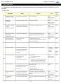
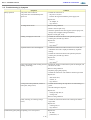
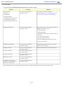
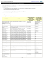
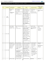
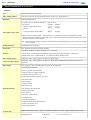
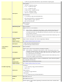
1-1. Adjustment, Periodic Maintenance, Periodic Replacement Parts, and Replacement Consumables by Service
Engineer
(1) Adjustment
Adjustment
Timing
Destination settings
(EEPROM settings)
- At logic board replacement
EEPROM
initialization
- At logic board replacement
Ink absorber counter
resetting
- At logic board replacement
Purpose
To set destination.
To initialize settings
To reset the ink absorber counter.
- At ink absorber replacement
- At logic board replacement
1 min.
None.
1 min.
To set the ink amount data in the ink
absorber to the ink absorber counter.
None.
None.
2 min.
- At logic board replacement
- Computer
(MP driver)
Manual:
5 min.
- When print quality is not
satisfying
- Machine
button
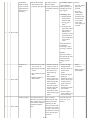
- At paper feed motor
replacement
To adjust the belt tension.
Print head alignment
- At print head replacement
To secure the dot placement accuracy.
- At logic board replacement
- At feed roller ass'y
replacement
- At platen unit replacement
Grease application
None.
Perform in the
service mode.
Paper feed motor
position adjustment
New
1 min.
Perform in the
service mode.
(EEPROM settings)
LF / Eject correction
None.
Approx.
time
Perform in the
service mode.
(EEPROM settings)
Ink absorber counter
value setting
Tool
- At carriage unit replacement
- At PR shaft ass'y replacement
- At CL base or CL gear
replacement
1 min.
Perform in the
service mode.
(Position the paper feed motor so that the
belt is stretched tight.)
LF correction:
To correct line feeding
Eject correction:
None.
Auto: 4
min.
5 min.
Perform in the
service mode.
To adjust eject rollers and maintain the
paper eject accuracy using the eject
encoder for the trailing edge of paper
To maintain sliding properties of the
following items:
FLOIL KG107A
1 min.
To maintain detection functionality for
presence of the ink tanks and each ink tank
position.
None.
1 min.
To set the language to be displayed on the
LCD.
None.
- Carriage shaft
- Lift cam bushing
- Machine sliding portions (gears)
Ink system function
check
- At logic board replacement
- At platen unit replacement
- At carriage unit replacement
LCD language
settings
- At logic board replacement
1-1
Perform in the
service mode.
Perform in the
user mode.
1 min.
Document pressure
sheet position
adjustment
- At document pressure sheet
replacement
To adjust the pressure sheet to fit in place to None.
the four corners of the platen glass when the
cover is closed.
1 min.
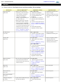
Caution: DO NOT loosen the red screws at both ends of the carriage shaft, securing the print head position, as they are not readjustable.
The red screws securing the paper feed motor may be loosened only at replacement of the paper feed motor unit..
(2) Periodic maintenance
No periodic maintenance is necessary.
(3) Periodic replacement parts
There are no parts in this machine that require periodic replacement by a service engineer.
(4) Replacement consumables
There are no consumables that require replacement by a service engineer.
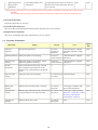
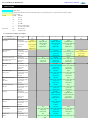
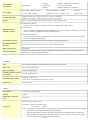
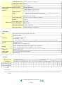
1-2. Customer Maintenance
Adjustment
Timing
Purpose
Tool
Approx.
time
Print head
alignment
At print head replacement
To ensure
accurate dot
placement.
- Machine buttons- Computer
(automatic alignment via MP
driver)
4 min.
Print head cleaning
When print quality is not satisfying.
To improve
- Machine buttons- Computer
nozzle conditions. (MP driver)
1 min.
Print head deep
cleaning
When print quality is not satisfying, and not
improved by print head cleaning.
To improve
- Machine buttons- Computer
nozzle conditions. (MP driver)
2 min.
Ink tank
replacement
When an ink tank becomes empty. ("No ink
error" displayed on the monitor or on the
machine LCD, or short flashing of an ink tank
LED)
―
2 min.
Paper feed roller
cleaning
When paper does not feed properly.
To clean the paper - Machine buttons
feed rollers.
2 min.
Bottom plate
cleaning
When the back side of the paper is smeared.
To clean the
platen ribs.
1 min.
ASF sub- roller
cleaning
When the paper fed from the ASF is smeared due To clean the ASF
to ink mist attached to the ASF sub-rollers.
sub-rollers.
- Plain paper- Machine buttons
1 min.
See Part 2, 4. FAQ, How to make
and set the ASF sub-roller
cleaning sheet, for details.
Scanning area
cleaning
When the platen glass is dirty.
None.
To clean the
platen glass.
1-2
―
- Plain paper- Computer (MP
driver)- Machine buttons
1 min.
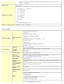
1-3. Product Life
(1) Machine
Specified print volume (I) or the years of use (II), whichever comes first.
(I) Print volume: 24,000 pages
Black
1500 character pattern
11,000 pages
Color
7.5% duty per color pattern
7,200 pages
A4, photo, borderless printing
500 pages
4 x 6, photo, borderless printing
4,300 pages
Postcard, photo, borderless printing
1,000 pages
(II) Years of use: 5 years of use
(2) Print head
Print volume: 33,600 pages
(3) Ink tank (target value)
Average yield
( ): Estimated supplemental yield
Color document (ISO/IEC FCD24712)*1
Photo (4" x 6")*2
PGI-5BK
CLI-8BK
CLI-8C
CLI-8M
CLI-8Y
520 pages
(5,220) pages
890 pages
670 pages
700 pages
(3,095) pages
(1,305) pages
387 pages
271 pages
291 pages
*1: Declared yield value in accordance with ISO/IEC FCD24711. Values obtained by continuous printing.
*2: When printing Canon standard patterns on 4" x 6" Photo Paper Plus Glossy continuously with the default settings of Photo Paper
Plus Glossy using Windows XP printer driver in borderless printing mode and Windows XP Photo Printing Wizard. Declared yield
value determined based on Canon standard method referring to ISO/IEC FCD24712.
Note: Ink yield may vary depending on texts/photos printed, applications software used, print mode and type of paper
used.
1-4. Special Tools
Name
Tool No.
FLOIL KG-107A QY9-0057-000
Price
(JPY)
210
Application
To the carriage shaft sliding portions, and lift cam
bushing
Remarks
In common with the
S520.
1-5. Serial Number Location
On the carriage flexible cable holder (visible on the left of the carriage: open the scanning unit after turning off the machine.)
<1-1. MAINTENANCE>
1-3
Part 1: MAINTENANCE
TABLE OF CONTENTS
2. LIST OF ERROR DISPLAY / INDICATION
Errors and warnings are displayed by the following ways:
1) Operator call errors are indicated by the Alarm LED lit in orange, and the error and its solution are displayed on the LCD in
text and by icon.
2) Messages during printing from a computer are displayed on the MP driver Status Monitor.
3) Error codes are printed in the "operator call/service call error record" area in EEPROM information print.
Buttons valid when an operator call error occurs:
1) ON/OFF button: To turn the machine off and on again.
2) OK button: To clear and recover from an error. In some operator call errors, the error will automatically be cleared when
the cause of the error is eliminated, and pressing the OK button may not be necessary.
3) Stop/Reset button: To cancel the job at error occurrence, and to clear the error.
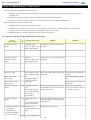
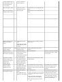
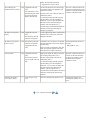
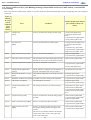
2-1. Operator Call Errors (by Alarm LED Lit in Orange)
Error
[Error code]
U
No.
No paper in the ASF.
[1000]
---
No paper in the front
paper feed cassette.
[1003]
---
Paper jam. [1300]
---
Paper jam in the rear
guide. [1303]
---
Paper jam in the under
guide. [1304]
---
Ink may have run out.
[1600]
Message on the LCD
Auto sheet feeder.
There is no paper. Load
paper and press [OK].
Cassette.
There is no paper. Load
paper and press [OK].
U041 (Applicable ink tank
icon)
U043 (Applicable ink tank
icon)
The following ink tank
cannot be recognized.
- Print head not installed,
or not properly
installed. [1401]
Remarks
Set the paper in the ASF, and press the
OK button.
Set the paper in the cassette, and press the
OK button.
Paper output slot / Rear Remove the jammed paper, and press the Error during paper feeding from
cover / Duplex transport OK button.
the ASF
unit.
Error in the duplexing transport
The paper is jammed.
unit
Clear the paper and
Error during paper feeding from
press [OK].
the cassette
The following ink may
have run out. Replacing
the ink tank is
recommended.
Ink tank not installed.
[1660]
Solution
Replace the applicable ink tank, or press
the OK button to clear the error without
ink tank replacement.
Install the applicable ink tank(s) properly,
and confirm that the LED's of all the ink
tanks light red.
U051 Print head is not
Install the print head properly.
installed. Install the print
head.
- Print head temperature
sensor error. [1403]
U052 The type of print head is
1-4
When the error is cleared by
pressing the OK button, ink may
run out during printing.
- Faulty EEPROM data of
the print head. [1405]
incorrect. Install the
correct print head.
- Print head hardware
error. [1682]
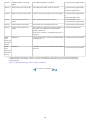
Inner cover open. [1841]
---
Inner cover open during
printing on paper. [1846]
---
Inner cover is open.
Close the inner cover
and press [OK].
Multiple ink tanks of the
same color installed.
[1681]
U071 (Applicable ink tank
icon)
Ink tank in a wrong
position. [1680]
U072 Some ink tanks are not
installed in place.
Close the inner cover, and press the OK
button.
Close the inner cover, and press the OK
button.
Replace the wrong ink tank(s) with the
correct one(s).
More than one ink tank
of the following color is
installed.
Install the ink tank(s) in the correct
position.
Warning: The ink
absorber becomes almost
full. [1700, 1701 (Japan)]
---
Contact the support
Press the OK button.
center or service center
for ink absorber
replacement. Press [OK]
to continue printing.
The connected digital
camera or digital video
camera does not support
Camera Direct
Printing. [2001]
---
The device may be
Remove the cable between the camera
incompatible. Remove
and the machine.
the device and check the
manual supplied with
the connected device.
Automatic duplex
printing cannot be
performed. [1310]
---
This paper is not
compatible with duplex
printing. Remove the
paper and press [OK].
Failed in automatic print
head alignment. [2500]
---
Auto head align has
Press the OK button.
failed.
- If paper is being fed at error occurrence,
Press [OK] and repeat
the error is indicated after the paper is
operation. <See manual> ejected.
Press the OK button to eject the paper
being used at error occurrence. Printing
will resume from on the front side of the
next page.
- If the error occurs, the print head
alignment values are not changed.
- After exit from the error by the OK
1-5
The service call error, indicating
the ink absorber is full, is likely
to occur soon.
Data which was to be printed on
the back side of paper at error
occurrence is skipped (not
printed).
The error will occur (a) when
the print head alignment pattern
is not printed due to no ink or
non-ejection of ink, (b) when the
sensor's AD value is incorrect,
or (c) when the paper is shorter
than the specified length.
button, the automatic print head
alignment will not be re-done.
The remaining ink
amount unknown. [1683]
U130 (Applicable ink tank
icon)
An ink tank which has once been empty
is installed. Replace the applicable ink
tank with a new one.
The remaining level of
the following ink cannot Printing with a once-empty ink tank can
be correctly detected.
damage the printer.
Replace the ink tank.
To continue printing without replacing
the ink tank(s), press the Stop/Reset
button for 5 sec. or longer to disable the
function to detect the remaining ink
amount. After the operation, it is
recorded in the printer EEPROM that the
function to detect the remaining ink
amount was disabled.
Ink tank not recognized.
[1684]
U140 (Applicable ink tank
icon)
The following ink tank
cannot be recognized.
Ink tank not recognized.
[1410 to 1419]
U150 The following ink tank
cannot be recognized.
(Applicable ink tank
icon)
No ink. [1688]
Scanning unit (printer
cover) open. [1200]
U163 (Applicable ink tank
icon)
---
The error is indicated when raw
ink is detected but the dot count
number exceeds the threshold of
complete exhaustion of ink.
A non-supported ink tank is installed (the
ink tank LED is turned off). Install the
supported ink tanks.
A hardware error occurred in an ink tank Ink tank positioning (from left
(the ink tank LED is turned off). Replace to right):
the ink tank(s).
BK, PigBK, Y, M, C
Each error code corresponds to each ink
tank, from left (the opposite side of the
home position) to right, respectively.
Replace the empty ink tank(s), and close
the scanning unit (printer cover).
The following ink has
run out. Replace the ink
tank.
Printing with an empty ink tank can
damage the printer.
Cover is open. Close
cover.
Close the scanning unit (printer cover).
To continue printing without replacing
the ink tank(s), press the Stop/Reset
button for 5 sec. or longer to disable the
function to detect the remaining ink
amount. After the operation, it is
recorded in the printer that the function to
detect the remaining ink amount was
disabled.
<1-2-1. Operator Call Errors>
1-6
The error is indicated when "no
raw ink" is detected and when
the dot count number exceeds
the threshold of complete
exhaustion of ink.
Printing stops because the
scanning unit (printer cover) is
open.
Part 1: MAINTENANCE
TABLE OF CONTENTS
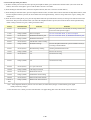
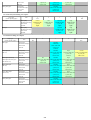
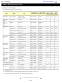
2-2. Service Call Errors (by Cyclic Blinking in Orange (Alarm LED) and Green (COPY button), or Alarm LED
Lit in Orange)
Service call errors are indicated by the number of cycles the Alarm LED and COPY button blink, and the corresponding error code is displayed
on the LCD.
Cycles of
blinking
in orange
(Alarm
LED) and
green
(COPY
button)
Error
Conditions
Solution (Replacement of listed
parts, which are likely to be
faulty)
2 times
Carriage error
[5100]
An error occurred in the carriage encoder signal.
- Carriage unit (QM2-3936)
- Timing slit strip film (QC16526)
- Logic board ass'y (QM3-0250)*1
- Carriage motor (QK1-1500)
3 times
Line feed error
[6000]
An error occurred in the LF encoder signal.
- Timing sensor unit (QM3-1271)
- Timing slit disk film (QC20475)
- Feed roller ass'y (QL2-1490)
- Logic board ass'y (QM3-0250)*1
- Paper feed motor (QK1-1502)
4 times
Purge cam sensor error [5C00]
An error occurred in the purge unit.
- Purge unit (QM3-0033)
- Logic board ass'y (QM3-0250)*1
5 times
ASF (cam) sensor error [5700]
This error takes place when feeding paper from the
ASF after an error occurred in the ASF cam sensor.
- Sheet feed unit (QM3-0064)
6 times
Internal temperature error [5400]
The internal temperature is not normal.
- Logic board ass'y (QM3-0250)*1
- Carriage unit (QM2-3936)
7 times
Ink absorber full [5B00, 5B01
(Japan)]
The ink absorber is supposed to be full.Message on
the LCD: Ink absorber full. Service required.
- Ink absorber kit (QY5-0181)
8 times
Print head temperature rise error
[5200]
The print head temperature exceeded the specified
value.
- Print head (QY6-0061)
- Logic board ass'y (QM3-0250)*1
9 times
EEPROM / NVRAM error [6800] A problem occurred in writing to the EEPROM.
- Logic board ass'y (QM3-0250)*1
10 times
VH monitor error [B200]
The VH output is not normal.
- Print head (QY6-0061)
- Logic board ass'y (QM3-0250)*1
11 times
Carriage lift mechanism error
[5110]
The carriage did not move up or down properly.
- PR lift shaft ass'y (QL2-1450)
- Sheet feed unit (QM3-0064)
- Logic board ass'y (QM3-0250)*1
- Carriage lift sensor unit (QM31273)
12 times
AP position error [6A00]
An error occurred in the AP motor during purging
operation.
- Sheet feed unit (QM3-0064)
- Logic board ass'y (QM3-0250)*1
- Purge unit (QM3-0033)
13 times
Paper feed position error [6B00]
An error occurred in the paper feed motor.
- Sheet feed unit (QM3-0064)
- Logic board ass'y (QM3-0250)*1
14 times
Paper feed cam sensor error
[6B10]
An error occurred in the paper feed cam sensor
during paper feeding from the front paper feed
cassette.
This error is also indicated when the ink absorber
counter value is 60% or more, and a paper jam
occurs in the under guide.
- Sheet feed unit (QM3-0064)
- Logic board ass'y (QM3-0250)*1
1-7
15 times
USB Host VBUS overcurrent
[9000]
The USB Host VBUS is overloaded.
- Logic board ass'y (QM3-0250)*1
16 times
Pump roller sensor error [5C20]
The pump roller position cannot be detected.
- Logic board ass'y (QM3-0250)
*1
- Purge unit (QM3-0033)
17 times
Paper eject encoder error [6010]
An error occurred in the paper eject encoder signal.
- Logic board ass'y (QM3-0250)
*1
- Platen unit (QM3-1794)
19 times
Ink tank position sensor error
[6502]
None of the ink tank position is detected.
- Platen unit (QM3-1794)
- Logic board ass'y (QM3-0250)*1
20 times
Other hardware error [6500]
The PCI bus error is detected by the ASIC.
- Logic board ass'y (QM3-0250)*1
22 times
Scanner home position error
[5010]
The scanner unit cannot detect the home position, or - Scanner unit (QM2-3940)
the scanner unit warming-up is not performed
properly at power-on.
On the LCD, "Scanner is not operating correctly." is
displayed.
- Logic board ass'y (QM3-0250)*1
Power
ROM error
LED
turned off,
and Alarm
LED lit
The check sum value is incorrect in the ROM check
at hard-power-on.
Power
RAM error
LED
turned off,
and Alarm
LED lit
The RAM error occurred in the RAM check at hard- - Logic board ass'y (QM3-0250)*1
power-on.
*1: Before replacement of the logic board ass'y, check the ink absorber counter value (by service test print or EEPROM
information print). If the counter value is 7% or more, also replace the ink absorber kit (QY5-0181) when replacing the
logic board ass'y.
[See 3-3. Adjustment / Settings, (5) Service mode, for details.]
<1-2-2. Service Call Errors>
1-8
Part 1: MAINTENANCE
TABLE OF CONTENTS
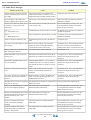
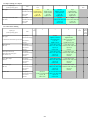
2-3. Other Error Messages
Message on the LCD
The selected paper cannot be fed from
cassette. Change the paper source and
press [OK].
Cause
The paper type being used (business card,
Credit Card size paper, or stickers, etc.) is not
supported for paper feeding from the cassette.
Solution
Change the paper source to the ASF.
Device memory is full. Reduce the
The memory is not sufficient to do the print
amount of photos, films, copies to scan. job.
Reduce the amount of data to be printed, or
print from a computer.
Failed to scan. Either document cannot
be scanned or is not placed on the
platen glass.
The machine failed in scanning the document
for Fit-to-page copy.
Press the OK button to clear the error. The
LCD automatically returns to the display
before the error occurrence.
Press <>.
(<>: Color button icon)
The Black button was pressed, but it is invalid. A temporary error. Press the Color button to
continue the operation.
Press <>.
(<>: Black button icon)
The Color button was pressed, but it is invalid. A temporary error. Press the Black button to
continue the operation.
There are no photos in memory card.
Supported image files are not in the memory
card.
A temporary error.
The value exceeds the number of copies During selecting images or specifying the
you can print.
number of copies, the total print quantity
exceeds the prescribed value of 999.
A temporary error. The last operation before
the error is cancelled, and the total print
quantity returns to the value before the error.
Memory card is not set. Insert the card
after checking the direction.
No memory card is inserted in the slot.
Set a memory card.
DPOF information is not saved in the
memory card.
DPOF print was selected in the menu, but no
DPOF files are contained in the memory card.
A temporary error. The LCD automatically
returns to the display before the error
occurrence.
This layout is available only for A4 or
8.5"x11"(215x279).
In Layout print, "Mixed 1, 2, or 3" which is
available only with A4 or Letter size paper is
selected, but the paper size is not set to A4 or
Letter.
A temporary error. The LCD automatically
returns to the display before the error
occurrence.
Change the setting after removing the
card.
With a memory card inserted in the slot,
change of the Read/Write attribute was
attempted.
A temporary error. The LCD automatically
returns to the display before the error
occurrence.
The card is currently write-enabled. Set With the memory card set to the Read/write
to read-only mode before performing
mode, Card Direct printing operation was
operation.
attempted from the menu.
A temporary error. The LCD automatically
returns to the display before the error
occurrence.
The paper size is not correct. Check the Non-supported size of paper for Camera Direct Cancel printing on the digital camera.
page size you have set.
printing is selected.
Failed to scan handwriting sheet. Check The machine failed in scanning the
for missed and improper markings.
handwritten Photo Index Sheet.
Press the OK button to clear the error. The
LCD automatically returns to the display
before the error occurrence.
Failed to scan handwriting sheet. Check The machine failed in scanning the
orientation and position, and make sure handwritten Photo Index Sheet.
platen and sheet are clean. <See
manual>
Press the OK button to clear the error. The
LCD automatically returns to the display
before the error occurrence.
Failed to scan Photo Index Sheet.
Check for missed and improper
markings.
The machine failed in scanning the Photo
Index Sheet.
Press the OK button to clear the error. The
LCD automatically returns to the display
before the error occurrence.
Failed to scan Photo Index Sheet.
Check the orientation, position and
marking. <See manual>
The machine failed in scanning the Photo
Index Sheet.
Press the OK button to clear the error. The
LCD automatically returns to the display
before the error occurrence.
<1-2-3. Other Error Messages>
1-9
Part 1: MAINTENANCE
TABLE OF CONTENTS
2-4. Warnings
Warning
Low ink
Message on the LCD
Solution
The following ink is low. Continue?
- Select Yes, and press the OK button.
(Icon of each ink tank)
Yes
=> Printing starts, and it is indicated on the LCD.
No
- Select No, and press the OK button.
In Camera Direct Printing, only "Yes" can be
selected.
Print head temperature
rise
=> Printing is cancelled, and the LCD returns to
the display immediately before printing was
attempted.
If the print head temperature does not fall, the error
code "5200" is displayed, indicating the print head
temperature rise error.
When the print head temperature falls, the error is
automatically cleared.
Protection of excess rise
of the print head
temperature
If the print head temperature does not fall, the error
code "5200" is displayed, indicating the print head
temperature rise error.
If the print head temperature exceeds the specified
limit, an intermission is inserted during printing.
Restrictions on paper
The current paper cannot be set. Change the size and
type.
Re-select the supported paper type and size.
Recommendation of the
print head alignment
(only on arrival of the
machine)
Head alignment required. Load paper and press [OK]. - Select Yes, and press the OK button.
Yes
No
Note: If the print head temperature exceeds the
specified limit when the scanning unit (printer
cover) is opened, the carriage does not move
to the ink tank replacement position.
=> Automatic print head alignment is performed.
- Select No, and press the OK button.
=> The procedures on arrival of the machine are
finished.
USB cable not connected
Connect USB cable and turn on the PC.
Connect the USB cable.
Cancellation of image
select information
Reset the selected photo information?
When one or more images are selected in Multi-photo
print or Layout print, and if a user tries to display the
menu or sub-menu, the message is displayed.
Yes
- Select Yes, and press the OK button.
=> The image selection is cancelled, and the menu
or sub-menu is displayed.
<1-2-4. Warnings>
1-10
Part 1: MAINTENANCE
TABLE OF CONTENTS
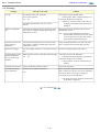
2-5. Troubleshooting by Symptom
Symptom
Faulty operation
Solution
The power does not turn on.
- Confirm the connection of
The power turns off immediately after
power-on.
- the power cord, and
- between the logic board and the power supply unit.
- Replace the
- AC adapter, or
- logic board*1.
A strange noise occurs.
- Remove foreign material.
- Attach a removed part if any.
- Check the operation of the moving parts (such as purge unit,
carriage unit, and paper feeding mechanism)
- Replace a faulty part, if any.
Nothing is displayed on the LCD.
- Confirm the connection between the operation panel, the
scanning unit, and the logic board.
- Replace the
- LCD, or
- logic board*1.
A portion of the LCD is not displayed.
- Perform the button and LCD test in the service mode, and
confirm that the LCD is displayed without any segments
missing.
- Confirm the connection between the operation panel, the
scanning unit, and the logic board.
- Replace the
- LCD, or
- logic board*1.
Paper feed problems (multi-feeding, skewed - Examine the inside to confirm that no parts are damaged, and
feeding, no feeding).
the rollers are clean.
- Remove foreign material.
- Adjust the paper guide properly.
- Confirm the connection of each harness and the logic board.
- Replace the
- sheet feeder unit,
- cassette, or
- logic board*1.
Carriage movement problems (contact to
other parts, strange noise).
- Confirm that the timing slit strip film is free from damage or
grease.
- Clean the timing slit strip film.
- Replace the
- timing slit strip film, or
- carriage unit.
- Remove foreign material.
Faulty scanning (no scanning, strange
noise).
- Confirm the connection between the scanning unit and the
logic board.
- Replace the
- scanning unit, or
- logic board*1.
Unsatisfactory print quality No printing, or no color ejected.
- Replace the
- ink tank,
- print head*2, or
1-11
- logic board*1.
- Remove foreign material from the purge unit caps, if any.
- Replace the purge unit.
Printing is faint, or white lines appear on
printouts even after print head cleaning.
Line(s) not included in the print data
appears on printouts.
- Remove and re-install the print head.
- Replace the
- ink tank,
- print head*2,
- purge unit, or
- logic board*1.
Paper gets smeared.
- Feed several sheets of paper.
- Perform bottom plate cleaning.
- Clean the paper path with cotton swab or cloth.
- Clean the ASF sub-rollers.
A part of a line is missing on printouts.
- Replace the
- ink tank, or
- print head*2.
- Perform print head alignment.
Color hue is incorrect.
- Replace the
- ink tank, or
- print head*2.
- Perform print head alignment.
Printing is incorrect.
Replace the logic board*1.
No ejection of black ink.
- Replace the
- ink tank, or
- print head*2.
- Remove foreign material from the purge unit caps, if any.
- Replace the purge unit.
Graphic or text is enlarged on printouts.
When enlarged in the carriage movement direction:
- Clean grease or oil off the timing slit strip film
- Replace the
- timing slit strip film,
- carriage unit, or
- logic board*1.
When enlarged in the paper feed direction:
- Clean grease or oil off the timing slit disk film
- Replace the
- timing slit disk film,
- timing sensor unit, or
- logic board*1.
Faulty scanning
No scanning.
- Confirm the connection between the scanning unit and the logic
board.
- Replace the
- scanning unit, or
- logic board*1.
Streaks or smears on the scanned image.
- Clean the platen glass and the ADF.
- Confirm the connection between the scanning unit and the logic
board.
- Replace the
- scanning unit,
- logic board*1.
1-12
*1: Before replacement of the logic board ass'y, check the ink absorber counter value (by service test print or EEPROM information print). If
the counter value is 7% or more, also replace the ink absorber kit (QY5-0181) when replacing the logic board ass'y.
[See 3-3. Adjustment / Settings, (5) Service mode, for details.]
*2: Replace the print head only after the print head deep cleaning is performed 2 times, and when the problem persists.
<1-2-5. Troubleshooting by Symptom>
1-13
Part 1: MAINTENANCE
TABLE OF CONTENTS
3. REPAIR
3-1. Notes on Service Part Replacement (and Disassembling / Reassembling)
Notes on replacement*1
Adjustment / settings
- Before removal of the logic
board ass'y, remove the power
cord, and allow for approx. 1
minute (for discharge of
capacitor's accumulated
charges), to prevent damages to
the logic board ass'y.
- Before replacement, check the
ink absorber counter value (by
service test print or EEPROM
information print). If the value is
7% or more, also replace the ink
absorber kit (QY5-0181) when
replacing the logic board ass'y.
[See 3-3. Adjustment / Settings,
(5) Service mode, for details.]
After replacement:
1. Initialize the EEPROM.
2. Reset the ink absorber counter.
3. Set the destination in the
EEPROM.
4. Correct the CD / DVD and
automatic print head alignment
sensors.
5. Check the ink system function.
[See 3-3. Adjustment / Settings,
(5) Service mode, for details of 1
to 5.]
6. Perform the print head
alignment in the user mode.
-
Ink absorber kit
QY5-0181
After replacement:
1. Reset the ink absorber counter.
[See 3-3. Adjustment / Settings,
(5) Service mode, for details.]
- Service test print
- EEPROM information print
Carriage unit
QM2-3936
- Service test print (Confirm
At replacement:
1. Apply grease to the sliding
automatic print head
portions.
alignment sensor correction,
[See 3-3. Adjustment / Settings,
and ink system function.)
(2) Grease application.]
After replacement:
1. Correct the automatic print head
alignment sensors.
[See 3-3. Adjustment / Settings,
(5) Service mode, for details.]
2. Check the ink system function.
[See 3-3. Adjustment / Settings,
(5) Service mode, for details.]
3. Perform the print head
alignment in the user mode.
Service part
Logic board ass'y
QM3-0250
Paper feed motor
QK1-1502
Operation check
EEPROM information print
Service test print
Printing via USB connection
Direct printing from a digital
camera
- The red screws securing the paper At replacement:
feed motor are allowed to be
1. Adjust the paper feed motor.
loosened. (DO NOT loosen any
[See 3-3. Adjustment / Settings,
other red screws.)
(1) Paper feed motor
adjustment.]
Platen unit
QM3-1794
After replacement:
1. Check the ink system function.
[See 3-3. Adjustment / Settings,
(5) Service mode, for details.]
- Service test print
PR lift shaft ass'y
QL2-1450
At replacement:
1. Apply grease to the sliding
portions.
[See 3.3. Adjustment / Settings,
(2) Grease application.]
- Service test print
After replacement:
1. Perform the print head
- Service test print
Input carriage lift gear
QC2-1873
Timing slit strip film
QC1-6526
- Upon contact with the film, wipe
the film with ethanol.
1-14
Timing slit disk eject film
QC2-0476
Timing slit disk film
QC2-0475
- Confirm no grease is on the film.
(Wipe off any grease thoroughly
with ethanol.)
alignment in the user mode.
- Do not bend the film
Print head
QY6-0061
After replacement:
1. Perform the print head
alignment in the user mode.
- Service test print
*1: General notes:
- Make sure that the flexible cables and wires in the harness are in the proper position and connected correctly.
[See 3-2. Special Notes on Repair Servicing, (5) Flexible cable and harness wiring, connection, for details.]
- Do not drop the ferrite core, which may cause damage.
- Protect electrical parts from damage due to static electricity.
- Before removing a unit, after removing the power cord, allow the machine to sit for approx. 1 minute (for capacitor discharging to protect
the logic board ass'y from damages).
- Do not touch the timing slit strip film, timing slit disk film, and timing slit disk eject film. No grease or abrasion is allowed.
- Protect the units from soiled with ink.
- Protect the housing from scratches.
- Exercise caution with the red screws, as follows:
i. The red screws of the paper feed motor may be loosened only at replacement of the paper feed motor unit (DO NOT loosen
them in other cases).
ii. DO NOT loosen the red screws on both sides of the main chassis, securing the carriage shaft positioning (they are not
adjustable in servicing)
<1-3-1. Notes on Service Part Replacement>
1-15
Part 1: MAINTENANCE
TABLE OF CONTENTS
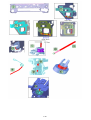
3-2. Special Notes on Repair Servicing
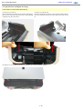
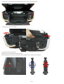
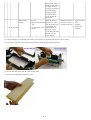
(1) External cover and scanner unit removal
(i) Front cover L removal
Insert a flat-blade screwdriver in the location indicated by
the red circle, and release the front cover L while pushing
it upward using the screwdriver.
(ii) Front cover R removal
Insert the flat-blade screwdriver in the location indicated by the
red circle, and release the front cover R in the same way as step
(i).
(iii) Remove 4 screws from the back of the machine, and 2 screws from the top back.
1-16
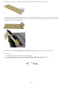
(iv) Remove 2 screws from the front of the machine (1 each on the right and left sides).
(v) Remove the side covers L and R.
(vi) Scanner lock arm unit removal
Push the main case tab outward to unlock the unit.
When assembling the scanner lock arm unit, make sure that the unit is in the correct orientation.
1-17
(vii) Main case removal Remove screws from the right and left sides of the paper ejection side.
Remove screws from the right and left sides of the sheet feeder
side.
1-18
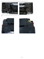
(2) Operation panel and LCD viewer unit removal
(i) Separate the scanner unit from the document cover unit.
(ii) Remove screws from the bottom of the document cover unit.
(iii) Remove screws, and disconnect the flexible cable and
harness.
Harness and core bundled:
(iv) Remove 2 screws from the LCD hinge.
1-19
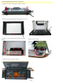
(3) Document pressure sheet replacement Be cautious of the following when replacing the document pressure sheet:
(i) Position one of the corners of the document pressure sheet to the reference mark (indicated by the red arrow below) on
the platen glass.
(ii) Slowly close the document cover unit so that the document pressure sheet will fix to the cover unit with the double-sided
adhesive tape in 4 corners.
(iii) Visually confirm that there is no significant gap between the document cover unit frame and the document pressure
sheet.
1-20
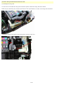
(4) Printer unit separation from the bottom case unit
(i) Unlocking the carriage unit
To remove the screw beneath the carriage unit in the home position, unlock the carriage unit first as follows:
Rotate the gear (indicated by the red square) toward the rear side of the machine 2 or 3 times. The carriage will be unlocked.
(ii) Slide the carriage to the opposite of the home position, and remove the screw.
1-21
(5) Flexible cable and harness wiring, connection
Be cautious of wiring of the flexible cables and harness. Improper wiring or connection may cause breakage of a line,
leading to ignition or emission of smoke.
(i) Logic board ass'y wiring
(ii) Paper feed motor side wiring
<1-3-2. Special Notes on Repair Servicing>
1-22
Part 1: MAINTENANCE
TABLE OF CONTENTS
3-3. Adjustment / Settings
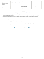
(1) Paper feed motor adjustment
1) When attaching the motor, fasten the screws so that the belt is properly stretched (in the direction indicated by the blue
arrow in the figure below).
2) After replacement, be sure to perform the service test print, and confirm that no strange noise or faulty print operation (due
to dislocation of the belt or gear, or out-of-phase motor, etc.) occurs.
Caution:
The red screws securing the paper feed motor may be loosened only at replacement of the paper feed motor unit. DO NOT loosen them in other
cases.
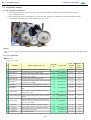
(2) Grease application
■ Printer Unit
1 drop = 9 to 18 mg
No
Part name
Where to apply grease / oil
Drawing
No.
Grease / oil
Grease / oil Number of
amount
drops x
(mg)
locations
1 Chassis ass'y
Entire surface the carriage slider contacts
(1)
Floil KG107A
27 to 54
3x1
2 Adjust plate L
Carriage shaft cam L sliding portion
(2)
Floil KG107A
18 to 36
2x1
3 Chassis ass'y
Carriage shaft sliding portion on the left side of
the chassis (1 location)
(3)
Floil KG107A
9 to 18
1x1
4 Adjust plate R
Carriage shaft cam R sliding portion
(4)
Floil KG107A
18 to 36
2x1
5 Chassis ass'y
Carriage shaft sliding portion on the right side of
the chassis (1 location)
(5)
Floil KG107A
9 to 18
1x1
6 Chassis ass'y
PR lift shaft cam contact portion (3 locations)
(6)
Floil KG107A
18 to 27
1.5 x 3
7 Idler pulley
The shaft surface which contacts the idler pulley
hole
(7)
Floil KG107A
9 to 18
1x1
8 Carriage shaft
Entire surface of the carriage shaft where the
carriage unit slides
(8)
Floil KG107A
200 to 400
(9)
Floil KG107A
9 to 18
1x1
9
Carriage shaft spring Carriage shaft sliding portion (to the end of the
L
spring)
10 Carriage shaft
Carriage shaft surface where the carriage unit
slides (and where the machine-application of the
grease is not feasible)
(10)
Floil KG107A
9 to 18
1x1
11 CL gear base
Outer surface of the CL idle gear R cylinder
(11)
Floil KG107A
9 to 18
1x1
12 CL gear base
Outer surface of the CL output gear cylinder
(12)
Floil KG107A
9 to 18
1x1
13 CL input gear
Joint of the CL gear base
(13)
Floil KG107A
9 to 18
1x1
14 CL input gear
CL input gear teeth
(14)
Floil KG107A
9 to 18
1x1
1-23
1-24
■ Other
1 drop = 9 to 18 mg
No
Part name
Where to apply grease / oil
Drawing
No.
Grease / oil
Grease / oil Number of
amount
drops x
(mg)
locations
1 Jog wheel base
Easy-Scroll Wheel sliding portion
(1)
Floil KG107A
9 to 18
2 Jog wheel
Ring key joint
(2)
Floil KG107A
3
1x4
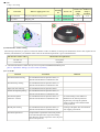
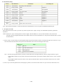
(3) Ink absorber counter setting
When the logic board ass'y is replaced, reset the ink absorber counter. In addition, according to the ink absorber counter value, replace the ink
absorber (ink absorber kit). The standard counter value for ink absorber replacement is given in the table below.
Ink absorber counter value*1
Ink absorber kit replacement
Less than 7%
Not required.
7% or more
Required.
*1: Check the ink absorber counter value by service test print or EEPROM information print.
[See 3-3. Adjustment / Settings, (5) Service mode, for details.]
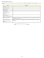
(4) User mode
Function
Print head manual cleaning
Procedures
Remarks
See "Standalone machine operation" below, or
perform from the MP driver Maintenance tab.
Print head deep cleaning
See "Standalone machine operation" below, or
perform from the MP driver Maintenance tab.
Paper feed roller cleaning
See "Standalone machine operation" below.
Nozzle check pattern printing
See "Standalone machine operation" below, or
perform from the MP driver Maintenance tab.
Print head alignment
(automatic / manual)
See "Standalone machine operation" below, or
Bottom plate cleaning
See "Standalone machine operation" below, or
perform from the MP driver Maintenance tab.
perform from the MP driver Maintenance tab.
Print head replacement
The print head is replaceable at the same position
as for ink tank replacement. (Open the scanning
unit. When the carriage stops at the center, the print
head can be replaced.)
1-25
In Custom Settings of the MP driver
Maintenance tab, manual print head
alignment (by selecting the optimum
values) as with the conventional models
can be performed.
Cleaning of the platen ribs when the back
side of paper gets smeared.
<Standalone machine operation>
Turn on the machine. On the operation panel, press the HOME button, select Settings, and Maintenance or Device settings, then a desired
function.
Menu
Remarks
Cleaning
Nozzle check pattern
Deep cleaning
Roller cleaning
Auto head align
(automatic print head
alignment)
Manual head align
(manual print head alignment)
Bottom plate cleaning
Fold a sheet of A4 or Letter size plain paper in half, then open it. Set the paper in the ASF with
the opened surface facing up.
Prevent paper abrasion
Press the HOME button. Select Settings, Device settings, Print settings, then Prevent paper
abrasion.
(Increase the head-to-paper
distance.)
<1-3-3,Adjustment / Settings (1)~(4) >
1-26
Part 1: MAINTENANCE
TABLE OF CONTENTS
(5) Service mode
A: Service test print, EEPROM initialization, Ink absorber counter resetting
Function
Service test print
- Model name
Procedures
Remarks
See "Service mode operation
procedures" below.
Set a sheet of A4 or letter size paper.
See "Service mode operation
procedures" below.
The following items are NOT initialized, and the
shipment arrival flag is not on:
- ROM version
For print sample, see 3-4. Verification Items, (1)
Service test print, <Service test print sample>.
- USB serial number
- Ink absorber counter value (ink
amount in the ink absorber)
- Ink system function check result
EEPROM initialization
- USB serial number
- Destination settings
- Ink absorber counter value (ink amount in the ink
absorber)
- LF / Eject correction value
- Left margin correction value
- Record of disabling the function to detect the
remaining ink amount
Ink absorber counter reset
See "Service mode operation
procedures" below.
If the ink absorber counter value is 7% or more,
replace the ink absorber kit.
Destination settings
See "Service mode operation
procedures" below.
Initialize EEPROM after the destination settings.
LF / Eject correction
See "Service mode operation
procedures" below.
Left margin correction
See "Service mode operation
procedures" below.
Button and LCD test
See "Service mode operation
procedures" below.
Ink absorber counter setting
(registration of the data of the ink
amount in the ink absorber)
See "Service mode operation
procedures" below.
Note: At the end of the service mode, press the ON/OFF button. The paper lifting plate of the sheet feed unit will be raised.
1-27
<Service mode operation procedures>
1) With the machine power turned off, while pressing the Stop/Reset button, press and hold the ON/OFF button. (DO NOT release the
buttons). The Power LED lights in green to indicate that a function is selectable.
2) While holding the ON/OFF button, release the Stop/Reset button. (DO NOT release the ON/OFF button.)
3) While holding the ON/OFF button, press the Stop/Reset button 2 times, and then release both the ON/OFF and Stop/Reset buttons. (Each
time the Stop/Reset button is pressed, the Alarm and Power LEDs light alternately, Alarm in orange and Power in green, starting with
Alarm LED.)
4) When the Power LED lights in green, press the Stop/Reset button the specified number of time(s) according to the function listed in the
table below, then press the ON/OFF button. (Each time the Stop/Reset button is pressed, the Alarm and Power LEDs light alternately,
Alarm in orange and Power in green, starting with Alarm LED.)
Time(s)
LED indication
Function
Remarks
0 times
Green (Power)
Power off
When the print head is not installed, the carriage returns and
locks in the home position capped.
1 time
Orange (Alarm)
Service test print
See 3-4. Verification Items, (1) Service test print.
2 times
Green (Power)
EEPROM information print
See 3-4. Verification Items, (2) EEPROM information print.
3 times
Orange (Alarm)
EEPROM initialization
4 times
Green (Power)
Ink absorber counter resetting
5 times
Orange (Alarm)
Destination settings
Press the Stop/Reset button the specified number of time(s)
according to the destination.
6 times
Green (Power)
Print head deep cleaning
Cleaning of both black and color
7 times
Orange (Alarm)
n/a
Not used in servicing.
8 times
Green (Power)
n/a
Not used in servicing.
9 times
Orange (Alarm)
n/a
Not used in servicing.
10 times
Green (Power)
LF / Eject correction
11 times
Orange (Alarm)
Left margin correction
12 times
Green (Power)
Button and LCD test
13 times
Orange (Alarm)
Ink absorber counter setting
14 times
Green (Power)
Return to the menu selection
15 times or
more
Orange (Alarm)
Return to the menu selection
Note: - If the Stop/Reset button is pressed 16 or more times, the Alarm LED (orange) or COPY button (green) lights
steadily without any changes.
- At the end of the service mode, press the ON/OFF button. The paper lifting plate of the sheet feeder unit will be raised.
1-28
B: Destination settings
Time(s)
LED indication
Destination
CD / DVD print
0 times
Green (Power)
No change of the destination
1 time
Orange (Alarm)
Japan
Supported
2 times
Green (Power)
Korea
Not supported
3 times
Orange (Alarm)
US, CND, LAM
Not supported
4 times
Green (Power)
Europe
Supported
5 times
Orange (Alarm)
Australia
Supported
6 times
Green (Power)
Asia
Supported
7 times
Orange (Alarm)
China
Supported
8 times
Green (Power)
Taiwan
Supported
9 times or
more
Orange (Alarm)
Return to the menu selection
Note: After setting the destination, confirm the model name and destination in service test print or EEPROM information print.
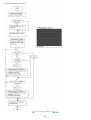
C: LF / Eject correction
After replacement of the LF roller, eject roller, logic board, or platen unit in repair servicing or in refurbishment operation, perform the
adjustment.
Details: Print the LF / Eject correction pattern on a sheet of paper. Select the Pattern No. (0 to 2) in which streaks or lines are the least
noticeable, press the Stop/Reset button the same number of time(s) as the selected Pattern No., then press the ON/OFF button. (See the
flowchart below.)
1) In the LF /Eject correction mode, press the Stop/Reset button the specified number of time(s) according to the paper to be used in LF / Eject
correction listed in the table below, then press the ON/OFF button. (Set a sheet of selected paper in the ASF.)
Time(s) (L)
Paper
1 time
HR-101
2 times
GF-500, Office Planner
3 times
HP BrightWhite
4 times
Canon Extra, STEINBEIS
Note: - Each time the Stop/Reset button is pressed, the Alarm and Power LEDs light alternately, Alarm in orange and Power in green.
- If the Stop/Reset button is NOT pressed, and only the ON/OFF button is pressed, the machine remains in the LF / Eject correction
mode.
- If the Stop/Reset button is pressed 5 times or more, then the ON/OFF button is pressed, the machine returns to the service mode
menu selection.
2) The LF / Eject correction pattern for the selected paper is printed. (LF correction values from 0 to 2, Eject correction values from 0 to 2)
1-29
3) In the printout, select the Pattern No. in which streaks or lines are the least noticeable, press the Stop/Reset button the same number of time
(s) as the selected Pattern No., then press the ON/OFF button.
1-30
3-1) LF correction value
Selected pattern number
Number of times the Stop/Reset button is pressed
(M)
1
1 time
0
0 times
2
2 times
Note: - Each time the Stop/Reset button is pressed, the Alarm and Power LEDs light alternately, Alarm in orange and Power in green.
- If the Stop/Reset button is pressed 3 times or more, then the ON/OFF button is pressed, the machine returns to the service mode
menu selection.
3-2) Eject correction value
Selected pattern number
Number of times the Stop/Reset button is pressed
(N)
1
1 time
0
0 times
2
2 times
Note: - Each time the Stop/Reset button is pressed, the Alarm and Power LEDs light alternately, Alarm in orange and Power in green.
- If the Stop/Reset button is pressed 3 times or more, then the ON/OFF button is pressed, the machine returns to the service mode
menu selection.
4) The selected LF correction value or Eject correction value is written to the EEPROM. The machine returns to the service mode menu
selection after the Eject correction value is written to the EEPROM.
1-31
<1-3-3, (5) Service mode_A~C>
1-32
Part 1: MAINTENANCE
TABLE OF CONTENTS
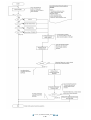
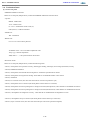
D: Left margin correction
Adjust the left margin for duplex printing or printing from the cassette.
1) Duplex printing from the ASF and cassette
In the left margin correction mode, press the Stop/Reset button 1 time, then press the ON/OFF button 1 time. Duplex printing is performed
from the ASF and cassette.
Number of times the
Stop/Reset button is
pressed (L)
Operation
0 times
No operation
1 time
Duplex printing from the ASF and cassette
2 times
Return to the service mode menu selection (no writing to the
EEPROM)
From each paper source (ASF and cassette), 2 sheets of paper are ejected. The first sheet is blank, and the left margin correction pattern is
printed on the second sheet.
<Printing sequence>
For detail, see the flowcharts below.
i) A sheet of paper feeds from the ASF, and ejected blank (single-sided printing).
ii) A sheet of paper feeds from the ASF. Nothing is printed on the front side, and the pattern is printed on the back side (duplex printing).
iii) A sheet of paper feeds from the cassette, and ejected blank (single-sided printing).
iv) A sheet of paper feeds from the cassette. The pattern is printed on both sides of paper (duplex printing).
A total of 4 sheets are ejected.
After this, set the correction value to the EEPROM in the steps below.
2) Selection of the parameter mode for left margin correction
Press the Stop/Reset button the specified number of time(s) according to the parameter mode listed in the table below, then press the
ON/OFF button.
Each time the Stop/Reset button is pressed, the Alarm and Power LEDs light alternately, Alarm in orange and Power in green.
Number of times the
Stop/Reset button is
pressed (M)
Parameter mode
0 times
Duplex printing from the ASF and cassette
1 time
Back side of paper fed from the ASF
2 times
Front side of paper fed from the cassette
3 times
Back side of paper fed from the cassette
4 times or more
Return to the service mode menu selection (after writing to the
EEPROM)
1-33
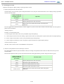
3) Setting of the left margin correction value ("+" means to increase the left margin)
Press the Stop/Reset button the specified number of time(s) according to the correction value listed in the table below, then press the
ON/OFF button.
Number of times the
Stop/Reset button is
pressed (N)
Left margin correction value
0 times
Return to the parameter mode selection for left margin correction
1 time
+1 pitch
2 times
+2 pitches
3 times
+3 pitches
4 times
-1 pitch
5 times
-2 pitches
6 times
-3 pitches
7 times or more
Return to the service mode menu selection (no writing to the
EEPROM)
After the value is set, the machine returns to the parameter mode selection. Repeat steps 2) and 3) to adjust the left margin in each
parameter mode: "back side of paper fed from the ASF," "front side of paper fed from the cassette," and "back side of paper fed from the
cassette."
4) After the left margin correction in all the parameter modes is completed, press the Stop/Reset button 4 times or more in the
parameter mode selection, then press the ON/OFF button to return to the service mode menu selection.
1-34
1-35
1-36
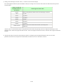
E: Ink absorber counter setting
Set the ink absorber counter value to a replaced new EEPROM after the logic board is replaced in servicing.
1) Before replacement of the logic board ass'y, check the ink absorber counter value in EEPROM information print.
See 3-4. Verification Items, (2) EEPROM information print.
2) In the ink absorber counter setting mode, press the Stop/Reset button the specified number of time(s) according to the ink absorber
whose counter value should be transferred to the replaced new EEPROM. (Only the main ink absorber for the MP600)
Time(s)
Ink absorber
Remarks
0 times
Main ink absorber
1 time
Platen ink absorber
Not valid for the MP600
2 times
Both the main and platen ink absorbers
Only the main ink absorber is valid for the MP600
Not valid
Press the ON/OFF button to return to the ink absorber
counter setting mode.
3 times or
more
3) Press the ON/OFF button to proceed to the next step.
4) The ink absorber counter value can be set in 10% increments by pressing the Stop/Reset button. Press the Stop/Reset button the
appropriate number of time(s) to select the value which is closest to the actual ink absorber counter value.
Time(s)
Ink absorber counter value to be set (%)
0 times
0%
1 time
10%
2 times
20%
3 times
30%
4 times
40%
5 times
50%
6 times
60%
7 times
70%
8 times
80%
9 times
90%
10 times or more
Not valid.
Press the ON/OFF button to return to the ink absorber counter setting mode.
5) Press the ON/OFF button to set the selected value to the EEPROM. Print EEPROM information to confirm that the value is
properly set to the EEPROM.
1-37
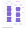
F: Button and LCD test
Confirm the operation after replacement of the operation panel unit, board, or LCD unit.
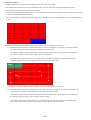
1) In the button and LCD test mode, press the Stop/Reset button. The LCD turns blue, waiting for a button to be pressed.
2) Press each button of the operation panel (total 17 buttons).
3) Only one button should be pressed at one time. If 2 or more buttons are pressed at the same time, only one of them is considered to
be pressed, and the other buttons are ignored.
The LCD is divided into segments, representing each button. The color of a segment corresponding to the pressed button changes
to red.
4) Rotate the Easy-Scroll Wheel clockwise and counterclockwise 1 round (24 steps) each, as follows:
4-1) Rotate the Easy-Scroll Wheel clockwise step by step. The LCD is divided into 24 segments, representing each step.
The color of a segment corresponding to the step changes from red to green.
If the wheel is rotated counterclockwise before clockwise round completes, the color of segment(s) corresponding to
the number of steps the wheel is rotated counterclockwise returns to red.
If the wheel keeps rotated clockwise over 1 round (24 steps), the color of segment(s) corresponding to the extra
number of steps returns to red, starting with the "Start" segment in the figure below.
4-2) When the Easy-Scroll Wheel is rotated clockwise 1 round (24 steps), press the OK button.
4-3) Rotate the Easy-Scroll Wheel counterclockwise step by step. The LCD is divided into 24 segments, representing each
step. The color of a segment corresponding to the step changes from green to blue.
If the wheel is rotated clockwise before counterclockwise round completes, the color of segment(s) corresponding to
the number of steps the wheel is rotated clockwise returns to green.
If the wheel keeps rotated counterclockwise over 1 round (24 steps), the color of segment(s) corresponding to the
extra number of steps returns to green, starting with the "Start" segment in the figure below.
1-38
4-4) When the Easy-Scroll Wheel is rotated counterclockwise 1 round (24 steps), press the OK button. The color of all
segments turns red.
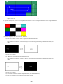
5) Open the scanning unit (printer cover) to display the color pattern. If there is any step left un-selected (a blue segment remained in
step 4) above), even the Stop/Reset button is not accepted.
6) Adjust the transparent color and LCD flicker, as follows:
6-1) Press the OK button. "OK1" in white is displayed on the black background.
If the result is not good, "NG1" in black is displayed on the white background (transparent color) immediately after
"OK1."
6-2) Press the OK button.
6-3) "OK2" in black is displayed on the white background.
If the result is not good, "NG2" in white is displayed on the black background (transparent color) immediately after
"OK2."
6-4) Press the OK button.
6-5) The machine enters the LCD flicker adjustment mode. (See the flowchart below.)
6-6) Press the ON/OFF to return to the service mode menu selection.
1-39
<Flicker adjustment mode flowchart>
<1-3-3, (5) Service mode_D~F>
1-40
Part 1: MAINTENANCE
TABLE OF CONTENTS
3-4. Verification Items
(1) Service test print
<EEPROM information contents>
On the service test print (sample below), confirm the EEPROM information as shown below.
- Top area:
MP600: Model name
Vx.xx: ROM version
D = xxx.x: Ink absorber counter value (%)
USB (xxxxxx): USB serial number
- Middle area:
JPN: Destination
- Bottom area:
FA=xx xx xx: Reserved for plant use
VrefPWM=xxxxx: TFT LCD flicker adjustment value
Temp.=yyy: Internal temperature
AB(K=OK Y=....): Ink system function check result
<Print check items>
On the service test print (sample below), confirm the following items:
- Check 1, check pattern for top of form accuracy, skewed paper feeding, left margin, and carriage (outermost) accuracy
- Check 2, EEPROM information
- Check 3, check pattern for horizontal dot mis-alignment: Ink shall be ejected from all nozzles.
- Check 4, check pattern for irregular line feeding: There shall be no remarkable streaks or unevenness.
- Check 5, destination
- Check 6, LF correction value (The value selected in the LF correction is printed in cyan)
- Check 7, check pattern for LF correction (the check pattern selected in the LF correction)
- Check 8, check pattern for uneven printing due to carriage movement (9600 dpi mode): There shall be no remarkable unevenness.
- Check 9, check pattern for uneven printing due to carriage movement (standard mode): There shall be no remarkable unevenness.
- Check 10, check pattern for straight line accuracy: There shall be no remarkable dot mis-alignment on a line.
- Check 12, check pattern for Eject correction (the check pattern selected in the Eject correction)
- Check 13, Eject correction value (The value selected in the Eject correction is printed in magenta)
1-41
<Service test sample>
<1-3-4, (1) Service test print>
1-42
Part 1: MAINTENANCE
TABLE OF CONTENTS
3-4. Verification Items
(2) EEPROM information print
<How to read EEPROM information print>
Print sample:
MP600 JPN V1.00 ST=2006/06/15-18:30 LPT=2006/07/09-09:09
ER(ER0=1000 ER1=5100) P_ON(S=00009) MSD(002)
IF(USB1=1) PC(M=002 R=000 T=001 D=009 C=000)
D=004.5
TPAGE(TTL=00232 COPY=00001)
CLT(BK=2006/06/28-18:30 CL=2006/07/01-18:30)
CH=001 CT(PBK=001 BK=001 Y=003 M=002 C=001)
IS(PBK=0 BK=0 Y=0 M=0 C=0)
A_REG=1
M_REG=0
UR(A(BKoe)=-01 B(Coe)=-02 C(SCoe)=-02 D(CLbi)=+01 E(SCLbi)=+01 F(C-SC)=-02
G(BK-CL)=000 H(BKbiPP)=+01 I(CLbiPP)=-01 J(SCLbiPP)=-01
K(NZctr)=+01 L(NZedge)=000 M(CLbiHiReso)=000 N(SCLbiHiReso)=000
CDIN(PB=000 OPB=000) BTIN=1
PAGE(All=00072 PP=00072 HR+MP=00000 PR+SP+SG=00000 GP=00000 PC=00000 EV=00000)
UCPAGE(All=00160 PP=00160 HR+MP=00000 PR+SP+SG=00000 GP=00000 PC=00000 EV=00000)
BPPAGE(All=00000 BPSP=00000 PC=00000)
CDPAGE(All=00000)
EDGE=00000 L=00000 BTPAGE=00000 CDR=00000
CDRP=(+0155, -0015) CDRS=(0139) LF=0 EJ=1 LM=(ASF_R:00 UT_F:00 UT_R:00)
INK_OFF(PBK=0 BK=0 Y=0 M=0 C=0)
Head TempBK=38.5 Head TempC=34.5 Env Temp=33.5
<Direct>
LG=01 Japanese CDI=00000 CDP=00000
CDD-PR (L=00000 2L=00000 PC=00000 A4=00000)
CDD-SP (L=00000 2L=00000 PC=00000 A4=00000)
CDD-MP (L=00000 2L=00000 PC=00000 A4=00000)
DCD-PP (L=00000 2L=00000 PC=00000 A4=00000)
DCD-FPP(L=00000 2L=00000 PC=00000 A4=00000)
DCD-MPP(L=00000 2L=00000 PC=00000 A4=00000)
PrnB=00000 SC=00000 Seal=00000
1-43
<Scanner>
SC=00034 SCAN_ER(ER0=0000 ER1=0000)
SC-dpi(75=00000 150=00000 300=00029 600=00005 1200=00000 2400=00000 4800=00000)
SG(GY=00003 CL=00002)
<Copy>
MCASF(PP=00000 SP+PR+GP=00000 OTH=00000)
MCUT(PP=00000 SP+PR+GP =00000 OTH=00000)
CCASF(PP=00000 HR+MP=00000 PR+SP+SG=00000 GP=00000 PC=00000)
CCUT(PP=00000 HR+MP=00000 PR+SP+SG =00000 GP=00000 PC=00000)
Printed items:
1. Model name 2. Destination 3. ROM version 4. Installation date 5. Last printing time
6. Operator call/service call error record 7. Power-on count (soft) 8. Longest period where printing stops
9. Connected I/F (USB1) 10. Purging count (manual/deep cleaning/timer/dot count/ink tank replacement)
11. Ink amount in the ink absorber
12. Total print pages (TPAGE) (TTL = printing from a computer + copy, COPY = copy)
13. Cleaning time (CLT:BK/CL)
14. Print head replacement count 15. Ink tank replacement count (PBK/BK/Y/M/C)
16. Ink status (PBK/BK/Y/M/C) => 0 (High) / 1 (Middle) / 2 (Low) / 3 (Empty)
17. Automatic print head alignment by user
18. Manual print head alignment by user
19. User print head alignment values
(Bkoe/Coe/SCoe/CLbi/SCLbi/C-SC/BK-CL/BkbiPP/CLbiPP/SCLbiPP/NZctr/NZedge/CLbiHiReso/SCLbiHiReso)
20. Camera Direct Print-supported device connection record (Canon PictBridge-supported camera, Other PictBridge-supported
camera) (CD IN = Camera Direct INsert) 21. Bluetooth-supported device connection record
22. ASF feed pages (PAGE) (total, plain paper, High Resolution Paper & Matte Photo Paper, Photo Paper Pro & Photo Paper Plus
Glossy & Photo Paper Plus Semi-gloss, Glossy Photo Paper, postcard, envelope)
23. U-turn cassette feed pages (total, plain paper, High Resolution Paper & Matte Photo Paper, Photo Paper Pro & Photo Paper Plus
Glossy & Photo Paper Plus Semi-gloss, Glossy Photo Paper, postcard, envelope)
24. Auto duplex print pages (BPPAGE = Both Print PAGE) (total, Photo Paper Plus Double Sided, postcard)
25. Camera Direct print pages (CDPAGE=Camera Direct PAGE) (Total)
26. Borderless print pages (total) 27. 4x6 print pages 28. Bluetooth print pages 29. Number of CDs and DVDs printed
35. Disabling of the remaining ink amount detection function (0 = never disabled, 1 = disabled)
36. Print head temperature (Black / Color) 37. Internal temperature
1-44
<Direct>
38. Language 39. Memory card use count (CDI = Card Install) 40. Total Card Direct print pages (CDP = Card Print)
41. Card Direct print pages: Photo Paper Pro (CDD-PR = Card Direct PR) (4 x 6, 5 x 7, postcard, A4/Letter)
42. Card Direct print pages: Photo Paper Plus Glossy (CDD-SP = Card Direct SP/PP) (4 x 6, 5 x 7, postcard, A4/Letter)
43. Card Direct print pages: Matte Photo Paper (CDD-MP = Card Direct MP) (4 x 6, 5 x 7, postcard, A4/Letter)
44. Camera Direct print pages: Photo Paper (DCD-PP = Digital Camera Direct Photo Paper) (4 x 6, 5 x 7, postcard, A4/Letter)
45. Camera Direct print pages: Fast Photo Paper (DCD-FPP = Digital Camera Direct Fast Photo Paper) (4 x 6, 5 x 7, postcard,
A4/Letter)
46. Camera Direct print pages: Matte Photo Paper (DCD-MPP = Digital Camera Direct Matte Photo Paper) (4 x 6, 5 x 7, postcard,
A4/Letter)
47. Print Beam feed pages 48. Business card and Credit Card size paper feed pages 49. Sticker sheets fed
<Scanner>
50. Total scan count (SC = Scan Count)
51. The last 2 errors (SCAN_ER) (0 = the last error, 1 = the one before the last) (including user errors and copy scan errors. Even if the
same errors occur, they are recorded individually.)
52. Scan count by scanning resolution (SC-dpi = Scan Count dpi) (75, 150, 300, 600, 1200, 2400, 4800 dpi)
53. Scan count by scanning gradation (SG = Scan Gradation) (grayscale, color)
<Copy>
54. Monochrome copy pages fed via the ASF (MCASF = Monochrome Copy ASF) (plain paper, Photo Paper Pro & Photo Paper Plus
Glossy & Glossy Photo Paper, other)
55. Monochrome copy pages fed via the cassette (MCUT = Monochrome Copy U-Turn cassette) (plain paper, Photo Paper Pro &
Photo Paper Plus Glossy & Glossy Photo Paper, other)
56. Color copy pages fed via the ASF (CCASF = color Copy ASF) (plain paper, High Resolution Paper & Matte Photo Paper, Photo
Paper Pro & Photo Paper Plus Glossy & Photo Paper Plus Semi-gloss, Glossy Photo Paper, postcard)
57. Color copy pages fed via the cassette (CCUT = Color Copy U-Turn cassette) (plain paper, High Resolution Paper & Matte Photo
Paper, Photo Paper Pro & Photo Paper Plus Glossy & Photo Paper Plus Semi-gloss, Glossy Photo Paper, postcard)
<1-3-4, (2) EEPROM information print>
1-45
Part 1: MAINTENANCE
TABLE OF CONTENTS
4. MACHINE TRANSPORTATION
This section describes the procedures for transporting the machine for returning after repair, etc.
1) In the service mode, press the ON/OFF button to finish the mode, and confirm that the paper lifting plate of the sheet feed unit is
raised.
2) Keep the print head and ink tanks installed in the carriage.
See Caution 1 below.
3) Turn off the machine to securely lock the carriage in the home position. (When the machine is turned off, the carriage is
automatically locked in place.)
See Caution 2 below.
Caution:
(1) If the print head is removed from the machine and left alone by itself, ink (the pigment-based black ink in particular) is likely to
dry. For this reason, keep the print head installed in the machine even during transportation.
(2) Securely lock the carriage in the home position, to prevent the carriage from moving and applying stress to the carriage flexible
cable, or causing ink leakage, during transportation.
Memo:
If the print head must be removed from the machine and transported alone, attach the protective cap (used when the packing was opened)
to the print head (to protect the print head face from damage due to shocks).
<1-4. MACHINE TRANSPORTATION>
1-46
PIXMA MP600
TABLE OF CONTENTS
Part 2
TECHNICAL REFERENCE
Part 2: TECHNICAL REFERENCE
TABLE OF CONTENTS
1. NEW TECHNOLOGIES
1) Easy-Scroll Wheel
With the Easy-Scroll Wheel, a menu can be easily selected by rotating the wheel clockwise or counterclockwise. Together with the operation
panel which is located at the front center, usability has been significantly enhanced.
2) Print speed
By adopting longer nozzles and the double encoder system, higher photo print speed has been achieved.
- 4 x 6 photo (PP-101, standard, borderless)*1: Approx. 28 sec.
- Card Direct printing (4 x 6 borderless)*2: Approx. 43 sec.
- Camera Direct printing (4 x 6 borderless)*3: Approx. 44 sec.
Reference:
Custom 5 Standard
Black text (plain paper, FINE pattern) 30ppm
14.8ppm
Color
11.6ppm
(plain paper, FINE pattern) 24ppm
*1: Based on Canon standard pattern. Print speed may vary depending on system configuration, interface, software, document
complexity, print mode, page coverage, type of paper used and does not take into account data processing time on host computer.
*2: When printing a 6 megapixel image taken by certain Canon digital camera from a memory card on default settings using Photo
Paper Plus Glossy without border. Actual print speed may vary depending on image data, print mode, type of paper and type of
memory card used.
*3: When printing a 6 megapixel image taken by certain Canon digital camera from PictBridge on default settings using Photo Paper
Plus Glossy without border. Actual print speed may vary depending on image data, print mode, type of paper used and device that
the printer is connected to.
Note: Notations for the Americas should be confirmed with the related marketing section of each sales company in the Americas.
3) Scanning resolution
The scanning resolution has been increased to 2,400 x 4,800 dpi.
4) Compact body
Compared with the previous model, the MP600 body size is reduced by 11 mm in height and 43 mm in depth, realizing more compact body
that fits any home use environment.
5) Remaining ink amount indication sequence in 2006 products
In previous models, indication of the remaining ink amount differs between the individual ink tank system and the FINE cartridge system.
In the 2006 models, the unified specifications have been dopted.
Major changes from the 2005 models:
- In Direct printing, printing will not be suspended at "Low Ink" indication. (Printing will start without a click by a user at the "Low Ink"
message.)
- The remaining ink status will be indicated by the following 4 levels:
Low:
No raw ink is detected by the optical method.
(From this point, the remaining ink amount will be determined by the dot count.)
Out:
No ink remains according to the dot count.
A warning will be displayed to indicate that ink may have run out.
Empty:
No raw ink is detected by the optical method, and the dot count value exceeds the threshold of complete exhaustion of
ink.
A warning will be displayed to indicate that ink has run out.
By pressing and holding the Stop/Reset button for 5 seconds or longer, the function to detect the remaining ink amount
can be disabled.
2-1
Unknown: Raw ink remains, but the dot count value exceeds the threshold of complete exhaustion of ink.
By pressing and holding the Stop/Reset button for 5 seconds or longer, the function to detect the remaining ink amount
can be disabled.
The remaining ink amount will be checked at any of the following timings:
- At the end of paper ejection*1
- At the end of print head cleaning
- At the end of initialization
- At the end of the following operation:
Cover open => Ink tank removal and installation => Cover close
- In duplex printing, at the end of paper ejection after printing on the back side of paper*1
*1: Not every paper ejection. Only after the dot count exceeds the specified value.
<2-1. NEW TECHNOLOGIES>
2-2
Part 2: TECHNICAL REFERENCE
TABLE OF CONTENTS
2. CLEANING MODE AND AMOUNT OF INK PURGED
To prevent printing problems due to bubbles, dust, or ink clogging, print head cleaning is performed before the start of printing (when the
cleaning flag is on), except in the following cases:
- Cleaning on arrival:
1st: Performed when the scanning unit (printer cover) is closed after the print head and ink tanks are installed.
2nd: Performed before automatic print head alignment.
3rd: Performed before start of printing after automatic print head alignment.
- Manual cleaning / deep cleaning: Performed manually.
<Cleaning mode list>
Black: Pigment-based black
Color: Dye-based black, cyan, magenta, yellow
Condition
Amount of ink used (g)
(in the normal
temperature/humidity
environment)
Details
Est. required time
(sec.)(not including
the time of opening
the caps)
On arrival of the machine
(All in sequence, except
that black only for the 3rd
cleaning)
First to third cleaning after shipped from the plant*1.
Dot count cleaning
(Black)
When the specified number of dots are printed since the 0.195 (Black)
previous Black cleaning.
35 (Black)
Timer cleaning - 0*2
(Black only)
If 24 to 504 hours have elapsed since the previous
Black cleaning till the start of the next printing.
0.195 (Black)
35 (Black)
Timer cleaning - 1
(Black/Color)
If 504 to 720 hours have elapsed since the previous
Black/Color cleaning till the start of the next printing.
0.195 (Black)
0.645 (Color)
35 (Black)
40 (Color)
Timer cleaning - 2
(All in sequence)
If 720 to 1,080 hours have elapsed since the previous
Black/Color cleaning till the start of the next printing.
0.57 (Black)
1.056 (Color)
70
Timer cleaning - 3
(All in sequence)
If 1,080 to 2,160 hours have elapsed since the previous 1.27 (Black)
Black/Color cleaning till the start of the next printing. 1.056 (Color)
75
Timer cleaning - 4
(All in sequence)
If 2,160 to 4,320 hours have elapsed since the previous 1.95 (Black)
Black/Color cleaning till the start of the next printing. 1.056 (Color)
80
Timer cleaning - 5
(All in sequence)
If 4,320 or longer hours have elapsed since the previous 1.95 (Black)
Black/Color cleaning till the start of the next printing. 1.056 (Color)
80
At print head replacement
(All in sequence)
When the print head is removed and installed.
0.57 (Black)
2.246 (Color)
85
At ink tank replacement*3
(Black/Color/All in
sequence)
When an ink tank is replaced (without the print head
removal or re-installation)
0.375 (Black)
1.056 (Color)
70 (All in sequence)
35 (Black)
55 (Color)
Manual cleaning
(Black/Color/All at the
same time)
- Via the operation panel (All at the same time only)0.195 (Black)
Via the MP driver (Selectable from Black, Color, or All 0.645 (Color)
at the same time)
40 (All at the same
time)
35 (Black)
40 (Color)
Deep cleaning
(Black/Color/All at the
same time)
Via the MP driver (Selectable from Black, Color, or All 1.95 (Black)
at the same time)
1.056 (Color)
80 (All at the same
time)
45 (Black)
55 (Color)
If the print head has not
been capped before softpower-on
(All in sequence)
0.57 (Black)
2.246 (Color)
0.375 (Black)
1.056 (Color)
2-3
85 for the 1st and 2nd
cleaning (All in
sequence)
40 for the 3rd cleaning
(Black only)
70 (All in sequence)
*1: The counter for the on-arrival cleaning is checked at opening and closing of the scanning unit (the first opening and closing only),
before start of printing, at dot-count cleaning (at paper ejection), and at manual cleaning, and the on-arrival cleaning is performed
according to the counter value. After each on-arrival cleaning, the counter value is reduced by 1.
When the counter value is 3, 2, or 1: On-arrival cleaning is performed.
When the counter value is 0: On-arrival cleaning is not performed.
*2: When 24 to 504 hours have elapsed since the previous Black cleaning, timer cleaning - 0 is performed. However, this cleaning
will be conducted up to 5 times from the machine installation, and no further timer cleaning - 0 will be performed.
*3: When only the black ink tank is replaced, Black cleaning is performed. One of the color ink tanks is replaced, Color cleaning is
performed. Both the black and color ink tanks are replaced, All-in-sequence cleaning is performed.
<2-2. CLEANING MODE AND AMOUNT OF INK PURGED>
2-4
Part 2: TECHNICAL REFERENCE
TABLE OF CONTENTS
3. PRINT MODE
Default setting
Selectable in the MP driver Main tab (including settings via the operation panel or a connected camera in Direct printing)
Custom setting
Ink used
Print control
PigBK:
PGI-5BK
C:
CLI-8C
M:
CLI-8M
Y:
CLI-8Y
k:
CLI-8BK
c:
CLI-8C (small droplet)
m:
CLI-8M (small droplet)
Bi:
Bi-directional
Uni:
Uni-directional
3-1. Normal Color Printing via Computer
Paper type
(Canon specialty paper)
Plain paper
Item
5
Fast
Print quality
Custom
Resolution HxV(dpi) PigBK:300x300
Print control
Ink used
C/M/Y:600x600
1 pass, Bi
PigBk/C/M/Y
4
3
2
Fast
PigBK:300x300
C/M/Y:600x600
1 pass, Bi
PigBk/C/M/Y
Standard
PigBK/Y::600x600
C/M/k:1200x1200
1 pass, Bi
PigBk/C/M/Y
High
PigBK:600x600
C/M/Y/c/m/k:1200x1200
4 passes, Bi
PigBk/C/M/Y
High
C/M/Y/k:1200x1200
7 passes, Bi
C/M/Y/k
Photo Paper Pro
(PR-101)
Print quality
Resolution HxV(dpi)
Print control
Ink used
Standard
C/M/Y/c/m/k:1200x1200
4 passes, Bi
C/M/Y/c/m/k
Photo Paper Plus Glossy
Print quality
Resolution HxV(dpi)
Print control
Ink used
Fast
Standard
High
C/M/Y/c/m/k:1200x1200 C/M/Y/c/m/k:1200x1200 C/M/Y/c/m/k:1200x1200
3 passes, Bi
4 passes, Bi
7 passes, Bi
C/M/Y/c/m/k
C/M/Y/c/m/k
C/M/Y/c/m/k
Matte Photo Paper
(MP-101)
Print quality
Resolution HxV(dpi)
Print control
Ink used
Standard
High
C/M/Y/c/m/k:1200x1200 C/M/Y/c/m/k:1200x1200
5 passes, Bi
7 passes, Bi
C/M/Y/c/m/k
C/M/Y/c/m/k
Glossy Photo Paper
(GP-401/501)
Print quality
Resolution HxV(dpi)
Print control
Ink used
Standard
High
C/M/Y/c/m/k:1200x1200 C/M/Y/c/m/k:1200x1200
5 passes, Bi
7 passes, Bi
C/M/Y/c/m/k
C/M/Y/c/m/k
Photo Paper Plus Double
Sided
(PP-101D)
Print quality
Resolution HxV(dpi)
Print control
Ink used
Standard
High
C/M/Y/c/m/k:1200x1200 C/M/Y/c/m/k:1200x1200
5 passes, Bi
7 passes, Bi
C/M/Y/c/m/k
C/M/Y/c/m/k
High Resolution Paper
(HR-101)
Print quality
Resolution HxV(dpi)
Print control
Ink used
Standard
High
C/M/Y/c/m/k:1200x1200 C/M/Y/c/m/k:1200x1200
5 passes, Bi
7 passes, Bi
C/M/Y/c/m/k
C/M/Y/c/m/k
Envelope
Print quality
Resolution HxV(dpi)
Photo Paper Plus Semi-gloss
(PP-101/SG-101)
Standard
PigBk/Y::600x600
C/M/k:1200x1200
2 passes, Bi
PigBk/C/M/Y/k
Print control
Ink used
High
PigBk:600x600
C/M/Y/k:1200x1200
4 passes, Bi
PigBk/C/M/Y/k
T-shirt Transfer
(TR-301)
Print quality
Resolution HxV(dpi)
Print control
Ink used
High
C/M/Y/k:1200x1200
7 passes, Bi
C/M/Y/k
Printable disk
(recommended)
Print quality
Resolution HxV(dpi)
Print control
Ink used
Fast
Standard
High
C/M/Y/c/m/k:1200x1200 C/M/Y/c/m/k:1200x1200 C/M/Y/c/m/k:1200x1200
5 passes, Bi
7 passes, Bi
8 passes, Bi
C/M/Y/c/m/k
C/M/Y/c/m/k
C/M/Y/c/m/k
Printable disk
(others)
Print quality
Resolution HxV(dpi)
Fast
Standard
High
C/M/Y/c/m/k:1200x1200 C/M/Y/c/m/k:1200x1200 C/M/Y/c/m/k:1200x1200
2-5
1
Fine
Custom
C/M/Y/c/m/k:9600x1200
16 passes, Bi
C/M/Y/c/m/k
Print control
Ink used
Other photo paper
5 passes, Bi
C/M/Y/c/m/k
7 passes, Bi
C/M/Y/c/m/k
Print quality
Resolution HxV(dpi)
Print control
Ink used
8 passes, Bi
C/M/Y/c/m/k
Standard
C/M/Y/c/m/k:1200x1200
8 passes, Bi
C/M/Y/c/m/k
3-2. Normal Grayscale Printing via Computer
Paper type
(Canon specialty paper)
Item
5
Fast
4
3
2
Plain paper
Print quality
Resolution HxV(dpi)
Print control
Ink used
Custom
PigBK:300x300
1 pass, Bi
PigBk
Fast
PigBK:300x300
1 pass, Bi
PigBk
Standard
PigBK:600x600
1 pass, Bi
PigBk
High
PigBK:600x600
4 passes, Bi
PigBk
Envelope
Print quality
Resolution HxV(dpi)
Print control
Ink used
Standard
PigBK:600x600
2 passes, Uni
PigBk
High
PigBK:600x600
4 passes, Uni
PigBk
1
Fine
3-3. Borderless Printing via Computer
Paper type
(Canon specialty paper)
Item
5
Fast
4
3
2
1
Fine
High
C/M/Y/k:1200x1200
7 passes, Bi
C/M/Y/k
Custom
C/M/Y/c/m/k:9600x1200
16 passes, Bi
C/M/Y/c/m/k
Plain paper
Print quality
Resolution HxV(dpi)
Print control
Ink used
Standard
Y:600x600,
C/M/k:1200x1200
2 passes, Bi
C/M/Y/k
Photo Paper Pro
(PR-101)
Print quality
Resolution HxV(dpi)
Print control
Ink used
Standard
C/M/Y/c/m/k:1200x1200
4 passes, Bi
C/M/Y/c/m/k
Photo Paper Plus Glossy
Print quality
Resolution HxV(dpi)
Print control
Ink used
Fast
Standard
High
C/M/Y/c/m/k:1200x1200 C/M/Y/c/m/k:1200x1200 C/M/Y/c/m/k:1200x1200
3 passes, Bi
4 passes, Bi
7 passes, Bi
C/M/Y/c/m/k
C/M/Y/c/m/k
C/M/Y/c/m/k
Matte Photo Paper
(MP-101)
Print quality
Resolution HxV(dpi)
Print control
Ink used
Standard
High
C/M/Y/c/m/k:1200x1200 C/M/Y/c/m/k:1200x1200
5 passes, Bi
7 passes, Bi
C/M/Y/c/m/k
C/M/Y/c/m/k
Glossy Photo Paper
(GP-401/501)
Print quality
Resolution HxV(dpi)
Print control
Ink used
Standard
High
C/M/Y/c/m/k:1200x1200 C/M/Y/c/m/k:1200x1200
5 passes, Bi
7 passes, Bi
C/M/Y/c/m/k
C/M/Y/c/m/k
Other photo paper
Print quality
Resolution HxV(dpi)
Print control
Ink used
Standard
C/M/Y/c/m/k:1200x1200
8 passes, Bi
C/M/Y/c/m/k
Photo Paper Plus Semi-gloss
(PP-101/SG-101)
2-6
3-4. Duplex Printing via Computer
Paper type
(Canon specialty paper)
Plain paper
Print quality
Resolution HxV(dpi)
Print control
Ink used
Photo Paper Plus Double Sided
(PP-101D)
5
Fast
4
3
2
Custom
PigBk:300x300,
C/M/Y:600x600
1 pass, Bi
PigBk/C/M/Y
Fast
PigBk:300x300,
C/M/Y:600x600
1 pass, Bi
PigBk/C/M/Y
Standard
PigBk/Y::600x600,
C/M:1200x1200
1 pass, Bi
PigBk/C/M/Y
High
PigBk:600x600,
C/M/Y:1200x1200
4 passes, Bi
PigBk/C/M/Y
Item
Print quality
Resolution HxV(dpi)
Print control
Ink used
1
Fine
Standard
High
C/M/Y/c/m/k:1200x1200 C/M/Y/c/m/k:1200x1200
5 passes, Bi
7 passes, Bi
C/M/Y/c/m/k
C/M/Y/c/m/k
3-5. Camera Direct Printing
Paper type
(Canon specialty paper)
Plain paper*1
Item
5
Fast
4
Print quality
Resolution HxV(dpi)
*1: Printed in Camera Direct print mode
Print control
Ink used
3
2
Standard
PigBK/Y::600x600
C/M/k:1200x1200
1 pass, Bi
PigBK/C/M/Y/k
High
PigBK:600x600
C/M/Y/c/m/k:1200x1200
4 passes, Bi
PigBK/C/M/Y/c/m/k
Photo Paper Pro
(PR-101)
Print quality
Resolution HxV(dpi)
Print control
Ink used
Camera Direct mode
Camera Direct mode
C/M/Y/c/m/k:1200x1200 Y:600x600,C/M/k:1200x1200
4 passes, Bi
7 passes, Bi
C/M/Y/c/m/k
C/M/Y/k
Photo Paper Plus Glossy
Print quality
Resolution HxV(dpi)
Print control
Ink used
Camera Direct mode
Camera Direct mode
C/M/Y/c/m/k:1200x1200 Y:600x600 C/M/k:1200x1200
4 passes, Bi
7 passes, Bi
C/M/Y/c/m/k
C/M/Y/k
Glossy Photo Paper
(GP-401)
Print quality
Resolution HxV(dpi)
Print control
Ink used
Camera Direct mode
Camera Direct mode
C/M/Y/c/m/k:1200x1200 Y:600x600 C/M/k:1200x1200
5 passes, Bi
7 passes, Bi
C/M/Y/c/m/k
C/M/Y/k
Matte Photo Paper
(MP-101)
Print quality
Resolution HxV(dpi)
Print control
Ink used
Camera Direct mode
Camera Direct mode
C/M/Y/c/m/k:1200x1200 Y:600x600 C/M/k:1200x1200
5 passes, Bi
7 passes, Bi
C/M/Y/c/m/k
C/M/Y/k
Printable disk
Print quality
Resolution HxV(dpi)
Print control
Ink used
Photo Paper Plus Semi-gloss
(PP-101/SG-101)
Other/Fast
Recommended/Standard
C/M/Y/c/m/k:1200x1200 C/M/Y/c/m/k:1200x1200
5 passes, Bi
7 passes, Bi
C/M/Y/c/m/k
C/M/Y/c/m/k
2-7
1
Fine
Camera
Direct
print
mode
3-6. Copying
Paper type
(Canon specialty paper)
Plain paper
Single sided, B&W
(borderless not supported)
Plain paper
Single sided, Color
(borderless not supported)
3
2
Print quality
Fast
Resolution HxV(dpi) PigBK:300x300
Print control
1 pass, Bi
Ink used
PigBk
Standard
PigBK:600x600
1 pass, Bi
PigBk
High
PigBK:600x600
4 passes, Bi
PigBk
Print quality
Fast
Resolution HxV(dpi) PigBK:300x300
C/M/Y:600x600
Print control
1 pass, Bi
Ink used
PigBk/C/M/Y
Standard
PigBK/Y::600x600
C/M/k:1200x1200
1 pass, Bi
PigBk/C/M/Y/k
High
PigBK:600x600
C/M/Y/c/m/k:1200x1200
4 passes, Bi
PigBk/C/M/Y/c/m/k
Item
5
Fast
4
Glossy Photo Paper
(GP-401/501)
Single sided, B&W, Color
Print quality
Resolution HxV(dpi)
Print control
Ink used
Copy mode
C/M/Y/c/m/k:1200x1200
5 passes, Bi
C/M/Y/c/m/k
Copy mode
C/M/k:1200x1200
7 passes, Bi
C/M/Y/k
Photo Paper Pro
(PR-101)
Single sided, B&W, Color
Print quality
Resolution HxV(dpi)
Print control
Ink used
Copy mode
C/M/Y/c/m/k:1200x1200
4 passes, Bi
C/M/Y/c/m/k
Copy mode
C/M/k:1200x1200
7 passes, Bi
C/M/Y/k
Matte Photo Paper
(MP-101)
Single sided, B&W, Color
Print quality
Resolution HxV(dpi)
Print control
Ink used
Copy mode
C/M/Y/c/m/k:1200x1200
5 passes, Bi
C/M/Y/c/m/k
Copy mode
C/M/k:1200x1200
7 passes, Bi
C/M/Y/k
Photo Paper Plus Glossy
(PP-101/SG-101)
Single sided, B&W, Color
Print quality
Resolution HxV(dpi)
Print control
Ink used
Copy mode
C/M/Y/c/m/k:1200x1200
4 passes, Bi
C/M/Y/c/m/k
Copy mode
C/M/k:1200x1200
7 passes, Bi
C/M/Y/k
Printable disk
(recommended)
Print quality
Resolution HxV(dpi)
Print control
Ink used
Single sided, B&W, Color
Printable disk
(others)
Single sided, B&W, Color
Plain paper
Double sided, B&W, Color
(borderless not supported)
Standard
C/M/Y/c/m/k:1200x1200
7 passes, Bi
C/M/Y/c/m/k
Print quality
Resolution HxV(dpi)
Print control
Ink used
Print quality
Resolution HxV(dpi)
Print control
Ink used
Fast
C/M/Y/c/m/k:1200x1200
5 passes, Bi
C/M/Y/c/m/k
Fast
PigBK:300x300
C/M/Y:600x600
1 pass, Bi
PigBk/C/M/Y
Standard
PigBK/Y::600x600
C/M/k:1200x1200
1 pass, Bi
PigBk/C/M/Y/k
<2-3. PRINT MODE>
2-8
High
PigBK:600x600
C/M/Y/c/m/k:1200x1200
4 passes, Bi
PigBk/C/M/Y/c/m/k
1
Fine
Copy mode
Part 2: TECHNICAL REFERENCE
TABLE OF CONTENTS
4. FAQ (Problems Specific to the MP600 and Corrective Actions)
No.
*
Function
Phenomenon
Paper feeding
problems
- Jam
- Skewed paper
feeding
1
C
Paper
feeding
Skewed paper
feeding (at the
level of +/- 1%)
2
C Print results
Condition
Cause
Corrective action
Possible call or
complaint
- Low temperature and
low humidity
environment
Due to curl of a
- Eliminate the curl of - Paper jams.
round-trip postcard in
the round-trip
- Paper feeds at an
the low temperature
postcard.
angle.
- Paper feeding from the and low humidity
- Set the round-trip
environment, the
cassette
postcard in the ASF.
paper return tab of the
- Round-trip postcard
U-turn path opposite
to the home position
may not completely
return to the original
position before the
postcard is picked up.
In this way, the
postcard is skewed at
the home position
side, resulting in
skewed paper feeding
or jam.
- Paper feeding from the Since coaxial
- Align the paper
ASF
tolerance between the
guide to the paper
pinch
roller
and
the
edge tighter than
- Credit Card size
LF roller, which
usual.
determines the paper
feed alignment, is
0.2mm, skewed paper
feeding can occur.
However, according
to the field data of
current models, the
skewness level caused
by the coaxial
tolerance of 0.2mm is
within the criteria of
+/- 1%, thus the
phenomenon is left as
is.
- Paper feeds at an
angle.
- A margin
appears on
printouts.
Soiling on the
- After continuous
back side of paper borderless printing of
small sized paper
(lines or streaks
(such as 4 x 6), when
parallel to the
a larger sized paper
paper feed
(such as A4) is
direction)
printed.
3
In borderless printing, 1. Perform Bottom
- Paper gets
plate cleaning
smeared.
printing is performed
(from the MP
to the size slightly
- The back side of
driver) up to 3
larger than the paper
paper gets
size, and ink off the
times*1.
smeared.
paper is absorbed by 2. If soiling on the
the platen's ink
paper still remains
absorber.
Absorbed
- With Photo Paper Plus
after 3 times of
ink may attach to the
Double Sided or
Bottom plate
platen rib(s) after
postcards, the
cleaning, wipe the
phenomenon is likely several dozen sheets
platen rib(s) and
to be noticeable and to are printed, causing
their surroundings
soiling at the leading
be complained of by
with a cotton
edge
of
paper
or
on
users, as printing is
swab.
the back side of paper.
performed on both
sides of such paper.
A Print results
Soiling on paper
- Automatic duplex
On the rib(s) inside
2-9
Temporary
- Paper gets
in automatic
duplex printing
(lines or streaks
perpendicular to
the paper feed
direction)
printing (Photo Paper
the sheet feed unit
Plus Double Sided,
used for duplex
postcards, plain paper) printing, ink mist may
accumulate, smearing
paper.
operational solution: smeared.
Cancel automatic
duplex printing, and
manually print each
side of paper.
Cleaning by user:
1. Perform Bottom
plate cleaning
(from the MP
driver) up to 3
times*1.
4
2. If soiling on the
paper still remains
after 3 times of
Bottom plate
cleaning, wipe the
platen rib(s) and
their surroundings
with a cotton
swab.
B Print results
- The back side of
paper gets
smeared.
- Even after
Bottom plate
cleaning was
performed, and
the platen ribs
were cleaned
with cotton
swab, paper gets
smeared.
If the phenomenon
persists after
conducting 1 and 2,
servicing is required.
Service:
Wipe any soiling or
dirt off from the sheet
feed unit and the
bottom case unit
ribs*2.
5
6
Scratches on
paper
- PP-101D, PP-101, PR- - Scratches on the PF - Change the paper
- Paper is
101, SG-101, etc.
return lever due to
feeding method
scratched.
paper feeding from
from the cassette to - Marks appear on
- Paper feeding from the
the cassette, and
the auto sheet
cassette
printed paper.
duplex printing
feeder.
- Paper feeding from the
path.
- If automatic duplex
ASF
- When multiple
printing is
- Multiple number of
sheets of paper are
performed, cancel it,
sheets loaded
set, the back side of
and, by setting only
paper being picked
a single sheet of
up scratches the
paper in the auto
front side of paper
sheet feeder,
beneath (especially
manually print each
where the paper
side of paper.
feed rollers contact - Set only a single
when picking up the
sheet of paper in the
paper).
auto sheet feeder.
Soiling on paper
The machine has been
used for a long period of
time with the ASF cover
closed before printing is
performed using the
ASF.
C Print results
C Print results
Due to ink mist
attached to the ASF
sub-pick-up rollers.
If printing is done
from the cassette with
the ASF cover closed,
ink mist is kept inside
the machine, attaching
to the ASF sub-pickup rollers.
2-10
Clean the ASF subrollers (see *3 for
details).
Since the sub-rollers
usually do not contact
the paper, ink mist
can easily accumulate,
especially during
printing on smallsized paper which
never contacts the
sub-rollers.
Skewed paper
feeding
7
B Print results
- SG-101
When 10 sheets of
- Straighten the paper. - Paper feeds at an
angle.
- Paper feeding from the paper are set in the
- Set 5 or less sheets
ASF,
and
if
they
curl
ASF
of paper in the ASF. - A margin
significantly, the
appears on
- 10 sheets (max.) set in
curled portions of
printouts.
the ASF
paper get over the
cover guide, not being
aligned along the
guide properly.
*1: Change the paper in each Bottom plate cleaning. The cleaning can end when paper does not get any soiling.
*2: Locations to clean in servicing when soiling on paper in automatic duplex printing persists:
*3: How to make and set the ASF sub-roller cleaning sheet:
1) Fold a sheet of plain paper lengthwise in half.
2-11
2) Fold the paper at approx. 60 mm from the end, and fold the folded end in half backward, as shown below.
3) Moisten the folded end portion (indicated by the blue circle in the figure below) using a wipe, and set the paper in the ASF so that
the moistened edge of the paper contacts the 2 sub-rollers. Then, fold the other end of the paper along the ASF cover edge to hook
the paper to the ASF cover, as shown below.
4) On the machine, select Settings, Maintenance, then Roller cleaning. For details, see "Standalone machine operation."
* Occurrence level:
A: The symptom is likely to occur frequently. (Caution required)
B: The symptom may occur under certain conditions, but likeliness is assumed very low in practical usage.
C: The symptom is unlikely to be recognized by the user, and no practical issues are assumed.
<2-4. FAQ>
2-12
PIXMA MP600
TABLE OF CONTENTS
Part 3
APPENDIX
Part 3: APPENDIX
TABLE OF CONTENTS
3. PIXMA MP600 SPECIFICATIONS
<Machine>
Type
Desktop serial color inkjet printer
Paper feeding method
Auto sheet feed (ASF, cassette, automatic duplex printing, CD / DVD printing*1)
Resolution
9,600 x 2,400dpi (Max.)
4 x 6 photo (PP-101, standard, borderless)*: Approx. 28 sec.
Custom 5
Standard
Black text (plain paper, FINE
pattern)
30ppm
14.8ppm
Color (plain paper, FINE pattern)
24ppm
11.6ppm
For reference:
Throughput (target value)
* Based on Canon standard pattern. Print speed may vary depending on system configuration, interface,
software, document complexity, print mode, page coverage, type of paper used and does not take into account
data processing time on host computer.
Note: Notations for the Americas should be confirmed with the related marketing section of each sales company
in the Americas.
Printing direction
Bi-directional, uni-directional
Print width
Max. 203.2mm (216mm in borderless printing)
- Computer: USB 2.0 Hi-Speed, Bluetooth ver. 1.2 (optional)
Interface
- Camera Direct: PictBridge with a PictBridge-supported digital camera and digital video camera
- Mobile phone: IrDA 1.2, Bluetooth ver. 1.2 (optional), both for JPEG files only
ASF stacking capacity
Plain paper: Max. 13mm (Approx. 150 sheets of 64g/m2 paper)
Cassette stacking capacity
Plain paper: Max. 13mm (Approx. 150 sheets of 64g/m2 paper) (Photo Stickers and Credit Card size not
supported)
Paper weight
64 to 105 g/m2, Canon specialty paper 273 g/m2 at the maximum
- Opening of scanning unit
- Presence of print head / ink tanks
- Opening / Closing of paper output tray
- Opening / Closing of inner cover
- Remaining ink amount (optical / dot count)
- Ink tank position
- Paper presence
- Printing position
- Paper end sensor
Detection functions
- Ink amount in the ink absorber
- Internal temperature
- Pick-up roller
- Paper feed roller position
- Carriage position
- Head-to-paper distance
- Supported camera direct printing device
- Presence of memory card
- Scanner home position
Acoustic noise
Highest print quality settings: Approx. 33.5dB (Photo Paper Pro, Custom 1, paper feeding from the ASF)
During operation
Temperature
3-17
5C to 35C (41F to 95F)
Environmental
requirements
Power supply
Non operation
Humidity
10%RH to 90%RH (no condensation)
Temperature
0C to 40C (32F to 104F)
Humidity
5%RH to 95%RH (no condensation)
Power supply voltage, frequency
Power consumption
Standby
Power-off
AC 100 to 240V, 50/60Hz
Approx. 17W (max.)
Approx. 1.5W
Approx. 0.8W
External dimensions
- With the trays retracted: Approx. 450 (W) x 389 (D) x 194 (H)mm
- With the trays extended: Approx. 450 (W) x 593 (D) x 337 (H)mm
Weight
Approx. 10.1kg, including print head and ink tanks, excluding optional units
Electromagnetic radiance:
VCCI, FCC, IC, CE Mark, Taiwan EMC, C-Tick, CCC (EMC), Korea MIC, Gost-R
Electrical safety:
Related standards
(Machine, Adapter)
Electrical Appliance and Material Safety Law (DENAN), UL, C-UL, CB Report, CE Mark, GS, Gost-R, FT,
SASO, CCC (Safety), SPRING, Korea EK, IRAM (Argentine)
Environmental regulations:
RoHS (EU), WEEE (EU), Korea Package Recycle Law, Green Point (Germany), Energy Star, Eco Mark,
Law on Promoting Green Purchasing
Serial number location
On the carriage flexible cable holder (visible when the scanning unit is opened)
Remaining ink amount
detection
Available (detection by optical method and dot count, enabled at default)
Paper type detection
Not available
Print head alignment
Available (automatic or manual alignment via the MP driver Maintenance tab, or via the machine button in
Direct Printing, automatic alignment at default)
<Scanner>
Type
Flat bed scanner (scanning of a fixed document by a moving scanner head)
Sensor type
CIS (Contact Image Sensor)
Optical resolution
2,400 x 4,800 dpi (max.)
Scanning resolution (software
19,200 x 19,200 dpi (max.)
interpolation)
Gradation (input / output)
Document size
Grayscale: 16 bit / 8 bit
Color: 48 bit / 24 bit (RGB each color 16 bit / 8 bit)
A4 / Letter (max.)
<Copy>
Copy quality
3 levels (Fast, Standard, High)
Intensity
9 levels
Enlargement / reduction
ratio
25 to 400%
Color document: Approx. 30 sec.
For reference: Black text (CPM) 30cpm
Copy speed
Color (CPM)
24cpm
Note: - Document copy speed is based on copying the manuscript "ISO/IEC FCD24712: Newsletter" (digital
data printed by offset) using default settings on plain paper.
Bk text/Color(CPM) are based on "fast mode" setting using Canon standard pattern on plain paper.
Copy speed may vary depending on document complexity, copy mode, page coverage, type of paper
used, etc. and does not take into account warming up time.
3-18
- Notations for the Americas should be confirmed with the related marketing section of each sales
company in the Americas.
A4 / Letter (max.)
Document size
Preset ratio:
max. (400%), 4x6 -> LTR (183%)
5x7 -> LTR (156%)
A5 -> A4 (141%)
B5 -> A4 (115%)
A4 -> LTR (94%)
Enlargement / reduction
A4 -> B5 (86%)
A4 -> A5 (70%)
min. (25%)
Zoom:
25 to 400% (in increments of 1%)
Number of continuous copies
Monochrome / color: 1 to 99 copies
<Direct printing>
- Compact Flash TYPE I/II (3.3V)
- Microdrive
- SmartMedia Card (3.3V only)
- Memory Stick, Memory Stick PRO
Memory card drive
Supported memory
card
- SD card
- MultiMedia Card (ver. 3.31), RS-MMC (ver. 3.31)
- sD-Picture Card*
- miniSD card*
- Memory Stick Duo*, Memory Stick PRO Duo*
* Adapter required
Storage function
Operation
Via the machine buttons.
Condition
Before changing the settings, the memory card must be removed.
Function
Read / Write
Operation panel
2.5 color TFT LCD, 17 buttons, 4 LEDs
File format
JPEG (DCF, CIFF, Exif 2.2 or prior, JFIF), DPOF compliant
Supported paper
See 4. PRINT MEDIA SPECIFICATIONS.
Print quality
Standard, High
Image correction
function
Photo Optimizer PRO, VIVID, Noise reduction, Face brightener, Image optimizer, Red eye
correction
Image adjustment
function
Brightness, contrast, color hue (skin tones)
Image processing
function
Not available
Image retrieval
function
Available (date)
DPOF
- Ver. 1.00 compliant standard printing
- Multiple printing
- Index printing
- Printing of an image the specified number of copies
- Printing of the specified image(s)
- Printing with the shooting date
Single-photo/multi-photo/all-photo printing:
3-19
1 photo per page (bordered/borderless, only with borders for plain paper)
Index printing:
A4/Letter: 80 photos per page
4" x 6": 15 photos per page
5" x 7": 35 photos per page
Credit Card size: 6 photos per page
8" x 10": 72 photos per page
Print layout
Wide size: 28 photos per page
Layout printing:
2, 4, 8 photos per page (bordered/borderless)
Half (bordered/borderless, with/without lines)
Card Direct printing
Album (4 photos per page, right/left)
Mix 1/2/3 (for A4/LTR)
Sticker printing:
16 stickers
Information print
Date, file number
Approx. 43 sec. (4" x 6" borderless)
Throughput
Note: - When printing a 6 megapixel image taken by certain Canon digital camera from a
memory card on default settings using Photo Paper Plus Glossy without border.
Actual print speed may vary depending on image data, print mode, type of paper and
type of memory card used.
- Notations for the Americas should be confirmed with the related marketing section
of each sales company in the Americas.
Supported digital
cameras
Digital cameras and digital video cameras supporting PictBridge
Supported paper
See 4. PRINT MEDIA SPECIFICATIONS.
Print layout
Camera Direct
printing
Information print
- 1 photo per page (bordered/borderless)
- 16 photos per page for Photo Stickers
Date, file number
Approx. 44 sec. (PP-101 4x6, borderless, standard print quality)
Throughput
Note: - When printing a 6 megapixel image taken by certain Canon digital camera from
PictBridge on default settings using Photo Paper Plus Glossy without border. Actual
print speed may vary depending on image data, print mode, type of paper used and
device that the printer is connected to.
- Notations for the Americas should be confirmed with the related marketing section
of each sales company in the Americas.
Supported mobile
phone
Mobile phone equipped with IrDA 1.2 port, or with Bluetooth 1.2 port (when the optional
unit is attached to the machine)
Printable data
Image (JPEG only, text printing not possible)
Supported paper
See 4. PRINT MEDIA SPECIFICATIONS.
- A4/Letter:
Print Beam printing
1, 2, 4, 8 frames per page, bordered/borderless
Mixed 1/2/3
Print layout
- Photo Stickers:
16 frames per page, bordered
- Other paper:
1, 2, 4, 8 frames per page, bordered/borderless
Standard
Bluetooth version 1.2
Power
Bluetooth Power Class 2
Good for approx. 10 m in radius (depending on interference between the communication
3-20
Printing via Bluetooth
communication
(optional)
Communication range
devices, or radio wave conditions)
Used frequency band
2.4GHz
Communication speed
Approx. 720kbps
Supported profile
BIP, OPP, SPP, HCRP
- Windows XP Service Pack 2 or later
- Windows XP Service Pack 1 or later:
Supported OS for
HCRP
Microsoft "Support for Bluetooth Wireless Devices" or Toshiba Bluetooth Stack for
Windows Ver. 3.00.10 or later has to be installed
- Mac OS X v 10.3.3 or later
External dimensions
18.5 (W) x 47.5 (D) x 8.7 (H)mm, cap attached
Weight
Approx. 7g
Power supply voltage
4.4 to 5.25V
Power consumption
500mW (max.)
Bluetooth unit
Operating temperature 5C to 35C (41F to 95F)
10%RH to 90%RH (no condensation)
Operating humidity
<Print head>
Single head with 5 removable ink tanks (each color)
Type
Pigment-based BK:
Print head
512 nozzles, 600 dpi, 30 pl
Dye-based BK / C / M / Y:
512 x 6 nozzles, 1,200 dpi, 1 pl / 5 pl (C / M), 5 pl (BK / Y) (Two 512 nozzles for C and M respectively)
Ink color
Ink tank
Pigment-based black
Dye-based black, cyan, magenta, yellow
Japan: BCI-9BK (pigment-based), BCI-7eBK / C / M / Y (dye-based)
Others: PGI-5BK (pigment-based), CLI-8BK / C / M / Y (dye-based)
Weight (Net)
Print head, approx. 60g
Supply method
As a service part (not including ink tanks)
Part number
QY6-0061-000
<Ink tanks>
Model name and
destination
Pigment-based ink
Dye-based ink
PGI-9BK
BCI-5BK
BCI-7BK
BCI-7eC
BCI-7eM
BCI-7eY
CLI-8BK
CLI-8C CLI-8M CKI-8Y
PIXUS MP600 Japan
O
X
O
O
O
O
X
X
X
X
PIXMA MP600 Others
X
O
X
X
X
X
O
O
O
O
O: Usable
X: Not usable
Note: The ink tanks for the Japanese model are not compatible with those for the other models. Be sure to use the appropriate ink tanks in
servicing.
<3-3. PIXMA MP600 SPECIFICATIONS >
3-21
Part 3: APPENDIX
TABLE OF CONTENTS
4. PRINT MEDIA SPECIFICATIONS
<Plain paper / Specialty paper>
The following types of paper are recommended:
Type
Name
Size
Paper feeding
method (auto)
ASF stacking
capacity (max.)
Plain paper
64 to 105 g/m2
A4, LTR, A5,
LGL*1 , custom
ASF, Cassette
13 mm
Super White
Paper
SW-101/201
A4, LTR
ASF, Cassette
13 mm
High
Resolution
Paper
HR-101
A4, LTR
ASF, Cassette
Approx. 80
sheets
Glossy Photo
Paper
GP-401
A4, LTR
ASF, Cassette
GP-401 4x6
101.6 x 152.4 mm
Camera Card
Print
Direct
Direct
Beam
Printing Printing Printing
Yes*2
Yes
Yes
10 sheets
Yes
Yes
Yes
ASF, Cassette
20 sheets
Yes
Yes
Yes
GP-401 Credit Card 54 x 86 mm
ASF
20 sheets
Yes
Yes
GP-501
A4, LTR
ASF, Cassette
10 sheets
Yes
Yes
Yes
GP-501 4x6
101.6 x 152.4 mm
ASF, Cassette
20 sheets
Yes
Yes
Yes
PR-101
A4, LTR
ASF, Cassette
10 sheets
Yes
Yes
Yes
PR-101 4x6
101.6 x 152.4 mm
ASF, Cassette
20 sheets
Yes
Yes
Yes
PR-101 8x10
203 x 254 mm
ASF, Cassette
10 sheets
Yes
Yes
Yes
PR-101 Wide
101.6 x 180.6 mm
ASF, Cassette
20 sheets
Yes
Yes
Yes
PP-101
A4, LTR
ASF, Cassette
10 sheets
Yes
PP-101 4x6
101.6 x 152.4 mm
ASF, Cassette
20 sheets
Yes
PP-101 5x7
127 x 178 mm
ASF, Cassette
10 sheets
Yes
Matte Photo
Paper
MP-101
A4, LTR
ASF, Cassette
10 sheets
Yes
Yes
MP-101 4x6
101.6 x 152.4 mm
ASF, Cassette
20 sheets
Yes
Yes
Photo Paper
Plus Semigloss
SG-201
A4, LTR
ASF, Cassette
10 sheets
Yes
SG-201 4x6
101.6 x 152.4 mm
ASF, Cassette
20 sheets
Yes
SG-201 8x10
203 x 254mm
ASF, Cassette
10 sheets
Yes
PP-101D
A4, LTR
ASF, Cassette
10 sheets
PP-101D 5x7
127 x 178 mm
ASF, Cassette
10 sheets
T-shirt transfer TR-301
A4
ASF, Cassette
1 sheet
Photo Stickers
PS-101
148 x 100mm
ASF
1 sheet
Yes
Yes
Envelope
COM #10
241 x 105 mm
ASF / Cassette
10 / 5 envelopes
DL-size
220 x 110 mm
ASF / Cassette
10 / 5 envelopes
Photo Paper
Pro
Photo Paper
Plus Glossy
Photo Paper
Plus Double
Sided
*1: ASF only for LGL
*2: When A4 or LTR is selected for Paper Size, plain paper is selectable for Paper Type.
*3: When printing on Photo Stickers, DO NOT select borderless printing.
<3-4. PRINT MEDIA SPECIFICATIONS>
3-22
Yes*3