1
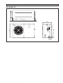
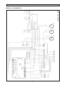
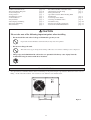
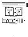
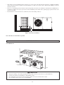
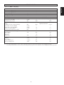
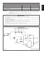
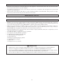
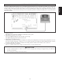
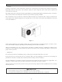
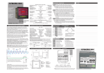
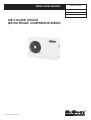
INSTALLATION MANUAL
IM-5ACC-0205SC
Group: Mini Chiller
Part Number: A08019024588
Date: February 2005
AIR COOLED CHILLER
(R410A SINGLE COMPRESSOR SERIES)
© 2005 McQuay International
OUTLINE AND DIMENSIONS
80,0
300,0
80,0
English
5AC 020/025 CR
10,0
1181,6
10,0
460,0
128,5
55,2
475,0
789,5
85,0
128,5
i
! Caution
Sharp edges and coil surfaces are potential locations which may cause
injury hazards. Avoid from being in contact with these places.
! Avertissement
Les bords coupants et les surfaces du refroidisseur tuulaire présentent
un risque de blessure. Mieux vaut éviter le contact avec ces endroits.
! Vorsicht
Scharfe Kanten und Wärmetauscherflächen stellen eine Gefahrenquelle dar.
Jeglicher Kontakt mit diesen Stellen ist zu vermeiden.
! Cautela
Per preservarsi da eventuali ferite, evitare di toccare gli spigoli affilali e la
superficie della serpentina.
! Cuidado
Los Bordes afilados y la superficie del serpentín pueden producir lesiones.
Evite tocarlos.
! Осторожно
Острые края и поверхности змеевиков являются
потенциальными местами нанесения травм. Остерегайтесь
контакта с этими местами.
NOTICE
This product is subjected to Waste of Electrical and Electronic Equipment Regulations (WEEE
Regulations). The waste product shall be separately collected by specific collection and treatment centre.
Please refer to local authorithy for these centres. This is only applicable to European Union countries.
Ce produit est soumis à la ré
é
é
é
ê
é
éé
é
est uniquement applicable aux pays de l'Union Européenne.
é
é
électriques et
é
ître ces centres. Ceci
Dieses Produkt unterliegt den Bestimmungen zur Entsorgung von elektrischen und elektronischen
Gerää
ä
ätes
üll bei Ihrer ö
ü
ö
äändiges Abfall-Amt. Dieser
Hinweis gilt nur fü
f rL
äischen Union.
Questo prodotto è soggetto alle disposizioni RAEE (Rifiuti di apparecchiature elettriche ed elettroniche).
à
à locali. Questa disposizione è valida solamente i paesi
dell’U.E.
ñ
éctrico y Electrónico en materia de
í
ífico
á
de colecció
solamente aplicable a los países de la Unión Europea.
Процесс утилизации данного продукта регулируется правилами по утилизации
отходов
и
(WEEE Regulations).
и
,
. Эти
правила
Европейского
.
ii
W_PUMP
AUX-H
BOILER
COM1
COM2
LIVE
iii
220-240/1pH/50Hz
TB1 L/L1 N/L2
ALM_OUT
ALM_IN
A_FREEZE
4WV1
OUT_FAN1
LP
1
FL
OFF
HEAT
COOL
4WV
H
T
R
AL AL
IN OUT
ENTERING WATER SENSOR
LEAVING WATER SENSOR
OUTDOOR AIR TEMP SENSOR
COMP DISCHARGE SENSOR (1)
DEFROST SENSOR (1)
O/F C/H 4WV PUMP HTR
HP
ON
2
WI WO OA CD1 CD2 DF1 DF2
4WV2
TB2 12V 12V 12V N1 N1 N1
12V
F02
F01
LP2
LP1
HP2
HP1
C02
C01
FLOW
PO
ALM
DE2
DE1
C/H
ON/OFF
OUT_FAN2
CN6
TB3
OF
IN
OF
OUT
95
98
COMP
96
E
COMP.
C S R
C O/L
1A
2A
PUMP
L NE
4B
5B
FUSE
10A
SWITCH
N
OF
L N C
S
C
COMP
CAP
OF
CAP
R
R
A
B
R1
8
7
R2
8
1 R 2
E
3 L 4
A
5 Y 6
English
PART NO : 50 13 4 066985
7
1 R 2
E
3 L 4
A
5 Y 6
ELECTRICAL WIRING DIAGRAM
MODEL : 5AC 020/025 CR
ISOLATOR DIAGRAM
AC TERMINAL BOX
TB1 L/L1 N/L2
E
ISOLATOR
FUSE
L1 N
Power supply 230V / 1Ph-N / 50Hz
5AC/AC020/025 CR
iv
English
INSTALLATION MANUAL
This manual provides the procedures of installation to ensure a safe and good standard of operation for the
chiller.
Special adjustments may be necessary to suit local requirements.
Before using the chiller, please read this instruction manual carefully and keep it for future reference.
AIR COOLED CHILLER
MODEL
HEAT PUMP
R410A
5AC 020 CR / M5AC 020 CR
5AC 025 CR / M5AC 025 CR
! WARNING
•
Installation and maintenance should be performed by qualified person who are familiar with local code and
regulation, and experienced with this type of appliance.
Part No.: A08019024588
IM-5ACC-0205SC
INDEX
- Outline And Dimensions
- Electrical Wiring Diagram
- Isolator Diagram
- Transportation
- Installation Location
- Unit Installation
- Physical Data
- Water Piping and Fitting
- Electrical And Wiring
- Electrical Data
page
page
page
page
page
page
page
page
page
page
i-ii
iii
iv
1
2
3
4
5
5
5
- Recommended Fuse And Cable Sizes
- Water Piping System Setup
- Refrigerant Circuit
- Special Precautions When Dealing With
R410A Unit
- Control Operation Guide
- Servicing And Maintenance
- Troubleshooting
- Fan Speed Controller (Optional)
- Isolator Switch Field Installation
page 6
page 7
page 7
page
page
page
page
page
page
7
8
9
10
11
11
! CAUTION
Please take note of the following important points when installing.
• Do not install the unit where leakage of flammable gas may occur.
If gas leaks and accumulates around the unit, it may cause fire ignition.
• Do not overcharge the unit.
This unit is factory pre-charged. Overcharge will cause over-current or damage to the compressor.
• Sharp edges and aluminium fin coil surface are potential which may cause injury hazards.
Avoid from being in contact with these locations.
TRANSPORTATION
•
Use spreader bars or forklift to lift the unit to avoid damage to the panels. Figure 1 provides the dimensions of the crate for
lifting. Avoid violent movements. Do not remove crate until it is at its final location.
640.0
Figure 1
1-1
MIN 500
500
500
AIR FLOW
1500
AIR FLOW
500
Figure 2: For single unit installation
500
1000
1000
500
AIR FLOW
AIR FLOW
AIR FLOW
AIR FLOW
1500
•
•
•
Installation work should be done by the authorized dealer or qualified contractor. Never install the unit yourself.
Make sure there is sufficient space for airflow around the unit. The discharged air should be directed outside using a duct
should the unit be installed in a plant room.
Vibration isolator should be provided to prevent vibration and noise from the unit.
When installing the unit on the ground, make sure the selected site is not subject to flooding.
There should be sufficient space allocated for ventilation, servicing and maintenance when installing the unit. Refer to the
following figures for proper location.
AIR FLOW
•
•
MIN 500
Figure 3: For multiple unit installation
1-2
English
INSTALLATION LOCATION
•
•
•
Unit subjects to floor installation must be placed on a concrete slab. The slab must have thickness of 100mm and 50mm
wider and longer than the footprint of the unit (Figure 4). Place the concrete slab a distant from building to prevent
vibration and noise.
In the case of heatpump operation with an outdoor temperature below 0°C, the unit must be installed at least 300mm above
ground level. This is necessary to prevent ice from accumulating on the frame and to permit proper operation in the event
of heavy snowfalls.
The unit must be leveled on both axes. (Tolerance is less than 2mm per meter.)
50
100
50
Figure 4: For floor installation
Note: All units are in mm unless specified.
UNIT INSTALLATION
5AC 020/025 CR
! CAUTION
•
•
•
•
Improper handling of unit during installation could result in leaks, electrical shock or unit malfunction.
Contact your dealer for reinstallation or dismantling of unit.
Do not introduce foreign objects such as fingers, sticks etc. into the air inlet and air outlet.
Do not climb or place objects on top of mini chiller.
1-3
PHYSICAL DATA
Model
5AC020CR
5AC025CR
4.98
6.15
Nominal cooling capacity
kW
Nominal heating capacity
kW
6.30
7.320
Operating Weight
kg
115.50
122.50
Refrigerant charge R410A
kg
1.20
Compressor
1.725
1 Rotary comp
Control system
LCD Electronic Control
Refrigerant - water heat exchanger
Water connections (BSP)
Maximum water pressure
inches
kPa
1
1000
Hydronic circuit
Pump
Available pressure (Cooling / Heating)
Water inlet connection (BSPT)
Water outlet connection (BSPT)
Drain tap coupling (BSPT)
Closed expansion tank water volume
kPa
inches
inches
inches
litre
87/68
1
1
1/2
2
163/93
1
1
1/2
2
mm
9.52
1
30
1.27
9.52
2
30
1.59
18
5
62.3
910
18
5
62.3
920
Refrigerant - air heat exchanger
Tube diameter
No. of rows
Tubes/row
Fin spacing
O/D Fan
Diameter
No. of blades
Air flow (high speed)
Fan speed (high speed)
Brazed Plate Heat Exchanger
1
1000
High Head Circulator
mm
inches
m3/min
r/min
Note: For cooling nominal values are based on 12°C / 7°C entering / leaving evaporator water temperature, 35°C air ambient temperature.
For heating nominal values are based on 40°C / 45°C entering / leaving evaporator water temperature, 7°C/6°C (DB/WB) air ambient temperature.
1-4
English
Table A-1 : R410A - Heatpump
WATER PIPING AND FITTING
•
•
•
•
•
•
•
•
•
All water pipe must be adequately insulated to prevent capacity losses and condensation.
Install a 40 to 60-mesh strainer to ensure good water quality.
Water pipes recommended are black steel pipe and copper pipe.
During installation, the piping of the unit should be clamped before rotating the installation pipe to reduce the moment
induce on the piping.
Users are recommended to install the pipes and accessories as shown in Figure 5.
An air vent must be installed at the highest position, while a drainage plug at the lowest position of the water circuit. After
the leak test (0.6MPa), open the air vent to release any air trapped in the water circuit.
Run the clean water through the water inlet and operate the pump to drain out the dirty water. Clean the strainer after
running the pump for 30 minutes.
Fill up the water circuit after connecting the pipes and equipment. Check water leakage at all connections and joints. Do
not start the unit when the system is leaking.
To optimize the capacity of the system, ensure that the system is free of air bubbles. The air trapped in the system would
make the system unbalanced.
5AC 020/025 CR
AIRVENT (INSTALL
HIGHEST POSITION)
PRESSURE GAUGE
GATE
VALVE
GATE
VALVE
GATE BALANCING
VALVE
VALVE
THERMOMETER
FAN COIL UNIT/AIR HANDLING UNIT
BALANCING
VALVE
THERMOMETER
FLEXIBLE
GATE VALVE
BYPASS VALVE
ENT PRESSURE TYPE)
P (DIFFER
STRAINER
GATE VALVE
GATE VALVE (LOWER
POSITION FOR DRAINAGE)
CHECK
VALVE
MAKE UP
VALVE
Figure 5
! CAUTION
•
•
Do not allow water to remain in the water pipes if the unit is not operating for a long period.
Water must be drained out if the unit is not running during winter. Failing to do so would cause the pipe to crack.
Do not drink the chilled water in the unit.
ELECTRICAL AND WIRING
•
•
•
Refer to the wiring diagram provided on the unit when making electrical wiring.
Do not ground any electrical equipment to the water piping.
Install an external isolator switch (if it is not provided) to prevent electrical shock.
ELECTRICAL DATA
Table B-1 : ( R410A - Heatpump )
Model
5AC020CR
5AC025CR
Power supply
V-ph-Hz
230 / 1 / 50
Voltage range
V
220 - 240
Nominal Power Input (Cooling/Heating)
Nominal Current Input (Cooling/Heating)
kW
2.55/2.59
2.76/2.79
A
11.9/12.1
12.7/12.9
Maximum Starting Current
A
67
68
Pump Power Input (Cooling/Heating)
W
185/193
195/209
Full Load Current (FLA)
A
14
15
1-5
RECOMMENDED FUSE AND CABLE SIZES
Cooling / Heat Pump
Model
5AC020CR
220 ~ 240V /1Ph /50Hz + N + !
27
38
10
10
3
3
1.5
1.5
A
mm2
mm2
English
Voltage Range **
Recommended Fuse *
Power Supply Cable Size *
Number of Conductor
Interconnection Cable Size *
5AC025CR
IMPORTANT : * The figures shown in the table are for information purpose only. They should be checked and selected to
comply with the local/national codes of regulations. This is also subjected to the type of installation and
conductors used.
** The appropriate voltage range should be checked with label data on the unit.
! CAUTION
•
•
•
•
•
•
•
All field wiring must be installed in accordance with the national wiring regulation.
All the terminals and connections must be tightened. Improper connection and fastenings could cause electric shock,
short circuit and fire.
Ensure that the rated voltage of the unit corresponds to that of the name plate before commencing wiring work
according to the wiring diagram.
The unit must be GROUNDED to prevent possible hazards due to insulation failure.
All electrical wiring must not touch the refrigerant piping, compressor, pump, fan motor or any moving parts of
the fan motors.
Do not operate the chiller with wet hands. It would result in electric shock.
Do not use fuse of different amperage than stated. Using wire etc. to replace a fuse could cause equipment damage
or fire.
5AC 020/025 CR
Water / Refrigerant Circuit Diagram
CHECK
VALVE
FILTER
DRIER
HEATING
CAP
TUBE
CHECK
VALVE
COOLING
CAP
TUBE
BPHE
WATER
OUT
CHARGE
COMPENSATOR
AUTO AIR VENT
SUCTION
ACCUMULATOR
COMPRESSOR
WATER
IN
P
EXPANSION
TANK
WATER PUMP
WATER STORAGE
TANK
Figure 6
PART NO : 70-03-4-080547
1-6
WATER PIPING SYSTEM SETUP
•
•
•
Fill up the water circuit after connecting all the pipes and equipment. Perform leak checks for all connections and joints.
Do not start the unit when the system is leaking.
To optimize the capacity of the system, ensure that the system is free of air bubbles. The air trapped in the system would
make the system unbalanced.
Ensure that the water tank is not full. This is to ensure optimal performance of the mini chiller. If the pressure is too high,
release the pressure from the auto pressure relief valve on the tank.
REFRIGERANT CIRCUIT
•
All chiller units are pre-charged with R410A refrigerant.
SPECIAL PRECAUTIONS WHEN DEALING WITH R410A UNIT
•
•
•
•
•
•
R410A is a near azeotrope refrigerant blend of hydro fluorocarbon (HFC) which is environmental friendly. It has Zero
Ozone Depletion Potential (ODP=0) and this conforms to Montreal Protocol regulations. It has no flame propagation and
a low toxic refrigerant (rated as A1 by ARI). R410A is a mixture of R32 (50%) and R125 (50%).
POE oil is used as lubricant for R410A compressor, which is different from the mineral oil used for R22 compressor.
During installation or servicing, extra precaution must be taken not to expose the R410A system too long to moist air.
Residual POE oil in the piping and components can absorb moisture from the air.
Refrigerant R410A is more easily affected by dust of moisture compared with R22, make sure to temporarily cover the
ends of the tubing prior to installation.
No additional charge of compressor oil only is permitted.
No refrigerant other than R410A is permitted.
Tools designed specifically for R410A only.
i) Manifold gauge and charging hose
ii) Gas leak detector
iii) Refrigerant cylinder/charging cylinder
iv) Vacuum pump c/w adaptor
v) Flare tools
vi) Refrigerant recovery machine
! CAUTION
•
•
•
R410A must be charged as liquid. Usually R410A cylinder is equipped with a dip-pipe for liquid withdrawal.
If there is no dip-pipe, the cylinder should be inverted so as to withdraw liquid R410A from the valve.
Do not top-up when servicing leak, as this will reduce the unit performance. Vacuum the unit thoroughly and then
charge the unit with fresh R410A according to the amount recommended in the specification.
Do not touch the compressor or refrigerant piping when the chiller is running. If necessary wear protective gloves.
1-7
The unit is equipped with a microprocessor controller board. The microprocessor controller is provided to give temperature
control for the system by accurately measuring and controlling the water entering and water leaving temperature. The temperature setting in the unit is preset in the factory. It is not recommended to change the setting unless necessary. A wired
controller handset is connected to the microprocessor board. Every parameter setting and reading can be observed from the
LCD of the handset.
1. Handset location
The handset is located in the terminal box behind the service panel.
2. LED Display (microprocessor board)
The keypad LED will light up when the unit is powered up.
The LCD will light up when the unit is turned on.
3. LCD display (controller handset)
During normal operations, the LCD can display the entering water temperature, the leaving water temperature, the entering water setpoint temperature, compressor on or off status and outdoor air temperature. When malfunctioning occurred,
the LCD would blink. The display would show the faulty parameter and the date and time of the occurrence.
4. Controller functioning specification
There is a 3 minute delay for the compressor and fan motor to restart (default setting).
! CAUTION
•
•
Use the controller handset to switch on / off the unit. Do not plug off the main power supply directly, it would cause
the unit to breakdown.
Do not change the settings of the safety devices.
1-8
English
CONTROL OPERATION GUIDE
SERVICING AND MAINTENANCE
•
Servicing
Servicing or maintenance of these units must be carried out by experienced personnel with specific training in refrigeration.
Repeatedly check the safety devices and continuous cycling of control components. These items must be analyzed and
corrected before being reset.
The simple design of the refrigeration circuit totally eliminates potential problems during normal unit operation. No maintenance work is needed on the refrigeration circuit as long as the unit is operating normally.
Ease of maintenance has been taken into consideration during the design stage such that the unit is easily accessible from the
service panels. The electrical components are especially easy to access since it is located in the terminal box in the front
service panel (Figure 7).
Figure 7
Under normal circumstances, these chillers required only a check and cleaning of air intake through the coil surface. These
can be done monthly or quarterly depending on the surrounding where the units are installed.
When the surrounding is very oily or dusty, then the coils must be regularly cleaned by a qualified air condition service
technician to ensure sufficient cooling capacity and efficient unit operation. The normal life span might be shortened if no
proper service is provided.
•
Maintenance
For consistent performance and durability, always conduct proper and regular maintenance to the unit.
For prolong period of operation time, the heat exchanger will become dirty impairing its effectiveness and reducing the
performance of the units. Consult your local dealer about the cleaning of the heat exchanger.
No major maintenance or servicing is needed for the internal water circuit in the unit except the water pump failure. It is
advisable to conduct regular check on the filter and change the water filter if it is dirty or choked.
Always check the water level in the system in order to protect the moving components in the hydraulic kit from over heating
and excessive wear.
! CAUTION
•
•
Do not attempt to do any service or maintenance when the unit is operating.
Do not spray any chemical agents or flammable agents to the unit. It could cause fire or explosion.
1-9
TROUBLESHOOTING
SYMPTOMS
POSSIBLE CAUSES
1. Compressor does
not start.
• No power supply.
• Fuses blown or automatic circuit breakdown open.
• Defective contactor or coil.
• Unit is stopped because safety device has
tripped.
• Loose wires.
REMEDIAL ACTION
• Check power supply.
• Look for short circuit or grounded wires in
motor windings. Replace fuses and reset
circuit breakers when the fault has been
corrected. Check tightness and soundness of
all electrical connections.
• Repair or replace.
• Determine the type of safety shut down and
correct the default before the unit is restarted.
• Check wire connections and tighten terminal
screws.
• Compressor faulty.
• Contact local dealer.
2. Fan does not work.
• No power supply.
• Fan motor faulty.
• Check power supply.
• Contact local dealer.
3. Unit does work,
but insufficient
cooling.
• Thermostat setting too high.
• Condenser coil dirty.
• Obstacle blocking air inlet or outlet of the
unit.
• Insufficient refrigerant in the system.
• Improper water flow rate.
• Water in the system is contaminated.
• Reset thermostat.
• Contact local dealer.
• Remove the obstacle.
• No water in the system.
• Low water level in the system.
• Check water supply.
• Check water supply.
4. Flow Switch Error
! CAUTION
•
Troubleshooting must be performed by qualified personnel.
1-10
• Contact local dealer.
• Contact local dealer.
• Contact local dealer.
English
When any malfunction is occurred, immediately switch off the power supply to the unit, and contact the local dealer, if
necessary. Some simple troubleshooting tips are given below :
FAN SPEED CONTROLLER (OPTIONAL)
Operation of the mini chillers without any fan speed control is limited to an ambient
temperature of 17°C. With the fan speed control, the units are able to operate down to -5°C.
The fan speed controller does not come as a standard item in the mini chiller units. It is fieldinstalled.
All mini chillers will have a 1/4" access valve provided for along the liquid line of the refrigerant circuit. This valve is for direct pressure connection to the fan speed controller.
To install the fan speed controller, screw in the female adaptor to the 1/4" access valve. Use
a pair of spanners to tighten properly (max. torque 15 Nm). See Fig. 8. Ensure there is no
leakage at the joint.
Wire the fan speed controller to the terminal blocks. See Fig. 9.
TO (PCB)
OUT_FAN1
OF IN
Figure 8
TO (A) OF
CAPACITOR
TB1
TB3
15 Nm
L/L1
N/L2
OF OUT
L1
Remove this wire
when doing wiring
for fan speed
controller
N
Power supply 230V / 1Ph-N / 50Hz
TB3
OF IN OF OUT
Wiring for fan
speed controller
(FSC)
FSC
5AC 020/025 CR
Figure 9
ISOLATOR SWITCH FIELD INSTALLATION
The isolator switch does not come as standard item with the units. It is advisable to have it field installed. The isolator switch
must be capable of making, carrying and breaking currents under normal circuit condition. It must be of AC23A duty and fully
compliant to IEC: 947-3.
For isolator switch selection, check the starting and running consumption specified in Table B. Be sure to connect a ground
wire from incoming power supply, either direct to the terminal box panel or use an auxiliary ground terminal in the isolator
switch. To install an isolator switch, wire it to the terminal block as shown in the two figures in page iv.
1-11
•
In the event that there is any conflict in the interpretation of this manual and any translation of the same in any language,
the English version of this manual shall prevail.
•
The manufacturer reserves the right to revise any of the specification and design contain herein at any time without prior
notification.
•
En cas de désaccord sur l’interprétation de ce manuel ou une de ses traductions, la version anglaise fera autorité.
•
Le fabriquant se réserve le droit de modifier à tout moment et sans préavis la conception et les caractéristiques techniques
des appareils présentés dans ce manuel.
•
Im Falle einer widersprüchlichen Auslegung der vorliegenden Anleitung bzw. einer ihrer Übersetzungen gilt die Ausführung
in Englisch.
•
Änderungen von Design und technischen Merkmalen der in dieser Anleitung beschriebenen Geräte bleiben dem Hersteller
jederzeit vorbehalten.
•
Nel caso ci fossero conflitti nell’interpretazione di questo manuale o delle sue stesse traduzioni in altre lingue, la versione
in lingua inglese prevale.
•
Il fabbricante mantiene il diritto di cambiare qualsiasi specificazione e disegno contenuti qui senza precedente notifica.
•
En caso de conflicto en la interpretación de este manual, y en su traducción a cualquier idioma, prevalecerá la versión
inglesa.
•
El fabricante se reserva el derecho a modificar cualquiera de las especificaciones y diseños contenidos en el presente
manual en cualquier momento y sin notificación previa.
•
В случае противоречия перевода данного руководства с другими переводами одного и того же текста,
английский вариант рассматривается как приоритетный.
•
Завод-изготовитель оставляет за собой право изменять характеристики и конструкцию в любое время
без предварительного уведомления.