1
Operating and Installation
Instructions
Ventilation System
DA 362-75
DA 362-110
To prevent accidents
and machine damage,
read these instructions
before
installation or use.
UV
M.-Nr. 06 191 500
Contents
IMPORTANT SAFETY INSTRUCTIONS
Functional description
Guide to the hood
Operation
Main power switch . . . . . . . . . . . . . . . . . . . . . . . . . . . . . . . . . . . . . . . . . . . . . . . . . 10
Joystick . . . . . . . . . . . . . . . . . . . . . . . . . . . . . . . . . . . . . . . . . . . . . . . . . . . . . . . . . 10
Turning on the fan . . . . . . . . . . . . . . . . . . . . . . . . . . . . . . . . . . . . . . . . . . . . . . . . . 11
Selecting the power level. . . . . . . . . . . . . . . . . . . . . . . . . . . . . . . . . . . . . . . . . . . . 11
Delayed Shut Down . . . . . . . . . . . . . . . . . . . . . . . . . . . . . . . . . . . . . . . . . . . . . . . . 12
Turning off the fan . . . . . . . . . . . . . . . . . . . . . . . . . . . . . . . . . . . . . . . . . . . . . . . . . 12
Overhead lighting . . . . . . . . . . . . . . . . . . . . . . . . . . . . . . . . . . . . . . . . . . . . . . . . . 12
Filter timers . . . . . . . . . . . . . . . . . . . . . . . . . . . . . . . . . . . . . . . . . . . . . . . . . . . . . . 13
Checking the filter timers . . . . . . . . . . . . . . . . . . . . . . . . . . . . . . . . . . . . . . . . . . . . 13
Reprogramming the timers . . . . . . . . . . . . . . . . . . . . . . . . . . . . . . . . . . . . . . . . . . 14
Cleaning and care
Cleaning the casing . . . . . . . . . . . . . . . . . . . . . . . . . . . . . . . . . . . . . . . . . . . . . . . . 16
Grease filters . . . . . . . . . . . . . . . . . . . . . . . . . . . . . . . . . . . . . . . . . . . . . . . . . . . . . 17
Active charcoal filters. . . . . . . . . . . . . . . . . . . . . . . . . . . . . . . . . . . . . . . . . . . . . . . 19
Changing the light bulb . . . . . . . . . . . . . . . . . . . . . . . . . . . . . . . . . . . . . . . . . . . . . 20
After Sales Service
Installation instructions
Caring for the environment
Electrical data
Appliance dimensions
Installation
Air extraction mode . . . . . . . . . . . . . . . . . . . . . . . . . . . . . . . . . . . . . . . . . . . . . . . . 30
Recirculation mode . . . . . . . . . . . . . . . . . . . . . . . . . . . . . . . . . . . . . . . . . . . . . . . . 31
Installing the joystick . . . . . . . . . . . . . . . . . . . . . . . . . . . . . . . . . . . . . . . . . . . . . . . 33
Joystick extension . . . . . . . . . . . . . . . . . . . . . . . . . . . . . . . . . . . . . . . . . . . . . . . . . 33
Electrical connection . . . . . . . . . . . . . . . . . . . . . . . . . . . . . . . . . . . . . . . . . . . . . . . 34
Air extraction
2
IMPORTANT SAFETY INSTRUCTIONS
Read these Operating Instructions carefully before installing or
using the Ventilation System.
This appliance is intended for
residential use only. Use the
appliance only for its intended
purpose. The manufacturer cannot
be held responsible for damages
caused by improper use of the
hood.
This appliance complies with current
safety requirements. Improper use of
the appliance can lead to personal
injury and material damage.
READ AND SAVE THESE
INSTRUCTIONS
CAUTION
For General Ventilating Use Only.
Do Not Use To Exhaust Hazardous
Or Explosive Materials And Vapors.
This appliance is designed to vent
cooking smoke and odors only.
Be certain your appliance is
properly installed and grounded by
a qualified technician.
To guarantee the electrical safety of this
appliance, continuity must exist
between the appliance and an effective
grounding system. It is imperative that
this basic safety requirement be met. If
there is any doubt, have the electrical
system of the house checked by a
qualified electrician. The manufacturer
can not be held responsible for
damages caused by the lack, or
inadequacy of, an effective grounding
system.
Before connecting the appliance to
the power supply make sure that
the voltage and frequency listed on the
data plate correspond with the
household electrical supply. This data
must correspond to prevent machine
damage. Consult a qualified electrician
if in doubt.
Installation work and repairs should
only be performed by a qualified
technician in accordance with all
applicable codes and standards.
Repairs and other work by unqualified
persons could be dangerous and the
manufacturer will not be held
responsible.
3
IMPORTANT SAFETY INSTRUCTIONS
This equipment is not designed for
maritime use or for use in mobile
installations such as caravans or
aircraft. However, under certain
conditions it may be possible for an
installation in these applications. Please
contact the nearest Miele dealer or the
Technical Service Department with
specific requirements.
Before servicing or cleaning the
unit, switch power off at the service
panel and lock the service
disconnecting means to prevent power
from being switched on accidentally.
When the service disconnecting means
can not be locked, securely fasten a
prominent warning device, such as a
tag, to the service panel.
Before discarding an old
appliance, unplug it from the
power supply and remove the power
cord and any doors to prevent hazards.
Use
Do not allow children to play with
or operate the appliance or its
controls. Supervise its use by the
elderly or infirm.
Be careful when preparing a
flambé beneath the hood.
Flames may be drawn up into the hood
by the suction or grease filters may
catch fire.
Never operate gas burners without
pots.
Do not leave cooking surfaces
unattended while in use.
Overheated food, oil and grease can
catch fire.
Do not use the hood without the
grease filters in place.
Clean the grease filters regularly.
Dirty filters are a fire hazard.
Do not use a steam cleaner to
clean the hood. Steam could
penetrate electrical components and
cause a short circuit.
Always turn on the hood when
using the cooktop to prevent
damage from condensation.
4
IMPORTANT SAFETY INSTRUCTIONS
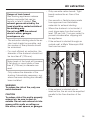
, WARNING - TO REDUCE
THE RISK OF A RANGE TOP
GREASE FIRE:
Never leave surface units
unattended at high settings.
Boilovers cause smoking and greasy
spillovers may ignite. Heat oils slowly
on low or medium settings.
Always turn the hood “ON” when
cooking at high heat or when
cooking flaming foods.
Clean ventilating fans frequently.
Grease should not be allowed to
accumulate on the fan or filter.
Use proper pan size. Always use
cookware appropriate for the size
of the surface element.
, WARNING
TO REDUCE THE RISK OF INJURY
TO PERSONS IN THE EVENT OF A
RANGE TOP GREASE FIRE,
OBSERVE THE FOLLOWING:
SMOTHER FLAMES with a close
fitting lid, cookie sheet, or metal
tray, then turn off the burner.
BE CAREFUL TO PREVENT BURNS.
If the flames do not go out immediately,
EVACUATE AND CALL THE FIRE
DEPARTMENT.
NEVER PICK UP A FLAMING
PAN - You may be burned.
DO NOT USE WATER, including
wet dishcloths or towels - a violent
steam explosion will result.
Use an extinguisher
ONLY if:
– You know you have a Class ABC
extinguisher, and you already know
how to operate it.
– The fire is small and contained in the
area where it started.
– The fire department is being called.
– You can fight the fire with your back
to an exit.
5
IMPORTANT SAFETY INSTRUCTIONS
Installation
, WARNING
To reduce the risk of fire only
use metal ductwork.
When installing the hood, follow the
recommended minimum safety
distances between a Miele cooktop and
the hood:
– 22" (55 cm) above electric cooktops,
– 26" (65 cm) above gas cooktops,
– 26" (65 cm) above an open grill.
If local building codes require a greater
safety distance, follow their
requirement.
For non-Miele cooking appliances
maintain the safety distances
recommended by the appliance
manufacturer in their instructions.
If there is more than one appliance
beneath the hood and they have
different minimum safety distances
always select the greater distance.
Be careful not to damage hidden
electrical wiring or plumbing when
cutting or drilling into the wall or ceiling.
Do not use an extension cord to
connect the appliance to electricity.
Extension cords do not guarantee the
required safety of the appliance, (e.g.
danger of overheating).
Do not install this hood over
cooktops burning solid fuel.
6
Any fittings, sealant, or materials
used to install the ductwork must
be made of approved non-flammable
materials.
Never connect an exhaust hood to
an active chimney, dryer vent, vent
flue, or room ventilating ductwork. Seek
professional advice before connecting
an exhaust hood vent to an existing,
inactive chimney or vent flue.
Ducted fans must always be
vented outdoors.
Make sure that the airflow in the
room is sufficient for combustion
and exhausting of all non-electric
heating appliances (water heaters, gas
cooktops, gas ovens, etc.), otherwise
backdrafts may occur. Follow the
heating manufacturer’s guidelines and
safety standards or those published by
the National Fire Protection Association
(NFPA), or the American Society for
Heating, Refrigeration and Air
Conditioning Engineers (ASHRAE).
If in doubt, consult an experienced
professional.
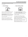
Functional description
The ventilation hood offers two modes
of operation:
. . . Air extraction:
. . . Recirculation mode:
The air is drawn in and cleaned by the
grease filters and directed outside.
Air is drawn through the grease filters
and active charcoal filters. The filtered
air is then recirculated back into the
kitchen through a vent at the top of the
hood’s chimney.
The hood comes equipped with a
non-return flap. This flap automatically
closes when the hood is turned off so
that no exchange of outside air and
room air can occur.
When the hood is turned on, the air
pressure of the exhaust fan automatically opens the flap blowing the
inside air and cooking odors outside.
The active charcoal filters may be
purchased from your Miele dealer or
Miele’s Technical Service Department.
Before using the hood in
recirculation mode, ensure that the
active charcoal filters are in place,
see "Cleaning and Care".
7
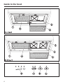
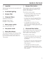
Guide to the hood
8
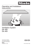
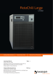
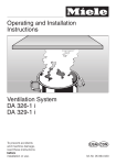
Guide to the hood
a Joystick
h Grease filter button
The fan and light can be operated with
the joystick.
The indicator above the grease filter
button lights when the grease filters
need to be cleaned.
b Overhead lighting
c Grease filter
d Charcoal filters
additional accessory
DA 362-75 two filters
DA 362-110 four filters
The button is also used:
– to reset the grease filter timer after
cleaning the grease filters (see
"Cleaning and Care").
– to show how long the grease filters
have been in use (see "Operation /
Filter timers").
only for the DA 362-110
– to change the number of hours
counted by the grease filter timer
(see "Operation / Reprogramming the
filter timers").
f Fan power scale
i Charcoal filter button
g Delay Shut Down
The indicator above the charcoal filter
button lights up when the charcoal
filters need to be replaced.
e Main power switch
This button activates the Delayed Shut
Down feature. The fan can be set to
turn off automatically after either 5 or
15 minutes.
The button is also used:
– to reset the charcoal filter timer after
changing the filters (see "Cleaning
and Care").
– to show how long the charcoal filters
have been in use (see "Operation /
Filter timers").
– to change the number of hours
counted by the charcoal filter timer
(see "Operation / Reprogramming the
filter timers").
9
Operation
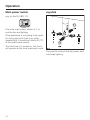
Main power switch
Joystick
only for the DA 362-110
Press the main power switch to "l" to
use the fan and lighting.
If the appliance is not going to be used
for a long period of time (e.g. while
vacationing) it should be turned off ("0")
at the main power switch.
The next time it is turned on, the hood
will operate at the level previously used.
The joystick controls the fan power and
overhead lighting.
10
Operation
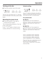
Turning on the fan
Intensive setting
^ Press the joystick once to the right.
The fan runs at power level “lI” and the
second indicator of the fan power scale
lights.
Selecting the power level
^ Press the joystick to the right, to
increase the fan speed.
The corresponding indicator of the fan
power scale lights.
Level "1" to "3" (green indicators) are
usually sufficient for normal cooking.
Level "4" (yellow indicator) should be
used for a short period when frying or
cooking food with a strong aroma.
Fan performance
DA 362-75:
The maximum air flow capacity is
425 cfm. Factors such as narrow duct
diameter and bends will affect this
value.
DA 362-110:
The maximum air flow capacity is
850 cfm. Factors such as narrow duct
diameter and bends will affect this
value.
Level 1 operates at 40% capacity
Level 2 operates at 60% capacity
Level 3 operates at 80% capacity
Level 4 operates at 100% capacity
There will also be a slight decrease in
airflow for hoods operated in
recirculation mode due to the active
charcoal filter.
11
Operation
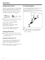
Delayed Shut Down
Overhead lighting
If odors or smoke remain in the kitchen
after cooking has been completed, the
Delayed Shut Down feature can be
selected to allow the hood to continue
running for either 5 or 15 minutes.
The overhead lighting can be turned on
and off independently of the fan.
^ Press the Delayed Shut Down button
while the fan is still running:
Press once = 5 minutes delay
(left indicator lights)
Press twice = 15 minutes delay
(right indicator lights)
To cancel the Delayed Shut Down
feature press the button again.
Turning off the fan
^ Hold the joystick to the left until the
fan shuts off and the fan power scale
indicators go out.
Automatic Safety Shut Off
The fan will turn off automatically 10
hours after the last movement of the
joystick. The lighting remains on.
^ Press the joystick once to the right to
turn the fan back on again.
12
^ To turn the light on or off, press the
joystick either once backwards or
once forwards.
Operation
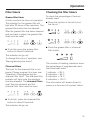
Filter timers
Checking the filter timers
Grease filter timer
To check the percentage of time set
already used:
A timer monitors the hours of operation.
The indicator for the grease filter will
light after 30 hours of fan operation. The
grease filters must then be cleaned.
^ Press the joystick to the left to turn
the fan on.
After the grease filter has been cleaned
and put back in place, the grease filter
timer must be reset.
^ To do this press the grease filter
button for about 3 seconds.
^ Press the grease filter or charcoal
filter button.
The indicator will go out.
To change the hours of operation, see
"Reprogramming the timers".
Charcoal filters
The timer for the charcoal filter is not
preset. Please program this timer, see
"Operation / Reprogramming the
charcoal filter timer". The charcoal filter
indicator will light once the selected
time has elapsed. The charcoal filters
must then be replaced and the
charcoal filter timer must be reset.
The number of flashing indicators show
the percentage of programmed hours
that have been used.
1 indicator = 25 %
2 indicators = 50 %
3 indicators = 75 %
4 indicators = 100 %
This information will remain stored in
memory in the event of a power failure.
^ To do this, press the charcoal filter
button for about 3 seconds.
The indicator will go out.
13
Operation
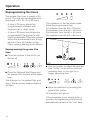
Reprogramming the timers
The grease filter timer is preset to 30
hours. This time can be lengthened or
shortened to 20, 30, 40 or 50 hours.
– A time of 20 hours should be
programmed in kitchens with
frequent pan or deep frying.
– A time of 20 hours should also be
programmed if the kitchen is only
used occasionally. Otherwise grease
which has accumulated over a long
period of time will harden on the
filters making cleaning more difficult.
The indicators of the fan power scale
show the programmed time:
1st indicator from the left = 20 hours
2nd indicator from the left = 30 hours
3rd indicator from the left = 40 hours
4th indicator from the left = 50 hours
Reprogramming the grease filter
timer
^ Press the joystick to the left to turn
the fan off.
^ Press the Delayed Shut Down and
the grease filter buttons at the same
time.
The indicator for the grease filter and
one of the fan power scale indicators
will flash.
^ Use the joystick to select the desired
time. Press it to the left for a shorter
operating time, to the right for a
longer operating time.
^ Store the selection by pressing the
grease filter button.
All indicators will go out.
If the procedure is not stored within 4
minutes of programming the hood will
automatically default to the “old” data.
14
Operation
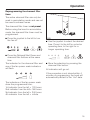
Reprogramming the charcoal filter
timer
The active charcoal filter can only be
used in recirculation mode and can not
be used to exhaust fumes.
The charcoal filter timer is not preset.
Before using the hood in recirculation
mode, the charcoal filter timer must be
programmed.
^ Press the joystick to the left to turn
the fan off.
^ Use the joystick to select the desired
time. Press it to the left for a shorter
operating time, to the right for a
longer operating time.
^ Press the Delayed Shut Down and
charcoal filter buttons at the same
time.
The indicator for the charcoal filter and
one of the fan power scale indicators
will flash.
^ Store the selection by pressing the
charcoal filter button.
All indicators will go out.
If the procedure is not stored within 4
minutes of programming, the hood will
automatically default to the “old” data.
The indicators of the fan power scale
show the programmed time:
1st indicator from the left = 120 hours
2nd indicator from the left= 180 hours
3rd indicator from the left = 240 hours
4th indicator from the left = infinite
15
Cleaning and care
Stainless steel
Before cleaning or servicing the
hood, disconnect it from the power
supply by either removing the fuse,
unplugging it from the outlet or
manually "tripping" the circuit
breaker.
Cleaning the casing
Warning: Never use abrasive
cleansers, scouring pads, steel wool
or caustic (oven) cleaners on the
hood. They will damage the surface.
^ All external surfces and controls can
be cleaned with warm water and
liquid dish soap applied with a soft
sponge.
^ Wipe dry using a soft cloth.
Do not use too much water when
cleaning the controls. Water could
penetrate into the electronics and
cause damage.
16
Stainless steel surfaces can be cleaned
using a non-abrasive stainless steel
cleaner.
To help prevent resoiling, a conditioner
for stainless steel can also be used.
Apply sparingly with even pressure.
Stainless steel colored controls
These controls may become discolored or damaged if not cleaned
regularly.
Do not use a stainless steel cleaner
on these controls.
Cleaning and care
Grease filters
Cleaning the grease filters
The reusable metal grease filters
remove solid particles from the vented
kitchen air (grease, dust, etc).
^ Clean the filters:
The grease filters should be cleaned
every 3-4 weeks or whenever the
grease filter indicator lights.
A dirty filter is a fire hazard.
– by hand: use a scrub brush in warm
water with a mild detergent.
– in a dishwasher: place the filters
vertically and diagonally in the lower
basket. If necessary adjust the upper
basket. Make sure that the spray arm
can rotate freely.
Depending on the detergent,
cleaning the grease filters in a
dishwasher may cause permanent
discoloration of the filter surface.
Performance of the filter will not be
affected by this discoloration.
^ After cleaning, leave the filters on a
towel to air dry.
^ While the filters are removed, clean
any dirt or grease from the filter
casing to prevent the risk of fire.
^ To remove the grease filters release
the latch. Holding carefully, lower and
remove the filter.
Be careful not to drop the filter onto
the cooktop while removing.
17
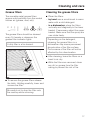
Cleaning and care
Inserting the grease filters
When putting the grease filters back
make sure that the locking clips are
visible facing down towards the
cooking surface.
If the filters are incorrectly installed,
insert a small screwdriver into the slit
along its edge to disengage it from the
casing.
^ After returning the grease filters,
press the grease filter button for 3
seconds to reset the timer. The
indicator light will go out.
^ If the grease filters are cleaned
before the grease filter timer has
reached its maximum, the grease
filter button should be pressed for 6
seconds to reset the counter to zero
18
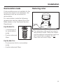
Cleaning and care
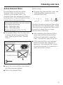
Active charcoal filters
Before using:
In recirculation mode four active
charcoal filters must be used in
addition to the grease filters. The
charcoal filters are designed to absorb
cooking odors. They are located in the
canopy above the grease filters.
^ Program the charcoal filter timer, see
"Operation/Reprogramming the
charcoal filter timer".
Active charcoal filters can be ordered
from Technical Service.
USA 1-800-999-1360
CDN 1-800-565-6435
Please quote part # 03 174 713
^ The grease filters must be removed
to acces the active charcoal filters
(see "Cleaning and Care / Grease
filters").
Replace the active charcoal filters when
the charcoal filter indicator lights. These
filters should be replaced at least every
6 months or when they no longer
absorb odors efficiently.
^ After replacing the charcoal filters,
press and hold the charcoal filter
button for 3 seconds to reset the
timer. The indicator light will go out.
^ If the charcoal filters are replaced
before the timer has reached its
maximum, the charcoal filter button
should be pressed for 6 seconds to
reset the counter to zero.
^ Insert the charcoal filters and fasten
with the enclosed screws.
^ Return the grease filters.
19
Cleaning and care
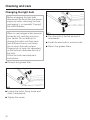
Changing the light bulb
Before changing the light bulb,
disconnect the hood from the power
supply by either removing the fuse,
unplugging it, or manually "tripping"
the circuit breaker.
When in use halogen bulbs become
extremely hot, and they can burn
your hands. Do not attempt to
change the bulbs until they have
had sufficient time to cool down.
Do not touch the bulb surface.
Fingerprints or body oils deposited
on the bulb will decrease the life of
the bulb.
Follow the bulb manufacturer’s
instructions.
^ Remove the grease filter.
^ Loosen the bulb’s fixing screw and
slide it downwards.
^ Tighten the screw.
20
^ Turn the bulb to the left and pull it
downwards.
^ Install the new bulb in reverse order.
^ Return the grease filters.
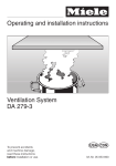
After Sales Service
In the event of a fault which you can not
correct yourself please contact the
Miele Technical Service Department
U
1-800-999-1360
[email protected]
V
1-800-565-6435
[email protected]
When contacting the Technical Service
Department, please quote the model
and serial number of your appliance.
These are shown on the data plate
which is visible when the grease filter is
removed.
21
22
Installation Instructions
Caring for the environment
Disposal of packing material
Disposal of an old appliance
The cardboard box and packing
materials protect the appliance during
shipping. They have been designed to
be biodegradable and recyclable.
Please recycle.
Old appliances may contain materials
that can be recycled. Please contact
your local recycling authority about the
possibility of recycling these materials.
To prevent suffocation of children,
ensure that any plastic wrappings,
bags etc. are disposed of safely and
kept out of their reach.
24
Before discarding an old hood,
unplug it from the outlet and cut off
its power cord to prevent hazards.
Electrical data
All electrical work should be
performed by a qualified electrician
in strict accordance with national
and local safety regulations.
Installation, repairs and other work
by unqualified persons could be
dangerous. The manufacturer can
not be held responsible for
unauthorized work.
Ensure that power to the appliance
is "OFF" while installation or repair
work is performed.
Verify that the voltage, load and circuit
rating information found on the data
plate (located behind the grease filter),
match the household electrical supply
before installing the hood.
If there is any question concerning the
electrical connection of this appliance
to your power supply, please consult a
licensed electrician or call Technical
Service.
USA 1-800-999-1360
CDN 1-800-565-6435
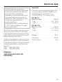
Important
The hood comes equippped with a 5 ft
(1.5 m) power cord with a NEMA 5-15
molded plug for connection to a
120 VAC, 60 Hz, 15 A power outlet.
DA 362-75:
Maximum load . . . . . . . . . . . . . . . 320 W
Fan. . . . . . . . . . . . . . . . . . . . 2 x 110 W
Light. . . . . . . . . . . . . . . . . . . . 2 x 50 W
DA 362-110:
Maximum load . . . . . . . . . . . . . . . 640 W
Fan. . . . . . . . . . . . . . . . . . . . 4 x 110 W
Light. . . . . . . . . . . . . . . . . . . . 4 x 50 W
Voltage . . . . . . . . . . . . . . . . . . . . . 120 V
Frequency . . . . . . . . . . . . . . . . . . 60 Hz
Circuit rating. . . . . . . . . . . . . . . . . . 15 A
WARNING:
THIS APPLIANCE MUST BE
GROUNDED
25
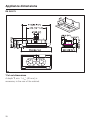
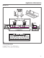
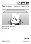
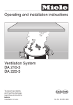
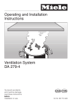
Appliance dimensions
DA 362-75
*Cut out dimensions
A depth T, min. 1 9/16" (40 mm), is
necessary in the rear of the cabinet.
26
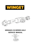
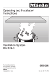
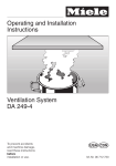
Appliance dimensions
DA 362-110
*Cut out dimensions
A depth T, min. 1 9/16" (40 mm), is
necessary in the rear of the cabinet.
27
Installation
Do not install this hood over any
appliance that burns solid fuel.
The minimum safety distance
allowed between the top of a Miele
cooking surface and the bottom of
the hood is:
– 22" (55 cm) above electric
cooktops
– 26" (65 cm) above gas cooktops
– 26" (65 cm) above an open grill
For non-Miele cooking appliances
maintain the safety distances
recommended by the cooktop
manufacturer in their installation and
operating instructions.
If there is more than one appliance
beneath the hood and they have
different minimum safety distances
always select the greater distance.
Observe local building codes.
See "Important Safety Instructions"
for further information.
26" (65 cm) is recommended for all
installations to allow for optimum work
space under the hood.
28
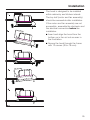
Installation
The hood is designed to be installed
within cabinetry and kitchen islands.
The top half (motor and fan assembly)
should be accessible after installation.
If the motor and fan assembly are not
accessible, assemble the ductwork and
the electical connection before the
installation.
^ Insert and align the hood from the
bottom up in the cut out as seen in
the illustration.
^ Secure the hood through the frame
with 12 screws (3.5 x 16 mm).
29
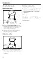
Installation
Air extraction mode
Non-return flaps
Exhaust connection
^ Connect the ductwork to the exhaust
connection using appropriate
measures for the type of ductwork
being installed (hose clamp, duct
tape, etc.).
Note:
A Y- adapter is supplied with the
DA 362-110. It may be used to feed the
exhaust from both connections to a
common duct.
^ Place the non-return flaps into the
exhaust connections at the top of the
motor assembly so that the flaps
open in the "up" direction.
^ Turn the non-return flaps slightly to
the left to lock them in place.
Reducing collar
^ If using 5" (125 mm) ducting, place
the reducing collars into the exhaust
connections and turn left to lock them
in place.
30
Installation
Recirculation mode
Reducing collar
If site conditions are not suitable for the
hood to be used for air extraction, the
appliance must be converted for
recirculation.
For recirculation mode the following
accessories can be ordered from your
Miele dealer or the Technical Service
Department:
For DA 362-75:
– 1 conversion kit
for recirculation
mode
– 2 active charcoal
filters
^ The reducing collar must be used in
recirculation mode. Place the collars
into the exhaust connections and turn
left to lock them in place. Do not
insert the non-return flaps.
For Da 362-110:
– 2 conversion kits for recirculation
mode
– 4 active charcoal filters
31
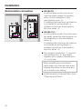
Installation
Recirculation connection
^ DA 362-75:
In recirculation mode, one cut out
must be made, where the ducting
ends, for the installation of the
recirculation vents, b.
If installing the hood over an island or
in a cabinet at ceiling height, a
suitable cut-out has to be made in
the front panel, d.
^ DA 362-110:
In recirculation mode, 2 cut outs must
be made, where the ducting ends, for
the installation of the recirculation
vents, b.
If installing the hood over an island or
in a cabinet at ceiling height, a
suitable cut-out has to be made in
the front panel, d.
^ The exhaust connection, a, and the
recirculation vent, b, are joined
together with a pipe or flexible duct,
c, cut to size.
When installing the recirculation
vents make sure that the slats point
towards the center of the room and
not to a wall or the ceiling.
^ Install the active charcoal filters (see
"Cleaning and Care").
32
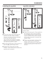
Installation
Installing the joystick
Joystick extension
The joystick can be extended for an
easier reach.
^ Insert the lower half of the desired
joystick into the socket, loosely
secure it in place with the included
screw and spring washer.
The screws have different lengths.
Make sure the respective screw for
the desired joystick is used.
^ Turn the printed part of the joystick so
that the m-symbol faces front.
^ Attach the lower part of the joystick to
the extension with a spring washer.
Turn the m-symbol to the front and
screw in place with an allen wrench
while using a wrench to counter the
joystick base.
^ Place a spring washer between the
joystick base and the extension.
Tighten the extension by hand while
countering the joystick base with a
wrench.
^ Tighten the screw with an allen
wrench. At the same time counter the
joystick with a wrench.
33
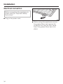
Installation
Electrical connection
Before connecting the appliance to
power read the "Important Safety
Instructions".
^ Plug in the power cord.
^ Before using the appliance remove
the grease filters and remove the
protective foil from the filter frame.
Insert the grease filters back into
place.
34
Air extraction
Danger of toxic fumes!
Gas cooking appliances release
carbon monoxide that can be
harmful or fatal if inhaled. The
exhaust gases extracted by the
hood should be vented outside of
the building only.
Do not terminate the exhaust
ducts in attics, garages,
crawlspaces, etc.
– The extraction ducting should be as
short and straight as possible, and
the number of sharp bends should
be minimized.
– Only use wide radius bends. Tight
bends reduce the air flow of the
hood.
– Use smooth or flexible pipes made
from approved non-flammable
materials for exhaust ducting.
– Where the ductwork is horizontal, it
must slope away from the hood at
least 1/8" per foot (1 cm per meter) to
prevent condensation dripping into
the appliance.
– If the exhaust is ducted through an
outside wall, a Miele Telescopic Wall
Vent can be used.
– For most efficient air extraction, the
diameter of the ductwork should not
be less than 5" (125 mm).
Noise levels of the hood will increase
if flat ducts or round ducts of less
than 5" (125 mm) in diameter are
used.
Only reduce the diameter of the
ducting if absolutely necessary, e.g.
where narrower ducting has already
been installed.
WARNING
To reduce the risk of fire, only use
metal ductwork.
CAUTION
To reduce risk of fire and to properly
exhaust air, be sure to duct air
outside. Do not vent exhaust air into
spaces within walls or ceilings or
into attics, crawl spaces, or garages.
– If the exhaust is ducted into an
inactive flue, the air must be expelled
parallel to the flow direction of the
flue.
35
Air extraction
Never connect an exhaust hood to
an active chimney, dryer vent, vent
flue, or room venting ductwork. Seek
professional advice before
connecting an exhaust hood vent to
an existing, inactive chimney or vent
flue.
Important:
If the ductwork runs through rooms,
ceilings, garages, etc. where temperature variations exist, it may need to be
insulated to reduce condensation. In
some cases, a condensate trap may
also be required to collect and
evaporate any condensate which may
occur.
When installing a condensate trap,
ensure that it is positioned vertically
and if possible directly above the
exhaust outlet.
36
37
38
39
Alteration rights reserved / 2204
This paper was bleached without the use of chlorine.
M.-Nr. 06 191 500 / 01