1
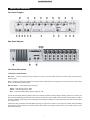
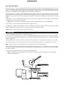
English . . . . . . . . . . . . . . . . . . . . . . . . . . . . . . . . . . . . . . . . . . . . . . . . . . . . . . . . . . . . . . . . . . . . . . . . .2
Introduction . . . . . . . . . . . . . . . . . . . . . . . . . . . . . . . . . . . . . . . . . . . . . . . . . . . . . . . . . . . . . . . . . . . . . . . . . . . . . . . . . . . . . . . . . . . . . . . . . . . . . . . . .2
What’s in the Box . . . . . . . . . . . . . . . . . . . . . . . . . . . . . . . . . . . . . . . . . . . . . . . . . . . . . . . . . . . . . . . . . . . . . . . . . . . . . . . . . . . . . . . . . . . . . . . . . . . .2
About Octane . . . . . . . . . . . . . . . . . . . . . . . . . . . . . . . . . . . . . . . . . . . . . . . . . . . . . . . . . . . . . . . . . . . . . . . . . . . . . . . . . . . . . . . . . . . . . . . . . . . . . . .2
Features . . . . . . . . . . . . . . . . . . . . . . . . . . . . . . . . . . . . . . . . . . . . . . . . . . . . . . . . . . . . . . . . . . . . . . . . . . . . . . . . . . . . . . . . . . . . . . . . . . . . . . . . . . . .2
Controls and Connectors . . . . . . . . . . . . . . . . . . . . . . . . . . . . . . . . . . . . . . . . . . . . . . . . . . . . . . . . . . . . . . . . . . . . . . . . . . . . . . . . . . . . . . . . . . . . . .3
Front Panel Descriptions . . . . . . . . . . . . . . . . . . . . . . . . . . . . . . . . . . . . . . . . . . . . . . . . . . . . . . . . . . . . . . . . . . . . . . . . . . . . . . . . . . . . . . . . . .3
Rear Panel Descriptions . . . . . . . . . . . . . . . . . . . . . . . . . . . . . . . . . . . . . . . . . . . . . . . . . . . . . . . . . . . . . . . . . . . . . . . . . . . . . . . . . . . . . . . . . .5
Connections . . . . . . . . . . . . . . . . . . . . . . . . . . . . . . . . . . . . . . . . . . . . . . . . . . . . . . . . . . . . . . . . . . . . . . . . . . . . . . . . . . . . . . . . . . . . . . . . . . . . . . . . .5
Using the Octane . . . . . . . . . . . . . . . . . . . . . . . . . . . . . . . . . . . . . . . . . . . . . . . . . . . . . . . . . . . . . . . . . . . . . . . . . . . . . . . . . . . . . . . . . . . . . . . . . . . .6
Troubleshooting . . . . . . . . . . . . . . . . . . . . . . . . . . . . . . . . . . . . . . . . . . . . . . . . . . . . . . . . . . . . . . . . . . . . . . . . . . . . . . . . . . . . . . . . . . . . . . . . . . . . . .8
Specifications . . . . . . . . . . . . . . . . . . . . . . . . . . . . . . . . . . . . . . . . . . . . . . . . . . . . . . . . . . . . . . . . . . . . . . . . . . . . . . . . . . . . . . . . . . . . . . . . . . . . . . . .9
Warranty . . . . . . . . . . . . . . . . . . . . . . . . . . . . . . . . . . . . . . . . . . . . . . . . . . . . . . . . . . . . . . . . . . . . . . . . . . . . . . . . . . . . . . . . . . . . . . . . . . . . . . . . . . .10
Contact M-Audio . . . . . . . . . . . . . . . . . . . . . . . . . . . . . . . . . . . . . . . . . . . . . . . . . . . . . . . . . . . . . . . . . . . . . . . . . . . . . . . . . . . . . . . . . . . . . . . . . . . .10
Français - . . . . . . . . . . . . . . . . . . . . . . . . . . . . . . . . . . . . . . . . . . . . . . . . . . . . . . . . . . . . . . . . . . . . . .11
Introduction . . . . . . . . . . . . . . . . . . . . . . . . . . . . . . . . . . . . . . . . . . . . . . . . . . . . . . . . . . . . . . . . . . . . . . . . . . . . . . . . . . . . . . . . . . . . . . . . . . . . . . . . .11
Contenu de la boîte . . . . . . . . . . . . . . . . . . . . . . . . . . . . . . . . . . . . . . . . . . . . . . . . . . . . . . . . . . . . . . . . . . . . . . . . . . . . . . . . . . . . . . . . . . . . . . . . . .11
A propos d’Octane . . . . . . . . . . . . . . . . . . . . . . . . . . . . . . . . . . . . . . . . . . . . . . . . . . . . . . . . . . . . . . . . . . . . . . . . . . . . . . . . . . . . . . . . . . . . . . . . . . .11
Caractéristiques . . . . . . . . . . . . . . . . . . . . . . . . . . . . . . . . . . . . . . . . . . . . . . . . . . . . . . . . . . . . . . . . . . . . . . . . . . . . . . . . . . . . . . . . . . . . . . . . . . . . .11
Contrôles et connecteurs . . . . . . . . . . . . . . . . . . . . . . . . . . . . . . . . . . . . . . . . . . . . . . . . . . . . . . . . . . . . . . . . . . . . . . . . . . . . . . . . . . . . . . . . . . . . .12
Légende face avant . . . . . . . . . . . . . . . . . . . . . . . . . . . . . . . . . . . . . . . . . . . . . . . . . . . . . . . . . . . . . . . . . . . . . . . . . . . . . . . . . . . . . . . . . . . . .12
Légende face arrière . . . . . . . . . . . . . . . . . . . . . . . . . . . . . . . . . . . . . . . . . . . . . . . . . . . . . . . . . . . . . . . . . . . . . . . . . . . . . . . . . . . . . . . . . . . .14
Connexions . . . . . . . . . . . . . . . . . . . . . . . . . . . . . . . . . . . . . . . . . . . . . . . . . . . . . . . . . . . . . . . . . . . . . . . . . . . . . . . . . . . . . . . . . . . . . . . . . . . . . . . .14
Utilisation d’Octane . . . . . . . . . . . . . . . . . . . . . . . . . . . . . . . . . . . . . . . . . . . . . . . . . . . . . . . . . . . . . . . . . . . . . . . . . . . . . . . . . . . . . . . . . . . . . . . . . .15
Dépannage . . . . . . . . . . . . . . . . . . . . . . . . . . . . . . . . . . . . . . . . . . . . . . . . . . . . . . . . . . . . . . . . . . . . . . . . . . . . . . . . . . . . . . . . . . . . . . . . . . . . . . . .17
Spécifications . . . . . . . . . . . . . . . . . . . . . . . . . . . . . . . . . . . . . . . . . . . . . . . . . . . . . . . . . . . . . . . . . . . . . . . . . . . . . . . . . . . . . . . . . . . . . . . . . . . . . . .18
Nous contacter . . . . . . . . . . . . . . . . . . . . . . . . . . . . . . . . . . . . . . . . . . . . . . . . . . . . . . . . . . . . . . . . . . . . . . . . . . . . . . . . . . . . . . . . . . . . . . . . . . . . .19
Garantie . . . . . . . . . . . . . . . . . . . . . . . . . . . . . . . . . . . . . . . . . . . . . . . . . . . . . . . . . . . . . . . . . . . . . . . . . . . . . . . . . . . . . . . . . . . . . . . . . . . . . . . . . . .19
Deutsch . . . . . . . . . . . . . . . . . . . . . . . . . . . . . . . . . . . . . . . . . . . . . . . . . . . . . . . . . . . . . . . . . . . . . . .20
Einführung . . . . . . . . . . . . . . . . . . . . . . . . . . . . . . . . . . . . . . . . . . . . . . . . . . . . . . . . . . . . . . . . . . . . . . . . . . . . . . . . . . . . . . . . . . . . . . . . . . . . . . . . .20
Lieferumfang . . . . . . . . . . . . . . . . . . . . . . . . . . . . . . . . . . . . . . . . . . . . . . . . . . . . . . . . . . . . . . . . . . . . . . . . . . . . . . . . . . . . . . . . . . . . . . . . . . . . . . .20
Produktmerkmale . . . . . . . . . . . . . . . . . . . . . . . . . . . . . . . . . . . . . . . . . . . . . . . . . . . . . . . . . . . . . . . . . . . . . . . . . . . . . . . . . . . . . . . . . . . . . . . . . . .20
Regler und Anschlüsse . . . . . . . . . . . . . . . . . . . . . . . . . . . . . . . . . . . . . . . . . . . . . . . . . . . . . . . . . . . . . . . . . . . . . . . . . . . . . . . . . . . . . . . . . . . . . . .21
Bedienelemente der Frontseite . . . . . . . . . . . . . . . . . . . . . . . . . . . . . . . . . . . . . . . . . . . . . . . . . . . . . . . . . . . . . . . . . . . . . . . . . . . . . . . . . . .21
Bedienelemente der Rückseite . . . . . . . . . . . . . . . . . . . . . . . . . . . . . . . . . . . . . . . . . . . . . . . . . . . . . . . . . . . . . . . . . . . . . . . . . . . . . . . . . . . .23
Anschlüsse . . . . . . . . . . . . . . . . . . . . . . . . . . . . . . . . . . . . . . . . . . . . . . . . . . . . . . . . . . . . . . . . . . . . . . . . . . . . . . . . . . . . . . . . . . . . . . . . . . . . . . . .23
Benutzung . . . . . . . . . . . . . . . . . . . . . . . . . . . . . . . . . . . . . . . . . . . . . . . . . . . . . . . . . . . . . . . . . . . . . . . . . . . . . . . . . . . . . . . . . . . . . . . . . . . . . . . . .24
Technische Daten . . . . . . . . . . . . . . . . . . . . . . . . . . . . . . . . . . . . . . . . . . . . . . . . . . . . . . . . . . . . . . . . . . . . . . . . . . . . . . . . . . . . . . . . . . . . . . . . . . .27
Kontaktieren Sie uns! . . . . . . . . . . . . . . . . . . . . . . . . . . . . . . . . . . . . . . . . . . . . . . . . . . . . . . . . . . . . . . . . . . . . . . . . . . . . . . . . . . . . . . . . . . . . . . . .28
Garantie . . . . . . . . . . . . . . . . . . . . . . . . . . . . . . . . . . . . . . . . . . . . . . . . . . . . . . . . . . . . . . . . . . . . . . . . . . . . . . . . . . . . . . . . . . . . . . . . . . . . . . . . . . .28
Español . . . . . . . . . . . . . . . . . . . . . . . . . . . . . . . . . . . . . . . . . . . . . . . . . . . . . . . . . . . . . . . . . . . . . . .29
Introducción . . . . . . . . . . . . . . . . . . . . . . . . . . . . . . . . . . . . . . . . . . . . . . . . . . . . . . . . . . . . . . . . . . . . . . . . . . . . . . . . . . . . . . . . . . . . . . . . . . . . . . . .29
¿Qué hay dentro de la caja? . . . . . . . . . . . . . . . . . . . . . . . . . . . . . . . . . . . . . . . . . . . . . . . . . . . . . . . . . . . . . . . . . . . . . . . . . . . . . . . . . . . . . . . . . .29
Acerca de Octane . . . . . . . . . . . . . . . . . . . . . . . . . . . . . . . . . . . . . . . . . . . . . . . . . . . . . . . . . . . . . . . . . . . . . . . . . . . . . . . . . . . . . . . . . . . . . . . . . . .29
Características . . . . . . . . . . . . . . . . . . . . . . . . . . . . . . . . . . . . . . . . . . . . . . . . . . . . . . . . . . . . . . . . . . . . . . . . . . . . . . . . . . . . . . . . . . . . . . . . . . . . . .29
Controles y conectores . . . . . . . . . . . . . . . . . . . . . . . . . . . . . . . . . . . . . . . . . . . . . . . . . . . . . . . . . . . . . . . . . . . . . . . . . . . . . . . . . . . . . . . . . . . . . . .30
Descripción del panel frontal . . . . . . . . . . . . . . . . . . . . . . . . . . . . . . . . . . . . . . . . . . . . . . . . . . . . . . . . . . . . . . . . . . . . . . . . . . . . . . . . . . . . .30
Descripción del panel trasero . . . . . . . . . . . . . . . . . . . . . . . . . . . . . . . . . . . . . . . . . . . . . . . . . . . . . . . . . . . . . . . . . . . . . . . . . . . . . . . . . . . .32
Conexiones . . . . . . . . . . . . . . . . . . . . . . . . . . . . . . . . . . . . . . . . . . . . . . . . . . . . . . . . . . . . . . . . . . . . . . . . . . . . . . . . . . . . . . . . . . . . . . . . . . . . . . . .32
Uso de Octane . . . . . . . . . . . . . . . . . . . . . . . . . . . . . . . . . . . . . . . . . . . . . . . . . . . . . . . . . . . . . . . . . . . . . . . . . . . . . . . . . . . . . . . . . . . . . . . . . . . . .33
Resolución de problemas . . . . . . . . . . . . . . . . . . . . . . . . . . . . . . . . . . . . . . . . . . . . . . . . . . . . . . . . . . . . . . . . . . . . . . . . . . . . . . . . . . . . . . . . . . . .35
Especificaciones . . . . . . . . . . . . . . . . . . . . . . . . . . . . . . . . . . . . . . . . . . . . . . . . . . . . . . . . . . . . . . . . . . . . . . . . . . . . . . . . . . . . . . . . . . . . . . . . . . . .36
Contactos . . . . . . . . . . . . . . . . . . . . . . . . . . . . . . . . . . . . . . . . . . . . . . . . . . . . . . . . . . . . . . . . . . . . . . . . . . . . . . . . . . . . . . . . . . . . . . . . . . . . . . . . . .37
Garantia . . . . . . . . . . . . . . . . . . . . . . . . . . . . . . . . . . . . . . . . . . . . . . . . . . . . . . . . . . . . . . . . . . . . . . . . . . . . . . . . . . . . . . . . . . . . . . . . . . . . . . . . . . .37
Italiano . . . . . . . . . . . . . . . . . . . . . . . . . . . . . . . . . . . . . . . . . . . . . . . . . . . . . . . . . . . . . . . . . . . . . . .38
Introduzione . . . . . . . . . . . . . . . . . . . . . . . . . . . . . . . . . . . . . . . . . . . . . . . . . . . . . . . . . . . . . . . . . . . . . . . . . . . . . . . . . . . . . . . . . . . . . . . . . . . . . . .38
Contenuto della confezione . . . . . . . . . . . . . . . . . . . . . . . . . . . . . . . . . . . . . . . . . . . . . . . . . . . . . . . . . . . . . . . . . . . . . . . . . . . . . . . . . . . . . . . . . . .38
Informazioni su Octane . . . . . . . . . . . . . . . . . . . . . . . . . . . . . . . . . . . . . . . . . . . . . . . . . . . . . . . . . . . . . . . . . . . . . . . . . . . . . . . . . . . . . . . . . . . . . .38
Caratteristiche . . . . . . . . . . . . . . . . . . . . . . . . . . . . . . . . . . . . . . . . . . . . . . . . . . . . . . . . . . . . . . . . . . . . . . . . . . . . . . . . . . . . . . . . . . . . . . . . . . . . . .38
Controlli e connettori . . . . . . . . . . . . . . . . . . . . . . . . . . . . . . . . . . . . . . . . . . . . . . . . . . . . . . . . . . . . . . . . . . . . . . . . . . . . . . . . . . . . . . . . . . . . . . . .39
Descrizioni pannello frontale . . . . . . . . . . . . . . . . . . . . . . . . . . . . . . . . . . . . . . . . . . . . . . . . . . . . . . . . . . . . . . . . . . . . . . . . . . . . . . . . . . . . .39
Descrizioni del pannello posteriore . . . . . . . . . . . . . . . . . . . . . . . . . . . . . . . . . . . . . . . . . . . . . . . . . . . . . . . . . . . . . . . . . . . . . . . . . . . . . . . .41
Connessioni . . . . . . . . . . . . . . . . . . . . . . . . . . . . . . . . . . . . . . . . . . . . . . . . . . . . . . . . . . . . . . . . . . . . . . . . . . . . . . . . . . . . . . . . . . . . . . . . . . . . . . . .41
Uso di Octane . . . . . . . . . . . . . . . . . . . . . . . . . . . . . . . . . . . . . . . . . . . . . . . . . . . . . . . . . . . . . . . . . . . . . . . . . . . . . . . . . . . . . . . . . . . . . . . . . . . . . .42
Risoluzione dei problemi . . . . . . . . . . . . . . . . . . . . . . . . . . . . . . . . . . . . . . . . . . . . . . . . . . . . . . . . . . . . . . . . . . . . . . . . . . . . . . . . . . . . . . . . . . . . .44
Specifiche Tecniche . . . . . . . . . . . . . . . . . . . . . . . . . . . . . . . . . . . . . . . . . . . . . . . . . . . . . . . . . . . . . . . . . . . . . . . . . . . . . . . . . . . . . . . . . . . . . . . . . .45
Contatti . . . . . . . . . . . . . . . . . . . . . . . . . . . . . . . . . . . . . . . . . . . . . . . . . . . . . . . . . . . . . . . . . . . . . . . . . . . . . . . . . . . . . . . . . . . . . . . . . . . . . . . . . . . .46
Garanzia . . . . . . . . . . . . . . . . . . . . . . . . . . . . . . . . . . . . . . . . . . . . . . . . . . . . . . . . . . . . . . . . . . . . . . . . . . . . . . . . . . . . . . . . . . . . . . . . . . . . . . . . . .46
Kanji . . . . . . . . . . . . . . . . . . . . . . . . . . . . . . . . . . . . . . . . . . . . . . . . . . . . . . . . . . . . . . . . . . . . . . . . . .47
Signal Flow Diagram • Schéma fonctionnel • Signalflussdiagramm • Diagrama de Flujo de Señal • Diagramma di flusso del segnale . . . .58
English
Introduction
Thank you for choosing the M-Audio Octane Microphone/Instrument Preamplifier. Octane offers you eight independent channels of studioquality high-gain, ultra-low noise mic preamps in a rugged, compact 2RU design. With eight inputs on balanced XLR connectors and eight
channels of ADAT optical output, Octane has been designed to be the ideal analog front end for your digital recording environment.
Octane is packed with a host of professional features normally found only in higher-priced, exotic microphone preamps – features like
independent instrument preamps on channels 1 and 2, Mid-Side matrix encoding on channels 7 and 8, switchable +48V phantom
power, and word clock I/O on BNC connectors. With up to 70dB of gain and 129dBm EIA noise performance, Octane is the perfect highperformance, cost-effective, multi-channel solution for the personal, project or professional studio.
What’s in the Box
Your Octane box contains the following items:
< Octane Microphone/Instrument Preamp
< 18VAC 3500mA Power Supply
< Users’ Manual
About Octane
Octane is a multi-channel microphone preamp, offering eight channels of low-noise, high-gain, professional quality preamplification in a twospace rack mount chassis.
Each channel has its own input level control, 20dB pad, and three-color LED level meter, with rear panel inputs on balanced XLR
connectors. Octane also offers eight independent analog Preamp Outputs on rear panel balanced/unbalanced TRS connectors, along
with 8 channels of A/D Line Inputs. These inputs are half-normalled (plugging a connector into the A/D Line Input will interrupt the signal
from the XLR input to the lightpipe output, but plugging a connector into the Line Output will not), and can be used as insert returns, or
to allow Octane to function as a standalone A/D converter.
Octane gives you front-panel high impedance instrument-level inputs on channels 1 and 2, using independent preamps and level
control for superior performance and better Signal-to-Noise ratio. Channels 7 and 8 offer M-S Matrix Encoding circuitry for Mid-Side
stereo recording. Each of Octane’s even-numbered channels (channels 2, 4, 6 and 8) offers a Phase Reverse switch for easy stereo
pairing, and +48V phantom power is switchable in two groups of four channels.
Features
<
<
<
<
<
<
<
<
<
<
<
<
Eight channels of high-quality, low-noise microphone preamps
Eight balanced XLR inputs
Separate mic level, pad and three segment LED meters on each channel
Switchable +48V phantom power
Two front-panel unbalanced high impedance instrument inputs with independent level controls
Mid-Side matrix encoding on channels 7 and 8
Eight balanced/unbalanced analog preamp outputs on TRS connectors
Eight balanced/unbalanced channel A/D line inputs on TRS connectors serve as inserts or standalone A/D converters
Phase reverse switch on even-numbered channels, low-cut filter on channel 1
ADAT lightpipe digital output
Front panel sample rate/external clock selector
Word clock I/O with low jitter Phase Locked Loop
2
Controls and Connectors
Front Panel Diagram
Rear Panel Diagram
Front Panel Descriptions
1. Channel 1 Level Controls –
Mic Level – Controls the input level of the channel’s mic preamp. Turn fully counter-clockwise for minimum gain, fully clockwise for
maximum gain.
Pad – Pressing and locking this switch to the IN position inserts a 20dB pad into the signal path. Use the pad when your input level is
too hot, as indicated by the Red Clip LED.
LED Level Meter – Three segment input level meter:
Green – Indicates input level of -20dB
Yellow – Indicates input level of -10dB
Red – Input level of 0dB indicates clipping. Triggers at -3dB.
A word about metering: Different hardware devices and software applications employ different metering schemes. For example, the
ADAT and some DAW programs will show level on their input meters at as low as -40dB, whereas Octane’s meters register at -20dB. It
is entirely possible that your DAW or other recording device will display a reading at very low audio levels, even when Octane’s meters
do not show a level.
In digital recording, particularly with 24-bit digital technology, it is important to achieve as hot a signal as possible without exceeding
0dB. The higher an input level you record with, the better the resolution of your digital recording. Do not go over 0dB, however, or your
signal will be distorted.
3
2. Channel 2 Level Controls – Identical to Channel 1 Level Controls, these control the settings for channel 2. Refer to Channel 1
description for more details.
3. Channel 3 Level Controls – Identical to Channel 1 Level Controls, these control the settings for channel 3. Refer to Channel 1
description for more details.
4. Channel 4 Level Controls – Identical to Channel 1 Level Controls, these control the settings for channel 4. Refer to Channel 1
description for more details.
5. Channel 5 Level Controls – Identical to Channel 1 Level Controls, these control the settings for channel 5. Refer to Channel 1
description for more details.
6. Channel 6 Level Controls – Identical to Channel 1 Level Controls, these control the settings for channel 6. Refer to Channel 1
description for more details.
7. Channel 7 Level Controls – Identical to Channel 1 Level Controls, these control the settings for channel 7. Refer to Channel 1
description for more details.
8. Channel 8 Level Controls – Identical to Channel 1 Level Controls, these control the settings for channel 8. Refer to Channel 1
description for more details.
9. Phantom Power Switches and LEDs – Pressing and locking the Phan 1-4 switch to the IN position activates +48V phantom power
to rear-panel XLR Inputs 1-4. Pressing and locking the Phan 5-8 switch to the IN position activates +48V phantom power to rear-panel
XLR Inputs 5-8. The switches’ associated LEDs light to indicate that phantom power is active for those channels.
10. Channel 1 Instrument Input – Ultra high impedance, unbalanced instrument-level input on 1/4" TS jack.
NOTE: Inserting a TS connector in this input will override any signal present at Channel 1 Mic Input.
11. Channel 1 Instrument Level – Controls the input level of the channel’s Instrument preamp. Turn fully counter-clockwise for
minimum gain, fully clockwise for maximum gain.
12. Channel 1 Low Cut Switch – Pressing and locking this switch in the IN position engages the channel’s Low Cut filter, attenuating
the Low Frequency signal of 80Hz and below at a rate of 12dB per octave.
13. Channel 2 Instrument Input – Ultra high impedance, unbalanced instrument level input on 1/4" TS jack.
NOTE: Inserting a TS connector in this input will override any signal present at Channel 2 Mic Input.
14. Channel 2 Instrument Level – Controls the input level of the channel’s instrument preamp. Turn fully counter-clockwise for minimum
gain, fully clockwise for maximum gain.
15. Channel 2 Phase Reverse – Pressing and locking this switch to the IN position reverses the phase of the output signal on this
channel. This is useful when using two adjacent channels to mic a stereo source.
16. Channel 4 Phase Reverse – Pressing and locking this switch to the IN position reverses the phase of the output signal on this
channel. This is useful when using two adjacent channels to mic a stereo source.
17. Channel 6 Phase Reverse – Pressing and locking this switch to the IN position reverses the phase of the output signal on this
channel. This is useful when using two adjacent channels to mic a stereo source.
18. M-S Matrix Switch and Width Control – Pressing and locking the M-S Matrix Switch to the IN position engages the Mid-Side matrix
encoding circuitry for channels 7 and 8. Rotating the Width Control regulates the apparent width of the Mid-Side stereo signal.
NOTE: When using channels 7 and 8 in M-S Matrix mode, connect your Mid (Cardioid) microphone to channel 7 and your Side
(Figure-8) mic to channel 8.
19. Channel 8 Phase Reverse – Pressing and locking this switch to the IN position reverses the phase of the output signal on this
channel. This is useful when using two adjacent channels to mic a stereo source.
20. Sample Rate Selector – This three-position selector switch determines the sample rate of Octane’s digital outputs. Selecting 44.1k or
48k sets Octane’s digital output to the selected sample rate, using Octane’s internal clock. Selecting Ext will lock Octane’s digital output
to the sample rate being fed to Octane’s rear panel word clock input from an external digital source.
21. Power Switch and LED – Pressing and locking this switch to the IN position powers Octane on. The adjacent Power LED lights to
indicate powered-on status. Pressing the switch again will release it and power Octane off.
NOTE: Always use caution when powering on a preamp or other audio device, as they can produce audio peaks that can
damage speakers. Turn your monitors down fully, or keep them powered off, until the unit is powered on.
4
Rear Panel Descriptions
22. A/D Line Inputs 1-8 – These are balanced/unbalanced direct analog inputs to Octane’s ADC (Analog/Digital Converters) on 1/4" TRS
connectors. These inputs are half-normalled to Octane’s Preamp Outputs, allowing them to function as eight independent channel insert
returns, or as a standalone ADC (Analog to Digital Converter). Plugging a connector into the A/D Line Input will interrupt the signal from
the XLR input to the lightpipe output, but plugging a connector into the Line Output will not.
23. Preamp Outputs 1-8 – These are balanced/unbalanced direct analog outputs for each preamp channel on 1/4" TRS connectors.
These outputs are half-normalled to Octane’s A/D Line Inputs, allowing them to function as eight independent channel insert sends.
Plugging a connector into the A/D Line Input will interrupt the signal from the XLR input, but plugging a connector into the Line Output
will not.
24. Mic Inputs 1-8 – These are balanced XLR mic-level inputs to Octane’s eight microphone preamps. Their levels are controlled by the
associated channel’s front panel Mic Level Control.
NOTE: When a 1/4" connector is inserted into channel 1 or 2 Inst In, the XLR Mic Input for those channels is disabled.
25. Power Input – Connect Octane’s 18VAC 3500 mA power supply to this input.
26. ADAT Output – ADAT 8-channel digital output accepts a standard optical cable with TOSLink connector. This output gets it’s signal
either directly from the mic/instrument inputs, or from the device connected to the A/D Line Inputs.
27. Word Clock I/O – Word clock input and output on BNC connectors.
Connections
Connect your balanced inputs to Octane’s rear panel XLR Mic Inputs 1 - 8.
In many cases, you will be using Octane to connect to your Digital Audio Workstation environment. Connect an ADAT optical cable from
Octane’s rear-panel ADAT Output to the ADAT input on your computer’s digital audio interface, digital mixer, or other ADAT-compatible
digital recording device.
If your digital audio interface offers word clock I/O, connect them to Octane’s Word Clock In and Out using BNC connectors on coaxial cables.
Octane’s A/D Line Inputs can be used as insert returns in conjunction with the Preamp Outputs, or as a standalone A/D converter.
NOTE: Inserting a connector in a channel’s A/D Line Input will override the input from the Mic (XLR) Input.
Octane’s Preamp Outputs can be used as insert sends in conjunction with the A/D Line Inputs, or connected to a mixer’s analog inputs.
You may also use the Octane’s Preamp Outputs to connect directly to the analog line inputs of a computer sound card (such as the Delta
1010, both by M-Audio).
You can connect instrument level sources to channels 1 and 2 Instrument Inputs.
NOTE: The Instrument Inputs override those channels’ Mic Inputs; inserting a connector in either channel’s Inst In will disable
that channel’s Mic (XLR) Input.
To Inst In
To XLR
Mic In
Wordclock Device
in
From
Preamp
Outs
Octane
out
out
ADAT
Computer
Delta 1010
5
Using the Octane
Setting Gain
Octane’s low-noise microphone preamps provide up to 70dB of gain on the XLR mic inputs and up to 50dB of gain on the TRS instrument
inputs. Connect your microphones and/or instruments to Octane’s inputs with the associated channels set to minimum gain, then raise
the gain slowly while feeding it a live signal (by testing the mic or playing the instrument). A good input level will light the channel’s
–20dB (Green) LED and –10dB (Yellow) LEDs. Note that when the Clip (Red) LED lights, it is indicating that the signal is approximately 3dB below clipping. Ideally, the Clip LED should flicker briefly on strong input signal peaks, but not light steadily, as this will lead to an
overloaded, distorted signal.
Note that Octane’s level meters are only an indication of the input level from your audio source (microphone, instrument, etc.) into Octane’s
preamps. It is equally important to check the level at the inputs of your DAW or other digital recording device.
A word about metering: Different hardware devices and software applications employ different metering schemes. For example, the
ADAT and some DAW programs will show level on their input meters at as low as –40dB, whereas Octane’s meters register at -20dB.
It is entirely possible that your DAW or other recording device will display a reading at very low audio levels, even when Octane’s meters
do not show a level.
In digital recording, particularly with 24-bit digital technology, it is important to achieve as hot a signal as possible without exceeding
0dB. The higher an input level you record with, the better the resolution of your digital recording will be. Do not go over 0dB or your signal
will be distorted.
Using the Pad Switches
If your channel input signal is too hot, causing the red Clip LED to light steadily, pressing and locking the PAD switch in the IN position will
insert a 20dB pad into the signal chain.
NOTE: As with most preamplification, it is always advisable to turn down your monitors before turning on any PAD switch.
Instrument Inputs (Ch 1 and 2)
Channels 1 and 2 offer front panel Instrument Inputs on unbalanced 1/4" TS connectors. These Instrument Inputs employ separate
instrument preamps, providing higher input impedance and far better Signal-to-Noise Ratio than the shared Mic/Instrument preamp
combinations available in most preamps. The level for these Instrument Inputs is controlled by that channel’s Instrument Level control.
Turn fully counter-clockwise for minimum gain, fully clockwise for maximum gain.
NOTE: When a TS connector is inserted in channel 1 or 2 Inst In, that channel’s Mic Input is disabled.
Using the Preamp Outputs
Octane’s eight Preamp Outputs are direct analog outputs on balanced/unbalanced 1/4" TRS connectors. They can be used to connect
directly to an analog input on a computer sound card, mixing console or other analog device.
The Preamp Outputs are half-normalled to their associated A/D Line Inputs. Plugging a connector into the A/D Line Input will interrupt
the signal from the XLR input, but plugging a connector into the Line Output will not. This allows you to use them as channel insert sends,
to connect a compressor, limiter, or other analog signal processor.
Using the A/D Line Inputs
Octane’s eight A/D Line Inputs are direct high-level inputs on balanced/unbalanced 1/4" TRS connectors. These inputs bypass the
channel microphone preamps, providing direct connection to Octane’s ADC (Analog to Digital Converters). This makes it possible to use
Octane as a standalone analog-to-digital converter.
The A/D Line Inputs are half-normalled to their associated Preamp Outputs. Plugging a connector into the A/D Line Input will interrupt
the signal from the XLR input, but plugging a connector into the Line Output will not. This allows you to also use them as channel insert
returns, to return signal from a compressor, limiter, or other analog signal processor.
To use the Preamp Outputs and A/D Line Inputs as inserts, connect the channel’s Preamp Output to the input of your insert device (e.g.,
compressor, noise gate, etc.). Connect the device’s output to the channel’s A/D Line Input.
Lo-Cut Switch (Ch 1)
In some cases, foot movements, mic stand noise, traffic and other environmental elements can create unwanted low frequency noise
6
and rumbling. Pressing and locking the Lo-Cut Switch in the IN position will insert a high-pass filter which will attenuate frequencies
below 80Hz at a rate of -12dB per octave.
Phase Inversion Switches (Ch 2, 4, 6, 8)
When using a stereo (two microphone) configuration, it is not uncommon for the two channels to have phase-cancellation problems.
This can often be corrected by reversing the phase of one of the two microphones.
NOTE: The best way to hear the effect of phase reversal is to listen to a stereo source, such as an acoustic guitar being
recorded with two microphones. Pan the channels hard left and hard right, and listen as you press the even-numbered
channel’s Phase switch. You should hear the stereo sound “open up,” and become more wide and “solid” sounding in one
position or the other.
Phantom Power Switches
Condenser microphones need to receive a DC voltage (generally +48V) from an external source in order to generate an output signal.
While some condenser mics come with their own power supplies or internal batteries, the majority require phantom power to be
supplied from the preamp or mixing console.
Pressing and locking the Phan 1-4 or Phan 5-8 switches to the IN position will activate phantom power, supplying +48VDC to the
associated group of four input channels. Always make certain to connect your microphone before turning on phantom power.
Conversely, make certain to turn OFF phantom power before disconnecting your microphone.
Most dynamic microphones are unaffected by phantom power, however some (primarily older) ribbon microphones can be damaged by
it. Do not use phantom power with unbalanced microphones. When in doubt, check with the manufacturer of the microphone in question.
M-S Matrix
NOTE: When using channels 7 and 8 in M-S Matrix mode, connect your Mid (Cardioid) microphone to channel 7 and your Side
(Figure-8) mic to channel 8.
Pressing and locking the M-S Matrix switch in the IN position engages the M-S matrix encoding circuitry on channels 7 and 8. The Width
control regulates the relative balance of the Mid and Side signals. Turn it fully counter-clockwise for minimum Side signal (less apparent
width), or fully clockwise for maximum Side signal (more apparent width).
A word about M-S Matrixing: The M-S (Mid-Side) miking technique was created by renowned inventor Alan Dower Blumlein, credited as
the originator of stereophonic recording. While the more commonly-used X-Y miking techniques involve placing two microphones in a
coincident pattern (usually aimed approximately 45 degrees left and right of the intended source), M-S miking aims one microphone
directly at the source, using a cardioid pickup pattern; the second microphone is aimed sideways using a bi-directional figure-eight
pickup pattern. The M-S matrix encoder then sums the Mid and Side signals (M+S), sending it to the left channel, and subtracts the
signals (M-S), sending it to the right channel. By adjusting the relative balance of Mid and Side signals (with Octane, this is accomplished
with the Width control), the optimal stereo image can be created. A major advantage of M-S miking is mono compatibility, in that there
is less potential for phase cancellation when the stereo signal is summed to mono, which is a risk with X-Y technique.
The illustration below shows the pickup patterns of two microphones arranged in M-S stereo placement.
M
+S
-S
7
Sample Rate Selector
Using the Sample Rate Selector, Octane’s digital output can be set to 44.1kHz or 48kHz, using its own internal digital clock, or it can be
set to slave to the clock rate being received at the Word Clock Input.
The Lock LED will glow when Octane is set to Ext and has locked to an external sample clock.
NOTE: Some recording devices do not automatically lock to the incoming word clock signals on the digital input, even if the
device is set to lock to the word clock signal on the digital input. You must set those devices to the sample rate you are sending
them in order for them to lock correctly. Also note that not all hardware will indicate proper sample rate when slaved to an
external source, even though they may be clocked properly in the digital stream. It is good practice to set a consistent sample
rate across all digital gear before assigning Master and Slave devices, particularly with legacy gear.
Troubleshooting
Octane is a precision-designed device, and has been engineered and assembled to give you trouble-free operation. Nonetheless, if you
experience any problems, here are a few things to check:
Problem 1: Channel LEDs show no input level.
Solution 1:
<
<
<
<
<
Make sure nothing is connected to the channel’s A/D Line Input.
Make sure you have a valid input signal.
Make sure you have sufficient level, and that the Pad feature is not enabled
If you are using a condenser mic, make sure phantom power is activated for that channel.
Check your input cable for damage.
Problem 2: Channel 1 and 2 LEDs show no input level.
Solution 2: Make sure nothing is connected to the channel’s Instrument Inputs.
Problem 3: No digital output, or noisy digital output.
Solution 3: Check the Sample Rate Selector to see if it matches the settings on your DAW or other digital recording device.
8
Specifications
Analog Features:
8 balanced microphone inputs with:
<
<
<
<
<
<
<
<
<
<
<
20dB input pads
50dB continuously variable gain
Phantom power (48V) with indicator for channels 1 through 4
Phantom power (48V) with indicator for channels 5 through 8
System throughput gain (balanced in / balanced out): 19dB to 70dB (-1dB to 50dB with 20dB pad engaged)
Frequency Response: 20Hz-20kHz, +/- 0.11 dB; mid gain
Signal-to-Noise Ratio: 120dB, A-weighted; mid gain
Dynamic Range: 120dB, A-weighted; mid gain
THD+N: 0.00041% @ -107dB, 1dB below clipping, 22Hz-22kHz; mid gain
EIA noise rating: -129dBu @ max gain, 600 ohms, 22Hz-22kHz
Input impedance: 2850 ohms with pad dis-engaged; 3600 ohms with pad engaged
2 unbalanced instrument inputs with:
<
<
<
<
<
<
<
<
Input Impedance: 3M Ohms
Continuously variable gain: 44dB
Instrument inputs automatically engage when plugged in
System throughput gain: 6dB to 50dB (balanced out); 0dB to 44dB (unbalanced out)
Frequency Response: 20Hz-20kHz, +/- 0.03 dB; mid gain
Signal-to-Noise Ratio: 133dB, A-weighted; mid gain
Dynamic Range: 133dB, A-weighted; mid gain
THD+N: 0.0018% @ -95dB, 1dB below clipping, 22Hz-22kHz; mid gain
MS matrix (enabled; width set mid position):
< Ch. 7 & 8 inputs are M & S respectively
< Ch. 7 & 8 outputs are L & R respectively
< Matrix: L=M+S/3 and R=M_S/3
Additional analog:
<
<
<
<
<
Maximum rated analog output (digital clip): Balanced: +26dBu; Unbalanced: +20dBu
Rear Line Input impedance: 20K Ohms balanced, 13.3K Ohms unbalanced
Output impedance: 600 Ohms balanced
Channel 1 bass cut switch: -12dB/octave below 80Hz
Phase inverter switch on channels 2, 4, 6 & 8
Digital Features:
8 balanced/unbalanced direct A/D analog inputs:
<
<
<
<
<
<
<
<
<
Output: Lightpipe; 8 channel, 24-bit, ADAT optical format
Frequency Response: 20Hz-20kHz, +/- 0.04dB
Signal-to-Noise Ratio: 110dB, A-weighted
Dynamic Range: 110dB, A-weighted
THD+N: 0.00067% @ -103dB, -1dBFS, 22Hz-22kHz
Digital clip level at direct inputs: +20dBu
Channel quasi-peak level indicators light 3dB, 10dB & 20dB below digital clip.
Supported sample rates (manually switched): 44.1kHz, 48kHz & external (word clock)
Word clock Input and Output with lock indicator, lock range: 33kHz to 59kHz
Power Requirements:
18 VAC (16.5 VAC minimum) @ 3.5A inline power supply
9
Warranty
Register your Octane online to receive FREE product updates and be entered to win FREE M-Audio gear
(www.m-audio.com/register).
M-AUDIO warrants this product, under normal use, to be free of defects in materials and workmanship for a period of One (1) Year
from date of purchase, so long as: the product is owned by the original purchaser, with proof of purchase from an authorized MAUDIO dealer and, the product has been registered to the original purchaser, the purchaser having returned to M-AUDIO the
completed product warranty card. This warranty explicitly excludes power supplies and included cables which may become
defective as a result of normal wear and tear.
In the event that M-AUDIO receives, from an original purchaser and within the warranty coverage period, written notice of defects
in materials or workmanship, M-AUDIO will either replace the product, repair the product, or refund the purchase price at its
option. In the event repair is required, shipment to and from M-AUDIO and possible nominal handling charges shall be born by
the purchaser. In the event that repair is required, a Return Authorization number must be obtained from M-AUDIO. After this
number is obtained, the unit should be shipped back to M-AUDIO in a protective package with a description of the problem and
the Return Authorization clearly written on the package.
In the event that M-AUDIO determines that the product requires repair because of user misuse or regular wear, it will assess a
fair repair or replacement fee. The customer will have the option to pay this fee and have the unit repaired and returned, or not
pay this fee and have the unit returned un-repaired.
The remedy for breach of this limited warranty shall not include any other damages. M-AUDIO will not be liable for consequential,
special, indirect, or similar damages or claims including loss of profit or any other commercial damage, even if its agents have
been advised of the possibility of such damages, and in no event will M-AUDIO's liability for any damages to the purchaser or any
other person exceed the price paid for the product, regardless of any form of the claim. M-AUDIO specifically disclaims all other
warranties, expressed or implied. Specifically, M-AUDIO makes no warranty that the product is fit for any particular purpose.
This warranty shall be construed, interpreted, and governed by the laws of the state of California. If any provision of this warranty
is found void, invalid or unenforceable, it will not affect the validity of the balance of the warranty, which shall remain valid and
enforceable according to its terms. In the event any remedy hereunder is determined to have failed of its essential purpose, all
limitations of liability and exclusion of damages set forth herein shall remain in full force and effect.
Contact M-Audio
M-AUDIO Deutschland (Germany)
M-AUDIO U.S.
5795 Martin Road, Irwindale, CA 91706-6211, U.S.A.
Kuhallmand 34, D-74613 Ohringen, Germany
Sales Information:
Sales Information (email):
Tech Support:
Tech Support (email):
Fax:
Internet Home Page:
Sales Information:
Sales Information (email):
Technical Support:
Technical Support (email):
Fax:
Internet Home Page:
626-633-9050
[email protected]
626-633-9055
[email protected]
626-633-9060
http://www.m-audio.com
49 7941 98 7000
[email protected]
49 7941 98 70030
[email protected]
07941 98 70070
http://www.m-audio.de
M-AUDIO Canada
M-AUDIO U.K.
Unit 5, Saracen Industrial Estate, Mark Road, Hemel Hempstead, Herts HP2 7BJ, England
1400 St-Jean Baptiste Ave. #150, Quebec City, QC G2E 5B7, Canada
Sales Information:
Sales Information (email):
Technical Support:
Technical Support (email):
Fax:
Internet Home Page:
Tel:
Fax:
Email:
Internet Home Page:
44 (0) 144 241 6590
[email protected]
44 (0) 871 717 7102
[email protected]
44 (0) 144 224 6832
http://www.maudio.co.uk
M-AUDIO Japan
M-AUDIO U.K.
Unit 5, Saracen Industrial Estate, Mark Road, Hemel Hempstead, Herts HP2 7BJ, England
Sales Information:
Sales Information (email):
Technical Support:
Technical Support (email):
Fax:
Internet Home Page:
418-872-0444
418-872-0034
[email protected]
http://www.m-audio.ca
Annex Buliding 6F, 2-18-10 Marunouchi, Naka-Ku, Nagoya 460-0002, Japan
Tel:
Fax:
Technical Support:
Email:
Internet Home Page:
0810 001 105
[email protected]
0820 00 731
[email protected]
44 (0) 144 224 6832
http://www.maudio.co.uk
10
81 52 218 3375
81 52 218 0875
0820 00 731
[email protected]
http://www.m-audio.co.jp