1
installation and
servicing
excel
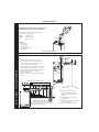
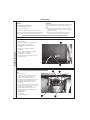
Your Ideal installation and servicing guide
See reverse for
excel
users guide
For details of document amendments, refer to page 3
HE C24, C28, C32
When replacing any part on this appliance use only spare parts that you can be
assured conform to the safety and performance specification that we require. Do not
use reconditioned or copy parts that have not been clearly authorised by Ideal Boilers.
November 2007
UIN 201279 A06
For the very latest copy of literature for specification purposes please visit our website
www.idealboilers.com where you will be able to download the relevant information in pdf format.
the nation’s favourite for
PLUMBING & HEATING SUPPLIES
FREE SHIPPING
SECURE PAYMENTS
on all orders over £100 to mainland UK
shop online with confidence
FINANCE AVAILABLE
PRICE MATCH
spread the cost with low interest rates
always get the best deals available
we have
H U G E
R E D U C T I O N S
ON THOUSANDS OF ITEMS
Boilers
Bathroom suites
Radiators
Kitchen sinks & taps
Heating controls
Showers
Pipes & ittings
Wet rooms
Cylinders
Towel warmers
Fires
Bathroom furniture
Renewable energy
& much more
visit our website
plumbnation.co.uk
CALL US ON
0844
800
3460
2
excel HE - Installation and Servicing
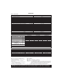
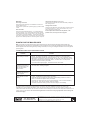
DOCUMENT AMENDMENTS
Relevant Installation changes implemented in this book from Mod Level ........... A05 (Oct 06) to A06 (Nov 07)
•
Page 4, Table 1 - General Data
New Maximum working pressure figures.
•
Page 7, Optional Extra Kits
Addition of High Level Flue Outlet Kit.
•
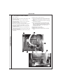
Page 40, Frame 63 - PCB Replacement
Note added re: antistatic precautions.
•
Page 42, Frame 66 - Air Pressure Switch Replacement
New photograph added showing correct orientation of air pressure switch.
•
Users Guide - Page 2, Important Notes
Additon of two new bullets into important notes.
Ideal Stelrad Group reserve the right to vary specification without notice
excel HE - Installation and Servicing
3
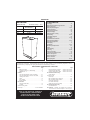
GENERAL
Table 1 - General Data
excel HE C24
Gas supply
Gas Supply Connection
Injector Size
Inlet Connection
Domestic Hot Water
Outlet Connection
Domestic Hot Water
Flow Connection
Central Heating
Return Connection
Central Heating
Flue Terminal Diameter
mm (in)
Average Flue Temp-Mass Flow Rate
Maximum Working Pressure (Sealed Systems)
bar (lb/in2)
Maximum Domestic Hot Water Inlet Pressure
bar (lb/in2)
Minimum Domestic Hot Water Inlet Pressure
bar (lb/in2)
Electrical Supply
Power Consumption
W
Fuse Rating
Water content
Central Heating
litre (gal)
Domestic Hot Water
Packaged Weight
kg (lb)
Maximum Installation Weight
kg (lb)
Boiler Casing Size
Height
mm (in)
Width
mm (in)
Depth
mm (in)
NOX Classification
IP Rating
excel HE C28
excel HE C32
I2H - G20 - 20mbar
Rp 1/2"
1.1
1.25
1.25
15mm copper compression
15mm copper compression
22mm copper compression
22mm copper compression
100 (4)
75oC - 14g/s
80oC - 16g/s
80oC - 18g/s
2.5 (36.3)
10.0 (145)
0.5 (7)
230 V ~ 50 Hz.
168
180
184
External : 3A Internal :
1.9 (0.42)
2.0 (0.44)
0.2 (0.044)
47 (103)
53 (117)
53 (117)
43 (95)
49 (108)
49 (108)
800 (31 1/2”)
450 (17 1/2”)
320 (12 5/8”)
Class 2
IP20
Table 2 - Performance Data - Central Heating
Burner pressure (hot)
G20
Input based on nett CV
Input based on gross CV
Output: Non condensing
70oC Mean Water temp.
Condensing
40oC Mean Water temp.
Gas consumption (Hot)
G20
Seasonal efficiency *
mbar
(in.w.g.)
kW
(btu/h)
kW
(btu/h)
kW
(btu/h)
kW
(btu/h)
l/s
(ft3/h)
(SEDBUK)
excel HE C24
Max
Min
13.4
5.0
(5.3)
(2.0)
24.4
15.2
(83,300)
(51,900)
27.1
16.9
(92,400)
(57,600)
23.4
14.2
(80,000)
(48,500)
25.1
15.3
(85,600)
(52,200)
0.700
0.40
89.0
50.4
Band B [ 86.4 ]%
excel HE C28
Max
Min
10.5
3.9
(4.2)
(1.6)
29.0
18.4
(98,900)
(62,800)
32.2
20.4
(109,900)
(69,600)
28.0
17.6
(95,500)
(60,000)
29.8
18.3
(101,700)
(62,400)
0.83
0.53
105.9
67
Band B [ 86.4 ]%
excel HE C32
Max
Min
12.9
3.8
(5.2)
(1.5)
33.4
19.0
(114,000)
(64,800)
37.1
21.1
(126,600)
(72,000)
32.0
17.9
(109,000)
(61,000)
34.3
18.9
(117,000)
(65,000)
0.96
0.54
122
69.4
Band B [ 86.3 ]%
*The value is used in the UK Government's Standard Assessment Procedure (SAP) for energy rating of dwellings.
The test data from which it has been calculated have been certified by a notified body.
Table 3 - Performance Data - Domestic Hot Water
HE C24 Max HE C24 Min
Max. Burner pressure (hot) G20 mbar (in.w.g.) 13.4 (5.3)
2.2 (0.9)
Input based on nett CV
kW (btu/h)
24.4 (83,300)
Input based on gross CV
kW (btu/h)
27.1 (92,400)
Output
kW (btu/h)
23.4 (80,000)
Gas consumption (Hot)
G20 l/s (ft3/h)
0.7 (89)
Flow 35oC temp. rise
l/m (gpm)
9.6 (2.1)
Flow 40oC temp. rise
l/m (gpm)
8.4 (1.8)
Domestic hot water specific rate l/m (gpm)
11.2 (2.5)
HE C28 Max HE C28 Min HE C32 Max HE C32 Min
10.5 (4.2)
1.5 (0.6)
12.9 (5.2)
1.6 (0.6)
29.0 (98,900)
33.4 (114,000)
32.2 (109,900)
37.1 (126,600)
28.0 (95,500)
32.0 (109,000)
0.83 (105.9)
0.96 (122)
11.5 (2.6)
13.1 (2.9)
10 (2.2)
11.5 (2.6)
13.4 (3.0)
15.3 (3.4)
Note. Quoted flow rates and temperature rises are those theoretically achievable. Flow rates measured during commissioning may differ (due,
for example, to resistance of domestic hot water pipe lengths and fittings or available dynamic gas pressures).
Note. Gas consumption is calculated using a
calorific value of 38.7 MJ/m3 (1038 Btu/ft3) gross or
34.9 MJ/m3 (935 Btu/ft3) nett
To obtain the gas consumption at a different
calorific value:
a . For l/s - divide the gross heat input (kW) by the
gross C.V. of the gas (MJ/m3)
3
b. For ft /h - divide the gross heat input (Btu/h) by
the gross C.V. of the gas (Btu/ft3)
Key to symbols
GB =
United Kingdom
IE = Ireland
(Countries of destination)
PMS = Maximum operating pressure of water
C12 C32 C52 = A room sealed appliance designed for connection via ducts to a horizontal
or vertical terminal, which admits fresh air to the burner and discharges the
products of combustion to the outside through orifices which, in this case,
are concentric. The fan is up stream of the combustion chamber.
I2H
= An appliance designed for use on 2nd Family gas, Group H only.
CAUTION. To avoid the possibility of injury during the installation, servicing or cleaning of
this appliance care should be taken when handling edges of sheet steel components
4
excel HE - Installation and Servicing
GENERAL
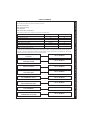
CONTENTS
excel HE
Natural Gas only
Boiler size
C24
C28
C32
Destination Country:
GB, IE
G.C. Appliance No.
(Benchmark No.)
PI No.
47 348 35
47 348 36
47 348 37
87 BP 46
87 BP 46
87 BP 46
Air Supply ..................................................................... 10
Benchmark Commissioning Checklist ..................... 58
Boiler Clearances ......................................................... 9
Boiler Exploded Diagram ....................................... 12,13
Condensate Drain ....................................................... 23
Electrical Connections ............................................... 26
Electrical Supply ......................................................... 10
Extension Ducts - Fitting ............................................. 18
Fault Finding ........................................................... 49-53
Flow Wiring Diagram .................................................. 29
Flue Fitting .............................................................. 15-18
Horizontal Flue Installation ........................................... 8
Roof Flue Kit Installation ....................................... 19-21
Gas Safety Regulations ................................................ 7
Gas Supply ..................................................................... 8
Installation ............................................................. 14-31
Mandatory Requirements ........................................ 7-11
Pump .......................................................................... 46
Safe Handling ................................................................ 6
Servicing ................................................................ 32-48
Short List of Parts ....................................................... 54
Thermostatic Radiator valves ................................... 10
Water and Systems .............................................. 10-12
Water Connections ..................................................... 24
80
3
x7
e
Water Treatment ......................................................... 12
Wiring Diagrams ................................................... 26-29
For GB, to comply with Building Regulations Part L1 (Part J in Scotland) the boiler should be fitted in accordance with the
manufacturer's instructions. Self-certification that the boiler has been installed to comply with Building Regulations can be
demonstrated by completing and signing the Benchmark Commissioning Checklist.
BENCHMARK COMMISSIONING CHECKLIST
Boiler
Page
Make and model ....................................................... 5
Appliance serial no. on data badge ...................... 13
SEDBUK No. % ......................................................... 4
Controls
Time and temperature control to heating ............. 27
Time and temperature control to hot water .......... 27
Heating zone valves .............................................. n/a
TRV's ...................................................................... 10
Auto bypass ............................................................ 11
Boiler interlock ....................................................... 10
For all boilers
Flushing to BS.7593 .............................................. 12
Inhibitor .................................................................. 12
Central heating mode
Heat input ................................................to be calculated
Page
Burner operating pressure ...... measure and record
Central heating flow temp. ...... measure and record
Central heating return temp. ... measure and record
For combination boilers only
Scale reducer .......................................................... 11
Hot water mode
Heat input ............................................................... n/a
Max. operating burner pressure ............................ n/a
Max. operating water pressure ............................. n/a
Cold water inlet temp ............................................ n/a
Hot water outlet temp. ........................................... n/a
Water flow rate at max. setting .............................. n/a
For condensing boilers only
Condensate drain .................................................. 23
For all boilers: complete, sign & hand over to customer
For assistance see Technical Helpline on the back page
NOTE TO THE INSTALLER: COMPLETE
THE BENCHMARK COMMISSIONING
CHECKLIST AND LEAVE THESE
INSTRUCTIONS WITH APPLIANCE
excel HE - Installation and Servicing
5
GENERAL
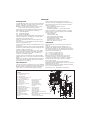
INTRODUCTION
Caution should be exercised during these operations.
The excel HE range of boilers are wall mounted, full sequence,
automatic spark ignition, low water content, fanned flue, high
efficiency, condensing, combination gas boilers.
Operatives should be knowledgeable in handling techniques
when performing these tasks and the following precautions
should be considered:
Note. Due to the high efficiency of the boiler a plume of water
vapour will form at the terminal during operation.
•
•
•
Central heating (CH) and instantaneous domestic hot water
(DHW) outputs are fully modulating with a maximum of :
C24
23.4kW (80,000 Btu/h)
C28
28.0kW (95,500 Btu/h)
C32
32.0kW (109,000 Btu/h)
Grip the boiler as described in Frame 28.
Be physically capable.
Use PPE as appropriate, e.g. gloves, safety footwear.
During all manoeuvres and handling actions, every attempt
should be made to ensure the following unless unavoidable
and/or the weight is light.
Variable CH and DHW temperature controls are fitted on the
user control.
•
•
•
•
•
•
•
The boiler casing is of white painted mild steel with a plastic
drop down controls access door.
OPERATION
The boiler temperature controls are located behind the controls
access door.
With no demand for CH, the boiler fires only when DHW is
drawn off.
The main heat exchanger is made of copper, the high efficiency
recuperator is made of stainless steel and the DHW plate heat
exchanger is made of stainless steel.
When there is a demand for CH, the heating system is
supplied at the selected temperature of between 38oC and
82oC, until DHW is drawn off. The full output from the boiler is
then directed via the diverter valve to the plate heat exchanger to
supply a nominal DHW draw-off of :
The boilers are supplied fully assembled with DHW plate heat
exchanger, diverter valve, circulating pump, pressure gauge,
safety valve and CH expansion vessel.
The boiler is suitable for connection to fully pumped, sealed
water systems ONLY. Adequate arrangements for completely
draining the system by provision of drain cocks MUST be
provided in the installation pipework.
A system bypass is not required when TRV’s are fitted to ALL
radiators (see Frame 5). The boiler incorporates an automatic
bypass.
Pipework from the boiler is routed downwards as standard, but
may be routed upwards behind the boiler using the stand-off
frame (supplied in a separate kit).
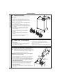
SAFE HANDLING
This boiler may require 2 operatives to move it to its installation
site, remove it from its packaging and during movement into its
installation location. Manoeuvring the boiler may include the
use of a sack truck and involve lifting, pushing and pulling.
1
Keep back straight.
Avoid twisting at the waist.
Avoid upper body/top heavy bending.
Always grip with the palm of the hand.
Use designated hand holds.
Keep load as close to the body as possible.
Always use assistance if required.
C24 9.6 l/min (2.1 GPM) at 35oC rise.
C28 11.5 l/min (2.6 GPM) at 35oC rise.
C32 13.1 l/min (2.9 GPM) at 35oC rise.
Note. Quoted flow rates and temperature rises are those
theoretically achievable. Flow rates measured during
commissioning may differ (due, for example, to resistance of
domestic hot water pipe lengths and fittings or available
dynamic gas pressures).
Due to system variations and seasonal temperature
fluctuations DHW flow rates/temperature rise will vary, requiring
adjustment at the draw off tap.
At low DHW draw-off rate the maximum temperature is limited
to 65o C by the modulating gas control.
Refer also to Frame 1 - 'Boiler Water Circuit Diagram'.
34
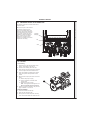
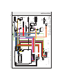
BOILER WATER CIRCUIT DIAGRAM
25
24
37
23
LEGEND
1. DHW plate heat exchanger
2. DHW flow switch
3. DHW outlet pipe
4. Domestic cold water inlet cock
5. 3 - way diverter valve
6. Main circuit drainage cock
7. CH flow cock
8. By-pass valve
9. CH return cock
10. 3 Bar pressure relief valve
11. Gas cock
12. Expansion vessel
13. Gas valve inlet pressure tap
14. Modulating gas valve
15. Burner pressure tap
16. Flame detection electrode
17. Ignition electrodes
18. Burner
19. Combustion chamber
20. Primary heat exchanger
21. Fan
6
27
22
35
36
21
22.
23.
24.
25.
26.
27.
28.
29.
30.
31.
32.
33.
34.
35.
36.
37.
20
Air pressure switch
19
Venturi device
Flue outlet pipe
17
Air intake pipe
16
Automatic air vent
18
Overheat thermostat
Pump
15
Pump vent plug
14
CH thermistor
CH flow switch
13
DHW thermistor
CH temperature pressure gauge
Recuperator
Sensor dry fire/condensate blockage thermistor
Condensate pipe
Collector flue condensate
12
1
30
10
33
32
26
2
28
29
31
5
11
ix7410
9
8
7
6
4
3
excel HE - Installation and Servicing
GENERAL
OPTIONAL EXTRA KITS
•
FLUING:
Flue Extension Ducts. ('D' Pack - 1000mm long).
C24-up to 3m
C28-up to 2.675m
C32-up to 1.725m
o
90 Elbow Kit (60/100 dia maximum no. per installation).
C24-up to 2 elbows
C28-up to 2 elbows
C32-up to 1 elbow
o
45 Elbow Kit (60/100 dia maximum no. per installation).
C24-up to 2 elbows
C28-up to 2 elbows
C32-up to 1 elbow
Roof Flue Kit (80/125)
C24-up to a maximum length of 16 m
C28-up to a maximum length of 12 m
C32- up to a maximum length of 8 m
Roof Flue Extension Duct Kit (80/125)
Pitched Roof Tile (for roof flue kit)
Flat Roof Tile (For roof flue kit)
Ridge Tile Flue Terminal (For twin flue kit)
Adaptor (60/100 to 80/125)
Twin Flue Kit (80/80)
Twin Flue Kit (60/60)
Vertical Connector (60/100)
Vertical Outlet Flue Kit with Elbow (60/100)
C24-up to a maximum length of 5.5 m
C28-up to a maximum length of 4 m
C32- up to a maximum length of 2.5 m
80mm Extension Duct
60mm Extension Duct
o
90 Elbow (80mm male/female)
o
90 Elbow (60mm male/female)
o
45 Elbow (80mm male/female)
o
45 Elbow (60mm male/female)
Flue Finishing Kit
o
90 Elbow (80/125)
o
45 Elbow (80/125)
Slip Coupling (80mm)
Slip Coupling (60mm)
High Level Flue Outlet Kit
OTHER OPTION KITS:
Mechanical Programmer (24 hour)
Electronic Programmer (7 day)
Condensate Pump Kit
Siphon Kit
Stand Off Kit
Pre-Piping Frame Kit
SAFETY
Current Gas Safety (installation and use) regulations or rules
in force:
The appliance is suitable only for installation in GB and IE and
should be installed in accordance with the rules in force.
In GB, the installation must be carried out by a CORGI
Registered Installer, or in IE a competent person. It must be
carried out in accordance with the relevant requirements of the:
•
Gas Safety (Installation and Use) Regulations.
excel HE - Installation and Servicing
•
•
The appropriate Building Regulations either The Building
Regulations, The Building Regulations (Scotland), Building
Regulations (northern Ireland).
The Water Fittings Regulations or Water bye-laws in
Scotland.
The Current I.E.E. Wiring Regulations.
Where no specific instructions are given, reference should be
made to the relevant British Standard Code of Practice.
In IE, the installation must be carried out by a Competent
Person and installed in accordance with the current edition of
I.S.813 "Domestic Gas Installations", the current Building
Regulations and reference should be made to the current ETCI
rules for electrical installation.
Detailed recommendations are contained in the following British
Standard Codes of Practice:
BS. 5440:1
Flues (for gas appliances of rated input not
exceeding 70 kW).
BS. 5440:2
Ventilation (for gas appliances of rated input not
exceeding 70 kW).
BS. 5449
Forced circulation hot water systems.
BS. 5546
Installation of gas hot water supplies for
domestic purposes (2nd Family Gases)
BS. 6798
Installation of gas fired hot water boilers of rated
input not exceeding 70 kW.
BS. 6891
Low pressure installation pipes.
Health & Safety Document No. 635.
The Electricity at Work Regulations, 1989.
The manufacturer’s notes must NOT be taken, in any way, as
overriding statutory obligations.
IMPORTANT. These appliances are CE certificated for safety
and performance. It is, therefore, important that no external
control devices, e.g. flue dampers, economisers etc., are
directly connected to these appliances unless covered by these
Installation and Servicing Instructions or as otherwise
recommended by Ideal Stelrad Group in writing. If in doubt
please enquire.
Any direct connection of a control device not approved by Ideal
Stelrad Group could invalidate the certification and the normal
appliance warranty. It could also infringe the Gas Safety
Regulations and the above regulations.
SAFE HANDLING OF SUBSTANCES
Care should be taken when handling the boiler insulation
panels, which can cause irritation to the skin. No asbestos,
mercury or CFCs are included in any part of the boiler or its
manufacture.
LOCATION OF BOILER
The boiler must be installed on a flat and vertical wall, capable
of adequately supporting the weight of the boiler and any
ancillary equipment.
The boiler may be fitted on a combustible wall and insulation
between the wall and the boiler is not necessary, unless
required by the local authority.
For electrical safety reasons there must be no access available
from the back of the boiler.
The boiler must not be fitted outside.
Timber Framed Buildings
If the boiler is to be fitted in a timber framed building it should
be fitted in accordance with the Institute of Gas Engineering
document IGE/UP/7:1998.
Bathroom Installations
This appliance is rated IP20.
7
GENERAL
The boiler may be installed in any room or internal space,
although particular attention is drawn to the requirements of the
current IEE (BS.7671) Wiring Regulations and, in Scotland, the
electrical provisions of the building regulations applicable in
Scotland, with respect to the installation of the boiler in a room
or internal space containing a bath or shower. For IE reference
should be made to the current ETCI rules for electrical
installations and I.S. 813:2002.
If the appliance is to be installed in a room containing a bath or
shower then, providing water jets are not going to be used for
cleaning purposes (as in communal baths/showers), the
appliance can be installed in Zone 3, as detailed in BS.7671.
Compartment Installations
A compartment used to enclose the boiler should be designed
and constructed specially for this purpose.
An existing cupboard or compartment may be used, provided
that it is modified for the purpose.
In both cases, details of essential features of cupboard /
compartment design, including airing cupboard installation,
are to conform to the following:
BS 6798 (No cupboard ventilation is required - see ‘Air
Supply’ for details).
The position selected for installation MUST allow adequate
space for servicing in front of the boiler.
For the minimum clearances required for safety and
subsequent service, see the wall mounting template and
Frame 2. In addition, sufficient space may be required to
allow lifting access to the wall mounting plate.
GAS SUPPLY
The local gas supplier should be consulted, at the installation
planning stage, in order to establish the availability of an
adequate supply of gas. An existing service pipe must NOT be
used without prior consultation with the local gas supplier.
The boiler MUST be installed on a gas supply with a governed
meter only.
A gas meter can only be connected by the local gas supplier or
by a CORGI registered engineer. In IE by a competent person.
An existing meter should be checked, preferably by the gas
supplier, to ensure that the meter is adequate to deal with the
rate of gas supply required.
IMPORTANT.
Installation pipes must be fitted in accordance with BS.6891. In
IE refer to IS.813:2002. Pipework from the meter to the boiler
MUST be of an adequate size, i.e. not less than 22mm O.D.
copper or 3/4" B.S.P. iron.
The complete installation MUST be tested for gas soundness
and purged as described in the above code.
FLUE INSTALLATION
Pluming will occur at the terminal so terminal positions where
this could cause a nuisance should be avoided.
The flue must be installed in accordance with the
recommendations of BS. 5440-1: 2000.
In IE refer to I.S. 813:2002.
The following notes are intended for general guidance:
1. The boiler MUST be installed so that the terminal is exposed
to external air.
2. It is important that the position of the terminal allows the free
passage of air across it at all times.
3. Minimum acceptable spacing from the terminal to obstructions
and ventilation openings are specified in Table 4.
8
4. Where the lowest part of the terminal is fitted less than 2m
(6'6") above a balcony, above ground or above a flat roof to
which people have access then the terminal MUST be
protected by a purpose designed guard.
Terminal guards are available from boiler suppliers. (Ask for
TFC flue guard model no. K6 - round, plastic coated). In case
of difficulty contact:
Grasslin (UK) Ltd.
Tel. + 44 (0) 01732 359 888
Tower House, Vale Rise Fax. + 44 (0) 01732 354 445
Tonbridge. Kent TN9 1TB
www.tfc-group.co.uk
Ensure that the guard is fitted centrally.
5. The flue assembly shall be so placed or shielded as to
prevent ignition or damage to any part of any building.
6. The air inlet/products outlet duct and the terminal of the
boiler MUST NOT be closer than 25mm (1") to combustible
material. Detailed recommendations on the protection of
combustible material are given in BS. 5440-1:2000.
IMPORTANT. It is absolutely essential to ensure, in practice,
that products of combustion discharging from the terminal
cannot re-enter the building or any other adjacent building
through ventilators, windows, doors, other sources of natural
air infiltration, or forced ventilation / air conditioning.
If this should occur the appliance MUST be turned OFF,
labelled as 'unsafe' until corrective action can be taken.
TERMINAL
The terminal assembly can be adapted to accommodate
various wall thicknesses. Refer to Frame 11.
Table 4
Terminal Position
Minimum Spacing
1.
Directly below, above or alongside of
another openable window, air vent,
or other ventilation opening.
2.
Below guttering, drain pipes or soil pipes
25 mm
(1")
3.
Below eaves
25 mm
(1")
4.
Below balconies or a car port roof
25 mm
(1")
5.
From vertical drain pipes or soil pipes
150 mm
(6")
6.
From an internal or external corner or
to a boundary along side the terminal.
100 mm
(4")
7.
Above adjacent ground, roof or
balcony level
300 mm (12")
8.
From a surface or a boundary
facing the terminal
600 mm (24")
9.
From a terminal facing a terminal
300 mm (12")
1200 mm (48")
10. From an opening in a car port
(e.g. door or window) into dwelling
1200 mm (48")
11. Vertically from a terminal on the
same wall
1500 mm (60")
12. Horizontally from a terminal on the wall
Vertical Terminals
13. Above the roof pitch with roof slope
of all angles to air inlet.
Above flat roof to air inlet.
14. From single wall face
From corner walls
Twin Flue Applications
15. Centre distance between air inlet
and flue outlet ducts
300 mm (12")
300 mm (12")
300 mm (12")
600 mm (24")
1000 mm (40")
120mm (5")
excel HE - Installation and Servicing
GENERAL
2
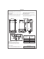
BOILER DIMENSIONS, SERVICES & CLEARANCES
The following minimum clearances must be maintained for
operation and servicing.
Where the space into which the boiler is going to be
installed is less than the length of flue required the flue
must be fitted from the outside.
Additional space will be required for installation, depending
upon site conditions.
Side and Rear Flue
a. Provided that the flue hole is cut accurately, e.g. with a core
drill, the flue can be installed from inside the building
where wall thicknesses do not exceed 600mm (24").
10 (3/8")
all dimensions in mm (in)
Installation from inside ONLY
b. If a core boring tool is to be used inside the building the
space in which the boiler is to be installed must be at least
wide enough to accommodate the tool.
10 (3/8")
from case
320 (12 5/8")
450 (17 1/2")
119 (4 3/4")
177 (7")
331 (13")
200 (8") **
Flue
terminal
800
(31 1/2")
C
L of
water & gas
connections
ix7378
C
L of
condensate
drain
100 (4")*
35
(13/8")
470 (18 1/2")
109
(41/4")
SIDE FLUE ONLY **
33 35 62
53 65 60 25
(13/8") (13/8") (21/2") (21/8") (25/8") (21/2")Condensate
CH Flow
Drain
CH Return
Pressure Relief Outlet
DHW Inlet
DHW Outlet
Gas Inlet
Front clearance
The minimum front clearance when built in to a
cupboard is 5mm (1/4") from the cupboard door but
450mm (17 3/4") overall clearance is still required,
with the cupboard door open, to allow for servicing.
*
Bottom clearance
Bottom clearance after installation can be reduced to 5mm.
However, 100mm must be available for servicing.
excel HE - Installation and Servicing
Horizontal length of flue
from boiler to
outside wall
C24
C28
C32
Top clearance
required (MIN.)
Dim. A
0.5 m
0.5 m
0.5 m
200 mm (7 7/8")
1.0 m
1.0 m
1.0 m
200 mm (7 7/8")
1.5 m
1.5 m
1.5 m
230 mm (9")
2.0 m
2.0 m 1.725 m 250 mm (9 13/16")
2.5 m
2.5 m
3.0 m 2.675 m
N/A
260 mm (10 1/4")
N/A
280 mm (11")
REAR FLUE ONLY **
MIN. Top clearance required = 200 mm (8")
9
GENERAL
AIR SUPPLY
It is NOT necessary to have a purpose-provided air vent in
the room or internal space in which the boiler is installed.
Neither is it necessary to ventilate a cupboard or
compartment in which the boiler is installed, due to the low
surface temperatures of the boiler casing during operation;
therefore the requirements of BS 6798, Clause 12, and BS
5440:2 may be disregarded.
WATER CIRCULATION SYSTEM
IMPORTANT.
A minimum length of 1 metre of copper pipe MUST be fitted
to both flow and return connections from the boiler before
connection to any plastic piping.
The central heating system should be in accordance with
BS.6798 and, in addition, for smallbore and microbore
systems, BS.5449.
WATER TREATMENT - see Frame 6
BOILER CONTROL INTERLOCKS
Ideal Stelrad Group recommend that heating systems
utilising full thermostatic radiator valve control of temperature
in individual rooms should also be fitted with a room
thermostat controlling the temperature in a space served by
radiators not fitted with such a valve as stated in BS. 5449.
Central heating systems controls should be installed to
ensure the boiler is switched off when there is no demand for
heating or hot water.
3
When thermostatic radiator valves are used, the space heating
temperature control over a living / dining area or hallway having
a heating requirement of at least 10% of the boiler heat output
should be achieved using a room thermostat, whilst other
rooms are individually controlled by thermostatic radiator valves.
ELECTRICAL SUPPLY
WARNING.
This appliance must be earthed.
Wiring external to the appliance MUST be in accordance with
the current I.E.E. (BS.7671) Wiring Regulations and any local
regulations which apply. For IE reference should be made to
the current ETCI rules for electrical installations.
The point of connection to the mains should be readily
accessible and adjacent to the boiler.
CONDENSATE DRAIN Refer to Frame 27
A condensate drain is provided on the boiler. This drain must
be connected to a drainage point on site. All pipework and
fittings in the condensate drainage system MUST be made of
plastic - no other materials may be used.
IMPORTANT.
Any external runs must be insulated.
The drain outlet on the boiler is standard 21.5mm (3/4”)
overflow pipe.
SYSTEM REQUIREMENTS - Central Heating
Notes
Safety valve setting
bar
3.0
a. The method of filling, refilling, topping up or flushing sealed
primary hot water circuits from the mains via a temporary
hose connection is only allowed if acceptable to the local
water authority.
Vessel charge pressure
bar
0.5 to 0.75
System pre-charge pressure bar
System volume
(litres)
b. Antifreeze fluid, corrosion and scale inhibitor fluids suitable
for use with boilers having copper heat exchangers may be
used in the central heating system.
25
50
75
100
125
150
175
190
200
250
300
For other system volumes
multiply by the factor across
Advice should be sought from a local water treatment
company.
General
1. The installation must comply with all relevant national and
local regulations.
2. The installation should be designed to work with flow
temperatures of up to 82oC.
3. All components of the system must be suitable for a
working pressure of 3 bar and temperature of 110oC. Extra
care should be taken in making all connections so that the
risk of leakage is minimised.
The following components are incorporated within the
appliance:
10
a.
Circulating pump.
b.
Safety valve, with a non-adjustable preset lift pressure
of 3 bar.
c.
Pressure gauge, covering a range of 0 to 4 bar.
d.
A 7-litre expansion vessel, with an initial charge
pressure of 0.75 bar.
None
1.0
Expansion vessel
volume (litres)
1.6
3.1
4.7
6.3
7.8
9.4
10.9
11.9
12.5
15.6
18.8
1.8
3.7
5.5
7.4
9.2
11.0
12.9
14.0
14.7
18.4
22.1
0.063
0.074
4. 'Make-up' Water. Provision must be made for replacing
water loss from the system, either :
a.
From a manually filled 'make-up' vessel with a readily
visible water level. The vessel should be mounted at
least 150mm above the highest point of the system and
be connected through a non-return valve to the system,
fitted at least 150mm below the 'make-up' vessel on the
return side of the radiators.
or
continued . . . . . .
excel HE - Installation and Servicing
GENERAL
4
SYSTEM REQUIREMENTS - CH (continued) and Hot Water
b.
Where access to a 'make-up' vessel would be difficult, by
pre-pressurisation of the system.
The maximum cold water capacity of the system should
not exceed 143 litres, if not pressurized. However, if the
system is to be pressurized, the efficiency of the
expansion vessel will be reduced and a larger vessel (or
smaller system volume) may be necessary. If the
capacity of the vessel is not considered sufficient for this,
or for any other reason, an additional vessel MUST be
installed on the return to the boiler.
Guidance on vessel sizing is given in Frame 3.
5. Filling. The system may be filled by the following method:
a.
Water Flow Rate and Pressure Loss
Max CH Output
kW
23.4
28
32
(Btu/h) (80,000) (95,500) (109,000)
Water flow rate
l/sec
0.28
0.33
0.38
(gal/min)
(3.7)
(4.4)
(5.0)
20
20
20
(oF)
(36)
(36)
(36)
Head available for m.w.g.
3.3
1.5
1.1
(10.8)
(4.9)
(3.6)
Temp. Differential
system pump.
o
C
(ft.w.g.)
Through a temporary hose connection from a 'draw-off'
tap, supplied from a service pipe under mains pressure.
Where the mains pressure is excessive a pressure
reducing valve must be used to facilitate filling.
Mains
water supply
When installing the filling device it must be connected as
shown below, to fully comply with the water regulations.
This may involve the fitting of an additional WRAS
approved isolator valve to the mains supply.
i.
Thoroughly flush out the whole system with cold
water.
CH Return
Hose unions
ii. Fill and vent the system until the pressure gauge
registers 1.5 bar and examine for leaks.
Additional
stop valve
iii. Check the operation of the safety valve by raising the
water pressure until the valve lifts. This should occur
within 0.3 bar of the preset lift pressure.
iv. Release water from the system until the minimum
system design pressure is reached: 1.0 bar if the
system is to be pre-pressurised.
DOMESTIC HOT WATER
1. The domestic hot water service must be in accordance with
BS 5546 and BS 6700.
2. Refer to Table 1 for minimum and maximum working
pressures.
3. The boilers are suitable for connection to most types of
washing machine and dishwasher appliances.
Temporary hose
(disconnect after filling)
Ecl 6053
b.
Double check valve
assembly
(note direction of flow)
Hot and cold water supplies to the shower are of equal
pressure.
5. Hard Water Areas
Where the water hardness exceeds 200mg/litre, it is
recommended that a proprietary scale reducing device is
fitted into the boiler cold supply within the requirements of
the local water company.
IMPORTANT
4. When connecting to suitable showers, ensure that:
a.
5
Provision MUST be made to accommodate the expansion of
The cold inlet to the boiler is fitted with an approved anti- DHW contained within the appliance, if a non-return valve is
fitted to the DHW inlet.
vacuum or syphon non-return valve.
SYSTEM BALANCING
The boiler does not need a bypass.
BALANCING
1. Set the programmer to ON.
Close the manual or thermostatic valves on all radiators,
leaving the twin lockshield valves (on the radiators
referred to above) in the OPEN position.
Turn up the room thermostat and adjust these lockshield
valves to give boiler flow and return temperatures not
more than 20oC apart.
2. Open all manual or thermostatic radiator valves
and adjust the lockshield valves on the remaining
radiators, to give around 20oC temperature drop at
each radiator.
3. Adjust the room thermostat and programmer to
NORMAL settings.
These valves should now be left as set.
excel HE - Installation and Servicing
11
GENERAL
6
WATER TREATMENT
CENTRAL HEATING
DOMESTIC HOT WATER
The excel HE range of boilers have a copper main heat
exchanger and a stainless steel high efficiency heat
exchanger.
In hard water areas where main water can exceed 200ppm
Total Hardness (as defined by BS 7593:1993 Table 2) a
scale reducing device should be fitted into the boiler cold
supply within the requirements of the local water company.
The use of artificially softened water, however, is not
permitted.
Ideal Stelrad Group recommend the use of Fernox
Qantomat, GE Betz Sentinel Combiguard and Calmag
CalPhos I scale reducing devices, which must be used in
accordance with the manufacturers' instructions. For further
information contact:
IMPORTANT.
The application of any other treatment to this product
may render the guarantee of Ideal Stelrad Group
invalid.
Ideal Stelrad Group recommend Water Treatment in
accordance with the Benchmark Guidance Notes on
Water Treatment in Central Heating Systems.
If water treatment is used Ideal Stelrad Group recommend
only the use of FERNOX-COPAL or MB1, GE BETZ SENTINEL X100
or Salamander Corrosion Guard inhibitors and associated
water treatment products, which must be used in accordance
with the manufacturers' instructions.
Notes.
1. It is most important that the correct concentration of the
water treatment products is maintained in accordance with
the manufacturers' instructions.
2. If the boiler is installed in an existing system any unsuitable
additives MUST be removed by thorough cleansing. BS
7593:1992 details the steps necessary to clean a domestic
heating system.
3. In hard water areas, treatment to prevent lime scale may be
necessary - however the use of artificially softened water is
NOT permitted.
4. Under no circumstances should the boiler be fired before
the system has been thoroughly flushed.
7
Fernox Manufacturing Co. Ltd
Cookson Electronics
Forsyth Road
Sheerwater
Woking
Surrey GU21 5RZ
Tel: +44 (0) 1799 521133
Sentinel Performance Solutions
The Heath Business & Technical Park
Runcorn
Cheshire
WA7 4QX
Tel: 0800 389 4670
www.sentinel-solutions.net
Salamander Engineering Ltd
Unit 24 Reddicap Trading Estate
Sutton Coldfield
West Midlands B75 7BU
Tel: +44 (0) 121 3780952
Calmag Ltd.
Unit 4-6, Crown Works
Bradford Road
Sandbeds, Keighley
West Yorkshire BD20 5LN
Tel: +44 (0) 1535 210 320
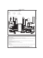
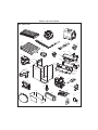
BOILER ASSEMBLY - Exploded View Legend
1. Main heat Exchanger
26. Controls fascia
42. Panel front sealing
2. Fan
27. Knob potentiometer
43. Casing LH side panel
5. Recuperator
28. Panel control cover
44. Casing RH side panel
6. Burner
29. Panel control support
45. Casing front panel
8. Injectors
30. Panel user wiring cover
46. Casing bottom panel
9. Detection electrode
31. Main PCB
50. Gas valve
10. Ignition electrode LH & RH
33. Pressure gauge
51. Condensate blockage thermistor
17. Safety Valve
34. Lens clear
52. Overheat thermostat
19. Pump head
35. Expansion PCB
53. Expansion vessel
20. Divertor valve Actuator
36. Mains switch
56. Combustion chamber insulation
21. Auto air vent valve
40. Ignition unit NAC
57. Thermistor waterset CH & DHW
25. Casing controls door
41. Air pressure switch
58. Plate Heat Exchanger
12
excel HE - Installation and Servicing
8
INSTALLATION
INSTALLATION
BOILER ASSEMBLY - Exploded View
53
Flue gas
sampling
point
41
43
8
5
2
51
40
50
42
17
52
6
56
45
1
Data
Plate
20
44
58
10
9
21
57
84
74
ex
19
46
28
30
31
34
35
29
User Data
Plate
26
27
25
36
33
excel HE - Installation and Servicing
13
9
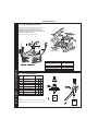
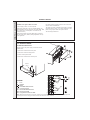
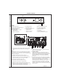
UNPACKING
The boiler is supplied fully
assembled in one Pack A, together
with a standard flue assembly for
lengths up to 775mm, rear or side
flue outlet, in Pack B.
Pack A Contents
Unpack and check the contents.
Refer to Frame 10 for Unpacking.
A
A
The boiler
F
1 year guarantee form
B
Hardware pack and fittings
G
Flue Restrictor - 1 off
24 kW - 39mm
28 kW - 43mm
32 kW - 45mm
C
Wall mounting plate
D
These Installation & Servicing/
User’s instructions
E
Wall mounting template
B
E
C
D
F
nm7407
G
Hardware Pack & Fittings
Isolation ball valve - CH - 2 off
J
B
Isolation ball valve - DHW - 1 off
K
M5x10 pozi pan screw ZP - 1 off
C
3/4" sealing washer - 2 off
L
Turret clamp - 1 off
D
Bulkhead elbow - 1 off
M
Pressure relief valve discharge pipe - 1 off
E
12mm sealing washer - 2 off
N
Pressure relief valve discharge pipe back nut - 1 off
F
Gas cock - 1 off
P
Pressure relief valve discharge pipe 15mm olive - 1 off
A
G
Gas cock washer - 1 off
H
Wallplug - 2 off
No 14x2in wood screw rd hd black - 2 off
B
F
E
A
G
J
L
C
N
D
H
K
P
M
ix7429
INSTALLATION
INSTALLATION
B
Pack B Contents
A Flue turret
A
B Flue terminal
ix7408
14
excel HE - Installation and Servicing
INSTALLATION
INSTALLATION
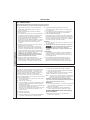
10 PACKAGING REMOVAL
4
1. Cut and remove straps.
2. Remove literature and wall
mounting template.
3. Lift off outer sleeve.
4. Lift off top tray.
5. Leave boiler in bottom tray to
protect exposed boiler
connections during wall hanging.
3
Note. Hardware pack contained within
bottom tray at back of boiler. Ensure
components are withdrawn before
discarding bottom tray.
5
ix7441
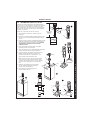
11 DETERMINING THE FLUE LENGTH AND FLUE PACKS REQUIRED
For the 100mm concentric flue system
Dimension X - Wall thickness.
Dimension L - Wall thickness plus boiler spacing.
Dimension R - Wall thickness plus boiler spacing.
Note.
FLUE KITS
Pack B - supplied as standard
Pack D - optional extension kit for side flue or rear flue outlet.
Refer to 'Flue Extension Ducts'
90o Elbow Kit - resistance is equivalent to 1.5m length of flue pipe
45o Elbow Kit - resistance is equivalent to 1.0m length of flue pipe
Total Flue length dimension
1. The flue duct MUST be
inclined at 1.5 degrees to
the horizontal to allow
condensate to drain back
into the boiler and out
through the condensate
drain. (Only necessary if
using one or more 'D'
extension duct packs)
Flue
Rear flue
dim. X+177
L.H. Side flue
dim. L+331
RH Side flue
dim. R+119
Extra packs
required
Boiler
Size
Up to 775 mm
Up to 775 mm
Up to 775 mm
none
C24, C28, C32
Up to 1725 mm
Up to 1725 mm
Up to 1725 mm
Pack D - 1 off
C24, C28, C32
Up to 2675 mm
Up to 2675 mm
Up to 2675 mm
Pack D - 2 off
C24, C28
Up to 3000 mm
Up to 3000 mm
Up to 3000 mm
Pack D - 3 off
C24
25 (1")
177 (7")
25 (1")
119 (43/4")
331 (13")
RH
Side
ix7416
450
(171/2")
LH
Side
Rear
R
Side flue length
excel HE - Installation and Servicing
X
Rear flue length
L
450
(171/2")
Side flue length
15
INSTALLATION
12 FLUE ASSEMBLY - Exploded View
IMPORTANT. DO NOT fit flue restrictor if flue
length is greater than 775 mm ('B' Pack).
2
An optional flue duct extension kit is required for
wall thicknesses greater than :
LH Side
420mm (161/2")
RH Side
630mm (243/4")
Rear
600mm (235/8")
1
3
4
5
ix7430
LEGEND
1. Flue Elbow.
2. Flue Assembly.
3. Flue Restrictor.
4. M5 x 10 pozi pan screw.
5. Turret Clamp.
Rear flue arrangement shown
13 WALL MOUNTING TEMPLATE
Extended
2 centre
line
Note.
The template shows the positions of the fixing
holes and the rear flue outlet hole centre for
standard installation. Care MUST be taken to
ensure the correct holes are drilled.
1
175mm
2. If fitting a side flue extend the flue centre line onto
the side wall and measure in 175mm for
standard installation.
T IN
MOUN
WA L L
L AT E
P
M
E
T
Note. If using stand-off kit distance increases to
211mm.
G
See wall mounting template
10
20
30
50
60
80
C24
17
ix74
V
C28
0.5
C32
1.0
3. Mark onto the wall the following:
1.5
2.0
2.5
3.0
"H" = Distance in metres from side
of the boiler to the side wall
ix7418
FLUE
OUTLET
1. Tape template into the selected position. Ensure
squareness by hanging a plumbline as shown.
16
305
See
Note
Note. If wall thickness is greater than 305mm then
dimension "H" must be reduced by the same amount and
the offset may be adjusted accordingly.
a The wall mounting plate screw
positions (choose one from each
group).
b. The position of the flue duct hole
(see diagram).
Note. Mark the centre of the hole as well
as the circumference
4. Remove the template from the wall.
excel HE - Installation and Servicing
INSTALLATION
14 PREPARING THE WALL
IMPORTANT.
Ensure that, during the cutting operation, masonry
falling outside of the building does not cause damage
or personal injury.
Rear flue only
5" diameter hole
1. Cut the flue hole (preferably with a 5" core boring
tool), ensuring that the hole is square to the wall.
Both wall faces immediately around the cut hole
should be flat.
Side flue only
5" diameter hole
X
Note. Check all of the hole
positions before drilling.
7419
Section
through wall
15 CUTTING THE FLUE - REAR Wall thicknesses of 114 to 600mm
Notes.
a. If using the extension ducts go to Frame 17, 18 and 19.
b. If the stand-off frame is used it is essential add 33mm to
'X' the measured wall thickness when marking the flue
(this will allow for the fitted frame).
1. Measure and note wall thickness X. Refer to Frame 11.
cla7841
3. To ensure the tube is cut square, mark the flue all the way
around.
OUTLET
2. Add 105mm (4 1/8") to dimension X and, measuring from
the ring, cut both outer and inner tube. Ensure support
spring clip is in position to facilitate cutting.
16 CUTTING THE FLUE - LH OR TO RH SIDE
Wall thicknesses of 114 to 420mm LH side or to 630mm RH side
FLUE
Note. If using the extension ducts go to Frame 17,
18 and 19.
2. Add 284mm (11 3/16") to dimension L or 72mm
(2 13/16") to dimension R and, measuring from
the ring, cut both outer and inner tube. Ensure
support spring clip is in position to facilitate
cutting.
cla7841
1. Measure and note side flue length L or R.
Refer to Frame 11.
3. To ensure the tube is cut square, mark the flue
all the way around.
excel HE - Installation and Servicing
17
INSTALLATION
17 FLUE EXTENSION DUCTS - For flue lengths greater than 775mm
Pack D Flue extension duct kit contents
Extension duct & clamp
1.0m (39") long
Wall plugs - 2 off
Clamp screws - 2 off
ix7411
Flue duct support
Washers - 2 off
Support fixing screws - 2 off
18 FLUE EXTENSION DUCTS - continued
Use a maximum of 3m extended flue ONLY (C24)
(R or L)
Use a maximum of 2.675m extended flue ONLY (C28)
Use a maximum of 1.725m extended flue ONLY (C32)
General arrangement
FLUE
OUTLET
1. A maximum of 2 extension ducts for the C24/
C28 and a maximum of 1 extension duct for the
C32 (one suitably cut) plus the standard flue
duct may be used together.
2. Flue extensions of greater length than 1m (39")
should be supported with the bracket provided,
suitably adjusted. Refer to Frame 17.
ex7786
Note. Side flue shown
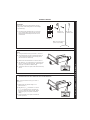
19 FITTING THE KIT
1. Fit the inner flue extension duct onto the
inner flue duct.
2. Fit the outer flue extension duct onto the
outer air duct.
1
3. Repeat steps 1 and 2 if a second flue
extension is required.
4. Measure and mark the flue length
required onto the flue, measuring from
the ring near the terminal. (Refer to
Frames 11 and 16 for the detail of flue
length calculation.)
2
Measure from
this
RING
mxhe7843
5. To ensure a square cut, mark the flue all
the way around.
6. De-burr the cut edges.
18
excel HE - Installation and Servicing
INSTALLATION
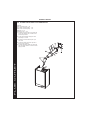
20 FITTING THE OPTIONAL ROOF FLUE KIT (Flat or Pitched)
Note.
A flat or pitched roof flashing plate (not supplied) is required before
proceeding with the installation of this kit.
This kit is suitable for both flat and pitched roof terminations, using a
concentric flue to run vertically from the top of the boiler and terminating
above roof level.
Connection to the top of the boiler is made using both a separately
supplied vertical connector and a 80/125 adaptor.
WEATHER PROOFING
Where the flue passes through the roof line an
adequate seal must be made. This is
achieved by using either:
-
Flat roof weather collar
or
-
Universal weather collar.
ACCESSORIES
Flue Duct Extension Kits are available for flue
lengths extending beyond 1m. These packs
contain 1m extension ducts and may be cut to
the desired length.
If the offset vertical option is used an elbow
Kit is required. For a full accessories list
refer to page 7, Optional Extras and Frame
23, Flue Arrangement.
ex7534
I
A. Flue assembly with terminal
OUTLET
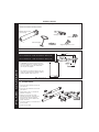
21 ROOF FLUE KIT CONTENTS / OPTIONS
H
J
B. Flue seal collar
C. 3,5x13 screw
D. Pitched roof tile/flat roof tile
weather collar
E. Vertical connector (60/100)
F. Retention flange/screw
G
G. Adaptor (60/100 to 80/125)
I.
90o elbow kit (80/125)
A
E
D
o
J. 45 elbow kit (80/125)
FLUE
H. Roof flue extension duct kit
(80/125)
F
C
B
ix7467
Note. Items D, E, G, H, I and J are not supplied with the roof flue kit.
excel HE - Installation and Servicing
19
INSTALLATION
22 FLUE TERMINAL POSITION
The terminal should be positioned so that products of
combustion can safely disperse at all times.
Pluming may occur at the termination so, where
possible, terminal positions where this could cause
a nuisance should be avoided.
*
Minimum dimensions are shown below
ex8389
610 mm
min.
610 mm
min.
FLUE
OUTLET
ex7531
*Flat Roof - 600mm
Terminal Position
Minimum Dimension
Directly below an opening,
air brick, windows, etc.
300 mm
Below plastic / painted gutters
300 mm
Painted surface
300 mm
Below eaves or balcony
500 mm
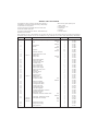
23 FLUE ARRANGEMENT
80/125
Quantity
C24 C28 C32
Part No. Description
n/a
Maximum Flue Length
(m) 16
12
8
201 548 Flue ext. 80/125
15
11
7
201 547 Terminal Vertical Roof 80/125
1
1
1
158 431 Weather Collar Pitched Roof
1
1
1
158 432 Weather Collar Flat Roof
1
1
1
201 550 90 Elbow kit (80/125)
4
4
4
201 551 45o Elbow kit (80/125)
4
4
4
201 184 Vertical Connector
1
1
1
201 549 Adaptor (60/100 - 80/125)
1
1
1
o
Note.
The equivalent flue length resistance of the 90 o elbow kit
(80/125) is 1.5m and the 45o elbow kit (80/125) is 1.0m.
20
excel HE - Installation and Servicing
INSTALLATION
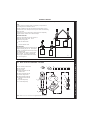
24 ASSEMBLING THE ROOF FLUE KIT
Determine the correct height that the flue should terminate
above the roof. If after calculating or measuring the overall flue
height from the top of the boiler, it is necessary to cut both
pipes of assembly A, then ensure they are cut equally leaving
the inner flue tube longer than the outer air tube as supplied.
(Refer to No. 6 below)
max 41
o
min 16
o
1
MAX LENGTH:
C24 - 16 m
C28 - 12 m
C32 - 8 m
Ensure the cut pipe ends are free from any burrs.
1. Ensure the flue seal collar B is located onto the flue
assembly A.
A
B
7469
2. Position the roof flashing plate D (supplied separately) over
the hole cut in the roof and insert flue assembly A from the
roof end.
7468
3. Push fit the vertical connector E (supplied seperately) into the
boiler flue connection and retain with the retention flange F
(supplied with the boiler) and securing screw. ENSURING
THE GASKETS IN THE BOILER FLUE OUTLET ARE
CORRECTLY FITTED.
2
4. "Push" fit the 60/100 to 80/125 adaptor G (supplied
separately) into the vertical connector.
A
5. "Push" fit extension duct H (if required (supplied separately))
and the roof flue kit assembly A into the adaptor G.
A
6. If the last extension duct requires cutting, measure the
distance (outer ducts) between the duct and the
terminal and add 100 mm to this dimension. This
gives the length of the last extension duct.
4
G
D
E
F
D
Ø
7. Slide down and position the flue seal collar B
over the roof plate D and secure it with the 3
screws C to the flue assembly A.
Ø
OUTLET
Note. Check the position of the inner flue duct relative
to the outer duct on the assembled extension duct(s)
and ensure the terminal flue duct is cut longer than the
air duct to ensure engagement in the final flue duct
seal.
7470
60
100
8. Finally ensure the roof flashing plate D is
correctly sealed to the roof.
3
H
5
G
ix7472
A
A
C
C
6
B
B
D
ix7473
excel HE - Installation and Servicing
FLUE
ex7533
6
ix7474
21
INSTALLATION
25 FITTING THE OPTIONAL FLUE FINISHING KIT
Contents:
Outer wall sealing plate - 1off
Inner rubber wall seal (White) - 1 off
Outer rubber wall seal (black) - 1 off
Wall plugs - 4 off
Screws No. 10x2" - 4 off
1. Fit black outer wall seal over terminal and
ensure the retaining rim is located in the
terminal depression.
2. Fit flue pipe assembly through the hole
previously cut in wall.
3. Fit white inner wall seal and push up to
inner wall.
4. Fit turret to boiler (see Frame 30) and to
the flue pipe assembly.
1
5. Fit outer wall sealing plate over outer wall
seal and retain with the 4 screws and wall
plugs provided.
3
5
FLUE
OUTLET
4
ix7475
22
excel HE - Installation and Servicing
INSTALLATION
INSTALLATION
26 FITTING THE WALL MOUNTING PLATE
Fit the wall mounting plate either:
a.
Directly to the wall
Insert wall plugs.
Hang the frame onto the screws (take care to use the
same hole position from each group as previously
chosen with the wall template) and tighten up.
ix7428
Put the screws into the wall plugs and leave 10mm
proud
or
Wall plug
b. If using optional Stand-Off Frame or Pre-Piping Frame,
refer to instructions provided with kit.
Screw
(10mm proud)
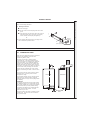
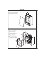
27 CONDENSATE DRAIN
Refer also to the British Gas document: 'Guidance
Notes for the Installation of Domestic Gas
Condensing Boilers' (1989).
The boiler comes with an integral 100mm
condensate trap. The boiler condensate drain
must be connected to a drainage point, preferably
within the building. This condensate drainage
should be run in standard 21.5mm overflow pipe.
Before fitting drain pipe remove plastic plug from
connection. Connection to the boiler is by push fit
into the rubber collar protruding from the boiler.
Ensure that the condensate trap is full of water
before commissioning the boiler . Refer to Frame
30.
The routing of the drain must be made to allow a
minimum fall of 1 in 20 away from the boiler,
throughout its length.
Front View
Side View
The drainage pipework must be arranged so that
obstruction (e.g. through freezing) of external
drainage pipe does not give rise to spillage within
the dwelling.
All pipework and fittings in the condensate drain
system must be made of plastic. No other
materials may be used.
The drain outlet on the boiler is standard 21.5mm
overflow pipe. This size must not be reduced in
any part of its length.
excel HE - Installation and Servicing
ix77413
IMPORTANT.
If excessive external pipework cannot be avoided
an additional siphon kit or a condensate removal
pump (both available as an option) and insulation
are recommended to prevent possible freezing.
25 mm
Condensate
drain
23
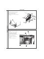
28 MOUNTING THE BOILER
Note. The boiler may require two men to lift it onto the wall
mounting plate.
1. Lift the boiler by the packaging base onto the plate,
locating it over the tabs at the top of the bracket. Ensure
the boiler is correctly retained on the wall mounting plate
tabs. Remove packaging base.
Note. If side clearance is limited, the packaging base can
be removed prior to lifting.
2. Ensure the plastic plugs are removed from both the CH
and DHW Connections. N.B. Some spillage of water may
occur from the connections when mounting the boiler onto
the wall plate.
3. Fit the two 22mm CH isolating ball valves to the two
CH connections on the boiler using the two 22mm
washers provided.
3
4. Fit the 15mm isolating ball valve to the DHW inlet
connection on the boiler using the 12mm washer
provided.
5. Fit the 15mm bulkhead elbow to the DHW outlet
CH
flow
connection on the boiler using the 12mm washer
provided.
6. Fit the 15mm gas cock to the gas connection on the
boiler using the gas cock seal provided.
ix7431
5
DHW
Outlet
3
6
Gas
DHW
Inlet
4
ix7443
CH
return
29 CONNECTIONS - CH, DHW AND GAS
Notes.
1. Central Heating
For heating loads in excess of 60,000 Btu/h use 28mm x
22mm connectors to connect the boiler flow and return
pipes to 28mm system pipework.
2. Central Heating, Domestic Hot Water and Gas
Do not subject any of the isolating valves to heat as the
seals may be damaged.
3. Gas
Refer to Frame 2 for details of the gas connection position.
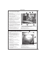
30 CONNECTING THE FLUE TO THE BOILER
Note.
Before fitting the flue turret fill the condensate trap or siphon trap
within the boiler by pouring a cupful of water into the flue outlet A.
Take care to ensure that the water is only poured into the flue
outlet, and does not spill into the boiler casing.
2
IMPORTANT. DO NOT fit flue restrictor if flue length is
greater than 775 mm ('B' Pack).
3
1. "Push" fit the flue restrictor (if necessary) into centre of plastic flue
outlet. Refer to Frame 12.
2. Insert the flue assembly through the prepared hole in the wall.
3. Locate the flue turret on the top of the boiler. CHECK THAT THE FLUE
SEAL LOCATED IN THE TOP OF THE FLUE MANIFOLD IS SECURE
AND GIVING AN EFFECTIVE SEAL.
5
4
Flue
1 Restrictor
A
4. Locate the flue into the turret and push to ensure full engagement.
5. Secure the flue turret on top of the boiler by inserting the open
ends of the turret clamp under the 2 studs and fixing it in the
middle with the single M5 x 10mm pozi-hex screw provided.
6. Flues over 1 metre long.
ex7953
INSTALLATION
INSTALLATION
Fix the flue support bracket to the wall, using the 2 wall plugs and
wood screws.
24
excel HE - Installation and Servicing
INSTALLATION
INSTALLATION
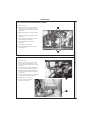
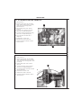
31 PRESSURE RELIEF VALVE DRAIN PIPE
The pressure relief valve is located at the bottom
LHS of the boiler.
Remove front panel. See Frame 44.
The pressure relief pipe (to be
found in the hardware pack) must
be fitted to the pressure relief valve
and sealed with the olive and back
nut provided. Ensure the pipe is
extended so that the discharge of
water or steam cannot create a
hazard to the occupants of the
premises or damage the electrical
components and wiring.
Pressure
relief pipe
Nut
ix7447
Olive
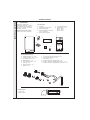
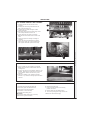
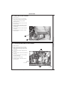
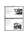
32 FILLING
Central Heating
1. Remove the front, RH side and bottom cover
panels. See Frames 44, 45 and 46.
2. Ensure the CH isolating valves are open.
3. Open the stopcock at the filling point connection
to the CH system until water is heard to flow.
4. Open each radiator vent starting at the lowest
point of the system and fully fill and vent the
system.
5. Bleed air from the pump and ensure it is free to
rotate.
A. Remove the pump vent plug
B. Using a screwdriver, rotate the shaft
several times
5A
C. Replace the pump vent plug.
Note. Some slight water leakage will occur.
Ensure control box wiring is protected.
6. Ensure the pressure indicated on the pressure
gauge is between 1 and 1.5 bar.
ix7435
Domestic Hot Water
1. Close all hot water draw off taps.
2. Open the cold water inlet valve.
3. Slowly open each draw off tap and close only
when clear and air bubble free water flows out.
excel HE - Installation and Servicing
25
INSTALLATION
INSTALLATION
33 ELECTRICAL CONNECTIONS
WARNING. This appliance MUST be earthed.
For Ireland reference should be made to the current ETCI
rules for electrical installations.
A mains supply of 230 V ~ 50 Hz is required.
Mains wiring should be 3 core PVC insulated flexible cord
NOT LESS than 0.75mm2 (24x0.2mm) and to BS. 6500, Table
16. (0.5mm2 flex is not acceptable - for mechanical, not
electrical reasons.)
The supply connection is intended to be made via a double
pole switch having a 3mm (1/8") contact separation in both
poles, serving only the boiler and system controls.
The fuse rating should be 3A.
Mains wiring external to the boiler MUST be in accordance
with the current I.E.E. (BS7671) Wiring Regulations and any
local regulations.
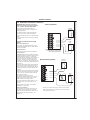
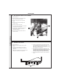
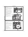
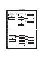
34 INTERNAL WIRING
INCOMING MAINS WIRING DETAIL
1
To gain access to the power supply and external controls
terminal block:
1. Remove the screws and the cover panel.
2. Remove the control box fixing screws.
3. Pull the control panel forward.
4. Remove the screws and the service panel.
Service
panel
2
ix7424
4
ex7787
L
3
Mains
N
LEGEND
L
N
F1
F2
Link
R1
R2
ix7421
F1
F2
R1
R2
R3
Live
Neutral
Earth
Frost Stat Switched Live
Frost Live Feed
Room Stat Switched Live
Room Live Feed
Programmer Common SWL
R3
Note. Ensure that the lengths of the current conductors are shorter than the earth conductor so that if the cable slips in its
anchorage the current carrying conductors become taut before the earth conductor.
26
excel HE - Installation and Servicing
INSTALLATION
WARNING. When the boiler is powered
'ON' mains voltage is present on terminals
"F2" and "R2". PLEASE TAKE CARE.
INSTALLATION
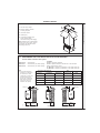
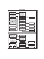
35 EXTERNAL ELECTRICAL CONTROLS
A No Programmer
Optional
Frost Stat
Wiring external to the boiler MUST be in
accordance with the current I.E.E. (BS. 7671)
Wiring Regulations.
For Ireland reference should be made to the
current ETCI rules for electrical installation.
L
The controls internal fuse is a 2A fast blow 250V
rated.
N
Lock the flexible cords in place with the clamps
provided.
F1
ELECTRICAL CONNECTIONS FOR A COMBI
BOILER
F2
Optional Programmer Kit
R1
Room
Stat
R2
ex9042
An optional 7 day digital programmer or 24hr
mechanical programmer kit is available with its
relevant instructions.
R3
R2 and R3 connections are used for
the room stat when in conjunction
with integral programmer kit.
Room Thermostat
This should be wired as shown in diagram A.
Frost Protection
excel HE appliances are provided with a built in
anti-freeze system that operates the boiler when
o
the temperature is below 5 C. Internal frost
protection operates regardless of the position of
the main switch and CH heating thermostat
knob (B). Therefore, when the boiler is not lit
and used in cold weather, with consequent risk
of freezing, the supply to the boiler should be left
switched on.
B External Programmer
Central heating systems fitted wholly inside the
house do not normally require frost protection
as the house acts as a 'storage heater' and can
normally be left at least 24 hours without frost
damage.
L
N
However, if parts of the pipework run outside the
house or if the boiler will be left off for more than
a day or so then a frost thermostat should be
wired into the system.
The frost thermostat should be sited in a cold
place but where it can sense heat from the
system.
F1
F2
Room
Stat
R1
R2
ix7423
To maintain frost protection with the
programmer selector switches set to OFF, the
mains supply and the boiler panel controls
MUST be left in the running position.
Optional
Frost Stat
R3
External
Programmer
Wiring should be as shown, with minimal
disturbance to other wiring.
External Programmers
Earths are not shown for clarity but must never be omitted.
This should be of the single channel type (as
this boiler does not incorporate a pre-heat
facility for the instantaneous hot water service).
Note. These diagrams are schematic only and do not show
external terminal strips etc.
Programmers with room thermostat - see
diagram B.
excel HE - Installation and Servicing
27
INSTALLATION
b
br
r
gr
gr
g/y
1
1
v
v
1
2
3
r
2
4 678
2
r
Ignitor/Gas Valve I/F
1
1
w
w
1
1
2
or
8
1 345
6
7
pk
bk
1
y
y
SIT Sigma
845 Gas Valve
1 2
b
2
3
b
or
1
2
3
2
br
bk
b
1
DHW
Flow Switch
AC Pump
g/y b br
Chassis
Earth
r
v
- red
- violet
NAC
Lead
br
b
r
w
bk
1
35
246
1 2 3 4 5 6 7
g/y
48
12 13 14 15 16
b
8
9 10 11
54 55 56
g/y
g/y
17
18
19
w w
25
26
27
28
PCB1
BIC 580
29
30
31
32
33
34
35
36
37
38
39
40
41
42
43
44 45 46 47
bk
bk
bk
L N E F1 F2 R1 R2 R3
w w
20
21
22
23
24
gr gr or or r
Terminal
Strip
bk
pk
v
v
y
y
b
b
r
Controls
Earth
w
w
9 10 11 12
bk
bk
bk
bk
6 7 8
12345
w
w
1 2 3 4 5 6 7 8
br
r
br
20 21 22
17 18 19
13 14 15 16
r b
w
w
PCB2
Exp.
Board
br
1 2
w br
bk
r
Switch,
SPST
bk
ex8420
g/y - green/yellow
excel HE - Installation and Servicing
bk
r
br
g/y
49 50 51 52 53
w - white
y - yellow
b
br
b
br
bk
br
b
INSTALLATION
or - orange
pk - pink
g/y
2
NAC1
1
2
Pump Proving
Switch
Divertor Valve
Burner
Earth
DHW
Flow
Thermistor
Overheat
Stat
Condensate
Blockage
Thermistor
br - brown
gr - grey
g/y
Ignition
Electrode
Ignition
Electrode
Flow
Thermistor
3 Earth
1
2 3
2
Detection
Electrode
In-line Spade
C
NC NO
36 PICTORIAL WIRING DIAGRAM
1
Fan 1
AC Fan, Single speed
1
Air
Pressure
Switch
LEGEND
b - blue
bk - black
28
Interference
suppressor
37 FUNCTIONAL FLOW WIRING DIAGRAM
gr
or
pk
r
LEGEND
b - blue
bk - black
br - brown
Flow Thermistor
-
grey
orange
pink
red
v w y g/y -
violet
white
yellow
green/yellow
Ignition
Ignition
Electrode Electrode
DHW Thermistor
Divertor Valve
Overheat
Stat
AC Pump
1
1
1
2
1
r r
or
2
br
2
2
bk
3
br
b
b
1
2
3
g/y
or
b b
Detection
Electrode
1
1
Ignitor/Gas Valve I/F
2
Pump Proving Switch
BIC 580
r
r
Flow
Flow
b
b
DHW Temperature
DHW Temperature
2
1
y y
v
v
PPS
PPS
y
y
DHW Flow
DHW Flow
In line spade
1
1
2
Burner
Earth
Ionisation
g/y
g/y
Chassis
Earth
g/y
Controls
Earth
g/y
bk
r
w
b
br
Terminal
Strip
1
2
3
4
5
6
7
8
Burner PE
Chassis PE
Supply Earth
R2 - SWL
R1/F1 - Live feed
F2 - Frost SWL
Supply Neutral
Supply Live
DV Live 1
DV Live 2
DV Neutral
br
b
bk
Pump Live
Pump Neutral
Pump Earth
br
b
g/y
Mod+
Mod-
pk
bk
GV + IGN Live
IGN Neutral
GV Neutral
GV Neutral
GV Earth
b
br
r
bk
g/y
APS
APS
Fan Neutral
Fan Earth
Fan Live
0V
Analog input
24V
5V
Air
Pressure
Swirch
pk
6
1
345
8
bk
7
C
SIT Sigma 845 Gas Valve
1
gr
b
g/y
w
w
w
w
NC NO
2
3
gr
br
Fan live in
Fan live 1
0V Fan live 2
Analogue out
24V
Fume 1
5V
Fume 2
br
r
Fan2
AC Fan, Single speed
Expansion Board
w
w
w
w
2
3
1
gr
gr
Control 0 1 2 3
br
678
2 1
OH
OH
lead
DHW Flow Switch
or
or
1
v v
642
5 3 NAC
2
1
4
b
1
r
2
br
3
1
Switch, SPST
bk bk bk bk
Condensate Blockage
Thermistor
Earth
g/y
Interference
suppressor
ex7463
38 COMMISSIONING AND TESTING
A. Electrical Installation
1. Checks to ensure electrical safety should be carried out by a competent person.
2. ALWAYS carry out the preliminary electrical system checks, i.e. earth continuity, polarity, resistance to earth and short circuit,
using a suitable test meter.
B. Gas Installation
1. The whole of the gas installation, including the meter, should be inspected and tested for soundness and purged in
accordance with the recommendations of BS. 6891.
In IE refer to IS.813:2002.
2. Purge air from the gas installation by the approved methods only.
C. Flue Sealing
1. Check the integrity of the flue outlet and air inlet system to the boiler ensuring no leaks are evident from piping joints or flue/air
sampling points.
WARNING. Whilst effecting the required gas soundness test and purging air from the gas installation,
open all windows and doors, extinguish naked lights and DO NOT SMOKE.
excel HE - Installation and Servicing
29
INSTALLATION
INSTALLATION
39 INITIAL LIGHTING
Winter
E
C
D
B
A
if77434
1
2
3
F
Summer
LEGEND
A. Boiler On/Off switch.
B. Main switch & CH thermostat knob.
C. DHW thermostat knob
D. Pressure gauge
E. Operational lights (1 & 3) / Fault
indication light (2)
F. Optional programmer
G
Condensate
Drain
Condensate drain
Automatic air vent
Burner pressure test point
CH max. pressure
adjustment nut
L. DHW min. pressure
adjustment screw
M.
N.
P.
R.
S.
T.
U.
G.
H.
J.
K.
Gas inlet pressure test point
CH return isolating valve
DHW inlet isolating valve
Gas service cock
DHW flow
CH flow isolating valve
Gas valve electrical connectors
Gas Valve
M
L
K
H
U
J
ix7436
INSTALLATION
INSTALLATION
S
1. Check that the system has been filled and that the boiler is
not airlocked. Ensure the automatic air vent cap (H) is
open.
T
R
P
N
10. Switch the electricity supply ON and check all external
controls are calling for heat.
Note.
It is important the burner is not operated before the system is
11. CENTRAL HEATING
fully vented of air. If it is necessary to operate the appliance
Set the main switch and CH thermostat knob (B) to
pump to assist venting of the air this must be done with the gas
position shown in diagram and switch the boiler on/off
service cock turned off.
switch (A) to ON. The boiler control should now go through
its ignition sequence until the burner is established.
2. Refit the boiler RHS panel. Refer to Frame 45.
Green operational light 1 (E) will be illuminated when
3. Replace control panel and secure with fixing screws.
burner is lit.
4. Check that all the drain cocks are closed and that the CH
and DHW isolating valves (T, P and N) are OPEN.
5. Check that the electrical supply is OFF.
6. Check that the boiler on/off switch (A) is off.
7. Check that the gas service cock (R) is OPEN.
8. Slacken the screw in the inlet pressure test point (M) and
connect a gas pressure gauge via a flexible tube.
12. If the boiler fails to light up to five times during the ignition
sequence, the boiler will go to lockout and red operational
light 2 (E) will be illuminated. To reset the ignition
sequence turn the main switch (B) to '0' wait until the boiler
reaches standby state, indicated by no fan or pump
running (this can take up to 10 minutes in an overheat
condition). Turn the main switch (B) to the winter setting,
wait for 2 seconds then set the main switch (B) back to the
desired position.
9. Slacken the screw in the burner pressure test point (J) and
connect a gas pressure gauge via a flexible tube.
continued....................
30
excel HE - Installation and Servicing
40 INITIAL LIGHTING . . . . . CONTINUED
13. DOMESTIC HOT WATER
With the boiler firing, set the DHW thermostat knob (C) to
maximum and fully open a DHW tap. The boiler should
continue to run and provide hot water at the open tap.
Green operational lights 1 and 3 (E) will be illuminated
when burner is lit.
iii. If necessary, rotate the maximum gas pressure
brass hexagon nut adjustment (K) using a spanner
until you obtain the required pressure as indicated on
Table 2 (page 4) (burner pressure). By rotating
clockwise the pressure increases.
Minimum valve setting - DHW Only
14. Turn off the tap.
iv. Disconnect one of the two connectors (U).
15. Test for gas soundness around ALL boiler gas
components using leak detection fluid.
v.
16. Operate for 10 minutes to stabilise the burner temperature.
17. The boiler is preset at the factory to its maximum output.
Check the burner pressures against the values quoted in
Table 2 (page 4) by using the following procedure.
i.
Remove plastic protective cap from the mechanical
pressure adjustment components (L&K).
ii.
Start the boiler at its maximum power. Operate the
boiler in DHW mode or ensure that the boiler is not
range rated if the test is carried out in CH mode.
Maximum valve setting - CH & DHW
Note.
The minimum CH pressure is automatically set
electronically.
If necessary, rotate the minimum gas pressure
adjustment (red cross point screw) (L) until you
obtain the required pressure as indicated on Table 3
(page 4) (burner pressure). By rotating clockwise the
pressure increases.
vi. Turn the boiler off and re-connect the wire to the
modulating operator (U).
vii. Start the boiler and check again the maximum gas
pressure setting.
viii. Turn the boiler off and disconnect the inlet and burner
pressure gauges and close the gas valve inlet and
outlet pressure test points (J & M).
IMPORTANT.
After the gas pressure checks and any adjustment
operations, all of the test points must be sealed and leak
tested.
18. Refit the front panel and bottom panel.
41 GENERAL CHECKS
Make the following checks for correct operation:
checked at the gas meter, with no other appliance in use.
1. Hot water
If this check is not possible, ensure that the burner pressure
is:
a.
Fully open all DHW taps in turn and ensure that water
flows freely from them.
b.
Close all taps except the furthest one from the boiler
and check that the boiler is firing at maximum rate.
c.
Ensure that DHW temperature rise of approximately
40oC is obtained at the tap. This corresponds to a
flow rate of approximately:
8.4 (1.8) l/min (gpm) excel HE C24
10 (2.2) l/min (gpm)
excel HE C28
11.5 (2.6) l/min (gpm) excel HE C32
Note. Quoted flow rates and temperature rises are
those theoretically achievable. Flow rates measured
during commissioning may differ (due, for example, to
resistance of domestic hot water pipe lengths and
fittings or available dynamic gas pressures).
If necessary reduce the flow rate using isolation valve
'S'. Refer to Frame 39.
d.
Turn off the DHW tap.
2. Central heating
Operate each control separately and check that the main
burner or circulating pump, as the case may be, responds.
3. Gas rate
Check the boiler gas rate when the boiler is at full output.
The gas rate will normally be
45.8 (1.62) litres/min (ft3/min) for the model excel HE C24
13.4 (5.3) mbar (in. w.g.) for the model excel HE C24
10.5 (4.2) mbar (in. w.g.) for the model excel HE C28
12.9 (5.2) mbar (in. w.g.) for the model excel HE C32
In addition ensure the dynamic inlet pressure is 20mb.
4. Water circulation system. Refer to frame 6.
Note.
A suitable flushing solution should be used during
the flushing procedure.
a.
With the system HOT examine all water connections
for soundness.
b.
With the system still HOT, turn off the gas, water and
electricity supplies to the boiler and drain down, to
complete the flushing process.
c.
Refill the system, adding inhibitor (see 'Water
Treatment'), if required. Refer to Frame 10
d.
Balance the system. It is suggested that, initially, all
radiator handwheel valves (or TRVs if fitted) be set
fully open, that all lockshield valves be set a half-turn
open.
Make minor adjustments to each radiator to achieve the
same differential on all.
Finally, set the system controls to the users requirements.
If an optional programmer kit is fitted refer to the
instructions supplied.
53.5 (1.89) litres/min (ft3/min) for the model excel HE C28
62.1 (2.19) litres/min (ft3/min) for the model excel HE C32
excel HE - Installation and Servicing
31
INSTALLATION
INSTALLATION
SERVICING
42 HANDING OVER
After completing the installation and commissioning of the system the
installer should hand over to the householder by the following actions:
1. Hand the User Instructions to the householder and
explain his/her responsibilities under the relevant
national regulations.
6. Explain and demonstrate the function of time and
temperature controls, radiator valves etc., for the economic
use of the system.
2. Explain and demonstrate the lighting and shutting
down procedures.
7. If a programmer is fitted draw attention to the Programmer
Users Instructions and hand them to the householder.
3. The operation of the boiler and the use and adjustment
of all system controls should be fully explained to the
householder, to ensure the greatest possible fuel
economy consistent with the household requirements
of both heating and hot water consumption.
8. Loss of system water pressure
Advise the User of the precautions necessary to prevent
damage to the system and to the building, in the event
of the system remaining inoperative during frosty
conditions.
SERVICING
4. Explain the function and the use of the boiler heating
and domestic hot water controls.
Explain that due to system variations and seasonal
temperature fluctuations DHW flow rates/temperature
rise will vary, requiring adjustment at the draw off tap. It
is therefore necessary to draw the users attention to the
section in the Users Instructions titled “Control of Water
Temperature” and the following statement:
Explain that the dial on the boiler control panel indicates the
central heating system pressure and that if the normal COLD
pressure of the system is seen to decrease over a period of
time then a water leak is indicated. In this event a registered
local heating installer should be consulted.
WARNING.
Do not fire the boiler if the pressure has reduced to zero from
the original setting.
9. After installation and commissioning please complete the
commissioning Checklist before handover to
the customer. For IE it is necessary to complete a
“Declaration of Conformity” to indicate compliance to I.S.
813:2002
10. IMPORTANT
A comprehensive service should be carried out ANNUALLY.
“Additionally, the temperature can be controlled by
the user via the draw-off tap: the lower the rate the
higher the temperature, and vice versa”.
5. Explain the function of the boiler fault mode.
Emphasise that if a fault is indicated, the boiler should
be turned off and a CORGI registered local heating
installer consulted. In IE contact a competent person.
Stress the importance of regular servicing by a CORGI
registered installer. In IE servicing work must be carried out
by a competent person.
11. As the installer you may wish to undertake the service
contract yourself or alternatively offer to the customer the
benefits of the Ideal Care Scheme, details of which are
outlined in the householder pack supplied with this boiler.
43 SERVICING SCHEDULE
To ensure the continued safe and efficient operation of the
appliance it is recommended that it is checked at regular
intervals and serviced as necessary. The frequency of
servicing will depend upon the installation condition and
usage but should be carried out at least annually.
It is the law that any service work must be carried out by a
CORGI registered installer. In IE service work must be carried
out by a competent person.
1. Light the boiler and carry out a pre-service check, noting
any operational faults.
2. Check the gas consumption.
3. Connect a suitable gas analyser to the sampling point on
the top of the boiler or into the flue terminal if access is
possible (optional test).
For correct boiler operation, the CO/CO2 content of the flue
gas should not be greater than 0.004 ratio.
If this is the case, and the gas input is at least 90% of the
nominal, then no further action need be taken. If not,
proceed to Step 5.
4. Clean the main burner.
5. Clean the heat exchanger.
6. Check the condition of the combustion chamber insulation.
Any cracked or damaged pieces should be replaced.
32
7. Check the main injectors for blockage or damage.
8. Check that the flue terminal is unobstructed and that the
flue system is sealed correctly.
The servicing procedures are covered more fully in Frames
40 and 41 and MUST be carried out in sequence.
Note.
In order to carry out either servicing or replacement of
components the boiler front panel and sealing panel
must be removed. Refer to Frames 44 and 45.
WARNING. Always turn OFF the gas supply at the gas
service cock, and switch OFF and disconnect the electricity
supply to the appliance before servicing.
IMPORTANT.
9. After completing the servicing or exchange of components
always test for gas soundness and carry out functional
checks in 3 and 4 above.
10. When work is complete the sealing panel MUST be
correctly refitted, ensuring that a good seal is made.
Do NOT OPERATE the boiler if the sealing
panel is not fitted.
12. Complete the service section of the Benchmark
Commissioning Checklist.
excel HE - Installation and Servicing
SERVICING
44 BOILER FRONT PANEL REMOVAL
1
1. Remove the 2 fixing screws from the top
of the front panel.
SERVICING
ix7444
2. Lift the front panel upwards and forward
at the bottom to remove.
2
45 BOILER SIDE PANEL AND SEALING PANEL REMOVAL
1. Slacken the 2 top and 2 bottom
fixing screws from the LH and RH
side panels and remove the
panels.
1
2. To remove the sealing panel
remove the 4 fixing screws from the
front.
1
4
3. Remove the sealing panel by
pulling forward to disengage rear
clips.
4. Remove the fixing screws retaining
the inner sealing panel and remove
the panel taking care not to damage
the front insulation panel.
2
1
1
5
44
ix7
2
excel HE - Installation and Servicing
33
SERVICING
46 THE CONTROL BOX IN THE SERVICING POSITION
1. Remove the screws and the cover panel.
2. Remove the control box fixing screws.
1
3. Pull the control panel forward.
4. Remove the control box lid fixing screws and
remove lid.
2
4
SERVICING
ix7424
ix7426
3
47 FAN AND VENTURI REMOVAL AND CLEANING
1. Remove the screw on the fan mounting
bracket.
2
2. Carefully pull fan from the recuperator
sealing gasket. Check the gasket for
damage and replace if necessary.
3
3. Disconnect the electrical leads from the
fan.
4. Disconnect APS sensing tube.
5. Inspect venturi and fan and clean as
necessary.
6. Reassemble in reverse order.
1
4
34
excel HE - Installation and Servicing
SERVICING
48 BURNER REMOVAL AND CLEANING
1. Carefully separate the detection lead in-line
connector.
3
2. Carefully pull off the two ignition leads from the
side of the PCB ignition unit.
3. Carefully pull the 3 leads through the rubber
sealing grommets.
1
4. Remove the earth lead and 4 burner fixing screws
and carefully withdraw the burner unit.
5. Inspect the burner and clean as necessary.
Note. Brushes with metallic bristles should not be
used.
2
6. Inspect all injectors for blockage or damage if
necessary.
7. Inspect the three electrodes/leads for damage
and check the spark gap is 3-5mm between the
pair of ignition electrodes (centre and RH side).
7
SERVICING
3-5mm
4
49 CLEANING THE HEAT EXCHANGER
1. Using a suitable tool as supplied in the standard
British Gas Flue brush kit, clean between the heat
exchanger fins.
2. Access to the base of the combustion chamber is now
possible. Brush clean any deposits from the base of
the combustion chamber and remove any loose
deposits.
3. Check the condition of the combustion chamber
insulation. Any cracked or damaged pieces should be
replaced.
50 RE-ASSEMBLY
1. Refit the burner assembly and earth tab.
6. Refit the control box cover.
2. Reconnect ignition and detection leads.
3. Reconnect the fan electrical leads.
7. Push the control box back into its working
position and secure.
4. Refit the fan / venturi assembly.
8. Refit the boiler front and bottom panels.
5. Refit the boiler sealing panel.
9. Turn on the gas supply at the gas service cock.
IMPORTANT
Ensure that the boiler sealing panel is correctly
fitted and that a good seal is made.
10. Reconnect the electrical supply.
excel HE - Installation and Servicing
35
SERVICING
51 REPLACEMENT OF COMPONENTS
GENERAL
IMPORTANT.
When work is complete, the sealing panel, if removed, must
be correctly refitted - ensuring that a good seal is made.
When replacing ANY component
1. Isolate the electricity supply.
Notes.
1. In order to assist fault finding, the control panel has an
LED diagnostic display. The key to boiler fault conditions
is shown in Frame 79.
2. Turn off the gas supply.
3. Remove the boiler front panel. Refer to Frame 38.
After replacing ANY component check operation of the boiler,
including gas soundness, gas rate and combustion test.
2. In order to replace components in Frames 68-78 it is
necessary to drain the boiler. Refer to Frame 67.
THE BOILER MUST NOT BE OPERATED WITHOUT THE SEALING PANEL FITTED
52 CONDENSATE BLOCKAGE THERMISTOR REPLACEMENT
1. Refer to Frame 51.
4
2. Remove the boiler front, side and sealing
panels. Refer to Frame 44 and 45.
3. Carefully pull off the green electrical
connection.
SERVICING
4. Unscrew the condensate blockage
thermistor.
5. Fit new condensate blockage thermistor
complete with new washer.
6. Re-assemble in reverse order.
7. Check the operation of the boiler. Refer to
Frame 50 and 51.
3
53 FAN AND FAN SUPPRESSOR REPLACEMENT
5,7
4
FAN
1. Refer to Frame 51.
2. Remove the boiler front, side and sealing
panels. Refer to Frame 44 and 45.
3. Remove the fan mounting fixing screw.
4. Pull fan from the recuperator sealing gasket.
5. Disconnect electrical leads from the fan.
6. Pull plastic sensing pipe from venturi
connection.
7. Reconnect the fan electrical connections and
fit the new fan in reverse order ensuring the
plastic venturi pipe is replaced.
8. Re-assemble the boiler in reverse order.
9. Check the operation of the boiler. Refer to
Frame 50 and 51.
Fan Suppressor
1. As 1-5 above.
2. Pull off fan suppressor.
36
3
6,7
excel HE - Installation and Servicing
SERVICING
54 BURNER INJECTOR REPLACEMENT
5
1. Refer to Frame 51.
2. Remove the boiler front, side and sealing panels. Refer to
Frames 44 and 45. Put the control box into the servicing
position. Refer to Frame 46.
3
3. Carefully separate the in-line connector from the detection lead.
4. Carefully pull off the two ignition leads from the side of the
ignition unit.
5. Carefully pull the three leads through the rubber sealing
grommets.
6. Remove the earth lead and the four burner fixing screws and
carefully withdraw the burner unit.
4
7. Unscrew each injector from the manifold.
Injectors
8. Fit new injectors using new
copper washers provided.
9. Re-assemble in reverse
order.
10. Check the operation of the
boiler. Refer to Frame 50
and 51.
55 BURNER REPLACEMENT
1. Refer to Frame 51.
2. Remove the boiler front, side and sealing panels. Refer
to Frames 44 and 45. Put the control box into the
servicing position. Refer to Frame 46.
3. Carefully separate the in-line connector from the detection
lead.
4. Carefully pull off the two ignition leads from the side of
the ignition unit.
5. Carefully pull the three leads through the rubber sealing
grommets.
6. Remove the earth lead and the four burner fixing screws
and carefully withdraw the burner unit
7. Fit the new burner unit.
8. Re-assemble in reverse order.
9. Check the operation of the boiler. Refer to Frame 50 and 51.
5
3
6
4
56 OVERHEAT THERMOSTAT REPLACEMENT
1. Refer to Frame 51.
2. Remove the boiler front, side and sealing panels. Refer to Frames 44
and 45.
3. Overheat Thermostat:
a. Carefully pull off the 2 electrical connections.
b. Unclip thermostat from pipe.
c. Fit 2 electrical connections onto new thermostat
d. Clip new thermostat onto pipe ensuring correct positioning on heat
exchanger manifold and re-assemble in reverse order.
4. UNDER NO CIRCUMSTANCES REFIT THE OVERHEAT THERMOSTAT
ONTO THE COLD RECUPERATOR RETURN PIPE.
5. Check the operation of the boiler. Refer to Frame 50 and 51.
excel HE - Installation and Servicing
3a
4
3d
3b
37
SERVICING
6
7
SERVICING
57 IGNITION ELECTRODE REPLACEMENT
1. Refer to Frame 51.
2. Remove the boiler front, side and
sealing panels. Refer to Frames 44 and
45. Put the control box into the servicing
position. Refer to Frame 46.
5
3. Carefully separate the in-line connector
from the detection lead.
3
4. Carefully pull off the two ignition leads
from the side of the ignition unit.
5. Carefully pull the three leads through the
rubber sealing grommets.
4
6. Remove the earth lead and the four
burner fixing screws and carefully
withdraw the burner unit.
7
7. Remove the fixing screws
from the centre and RH
electrodes and carefully
withdraw the two ignition
electrodes.
SERVICING
8. Fit new ignition electrodes.
9. Re-assemble in reverse
order.
10. Check the operation of the
boiler. Refer to Frame 50
and 51.
6
58 FLAME DETECTION ELECTRODE REPLACEMENT
1. Refer to Frame 51.
2. Remove the boiler front, side and sealing
panels. Refer to Frames 44 and 45. Put the
control box into the servicing position. Refer
to Frame 46.
5
3. Carefully separate the in-line connector from
the detection lead.
3
4. Carefully pull off the two ignition leads from
the side of the ignition unit.
5. Carefully pull the three leads through the
rubber sealing grommets.
6. Remove the earth lead and the four burner
fixing screws and carefully withdraw the
burner unit.
4
7
7. Remove the fixing screw
from the LH electrode and
carefully withdraw the
detection electrode.
8. Fit new detection electrode.
9. Re-assemble in reverse
order.
10. Check the operation of the
boiler. Refer to Frame 50
and 51.
38
6
excel HE - Installation and Servicing
SERVICING
59 SPARK GENERATOR REPLACEMENT
4
5
3
1. Refer to Frame 51.
2. Remove the boiler front and side panels. Refer to Frame 44
and 45 and put the control box into the servicing position.
Refer to Frame 46.
3. Carefully pull off the two ignition leads from the side of the
ignition unit.
4. Remove the electrical plug from the printed circuit board.
5. Carefully pull the spark generator forward to disengage the
4 pin connection at the top of the gas control.
6. Fit the new spark generator and re-assemble in reverse
order.
7. Check the operation of the boiler. Refer to Frame 50 and 51.
60 GAS CONTROL VALVE REPLACEMENT
6
SERVICING
1. Refer to Frame 51.
2. Remove the boiler front and side
panels. Refer to Frame 44 and 45 and
put the control box into the servicing
position. Refer to Frame 46.
3. Remove the spark generator. See Frame
59.
4. Pull the two electrical connections from
the gas control valve.
5. Undo the gas inlet pipe union at the gas
service cock.
6. Undo the union nut on the outlet of the
gas control valve.
7. Remove the 2 gas control valve bracket
fixing screws.
8. Withdraw the valve complete with
bracket, inlet and outlet pipes.
9. Transfer the bracket, inlet pipe and
outlet pipe to the new gas control valve.
10. Fit the new gas control valve , taking
care not to trap wiring harness between
bracket and chassis, ensuring that any
seals showing signs of damage or
deterioration are replaced.
11. Re-fit spark generator and fully reassemble in reverse order.
12. Check the operation of the boiler , refer
to Frame 50 and 51, ensuring the gas
pressure is correctly set. See Frame 39
and 40
7
4
5
61 DIVERTER VALVE ACTUATOR REPLACEMENT
3
1. Refer to Frame 51.
2. Remove the boiler front and side panels. Refer to Frame 44 and 45 and
put the control box into the servicing position. Refer to Frame 46.
3. Loosen retention clip with screw driver and pull the clip from the diverter
valve.
Blue
4. Remove the three electrical connections noting their position.
Black
5. Carefully remove the actuator.
6. Fit new actuator and re-assemble in reverse order ensuring the 3 wires
are correctly replaced as shown.
7. Check the operation of the boiler. Refer to Frame 50 and 51.
excel HE - Installation and Servicing
Brown
4
39
SERVICING
62 COMBUSTION CHAMBER INSULATION REPLACEMENT
1. Refer to Frame 51.
2. Remove burner assembly. Refer to
Frame 55.
3. Remove the two screws retaining both
left and right hand combustion chamber
side panels.
4. Slide the combustion chamber side
panel insulation from its retention and fit
new insulation panels.
5. Lift rear insulation panel from its
retention and replace with new panel.
3
6. Remove the front panel insulation
(straighten 2 top retaining clips and lift
from bottom retention return) and replace
with new panel.
7. Reassemble in reverse order.
SERVICING
8. Check the operation of the boiler. Refer
to Frame 50 and 51.
4
5
63 PCB REPLACEMENT (MAIN PCB AND EXPANSION PCB)
Note. Antistatic precautions must be observed when
handling the main or expansion PCB.
1. Refer to Frame 51.
2. Remove the boiler front, side and sealing panels. Refer to
frame 44 and 45. Put the control box into the servicing
position. Refer to Frame 46.
3. Carefully remove all push on connectors and earth
connections (main PCB only) from the printed circuit board.
4. Remove the PCB from the five plastic supports (main PCB)
or two plastic supports (expansion PCB).
5. Fit new PCB and refit all push on connectors and earth
connections.
6. Reassemble in reverse order.
7. Check the operation of the boiler. Refer to Frame 56 and 51.
4
40
excel HE - Installation and Servicing
SERVICING
64 MAINS SWITCH REPLACEMENT
1. Refer to Frame 51.
2. Remove the boiler front, side and sealing
panels. Refer to Frame 44 and 45. Put the
control box into the servicing position.
Refer to Frame 46.
3. Remove the two electrical connections from
the mains switch.
4. Depress the plastic side retention clips and
remove the mains switch from the front of
the control box.
5. Fit new mains switch and replace electrical
connections.
6. Check the operation of the boiler. Refer to
Frame 50 and 51.
SERVICING
3
4
65 CH AND DHW MICROSWITCH REPLACEMENT
1. Refer to Frame 51.
2. Remove the boiler front, side and sealing
panels. Refer to Frame 44 and 45. Put the
control box into the servicing position. Refer
to Frame 46.
4
3. Pull microswitch forward to disconnect from
diaphragm.
4. Lift plastic retention clip and remove electrical
connection.
5. Fit electrical connection to new microswitch
and refit to diaphragm.
6. Re-assemble in reverse order.
7. Check the operation of the boiler. Refer to
Frame 50 and 51.
CH
microswitch
3
excel HE - Installation and Servicing
DHW
microswitch
41
SERVICING
66 AIR PRESSURE SWITCH REPLACEMENT
1. Refer to Frame 51.
2. Remove the boiler front and left hand side
panel. Refer to Frame 44 and 45.
3. Remove sensing pipe from air pressure
switch.
4. Remove the two screws retaining the air
pressure switch.
5. Remove electrical connections.
5
6. Fit new air pressure switch and refit electrical
connections and sensing pipe.
7. Re-assemble in reverse order, ensuring the
sensing pipe is replaced onto the top
connection marked "L".
4
3
67 DRAINING THE BOILER
1. Refer to Frame 51.
4. As there is no direct drain for the domestic hot water
circuit, depending on the location of the boiler, opening
the lowest hot water tap may drain this circuit.
2. Close all the water isolating valves (CH and
DHW).
Note. Some residual water may be experienced during
the replacement of components.
3. To drain the central heating circuit, attach a
length of hose to the drain point and open the
drain valve.
5. After replacing any component on the boiler, close
the drain valve, remove the hose and open all system
isolating valves (re-pressurise as appropriate)
before proceeding to check operation of the boiler.
Note. Some residual water may be experienced
during the replacement of components.
6. Check the operation of the boiler. Refer to Frame 50
and 51.
ix7442
SERVICING
8. Check the operation of the boiler. Refer to
Frame 50 and 51.
3
2
42
excel HE - Installation and Servicing
SERVICING
68 CH AND DHW DIAPHRAGM REPLACEMENT
1. Refer to Frame 51.
2. Remove the boiler front, side and sealing
panels. Refer to Frame 44 and 45. Put the
control box into the servicing position. Refer
to Frame 46.
4
3. Drain the boiler water circuit. Refer to Frame
67.
4. Pull microswitch forward to disconnect from
diaphragm.
5. Using a suitable tool, remove the four torx
screws retaining the diaphragm.
6. Fit the new diaphragm and refit the
microswitch.
7. Re-assemble in reverse order.
8. Check the operation of the boiler. Refer to
Frame 50 and 51.
SERVICING
5
69 PRESSURE GAUGE REPLACEMENT
1. Refer to Frame 51.
2. Remove the boiler front, side and sealing
panels. Refer to Frame 44 and 45. Put the
control box into the servicing position. Refer
to Frame 46.
3. Unscrew the pressure gauge sensing pipe
retaining nut from the pressure relief valve.
4. Remove the pressure gauge head from the
control panel front by depressing the plastic
retention clips.
5. Fit the new pressure gauge and reconnect the
sensing head to the pressure relief valve.
6. Re-assemble in reverse order.
3
7. Check the operation of the boiler.
Refer to Frame 50 and 51.
4
excel HE - Installation and Servicing
43
SERVICING
70 SAFETY RELIEF VALVE REPLACEMENT
1. Refer to Frame 51.
6
2. Remove the boiler front panel. Refer to Frame
44.
3. Drain the boiler water circuit. Refer to Frame 67.
4. Put the control box into the servicing position.
Refer to Frame 46.
5. Remove the pressure gauge sensing head from
the safety relief valve.
6. Undo the safety relief valve inlet and outlet union
nut connections and remove safety relief valve.
7. Fit new safety relief valve and re-connect
pressure gauge sensing head.
8. Re-assemble in reverse order.
9. Check the operation of the boiler. Refer to
Frame 50 and 51.
SERVICING
7
71 AUTOMATIC AIR VENT REPLACEMENT
1. Refer to Frame 51.
2. Remove the boiler front and right hand
side panel. Refer to Frame 44 and 45.
3. Pull "U" shaped retaining clip forward.
4. Drain the boiler water circuit. Refer to
Frame 67.
5. Remove automatic air vent valve.
4
5
6. Fit new automatic air vent valve.
7. Re-assemble in reverse order.
8. Check the operation of the boiler.
Refer to Frame 50 and 51.
44
excel HE - Installation and Servicing
SERVICING
72 CH THERMISTOR AND DHW THERMISTOR
1. Refer to Frame 51.
2. Remove the boiler front, side and sealing
panels. Refer to Frame 44 and 45. Put the
control box into the servicing position.
Refer to Frame 46.
4
3. Drain the boiler water circuits. Refer to
Frame 67.
4. To remove the CH thermistor (red wires)
pull out the "U" shaped retaining clip.
5. To remove the DHW thermistor (blue wires)
pull out the "U" shaped retaining clip.
6. Fit new thermistor and retain with "U"
shaped clip.
7. Re-assemble in reverse order.
8. Refill the boiler. Refer to Frame 32.
9. Check the operation of the boiler. Refer to
Frame 50 and 51.
SERVICING
5
73 DIVERTER VALVE MECHANISM REPLACEMENT
1. Refer to Frame 51.
2. Remove the boiler front, side and sealing
panels. Refer to Frame 44 and 45. Put the
control box into the servicing position. Refer
to Frame 46.
3. Drain the boiler water circuits. Refer to
Frame 67.
4
4. To remove the diverter valve mechanism,
pull out the "U" shaped retaining clip.
5. Fit new diverter valve mechanism and retain
with "U" shaped clip.
6. Re-assemble in reverse order.
7. Refill the boiler. Refer to Frame 32.
8. Check the operation of the boiler. Refer to
Frame 50 and 51.
excel HE - Installation and Servicing
45
SERVICING
74 DHW PLATE HEAT EXCHANGER REPLACEMENT
1. Refer to Frame 51.
2. Remove the boiler front, side and sealing
panels. Refer to Frame 44 and 45. Put the
control box into the servicing position. Refer
to Frame 46.
3. Drain the boiler water circuits. Refer to
Frame 67.
4. Pull out the two "U" shaped clips retaining
the copper bypass pipe and remove the
pipe.
5. Unscrew the two allen screws retaining the
DHW plate heat exchanger and remove the
heat exchanger via the space vacated by the
bypass pipe.
6. Fit the new plate heat exchanger being
careful not to damage the 'O' rings and
retain with the two allen screws.
4
7. Refit the bypass pipe and retain with two "U"
shaped clips.
8. Re-assemble in reverse order.
5
SERVICING
9. Refill the boiler. Refer to Frame 32.
10. Check the operation of the boiler. Refer to
Frame 50 and 51.
75 PUMP HEAD REPLACEMENT
5
4
1. Refer to Frame 51.
2. Remove the boiler front, side and sealing
panels. Refer to Frame 44 and 45. Put the
control box into the servicing position. Refer to
Frame 46.
3. Drain the boiler water circuits. Refer to Frame
67.
4. Remove the pump electrical connection.
5. Remove the four allen screws retaining the
pump head.
6. Remove the pump head.
7. Fit the new pump head.
8. Re-assemble in reverse order.
9. Refill the boiler. Refer to Frame 32.
10. Check the operation of the boiler. Refer to
Frame 50 and 51.
5
46
excel HE - Installation and Servicing
SERVICING
76 HEAT ENGINE REPLACEMENT
8
9
7
1. Refer to Frame 51.
2. Remove the boiler front, side and sealing panels.
Refer to Frame 44 and 45.
3. Drain the boiler water circuits. Refer to Frame 67.
4. Remove the inner sealing panel.
5. Remove overheat thermostat clip from heat
exchanger right hand side.
6. Pull off heat exchanger LH side retention clip and
pull pipe downwards to disengage copper pipe
'O' ring seal.
7. Pull off recuperator LH side pipe connection
retention clip and pull pipe downwards to
disengage 'O' ring seal.
8. Disconnect recuperator plastic drain connection
from recuperator RH side.
9. Unscrew the union connection on the recuperator
RH side brass outlet connection and swivel the
brass piece to clear the copper pipe.
11. Fit the new heat exchanger and re-connect all
water pipe and drain connections.
Note. Ensure the recuperator RH side brass
connection and its copper pipe are correctly
aligned before tightening the union nut.
6
10
5
12. Re-connect the overheat thermostat clip to the heat exchanger pipe.
UNDER NO CIRCUMSTANCES REFIT THE OVERHEAT THERMOSTAT
ONTO THE COLD RECUPERATOR RETURN PIPE.
13. Re-assemble in reverse order.
14. Re-fill the boiler. Refer to Frame 32.
15. Check the operation of the boiler. Refer to Frame 50 and 51.
77 EXPANSION VESSEL REPLACEMENT
8
If the expansion vessel is faulty, there are two
options:
A. If it has a punctured diaphragm but is
otherwise leak free then it can be left in place
and a new vessel added to the return side of
the CH system, external to the boiler
providing it is of adequate capacity and precharge pressure.
B. The boiler can be removed from the wall and
the expansion vessel replaced:
9
1. Refer to Frame 51.
2. Drain the boiler water circuits. Refer to
Frame 67.
3. Unscrew all of the gas water and condensate
connection unions.
4. Remove the flue turret.
5. Remove the front and side panels. Refer to
Frame 44 and 45.
7
6. Lift the complete boiler from the wall
mounting plate and place on a flat surface,
face down to expose the expansion vessel.
10. Fit the new expansion vessel.
7. Unscrew the expansion vessel flexible hose
from the copper pipe.
11. Re hang boiler on wall bracket and reconnect all water, gas
and flue connections.
8. Remove the top support bracket.
12. Re-assemble in reverse order.
9. Lift the expansion vessel from its side
retaining brackets.
13. Refill the boiler. Refer to Frame 32.
excel HE - Installation and Servicing
14. Check the operation of the boiler. Refer to Frame 50 and 51.
47
SERVICING
10. The heat exchanger can now be pulled forward to
remove (flex the collector hood sides to clear the
heat exchanger and flex the pipe connections to
facilitate removal).
SERVICING
78 RECUPERATOR REPLACEMENT
1. Refer to Frame 51.
10. Remove the fan. Refer to Frame 53.
2. Remove the boiler front, side and sealing panels. Refer
to Frame 44 and 45.
3. Drain the boiler water circuits. Refer to Frame 67.
11. Remove the single fixing screw from the bottom rear of
the recuperator connecting the recuperator to the back
panel.
4. Pull off the electrical connection from the condensate
blockage thermistor.
12. Carefully pull the recuperator downwards to disengage
the flue turret connection.
5. Unscrew the condensate blockage thermistor.
13. Fit the new recuperator and reconnect all flue, water
pipe, condensate drain and thermostat connections
with the new gaskets provided. Ensure the recuperator
and fan are aligned correctly before tightening the
recuperator fixing screw.
6. Pull off the recuperator LH side pipe retention clip and
pull the pipe downwards to disengage 'O' ring seal.
7. Disconnect recuperator plastic drain connection from
recuperator RH side.
8. Unscrew the union connection on the recuperator RH
side brass outlet connection and swivel the brass piece
to clear the copper pipe.
9. Remove the condensate drain point from the top of the
recuperator.
14. Re-assemble in reverse order.
15. Refill the boiler. Refer to Frame 32.
16. Check the operation of the boiler. Refer to Frame 50
and 51.
9
SERVICING
10
7
11
6
4
48
5
8
excel HE - Installation and Servicing
FAULT FINDING
FAULT FINDING FAULT FINDING FAULT FINDING FAULT FINDING FAULT FINDING
79 FAULT FINDING
The operation of the LED's and fault codes shall be as follows:
LED 1 - Burner status LED
LED 2 - Lockout / Error LED
LED 3 - Mode LED
(Refer to Frame 39 for LED positions)
During normal operation LED 1 and LED 3 will function as defined below:
Status
LED 1 Green
LED 3 Green
No demand, standby
Off
Off
CH demand, burning
On
Off
DHW demand, burning
On
On
CH demand, not burning
Flashing
Off
DHW demand, not burning
Flashing
On
On
Flashing
Flashing
Flashing
Frost demand, burning
Frost demand, not burning
Note. At all times LED 2 will be off.
Lockout and error conditions will be indicated by the illumination of LED 2 for a period of 10 seconds on and 2 seconds off.
During the 10 second on period LED 3 will flash a variable number of times, 0.5 seconds on, 0.5 seconds off. The number
of times that it flashes will define the error code as detailed below:
ERROR CODE 1 LOCKOUT
GO TO FRAME 80
ERROR CODE 2 OVERHEAT ALARM
GO TO FRAME 81
ERROR CODE 3 WPS / PPS ALARM
GO TO FRAME 82
ERROR CODE 4 APS / FAN ALARM
GO TO FRAME 83
ERROR CODE 5 CH THERMISTOR FAULT
GO TO FRAME 84
ERROR CODE 6 DHW THERMISTOR FAULT
GO TO FRAME 85
ERROR CODE 7 FLUE OVERHEAT
GO TO FRAME 86
ERROR CODE 8 CONDENSATE BLOCKAGE
GO TO FRAME 87
excel HE - Installation and Servicing
49
FAULT FINDING FAULT FINDING FAULT FINDING FAULT FINDING FAULT FINDING
FAULT FINDING
80 ERROR CODE 1 - LOCKOUT
Causes:
Failed to light after 5 ignition attempts or after
flame failure.
Does the boiler light then
go out?
Check:
- Gas Flow
- Spark
- Detection
NO
Note.
Air pressure switch failure results in 5 Code 4 cycles followed by Error Code 1.
Is 20 mbar pressure
available at the inlet?
YES
NO
Check gas supply and
rectify
YES
Is 240V AC available
between L(3) and N(1) at
the NAC connection with the
Gas Valve?
Check detection electrode
and wiring for continuity,
condition and position.
Replace if necessary
N L
NO
Check NAC wiring for
continuity. Is it OK?
NO
N
YES
YES
Is 240V AC available
at the PCB?
YES
Is there a spark?
Replace Gas Valve
NO
NO
Check ignition electrodes
for continuity, condition and
position. Are they both OK?
NO
Replace ignition electrodes
Replace PCB
YES
YES
Is 240V AC available at the
PCB for the NAC?
Replace NAC
Replace NAC
NO
Replace PCB
81 ERROR CODE 2 - OVERHEAT ALARM
NO
Can the error be reset by the
reset procedure when the
boiler is cold? (See Frame 39)
YES
Are the boiler and system
filled and all isolation
valves open?
Is voltage across OH stat
0V dc?
NO
Replace OH Stat
YES
NO
YES
When the boiler is fired does NO
the pump give a differential
across the heat exchanger inlet
and outlet of 10oC to 30oC?
NO
Is wiring continuity OK?
Replace wiring harness
YES
Replace PCB
YES
Set CH control knob to max
temperature. If the OH trips
again measure flow temp:
Over 90oC - check flow
thermistor (Frame 72 & 84)
Fill and vent system and
open all isolation valves
Replace pump
o
Under 90 C - replace O/H stat.
50
excel HE - Installation and Servicing
FAULT FINDING
Can the error be reset by
the reset procedure?
NO
Does the pressure gauge
read > 1bar?
YES
FAULT FINDING FAULT FINDING FAULT FINDING FAULT FINDING FAULT FINDING
82 ERROR CODE 3 - WPS / PPS ALARM
NO
Top up using filling loop
YES
Is the PPS microswitch
fitted correctly?
(See Frame 65)
Check water pressure and
pump function
NO
Fit and re-test
YES
When pump is running, is
there 0V across PPS
contacts?
NO
YES
Can you measure 5V dc on
PPS connector when pump
is stopped and 0V dc when
pump is running?
Remove microswitch
assembly. Is the pressure
switch microswitch actuating
pin extending a min length of
10 mm
NO
Check diaphragm.
Replace water set / pump?
NO
NO
Is PCB connector fitted
correctly?
Fit and re-test
YES
Replace PCB
83 ERROR CODE 4 - APS / FAN ALARM
Does the fault clear
following the reset
procedure?
NO
Is there movement from
the fan?
YES
YES
NO
YES
Run and observe operation
NO
Fit and retest
Replace harness
Measure V DC across
APS NO/C contact is it 0V?
Is there 240V AC on fan
motor?
YES
Is harness PCB connector
fitted correctly?
Is PCB connector fitted
correctly?
YES
NO
YES
Stop the fan. Is the
voltage across the APS
contacts approx 30V DC?
Is harness continuity OK?
YES
Replace PCB
NO
YES
NO
Replace fan
Is APS sensing pipe fitted
between fan and pressure
switch port marked L?
NO
YES
Is harness continuity OK?
NO
Replace harness
Refit Hose
excel HE - Installation and Servicing
51
FAULT FINDING FAULT FINDING FAULT FINDING FAULT FINDING FAULT FINDING
FAULT FINDING
84 ERROR CODE 5 - CH THERMISTOR FAULT
Unplug thermistor
connector. Is resistance
approx. 10K OHMS at
25oC?
YES
Re-connect and measure
voltage across thermistor.
Is it 3.75V DC nominal?
YES
Replace PCB
NO
NO
Is PCB connector fitted
correctly?
Drain waterset and replace
thermistor
NO
Fit and re-test
YES
Is harness continuity OK?
YES
Replace PCB
NO
Replace harness
85 ERROR CODE 6 - DHW THERMISTOR FAULT
Unplug thermistor
connector. Is resistance
approx. 10K OHMS at 25oC?
YES
Re-connect and measure
voltage across thermistor.
Is it 3.75V DC nominal?
YES
Replace PCB
NO
NO
Drain waterset and replace
thermistor
Is PCB connector fitted
correctly?
NO
Fit and re-test
YES
YES
Is harness continuity OK?
Replace PCB
NO
Replace harness
52
excel HE - Installation and Servicing
FAULT FINDING
NO
Can the fault condition be
reset by carrying out the
reset procedure?
YES
Is the system filled and
vented and all isolation
valves open?
NO
Disconnect and
measure the value of
the recuperator
thermistor.
Approx 10 K @ 25oC
Approx 3.2K @ 60oC
Approx 1.1K @ 95oC
NO
Are the values correct?
YES
Replace thermistor
YES
NO
Check the value of the
thermistor. Is it OK?
FAULT FINDING FAULT FINDING FAULT FINDING FAULT FINDING FAULT FINDING
86 ERROR CODE 7 - FLUE GAS OVERHEAT
Re-connect and measure the
voltage across the thermistor
nominally 3.75V DC.
YES
Inspect the heat exchanger
and check for water flow.
Repair as necessary.
YES
Is the voltage correct?
Replace PCB
NO
Is PCB connector fitted
correctly?
Replace thermistor
NO
Fit and re-test
YES
Measure the wiring
harness continuity to the
thermistor. Is it OK?
Fill and vent the system.
Open all isolating valves
YES
Replace PCB
NO
Replace harness
87 ERROR CODE 8 - CONDENSATE BLOCKAGE ALARM
Is there condensate in the
recuperator? Check this by
partially unscrewing the
recuperator thermistor (see
Frame 78)
YES
Remove blockage and
re-test
NO
Measure the resistance of
the recuperator thermistor
Approx 10 K @ 25oC
Approx 3.2K @ 60oC
Approx 1.1K @ 95oC
NO
Does the error clear on
reset?
YES
Observe operation and retest if necessary.
NO
Is it correct
Replace thermistor
YES
Is the wiring harness
continuity OK?
YES
Re-connect and measure
voltage across thermistor.
Is it 3.75V DC nominal?
NO
YES
Replace PCB
NO
Replace
PCB
Replace
harness
excel HE - Installation and Servicing
YES
Is the connector fitted
correctly to the PCB?
NO
Refit and re-test
53
SHORT LIST OF PARTS
The following are parts commonly required due to damage or
expendability. Their failure or absence is likely to affect safety
or performance of this appliance.
When ordering spares please quote:
The list is extracted from the British Gas List of Parts, which
contains all available spare parts.
3. Description.
The full list is held by British Gas Services, Ideal Stelrad Group
distributors and merchants.
5. Product number.
1. Boiler model
2. Appliance G.C. No.
4. Quantity.
When replacing any part on this appliance use only spare parts that you can be assured conform to the safety and performance
specification that we require. Do not use reconditioned or copy parts that have not been clearly authorised by Ideal Boilers.
Key No.
G.C. Part No.
1
Main heat exchanger + ‘o’ rings
2
Fan
5
6
Recuperator
Burner
8
Injectors
9
10
17
19
Detection electrode
Ignition electrode LH & RH
Safety Valve
Pump head
20
21
25
26
27
28
29
30
31
33
34
35
36
40
41
H07 717
H07 673
42
43
44
45
46
50
51
52
53
56
57
58
59
60
61
54
Description
Diverter Valve Actuator
Auto air vent valve
Casing Controls Door
Controls Fascia
Knob potentiometer
Panel Control Cover
Panel Control Support
Panel User Wiring Cover
Main PCB
Pressure Gauge
Lens Clear
Expansion PCB
Mains Switch
Ignition Unit - NAC
Air pressure switch
Panel Front Sealing
Casing LH Side Panel
Casing RH Side Panel
Casing Front Panel
Casing Bottom Panel
Gas valve & gaskets
Condensate Blockage Thermistor
Overheat thermostat
Expansion vessel
Combustion Chamber Insulation Pack
H07 781
E69 408
H07 782
Thermistor - Waterset CH & DHW
DHW plate heat exchanger
Gasket Kit (servicing)
Fixings Kit (servicing)
Fan Suppressor
Qty./Boiler
C24
C28/C32
C24
C28/C32
C24
C28/C32
C24
C28/C32
C24/C28
C32
C24
C28/C32
C24
C28/C32
C24
C28
C32
1
1
1
1
1
1
1
14
15
1
1
1
1
1
1
1
1
1
2
1
1
1
1
1
3
1
1
1
1
1
1
1
1
1
1
1
1
1
1
1
1
1
1
1
1
1
1
1
Product Number
173
173
173
173
173
173
173
173
173
173
173
173
173
173
173
173
173
173
173
173
173
173
173
173
173
173
173
173
173
173
173
173
173
173
173
173
173
173
173
173
173
173
173
170
173
173
173
174
854
855
856
857
861
862
863
866
867
868
869
203
877
878
879
880
884
885
886
887
888
889
890
892
893
894
161
901
902
903
905
906
907
908
913
925
926
927
928
910
911
932
544
995
545
936
937
051
excel HE - Installation and Servicing
SHORT LIST OF PARTS
88 SHORT LIST
1
5
2
8
9
6
10
17
20
21
28
30
31
19
43
29
42
35
34
45
40
27
26
36
33
44
25
50
51
41
46
52
57
56
53
59
58
61
60
ex7466
excel HE - Installation and Servicing
55
NOTES
56
excel HE - Installation and Servicing
INSTALLER NOTIFICATION GUIDELINES
IT IS A REQUIREMENT OF CORGI MEMBERSHIP TO REGISTER EVERY GAS APPLIANCE
In addition a change to Building Regulations (England and Wales) requires the installer to notify
when installing a heating appliance, as from 1st April 2005.
Install and commission
this appliance to
manufacturers' instructions
Complete the
Benchmark Checklist
Competent Person's
SELF CERTIFICATION SCHEME
If you notify via CORGI Scheme,
CORGI will then notify the
relevant Local Authority Building
Control (LABC) scheme
on members behalf
Scheme members only:
Call CORGI on 0870 88 88 777
or log onto:
www.corgi-notify.com
within 10 days
You must ensure that the
notification number
issued by CORGI is written
onto the Benchmark Checklist
Choose
Buildings Regulations
notification route
BUILDING CONTROL
Contact your relevant
Local Authority
Building Control (LABC) who
will arrange an inspection
or contact a government
approved inspector
LABC will record the data
and will issue a
certificate of compliance
IT IS A CONDITION OF THE
MANUFACTURERS WARRANTY
CORGI will record the data and
will send a certificate of
compliance to the property
THAT THE BENCHMARK
COMMISSIONING CHECKLIST IS
FULLY COMPLETED AND LEFT
WITH THE APPLIANCE
excel HE - Installation and Servicing
57
BENCHMARK No.
GAS BOILER COMMISSIONING CHECKLIST
COLLECTIVE MARK
BOILER SERIAL No.
NOTIFICATION No.
CONTROLS To comply with the Building Regulations, each section must have a tick in one or other of the boxes
TIME & TEMPERATURE CONTROL TO HEATING
ROOM T/STAT & PROGRAMMER/TIMER
PROGRAMMABLE ROOMSTAT
CYLINDER T/STAT & PROGRAMMER/TIMER
COMBI BOILER
HEATING ZONE VALVES
FITTED
NOT REQUIRED
HOT WATER ZONE VALVES
FITTED
NOT REQUIRED
THERMOSTATIC RADIATOR VALVES
FITTED
AUTOMATIC BYPASS TO SYSTEM
FITTED
TIME & TEMPERATURE CONTROL TO HOT WATER
NOT REQUIRED
FOR ALL BOILERS CONFIRM THE FOLLOWING
THE SYSTEM HAS BEEN FLUSHED IN ACCORDANCE WITH THE BOILER MANUFACTURERÕS INSTRUCTIONS?
THE SYSTEM CLEANER USED
THE INHIBITOR USED
FOR THE CENTRAL HEATING MODE, MEASURE & RECORD
GAS RATE
m3/hr
BURNER OPERATING PRESSURE (IF APPLICABLE)
N/A
ft3/hr
mbar
CENTRAL HEATING FLOW TEMPERATURE
o
CENTRAL HEATING RETURN TEMPERATURE
o
C
C
FOR COMBINATION BOILERS ONLY
HAS A WATER SCALE REDUCER BEEN FITTED?
YES
NO
WHAT TYPE OF SCALE REDUCER HAS BEEN FITTED?
FOR THE DOMESTIC HOT WATER MODE, MEASURE & RECORD
GAS RATE
m3/hr
N/A
MAXIMUM BURNER OPERATING PRESSURE (IF APPLICABLE)
ft3/hr
mbar
COLD WATER INLET TEMPERATURE
o
HOT WATER OUTLET TEMPERATURE
o
WATER FLOW RATE
lts/min
C
C
FOR CONDENSING BOILERS ONLY CONFIRM THE FOLLOWING
THE CONDENSATE DRAIN HAS BEEN INSTALLED IN ACCORDANCE WITH
THE MANUFACTURER'S INSTRUCTIONS?
YES
FOR ALL INSTALLATIONS CONFIRM THE FOLLOWING
THE HEATING AND HOT WATER SYSTEM COMPLIES
WITH CURRENT BUILDING REGULATIONS
THE APPLIANCE AND ASSOCIATED EQUIPMENT HAS BEEN INSTALLED AND COMMISSIONED
IN ACCORDANCE WITH THE MANUFACTURER'S INSTRUCTIONS
IF REQUIRED BY THE MANUFACTURER, HAVE YOU RECORDED A CO/CO2 RATIO READING?
N/A
THE OPERATION OF THE APPLIANCE AND SYSTEM
CONTROLS HAVE BEEN DEMONSTRATED TO THE CUSTOMER
THE MANUFACTURER'S LITERATURE HAS BEEN LEFT WITH THE CUSTOMER
COMMISSIONING ENG'S NAME PRINT
SIGN
CORGI ID No.
DATE
YES
CO/CO2 RATIO
SERVICE INTERVAL RECORD
It is recommended that your heating system is serviced regularly
and that you complete the appropriate Service Interval Record Below.
Service Provider. Before completing the appropriate Service Interval Record below, please ensure you have carried out the service
as described in the boiler manufacturer's instructions. Always use the manufacturer's specified spare part when replacing all controls
SERVICE 1 DATE
SERVICE 2 DATE
ENGINEER NAME
COMPANY NAME
TEL No.
CORGI ID CARD SERIAL No.
COMMENTS
ENGINEER NAME
COMPANY NAME
TEL No.
CORGI ID CARD SERIAL No.
COMMENTS
SIGNATURE
SIGNATURE
SERVICE 3 DATE
SERVICE 4 DATE
ENGINEER NAME
COMPANY NAME
TEL No.
CORGI ID CARD SERIAL No.
COMMENTS
ENGINEER NAME
COMPANY NAME
TEL No.
CORGI ID CARD SERIAL No.
COMMENTS
SIGNATURE
SIGNATURE
SERVICE 5 DATE
SERVICE 6 DATE
ENGINEER NAME
COMPANY NAME
TEL No.
CORGI ID CARD SERIAL No.
COMMENTS
ENGINEER NAME
COMPANY NAME
TEL No.
CORGI ID CARD SERIAL No.
COMMENTS
SIGNATURE
SIGNATURE
SERVICE 7 DATE
SERVICE 8 DATE
ENGINEER NAME
COMPANY NAME
TEL No.
CORGI ID CARD SERIAL No.
COMMENTS
ENGINEER NAME
COMPANY NAME
TEL No.
CORGI ID CARD SERIAL No.
COMMENTS
SIGNATURE
SIGNATURE
SERVICE 9 DATE
SERVICE 10 DATE
ENGINEER NAME
COMPANY NAME
TEL No.
CORGI ID CARD SERIAL No.
COMMENTS
ENGINEER NAME
COMPANY NAME
TEL No.
CORGI ID CARD SERIAL No.
COMMENTS
SIGNATURE
SIGNATURE
Technical Training
The Ideal Boilers Technical Training Centre offers a series
of first class training courses for domestic, commercial and
industrial heating installers, engineers and system
specifiers.
For details of courses please ring: ............. 01482 498 432
The code of practice for the installation,
commissioning & servicing of central heating systems
CERTIFIED PRODUCT
Manufactured under a BS EN ISO 9001: 2000
Quality System accepted by BSI
Ideal Boilers, P.O. Box 103, National Ave, Kingston upon Hull,
HU5 4JN. Telephone: 01482 492 251 Fax: 01482 448 858.
Registration No. London 322 137.
Ideal Stelrad Group pursues a policy of continuing
improvement in the design and performance of its products.
The right is therefore reserved to vary specification without
notice.
Ideal Installer/Technical Helpline: 01482 498 663
www.idealboilers.com
users guide
excel
Your Ideal users guide
See reverse for excel installation & servicing instructions
HE C24, C28, C32
When replacing any part on this appliance use only spare parts that you can be
assured conform to the safety and performance specification that we require. Do not
use reconditioned or copy parts that have not been clearly authorised by Ideal Boilers.
excel HE C24, C28, C32
(Natural Gas Only)
Destination Countries: GB, IE
Introduction
The excel HE is a wall mounted, room sealed, condensing
combination boiler, featuring full sequence automatic spark
ignition and fan assisted combustion.
Due to the high efficiency of the boiler, condensate is produced
from the flue gases and this is drained to a suitable disposal
point through the plastic waste pipe at the lower rear of the
boiler. A condensate 'plume' will also be visible at the flue
terminal.
The excel HE is a combination boiler providing both central
heating and domestic hot water on demand.
Safety
Current Gas Safety (Installation & Use)
Regulations or rules in force.
C24
C28
C32
G.C. Appliance No. 47-348-35
G.C. Appliance No. 47-348-36
G.C. Appliance No. 47-348-37
In cases of repeated or continuous shutdown a CORGI registered
installer or in Ireland a competent person should be called to
investigate and rectify the condition causing this and carry out an
operational test. Only the manufacturers original parts should be
used for replacement.
Minimum Clearances
Clearances of 200mm (8") above, 100mm (4") below, 10mm (3/8")
at the sides and 450mm (17 3/4") at the front of the boiler casing
must be allowed for servicing.
The minimum front and bottom clearance allowed when built into
a cupboard is 5mm.
To light the boiler.
If a programmer is fitted refer to separate instructions for the
programmer before continuing.
In your own interest, and that of safety, it is the law that this boiler
1. Switch the electricity supply on.
must be installed by a CORGI registered installer, in accordance
with the above regulations.
2. If the boiler is to be used for CH and DHW position the main
In Ireland, the installation must be carried out by a Competent
switch (B) as in the following illustration.
Person and installed in accordance with the current edition of
Winter
I.S. 813 “Domestic Gas Installations”, the current Building
Regulations and reference should be made to the current ETCI
1
rules for electrical installation.
2
3
It is essential that the instructions in this booklet are strictly
followed, for safe and economical operation of the boiler.
Summer
Electricity Supply
This appliance must be earthed.
Supply: 230 V ~ 50 Hz. The fusing should be 3A.
Connection must be made in a way that allows complete
isolation of the electrical supply such as a double-pole switch,
having a 3mm (1/8") contact separation in both poles, serving
only the boiler and system controls. Alternatively, a 3-pin
UNSWITCHED socket may be used. The means of isolation
must be accessible to the user after installation.
Important Notes
This appliance must not be operated without the casing
correctly fitted and forming an adequate seal.
B
3. The boiler will commence the ignition sequence. The green
operational light 1 (E) indicates boiler running for central
heating.
Control of CH Temperature
The output temperature of CH water is adjustable from a
minimum of about 38oC to a maximum of about 82oC by turning
the knob B. The green operational light 1 (E) indicates boiler
running for Central Heating.
Approx. CH flow temperature for the boiler thermostat settings:
B
If the boiler is installed in a compartment then the
compartment MUST NOT be used for storage purposes.
If it is known or suspected that a fault exists on the boiler
then it MUST NOT BE USED until the fault has been
corrected by a CORGI registered installer or in Ireland a
competent person.
Minimum (38oC)
Maximum (82oC)
Under NO circumstances should any of the sealed components
on this appliance be used incorrectly or tampered with.
Control of DHW Temperature
This appliance is not intended for use by persons (including
children) with reduced physical, sensory or mental
capabilities, or lack of experience and knowledge, unless
they have been given supervision or instructions concerning
use of the appliance by a person responsible for their safety.
The temperature of the DHW leaving the boiler can be varied
from a minimum of about 40oC to a maximum of about 65oC
(within the power limits for the appliance) by turning the
temperature control knob C. The green operational lights 1
and 3 (E) indicates boiler running for domestic hot water.
Children should be supervised to ensure that they do not
play with the appliance.
All CORGI registered installers carry a CORGI ID card, and have a registration number. Both should be recorded in
the Benchmark Commissioning Checklist. You can check your installer by calling CORGI direct on 01256 372300.
Ideal Stelrad Group is a member of the Benchmark initiative and fully supports the aims of
the programme. Benchmark has been introduced to improve the standards of installation and
commissioning of central heating systems in the UK and to encourage the regular servicing of
all central heating systems to ensure safety and efficiency.
THE BENCHMARK SERVICE INTERVAL RECORD MUST BE COMPLETED AFTER EACH SERVICE
2
excel HE - User’s
To Relight the Boiler
C
Repeat the procedure detailed in 'To Light The Boiler'.
Frost protection
Adjustment of the DHW temperature is completely separate
from that of the CH circuit.
excel HE appliances are provided with a built in anti-freeze
system that operates the boiler when the temperature is below
5oC. Internal frost protection operates regardless of the position
of the main switch and CH heating thermostat knob (B).
Therefore, when the boiler is not lit and used in cold weather,
with consequent risk of freezing, the supply to the boiler should
be left switched on.
The adjustment system integrated within the boiler
automatically controls the flow of gas to the burner in order to
keep the temperature of DHW delivered constant, between the
limits of maximum and minimum output.
If the system includes a frost thermostat then, during cold
weather, the boiler should ONLY be turned OFF at the time
switch (if fitted). The mains supply should be left switched ON,
with the boiler thermostat left in the normal running position.
Where the demand is at a low level or with the temperature set
to the minimum, it is normal to see a cycle of lighting and
extinguishing of the burner when running.
Loss of system water pressure
Minimum (40oC)
Maximum (65oC)
Adjustment
It is advisable to adjust the DHW temperature to a level suitable
for the demand, minimising the need to mix with cold water. In
this way, the automatic control facilities will be fully exploited.
Moreover, where the amount of limescale present in the water
may be particularly great, not exceeding the position as shown
in the following illustration (about 50oC) minimises annoying
incidence of scale deposits and clogging.
1
2
3
OK
C
In these cases, however, it is advisable to install a small water
treatment device or softener. With such a device you should
avoid periodic descaling.
The gauge (D) indicates the central heating system pressure. If
the pressure is seen to fall below the original installation
pressure of 1-2 bar over a period of time then a water leak is
indicated. In this event a CORGI registered installer or in Ireland
a competent person should be consulted.
Note. THE BOILER WILL NOT FIRE IF THE PRESSURE HAS
REDUCED TO ZERO FROM THE ORIGINAL SETTING.
Condensate Drain
The condensate drain (G) must not be modified or blocked.
Blockage of the condensate drain, caused by debris or freezing,
can cause automatic shutdown of the boiler.
If freezing is suspected and the pipe run is accessible an
attempt may be made to free the obstruction by pouring hot
water over the exposed pipe and clearing any blockage from the
end of the pipe. If this fails to remedy the problem the
assistance of a CORGI registered installer or in Ireland a
competent person should be sought.
Escape of gas
Consequently, the DHW heat exchanger will keep its
performance consistent for a longer period of time with
resulting gas savings.
Should a gas leak or fault be suspected, contact your local gas
supplier without delay.
To Shut Down the Boiler
Cleaning
For Short Periods
For normal cleaning simply dust with a dry cloth.
To turn the boiler off set the main switch (B) to the '0' position.
To remove stubborn marks and stains, wipe with a damp cloth
and finish off with a dry cloth.
For long periods
DO NOT use abrasive cleaning materials.
Do NOT search for gas leaks with a naked flame.
When you do not expect to use the boiler for a long period:
1. Set the boiler 'ON/OFF' switch (A) to 'OFF' and switch the
electricity supply off.
2. For longer periods the entire system should be drained.
E
Legend
A. Boiler ON/OFF switch
B. Main switch & CH thermostat knob
C. DHW thermostat knob
D. Pressure gauge
E. Operational lights (1 & 3) / Fault indication light (2)
F. Optional programmer
G. Condensate drain
C
The appliance should be serviced at least once a year by a
CORGI registered installer or in Ireland a competent person.
D
B
1
2
3
A
if7383
1 BOILER CONTROLS
Maintenance
F
G
CAUTION. To avoid the possibility of injury during the installation, servicing or cleaning
of this appliance care should be taken when handling edges of sheet steel components
excel HE - User’s
3
Faults
Hot water but no heating (winter setting)
No heating or hot water
Check that the programmer and room thermostat (if fitted) are
both calling for heat.
Check that gas and electricity are available at the boiler and
that all switches are on.
Check that the system water pressure gauge (D) reads at least
0.5 bar.
Reset Procedure
Check the red fault indication light (2). If it is illuminated turn
the main switch (B) to '0', wait until the boiler reaches standby
state, indicated by no fan or pump running. This can take up to
10 minutes in an overheat condition. Turn the main switch (B)
to the winter setting wait for 2 seconds then set the main switch
(B) back to the desired position to restart the ignition sequence.
Heating but no hot water
Check that cold water flows out of the taps at a minimum rate of
3.5 litres per minute (or 1 pint in 10 seconds or less). If not,
look for stop valves not fully open.
If these simple checks fail to solve the problem, or the
problem recurs, consult your service engineer.
POINTS FOR THE BOILER USER
Note. In line with our current warranty policy we would ask that you check through the following guide to identify any
problems external to the boiler prior to requesting a service engineers visit. Should the problem be found to be other than
with the appliance we reserve the right to levy a charge for the visit, or for any pre-arranged visit where access is not gained
by the engineer.
TROUBLESHOOTING - TYPICAL NON PRODUCT FAULTS
Problem
Boiler is not working for
central heating or hot water
Solution
•
Is there power to the boiler – check by switching the boiler 'ON/OFF' switch (A) off and then
back on. The lights (E) should flash. If not this is not a boiler fault - contact the installer.
•
Check pressure gauge on boiler (D) shows a minimum of 1 bar. If not re-pressurise via the
filling loop to 1 bar (if unsure contact your installer), turn off the tap on the filling loop and carry
out ignition restart sequence detailed under 'Faults'. If unable to do so or if the pressure
continues to drop then contact your installer.
•
Is the fault indication light (2) alight - see Reset Procedure under 'Faults'.
Boiler goes through ignition
sequence but will not fire for
either central heating or hot
water and then goes to
ignition lockout
•
Check gas supply (try another gas appliance – cooker/fire etc.) – If no gas supply then this is
not a boiler fault – contact gas supplier.
Fan and pump run
continuously but there is no
attempt at ignition
•
Check that the flue product test cap, on top of the boiler is fitted correctly.
Operating for hot water but
will not operate for central
heating.
•
Check that integral programmer (if fitted) is set to an 'on' period and the function switch is set
to 'auto' - If it still does not operate contact your installer.
•
If fitted with an external programmer check that the central heating channel is set at an 'on'
period - If it still does not operate contact your installer.
•
Check the room thermostat is set at the required temperature - Test the room thermostat by
turning fully up - If this does not respond contact your installer.
•
Check the CH thermostat knob (B) is set at the winter setting for central heating.
The nature of all combination boilers is to heat up water directly from the incoming mains water supply directly through the boiler
to supply domestic hot water at the stated flow rates, (as shown in the boiler installation instructions), to achieve a set
temperature rise. As the ambient temperature of the cold main varies during the summer and winter months it is likely in the
colder winter months that the flow rate will need to be reduced at the outlet taps to achieve the same temperatures achieved in the
warmer summer months. This is not a fault with the appliance but is relevant to the varying temperature of the incoming cold
mains water supply.
Ideal Consumer Helpline
Tel: 01482 498660
www.idealboilers.com
Ideal Stelrad Group pursues a policy of continuing improvement in the design and performance
of its products. The right is therefore reserved to vary specification without notice.
Ideal Boilers, P.O. Box 103, National Ave, Kingston Upon Hull, HU5 4JN. Tel.
01482 492251 Fax. 01482 448858. Registration No. London 322 137.