1
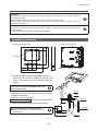
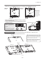
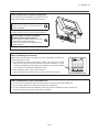
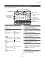
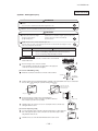
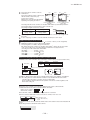
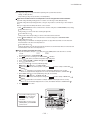
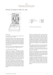
'12 • KX-DB-175
3.3 Instullation manual for wired remote controller
PJZ012D077 a
(a) Model : RC-EX1A(Option parts)
1 . Safety Precautions
This installation manual describes the installation methods and precautions related to the remote control. Use this
manual together with the user’s manuals for the indoor unit, outdoor unit and other optional equipment. Please read
this manual carefully before starting the installation work to install the unit properly.
Safety precautions
●Please read this manual carefully before starting installation work to install the unit properly.
Every one of the followings is important information to be observed strictly.
WARNING
Failure to follow these instructions properly may result in serious consequences such as
death, severe injury, etc..
CAUTION
Failure to follow these instructions properly may cause injury or property damage.
It could have serious consequences depending on the circumstances.
●The following pictograms are used in the text.
Never do.
Always follow the instructions given.
●Keep this manual at a safe place where you can consult with whenever necessary. Show this manual to installers
when moving or repairing the unit. When the ownership of the unit is transferred, the “Installation Manual”
should be given to a new owner.
WARNING
Ask a professional contractor to carry out installation work according to the installation manual.
Improper installation work may result in electric shocks, fire or break-down.
Shut OFF the main power supply before starting electrical work.
Otherwise, it could result in electric shocks, break-down or malfunction.
Do not install the unit in appropriate environment or where inflammable gas could generate, flow
in, accumulate or leak.
If the unit is used at places where air contains dense oil mist, steam, organic solvent vapor, corrosive
gas (ammonium, sulfuric compound, acid, etc) or where acidic or alkaline solution, special spray, etc.
are used, it could cause electric shocks, break-down, smoke or fire as a result of significant
deterioration of its performance or corrosion.
Do not install the unit where water vapor is generated excessively or condensation occurs.
It could cause electric shocks, fire or break-down.
Use the specified cables for wiring, and connect them securely with care to protect electronic
parts from external forces.
Improper connections or fixing could cause heat generation, fire, etc.
Seal the inlet hole for remote control cable with putty.
If dew, water, insect, etc. enters through the hole, it could cause electric shocks, fire or break-down.
-
280 -
—2—
'12 • KX-DB-175
When installing the unit at a hospital, telecommunication facility, etc., take measures to suppress
electric noises.
It could cause malfunction or break-down due to hazardous effects on the inverter, private power
generator, high frequency medical equipment, radio communication equipment, etc.
The influences transmitted from the remote control to medical or communication equipment could
disrupt medical activities, video broadcasting or cause noise interference.
CAUTION
Do not install the remote control at following places.
It could cause break-down or deformation of remote control.
(1) Where it is exposed to direct sunlight
(2) Near the equipment to generate heat
(3) Where the surface is not flat
Do not leave the remote control with its upper case removed.
When the upper case is removed, put it in a packing box or packing bag to protect internal PCBs or
other parts from dust, moisture, etc.
—3—
-
281 -
'12 • KX-DB-175
Request
Be sure not to install R/C at a place where temperatures around the installation surface of R/C may differ largely from
actual room temperature.
Difference between detected temperature and actual room temperature could cause troubles.
The correction for detected temperature by the R/C cannot offset such temperature difference because it corrects the
detected temperatures itself.
Request
Do not install the R/C at a place where it is exposed to direct sunlight or where surrounding air temperature exceeds 40°C
or drops below 0°C.
It could cause discoloration, deformation, malfunction or breakdown.
Installation procedure
PCB side (Viewed from rear)
83.5
120
18.3
Dimensions (Viewed from front)
Fixing holes
37
23
23
USB port Terminal Block
Sensor
19
120
① To remove the upper case from the bottom cases of R/C
· Insert the tip of flat head screwdriver or the like in the
recess at the lower part of R/C and twist it lightly to
remove.
Take care to protect the removed upper case
from moisture or dust.
② Connect wires from X and Y terminals of R/C to X and Y
Wall
Conduit
Locknut
terminals of indoor unit.
R/C wires (X, Y) have no polarity.
In case of embedding wiring (When the wiring is retrieved “Backward”)
Switch box
Bushing
③ Embed the switch box and the R/C wires beforehand.
50
8
Seal the inlet hole for the R/C wiring with putty.
Seal with putty
● If dust or insect enters, it could cause electric shocks,
fire or breakdown.
200
—5—
-
282 -
R/C cable
'12 • KX-DB-175
2 . Accessories & Prepare on site
R/C main unit, wood screw (ø3.5 x 16) 2 pcs
User’s Manual, Installation Manual
Accessories
Parts procured at site
Item name
Switch box
For 1 piece or 2 pieces (JIS C8340 or
equivalent)
Thin wall steel pipe for electric appliance
(JIS C8305 or equivalent)
Q’ty
Remark
1
As required
These are not required when installing
directly on a wall.
When the cable length is longer than
100 m, the max size for wires used
in the R/C case is 0.5 mm2 . Connect
them to wires of larger size near
the outside of R/C. When wires are
connected, take measures to prevent
water, etc. from entering inside.
Lock nut, bushing (JIS C8330 or equivalent) As required
< 200 m
0.5 mm2 x 2-core
Suitably For sealing gaps
< 300 m
0.75 mm2 x 2-core
Molly anchor
As required
< 400 m
1.25 mm2 x 2-core
R/C cable (0.3 mm2 x 2 pcs)
As required See right table when longer than 100 m
< 600 m
2.0 mm2 x 2-core
Lacing (JIS C8425 or equivalent)
As required Necessary to run R/C cable on the wall.
Putty
3. Remote control installation procedure
Determine where to install the remote control
Wiring direction
“Using a switch box”
“Installed directly on a wall”
“Backward”
“Upper center”, “Upper left”
Installation space
Wiring
Cautions for selecting installation place
(1) Installation surface must be flat and sufficiently strong.
R/C case must not be deformed.
(2) Where the R/C can detect room temperatures accurately.
This is a must when detecting room temperatures with
the temperature sensor of R/C.
· Install the R/C where it can detect the average temperature in the room.
· Install the R/C separated from a heat source sufficiently.
· Install the R/C where it will not be influenced by the
turbulence of air when the door is opened or closed.
Select a place where the R/C is not exposed to direct
sunlight or blown by winds from the air conditioner or
temperatures on the wall surface will not deviate largely
from actual room temperature.
—4—
-
283 -
30mm
30mm
30mm
R/C temperature sensor
120mm
Installation
Secure minimum spaces for
disassembling the case.
Upper left and Upper right sides
……30mm or more
Bottom side…120mm or more
If using L-shaped
screwdriver, 50mm or
more is available.
'12 • KX-DB-175
④ When wires are passed through the bottom case, fix the bottom case at 2 places on the switch box.
Upper side
Upper side
Switch box
for 1 pc
Switch box
for 2 pcs
Bottom case
Bottom case
Downside
Cut out the thin
wall part at the
screw mounting
section with a
knife or the like
before tightening
the screw.
Downside
Wire outlet
Wire outlet
⑤ When fixing the bottom case diagonally at 2 places, cut out the
thin wall section on the case.
⑥ Fix wires such that the wires will run around the terminal screws
on the top case of R/C.
Wiring hole on bottom case
Cautions for wire connection
Use wires of no larger than 0.5 mm2 for
wiring running through the remote
control case, Take care not to pinch
the sheath.
Tighten by hand (0.7 N·m or less)
the wire connection. If the wire is
connected using an electric driver, it
may cause failure or deformation.
⑦ Install the upper case with care not to pinch wires of R/C.
In case of exposing wiring
(When the wiring is taken out from the “upper center” or “upper left” of R/C)
③ Cut out the thin wall sections on the cases for the size of wire.
Upper center
When taking the wiring out from the upper center,
open a hole before separating the upper and
bottom cases. This will reduce risk of damaging
the PCB and facilitate subsequent work.
When taking the wiring out from the upper left,
take care not to damage the PCB and not to
leave any chips of cut thin wall inside.
Upper left
Bottom case
Upper case
—6—
-
284 -
'12 • KX-DB-175
If the hole is cut too large, moisture, dust or insects may enter.
Seal gaps with putty or the like.
④ Fix the bottom R/C case on a
120mm
(for retrieving
wire from
upper left)
190mm
(for retrieving wire
from upper center)
8
flat surface with wood screws.
⑤ In case of the upper center,
pass the wiring behind
the bottom case. (Hatched
section)
⑥ Fix wires such that the wires
will run around the terminal
screw of the top case of R/C.
⑦ Install the top case with care
not to pinch wires of R/C.
Main/Sub setting when more than one remote control are used
Main-Sub setting for use of two or more R/Cs
Up to two units of R/C can be used at the maximum for 1 indoor unit or 1 group.
One is main R/C and the other is sub R/C.
Operating range is different depending on the main or sub R/C.
R/C function
Main
Run/Stop, setting temperature, fan speed and flap
○
direction operations
High power and energy-saving operations
○
Energy-saving setting
○
R/C sensor
○
Test run menu operation
○
Room temperature range setting
○
Indoor unit settings
○
Individual flap control
○
Operation data display
○
Error history display
○
Indoor unit
X Y
R/C cable (No polarity)
X Y
X Y
R/C
“Main”
R/C
“Sub”
Set the “Main” and “Sub” as described at Section 7.
—7—
-
285 -
Sub
○
○
-
-
-
-
-
-
-
○
'12 • KX-DB-175
Note: Connection to personal computer
It can be set from a personal computer via the USB port (mini-B).
Connect after removing the cover for USB port of upper case.
Replace the cover after use.
If dust, insect, etc. enters, it could cause electric
shocks or breakdown.
Special software is necessary for the connection.
For details, view the web site or refer to the engineering data.
Do not connect to a personal computer
without using the special software.
USB port
Do not connect the personal computer to the USB
simultaneously with other USB devices.
It could cause malfunction or breakdown of R/C or
personal computer.
Cover
Note: Initializing of password
Administrator password (for daily setting items) and service password (for installation, test
run and maintenance) are used.
○ The administrator password at factory default is “0000”. This setting can be changed
(Refer to User's Manual). When the administrator password is forgotten, it can be
initialized, if the [Highpower] and the [Energy-saving] buttons are pushed simultaneously
for 5 seconds on the administrator password input screen.
○ Service password is “9999”, which cannot be changed.
When the administrator password is input, the service password is also accepted.
Note: Combination of R/C and indoor unit
(1) It can be used as the combination of Main and Sub with RC-E3 to -E5 type of wireless R/C (optional part).
(2) It can be combined with FD-V or FD-KX E6 type and later types of indoor units
(3) In cases of combination with FD-V or FD-KX E6 type unit, there are some controlling items which cannot be used.
If operating such items, the message “Invalid request” is displayed.
—8—
-
286 -
'12 • KX-DB-175
4. Functions and menu items of Remote control
Names and functions of sections on R/C (Operating section)
⑤LCD display (With backlight)
③
switch
④Operation lamp
⑥USB port (mini-B)
①
②
switch
switch
Touch panel system, which is operated by tapping the LCD screen with a finger, is employed for any operations
other than the ① Run/Stop, ② High power and ③ Energy-saving switches.
①
switch
One push on the button starts operation and
another push stops operation. (★)
②
switch
Pushing this button starts the high-power operation.
(★)
switch
③
Pushing this button starts the energy-saving
operation. (★)
④ Operation lamp
This lamp lights in green (yellow-green) during
operation. It changes to red if any error occurs.
⑤ LCD (With backlight)
A touch on the LCD lights the backlight.
The backlight turns off automatically if there is no
operation for certain period of time.
Duration of the backlight lighting can be changed.
(★)
When the backlight is setting ON, if the screen is
tapped while the backlight is turned off, the
backlight only is turned on. (Operations of switches
①, ② and ③ are excluded.)
⑥ USB port
USB connector (mini-B) allows connecting to a
personal computer.
For operating methods, refer to the User's manual
attached to the software for personal computer
(Utility software of Eco-touch remote control RCEX1)
Request
· When connecting to a personal computer, do not connect
simultaneously with other USB devices.
Please be sure to connect to the computer directly, without
going through a hub, etc.
★ See User's manual for details.
—9—
-
287 -
'12 • KX-DB-175
Names and functions of sections on R/C (Display)
* All icons are shown for explanation.
TOP screen
①Clock, R/C name display
②Icon display
③Menu button
⑤Change set temp
button
④Change operation
mode button
⑥Change flap
direction button
⑧Timer button
⑦Change fan speed
button
⑨Message display
① Clock, R/C name display
Displays the current time (★) and the name of R/C
(★)
② Icon display
Each icon is displayed when one of following
settings is going on.
W h e n t h e p e a k - c u t When setting is made
from the sub R/C.
timer is set.
(★)
When the central control When the periodical
inspection is necessary.
(Optional) is running.
(★)
During the ventilation When ”filter sign” is up.
(★)
operation
(★)
When the Permission/ When the weekly timer
Prohibition setting is made. is set.
(★)
(★)
When the paek-cut timer is set.
(★)
③ Menu button
When setting or changing other than the following
④ – ⑧, touch the menu button. When menu items
are displayed, select one and set.
④ Change operation mode button (★)
Displays the operation mode which is selected
currently. Tap this button to change the operation
mode.
⑤ Change set temp button (★)
Displays the temperature which is set currently.
Tap this button to change the set temperature.
⑥ Flap direction button (★)
Displays the flap direction which is selected
currently. Tap this button to change the flap direction.
⑦ Fan speed change button (★)
Displays the fan speed which is selected currently.
Tap this button to change the fan speed.
⑧ Timer button (★)
Displays simplified contents of the timer which is
set currently.
(When two or more timers are set, a content of the
timer which will be operated immediately after is
displayed.)
Tap this button to set the timer.
⑨ Message display
Operation status of air conditioner and messages
related to R/C operations, etc, are displayed.
★ See User's manual for details.
— 10 —
-
288 -
'12 • KX-DB-175
PJA012D730A
Installation manual for wired remote controller
(b) Model : RC-E5(Option parts)
Read together with indoor unit's installation manual.
WARNING
Fasten the wiring to the terminal securely and hold the cable securely so as not to apply unexpected stress on the
terminal.
Loose connection or hold will cause abnormal heat generation or fire.
Make sure the power supply is turned off when electric wiring work.
Otherwise, electric shock, malfunction and improper running may occur.
The wiring inside the rem
The sheath should be pe
The peeling-off length of
CAUTION
DO NOT install the remote controller at the following places in order to avoid malfunction.
(1) Places exposed to direct sunlight
(2) Places near heat devices
(3) High humidity places
(4) Hot surface or cold surface enough to generate condensation
(5) Places exposed to oil mist or steam directly
(6) Uneven surface
DO NOT leave the remote controller without the upper case.
In case the upper cace needs to be detached, protect the remote controller with a packaging box or bag in
order to keep it away from water and dust.
Accessories
Prepare on site
Connect the remote cont
terminal block.
Connect the terminal of r
with the terminal of indoo
(X and Y are no polarity)
Wiring route is as shown
depending on the pulling
Install the upper case as
the screws.
In case of exposing cord
Installation and wiring of re
Wiring of remote controll
Maximum prolongation o
If the prolongation is ove
But, wiring in the remote
of the case according to
connecting section. Be c
100 - 200m.....................
Under 300m ...................
Under 400m ...................
Under 500m ...................
Remote controller, wood screw (ø3.5 16) 2 pieces
Remote controller cord (2 cores) the insulated thickness in 1mm or more.
[In case of embedding cord] Erectrical box, M4 screw (2 pieces)
[In case of exposing cord] Cord clamp (if needed)
Installation procedure
Open the cover of remote controller , and remove the screw under the
buttons without fail.
Remove the upper case of remote controller.
Insert a flat-blade screwdriver into the dented part of the upper part
of the remote controller, and wrench slightly.
Pulling out from upper
X wiring : 215mm
Y wiring : 195mm
Master/ slave setting when
Screw
A maximum of two remote co
Indoor units
[In case of embedding cord]
Embed the erectrical box and remote controller cord beforehand.
Rem
Controller cord
Erectrical box
(Prepare on site)
Remote controller
SW1 "Master"
Prepare two M4 screws (recommended length is 12-16mm) on site, and install the lower case to erectrical box.
Choose either of the following two positions in fixing it with screws.
Upper part
Upper part
Lower case
Wiring oulet
Lower case
Connect the remote controller cord to the terminal block.
Connect the terminal of remote controller (X,Y) with the terminal of
indoor unit (X,Y). (X and Y are no polarity)
Install the upper case as before so as not to catch up the remote controller cord,
and tighten with the screws.
[In case of exposing cord]
You can pull out the remote controller cord from left upper part or center upper part.
Cut off the upper thin part of remote controller lower case with a nipper or knife,
and grind burrs with a file etc.
M4 screw
2 (Prepare on site)
The thin part
Upper
At the same time, a mark or a
This is the software's adminis
Lower
Upper
Lower case
Lower
289 -
The indication when power
When power source is turned
communication between the r
Master remote controller :
Slave remote controller : "
Lower case
Install the lower case to the flat wall with attached two wooden screws.
-
Set SW1 to "Slave" for the
Note: The setting "Remote co
controller in the position
The air conditioner ope
master/ slave setting of
Tighten the screws after
cutting off the thin part of
screw mounting part.
Lower part
Wiring oulet
Lower part
Remote
SW1
When remote controller canno
appear.
Check wiring of the indoor un
'12 • KX-DB-175
ote controller
ply unexpected stress on the
Connect the remote controller cord to the
terminal block.
Connect the terminal of remote controller (X,Y)
with the terminal of indoor unit (X,Y).
(X and Y are no polarity)
Wiring route is as shown in the right diagram
depending on the pulling out direction.
Sheath
Upper
Upper case
Board
Lower
The wiring inside the remote controller case should be within
The sheath should be peeled off inside the remote controller case.
The peeling-off length of each wire is as below.
ion.
gh to generate condensation
am directly
kaging box or bag in
Board
Lower
Wiring
In case of pulling out from
upper left
0.3mm2
Sheath
Upper
The range of temperature setting
Upper case
Wiring
In case of pulling out from
upper center
(recommended) to 0.5mm2.
Pulling out from upper left Pulling out from upper center
X wiring : 215mm
X wiring : 170mm
Y wiring : 195mm
Y wiring : 190mm
The peeling-off length
of sheath
Install the upper case as before so as not to catch up the remote controller cord, and tighten with
the screws.
In case of exposing cord, fix the cord on the wall with cord clamp so as not to slack.
Installation and wiring of remote controller
Wiring of remote controller should use 0.3mm2 2 core wires or cables. (on-site configuration)
Maximum prolongation of remote controller wiring is 600 m.
If the prolongation is over 100m, change to the size below.
But, wiring in the remote controller case should be under 0.5mm2 . Change the wire size outside
of the case according to wire connecting. Waterproof treatment is necessary at the wire
connecting section. Be careful about contact failure.
100 - 200m.........................0.5mm2 2 cores
Under 300m .......................0.75mm2 2 cores
Under 400m .......................1.25mm2 2 cores
Under 600
500m .......................2.0mm2 2 cores
s in 1mm or more.
crew (2 pieces)
)
Master/ slave setting when more than one remote controllers are used
Screw
A maximum of two remote controllers can be connected to one indoor unit (or one group of indoor units.)
Switch
Indoor units
SW1
Setting
Contents
M
Master remote controller
S
Slave remote controller
Remote controller cord (no polarity)
roller cord
Upper
Erectrical box
(Prepare on site)
Master
Remote controller
SW1 "Master"
Remote controller
SW1 "Slave"
Slave
Board
ll the lower case to erectrical box.
Lower
Set SW1 to "Slave" for the slave remote controller. It was factory set to "Master" for shipment.
Note: The setting "Remote controller thermistor enabled" is only selectable with the master remote
controller in the position where you want to check room temperature.
The air conditioner operation follows the last operation of the remote controller regardless of the
master/ slave setting of it.
hten the screws after
ing off the thin part of
ew mounting part.
M4 screw
2 (Prepare on site)
The thin part
Upper
cord,
pper part.
nife,
The indication when power source is supplied
When power source is turned on, the following is displayed on the remote controller until the
communication between the remote controller and indoor unit settled.
Master remote controller : "
"
Slave remote controller : "
"
At the same time, a mark or a number will be displayed for two seconds first.
This is the software's administration number of the remote controller, not an error cord.
Lower case
Lower
Upper
Lower case
The left mark is only an
example. Other marks may
appear.
When remote controller cannot communicate with the indoor unit for half an hour, the below indication will
appear.
Check wiring of the indoor unit and the outdoor unit etc.
Lower
-
290 -
When shipped, the range of set tem
Heating : 16~30˚C (55~86˚F)
Except heating (cooling, fan,
Upper limit and lower lim
Upper limit setting: valid during h
Lower limit setting: valid except
79˚F).
When you set upper and lower l
1. When TEMP RANGE SET
If upper limit value is set
During heating, you cannot s
If lower limit value is set
During operation mode exce
2. When
TEMP RANGE SET
If upper limit value is set
During heating, even if the va
But, the indication is the sam
If lower limit value is set
During except heating, even i
But, the indication is the sam
How to set upper and low
1. Stop the air-conditioner, and
seconds .
The indication changes to "F
2. Press
button once, and
3. Press
(SET) button,
4. Select "UPPER LIMIT
"
5. Press
(SET) button t
6. When "UPPER LIMIT
"i
Indication: "
SET
Select the upper limit va
(blinking)
Press
(SET) butto
After the fixed upper lim
7. When "LOWER LIMIT
"
Indication: "
SET
Select the lower limit val
(blinking)
Press
(SET) butto
After the fixed lower limi
8. Press ON/OFF button to fi
It is possible to finish by pre
ON/OFF button on the wa
unfinished change of settin
unavailable.
During setting, if you press
(RESET) button, you return
previous screen.
'12 • KX-DB-175
PJA012D730
Sheath
Upper
Upper case
Board
Lower
The range of temperature setting
Wiring
In case of pulling out from
upper center
ommended) to 0.5mm2.
he peeling-off length
of sheath
r cord, and tighten with
t to slack.
on-site configuration)
e the wire size outside
ry at the wire
ne group of indoor units.)
s
ontroller
ntroller
Upper
Board
Lower
"Master" for shipment.
the master remote
roller regardless of the
When shipped, the range of set temperature differs depending on the operation mode as below.
Heating : 16~30˚C (55~86˚F)
Except heating (cooling, fan, dry, automatic) : 18~30˚C (62~86˚F)
Upper limit and lower limit of set temperature can be changed with remote controller.
Upper limit setting: valid during heating operation. Possible to set in the range of 20 to 30˚C (68 to 86˚F).
Lower limit setting: valid except heating (automatic, cooling, fan, dry) Possible to set in the range of 18 to 26˚C (62 to
79˚F).
When you set upper and lower limit by this function, control as below.
1. When TEMP RANGE SET, remote controller function of function setting mode is "INDN CHANGE" (factory setting),
If upper limit value is set
During heating, you cannot set the value exceeding the upper limit.
If lower limit value is set
During operation mode except heating, you cannot set the value below the lower limit.
2. When TEMP RANGE SET, remote controller function of function setting mode is "NO INDN CHANGE"
If upper limit value is set
During heating, even if the value exceeding the upper limit is set, upper limit value will be sent to the indoor unit.
But, the indication is the same as the temperature set.
If lower limit value is set
During except heating, even if the value lower than the lower limit is set, lower limit value will be sent to the indoor unit.
But, the indication is the same as the temperature set.
How to set upper and lower limit value
1. Stop the air-conditioner, and press
(SET) and
(MODE) button at the same time for over three
seconds .
The indication changes to "FUNCTION SET ".
2. Press
button once, and change to the "TEMP RANGE " indication.
3. Press
(SET) button, and enter the temperature range setting mode.
4. Select "UPPER LIMIT " or "LOWER LIMIT " by using
button.
5. Press
(SET) button to fix.
6. When "UPPER LIMIT " is selected (valid during heating)
Indication: "
SET UP"
"UPPER 30˚C "
Select the upper limit value with temperature setting button
. Indication example: "UPPER 26˚C
"
(blinking)
Press
(SET) button to fix. Indication example: "UPPER 26˚C" (Displayed for two seconds)
After the fixed upper limit value displayed for two seconds, the indication will return to "UPPER LIMIT ".
7. When "LOWER LIMIT " is selected (valid during cooling, dry, fan, automatic)
Indication: "
SET UP"
"LOWER 18˚C "
Select the lower limit value with temperature setting button
. Indication example: "LOWER 24˚C
"
(blinking)
Press
(SET) button to fix. Indication for example: "LOWER 24˚C" (Displayed for two seconds)
After the fixed lower limit value displayed for two seconds, the indication will return to "LOWER LIMIT
".
8. Press ON/OFF button to finish.
oller until the
or cord.
It is possible to finish by pressing
ON/OFF button on the way, but
unfinished change of setting is
unavailable.
During setting, if you press
(RESET) button, you return to the
previous screen.
ur, the below indication will
Previous button
-
291 -
PJA012D730_2.pdf
2012/02/21
15:13:17
'12 • KX-DB-175
The functional setting
Note 1: The initial setting marked “
Item
Function No.
Remote controller
function02
Remote controller
function06
Remote controller
function07
Remote controller
function13
The initial function setting for typical using is performed automatically by the indoor unit connected, when remote
controller and indoor unit are connected.
As long as they are used in a typical manner, there wiil be no need to change the initial settings.
If you would like to change the initial setting marked “ ”, set your desired setting as for the selected item.
The procedure of functional setting is shown as the following diagram.
[Flow of function setting]
: Stop air-conditioner and press “
” (SET) and
Record and keep the
“
” (MODE) buttons at the same time for over three seconds.
setting
Finalize : Press “
” (SET) button.
Reset : Press “
” (RESET) button.
Select : Press
button.
Consult the technical data etc. for each control details
End
: Press ON/OFF button.
It is possible to finish above setting on the way,
and unfinished change of setting is unavailable.
Stop air-conditioner and press
“ ” : Initial settings
(SET) +
(MODE) buttons
“ ” : Automatic criterion
at the same time for over three seconds.
Start
(Remote controller function)
Function
01
02
03
04
05
06
C
07
M
Y
CM
08
09
MY
CY
CMY
K
Remote controller
function15
setting
Validate setting of ESP:External Static Pressure
Invalidate setting of ESP
03
Automatical operation is impossible
Temperature setting button is not working
Mode button is not working
To set other indoor unit, press
AIRCON NO. button, which
allows you to go back to the indoor
04
unit selection screen
(for example: I/U 000 ).
On/Off button is not working
05
Fan speed button is not working
06
Louver button is not working
07
14
15
16
17
18
If you change the range of set temperature, the indication of set temperature
will vary following the control.
If you change the range of set temperature, the indication of set temperature
will not vary following the control, and keep the set temperature.
-
If you change the remote controller function "14
you must change the indoor function "04
You can select the louver stop position in the four.
The louver can stop at any position.
.
.
or
-
-
(SET) butto
4. Press
or
button
Selecct " FUNCTION
FUNCTION " (indoor uni
(SET) butto
-
UH - Hi - Me - Lo
Hi - Me - Lo
Hi - Lo
Hi - Me
UH - UH - Hi - Me
UH - Hi - Me
UH - Me
UH - Hi
Initial function setting of some indoor unit is "HIGH SPEED".
6.
On the occasion of rem
"DATA LOADING" (Ind
Display is changed to "
The filter sign is indicated after running for 180 hours.
The filter sign is indicated after running for 600 hours.
The filter sign is indicated after running for 1000 hours.
The filter sign is indicated after running for 1000 hours, then the indoor unit will be stopped by
compulsion after 24 hours.
If you change the indoor function "04
",
you must change the remote controller function "14
You can select the louver stop position in the four.
The louver can stop at any position.
2. Press
5. Press
Indoor unit air flow setting
-
Press
or
butt
"No. and function"are in
controller function table
(For example)
" accordingly.
Permission/prohibition control of operation will be valid.
09
To be reset producing +2.0˚C increase in return air temperature of indoor unit.
To be reset producing +1.5˚C increase in return air temperature of indoor unit.
To be reset producing +1.0˚C increase in return air temperature of indoor unit.
-
11
. 12
13
",
" accordingly.
14
If you input signal into CNT of the indoor printed circuit board from external, the 15
indoor unit will be operated independently according to the input from external.
If you input into CNT of the indoor printed circuit board from external, all units which
connect to the same remote controller are operated according to the input from external.
In normal working indication, indoor unit temperature is indicated instead of airflow.
(Only the master remote controller can be indicated.)
Heating preparation indication should not be indicated.
19
-
To be reset for producing +3.0˚C increase in temperature during heating.
To be reset for producing +2.0˚C increase in temperature during heating.
To be reset for producing +1.0˚C increase in temperature during heating.
In case of Single split series, by connecting ventilation device to CNT of the
10
indoor printed circuit board (in case of VRF series, by connecting it to CND of the
indoor printed circuit board), the operation of ventilation device is linked with the
operation of indoor unit.
In case of Single split series, by connecting ventilation device to CNT of the indoor printed
circuit board (in case of VRF series, by connecting it to CND of the indoor printed circuit
board), you can operate /stop the ventilation device independently by
(VENT) button.
Airflow of fan becomes the three speed of
Airflow of fan becomes the two speed of
Airflow of fan becomes the two speed of
Airflow of fan is fixed at one speed.
-
08
11
13
STANDARD
FAN
SPEED
HIGH
SET
SPEED1, 2
-
1. Stop air-conditioner and
buttons at the same time
"FUNCTION SET " wil
Press
(SET) bu
The current setting of s
(for example) "AUTO R
selected
With the VRF series, it is used to stop all indoor units connected with the same outdoor unit immediately.
When stop signal is inputed from remote on-off terminal "CNT-6", all indoor units are stopped immediately.
Timer button is not working
Remote thermistor is not working.
Remote thermistor is working.
Remote thermistor is working, and to be set for producing +3.0˚C increase in temperature.
Remote thermistor is working, and to be set for producing +2.0˚C increase in temperature.
Remote thermistor is working, and to be set for producing +1.0˚C increase in temperature.
Remote thermistor is working, and to be set for producing -1.0˚C increase in temperature.
Remote thermistor is working, and to be set for producing -2.0˚C increase in temperature.
Remote thermistor is working, and to be set for producing -3.0˚C increase in temperature.
10
12
Note2: Fan setting of "HIGH SPEED"
Fan tap
How to set function
3. Make sure which do you
(remote controller functio
unit function).
Indoor unit with only one of air flow setting
Heat pump unit
Exclusive cooling unit
Note 3: As for plural indoor unit, set indoor functions to each master and slave indoor unit.
But only master indoor unit is received the setting change of indoor unit function “05 EXTERNAL INPUT” and “06 PERMISSION /
PROHIBISHION”.
Indoor unit No. are indicated only when
plural indoor units are connected.
Function
setting
02
(Indoor unit function)
” is decided by connected indoor and outdoor unit, and is automatically defined as following table.
Default
Model
"Auto-RUN" mode selectable indoor unit.
Indoor unit without "Auto-RUN" mode
Indoor unit with two or three step of air flow setting
Indoor unit with only one of air flow setting
Indoor unit with automatically swing louver
Indoor unit without automatically swing louver
Indoor unit with three step of air flow setting
Indoor unit with two step of air flow setting
16
17
Temperature indication is by degree C
Temperature indication is by degree F
To be reset producing -1.0˚C increase in return air temperature of indoor unit.
To be reset producing -1.5˚C increase in return air temperature of indoor unit.
To be reset producing -2.0˚C increase in return air temperature of indoor unit.
When heating thermostat is OFF, fan speed is low speed.
When heating thermostat is OFF, fan speed is set speed.
When heating thermostat is OFF, fan speed is operated intermittently.
When heating thermostat is OFF, the fan is stopped.
When the remote thermistor is working, "FAN OFF" is set automatically.
Do not set "FAN OFF" when the indoor unit's thermistor is working.
-
292 -
Press
(SET)
"SET COMPLETE" will
completed.
Then after "No. and fun
same procedure if you
finish, go to 7.
Change of indoor heat exchanger temperature to start frost prevention control.
Working only with the Single split series.
To control frost prevention, the indoor fan tap is raised.
7. Press ON/OFF button.
Setting is finished.
Drain pump is run during cooling and dry.
Drain pump is run during cooling, dry and heating.
Drain pump is run during cooling, dry, heating and fan.
Drain pump is run during cooling, dry and fan.
After cooling is stopped is OFF, the fan does not perform extra operation.
After cooling is stopped is OFF, the fan perform extra operation for half an hour.
After cooling is stopped is OFF, the fan perform extra operation for an hour.
After cooling is stopped is OFF, the fan perform extra operation for six hours.
After heating is stopped or heating thermostat is OFF, the fan does not perform extra operation.
After heating is stopped or heating thermostat is OFF,the fan perform extra operation for half an hour.
After heating is stopped or heating thermostat is OFF,the fan perform extra operation for two hours.
After heating is stopped or heating thermostat is OFF, the fan perform extra operation for six hours.
During heating is stopped or heating thermostat is OFF, the fan perform intermittent operation for five minutes
with low fan speed after twenty minutes' OFF.
During heating is stopped or heating thermostat is OFF, the fan perform intermittent operation for five minutes
with low fan speed after five minutes' OFF.
Connected “OA Processing” type indoor unit, and is automatically defined.
ON/OFF button
(finished)
Press
or
butt
Select the setting.
It is possib
unavailable
During set
Setting is m
How to check the curr
When you select from "
setting.
(But, if you select "ALL U
'12 • KX-DB-175
PJA012D730
omatically defined as following table.
Operation message
Function description:
setting description:
How to set function
ndoor unit.
" mode
ep of air flow setting
flow setting
swing louver
lly swing louver
air flow setting
flow setting
(SET)
(MODE)
1. Stop air-conditioner and press
buttons at the same time for over three seconds, and the
"FUNCTION SET " will be displayed.
,
Function No.
Fixing button
2. Press
(SET) button.
3. Make sure which do you want to set, " FUNCTION "
(remote controller function) or "I/U FUNCTION " (indoor
unit function).
flow setting
ERNAL INPUT” and “06 PERMISSION /
4. Press
or
button.
Selecct " FUNCTION " (remote controller function) or "I/U
FUNCTION " (indoor unit function).
5. Press
Finishing button
2
Starting button
1
6
door unit air flow setting
-
7
Indoor unit selection button
Previous screen button
(SET) button.
-
Hi - Me - Lo
Hi - Lo
Hi - Me
UH - Hi - Me
UH - Me
UH - Hi
H SPEED".
.
.
s.
s, then the indoor unit will be stopped by
",
6.
On the occasion of remote controller function selection
"DATA LOADING" (Blinking for 2 to 23 seconds to read the data)
Display is changed to "01
Indication is changed to "02 FAN SPEED SET".
Go to .
[Note]
(1) If plural indoor units are connected to a remote controller,
the indication is "I/U 000" (blinking)
The lowest number of
the indoor unit connected is indicated.
Function No.
Function
Press
(SET) button.
The current setting of selected function is indicated.
(for example) "AUTO RUN ON"
If "02 AUTO RUN SET" is
selected
connected with the same outdoor unit immediately.
nal "CNT-6", all indoor units are stopped immediately.
ature during heating.
ature during heating.
ature during heating.
".
Press
or
button.
"No. and function"are indicated by turns on the remote
controller function table, then you can select from them.
(For example)
" accordingly.
id.
On the occasion of indoor unit function selection
"DATA LOADING" (Indication with blinking)
Setting
Press
or
button.
"No. and function" are indicated by turns on the indoor unit function
table, then you can select from them.
(For example)
Press
or
button.
Select the setting.
Function No.
emperature of indoor unit.
emperature of indoor unit.
emperature of indoor unit.
mperature of indoor unit.
mperature of indoor unit.
mperature of indoor unit.
peed.
eed.
ted intermittently.
s set automatically.
tor is working.
Function
Press
(SET)
"SET COMPLETE" will be indicated, and the setting will be
completed.
Then after "No. and function" indication returns, Set as the
same procedure if you want to set continuously ,and if to
finish, go to 7.
Press
(SET) button.
The current setting of selected function is indicated.
(For example) "STANDARD"
If "02 FAN SPEED SET" is
selected.
Setting
Press
or
button.
Select the setting.
Press
(SET) button.
"SET COMPLETE" will be indicated, and the setting will be
completed.
Then after "No. and function" indication returns, set as the same
procedure if you want to set continuously , and if to finish, go to 7.
rt frost prevention control.
d.
(2) Press
or
button.
Select the number of the indoor unit you are to set
If you select "ALL UNIT ", you can set the same setting with
all unites.
(3) Press
(SET) button.
7. Press ON/OFF button.
Setting is finished.
n.
orm extra operation.
a operation for half an hour.
a operation for an hour.
a operation for six hours.
F, the fan does not perform extra operation.
F,the fan perform extra operation for half an hour.
F,the fan perform extra operation for two hours.
F, the fan perform extra operation for six hours.
FF, the fan perform intermittent operation for five minutes
FF, the fan perform intermittent operation for five minutes
When plural indoor units are connected to a remote controller,
press the AIRCON NO. button, which allows you to go back to
the indoor unit selection screen. (example "I/U 000 ")
It is possible to finish by pressing ON/OFF button on the way, but unfinished change of setting is
unavailable.
During setting, if you press
(RESET) button, you return to the previous screen.
Setting is memorized in the controller and it is saved independently of power failure.
How to check the current setting
When you select from "No. and funcion" and press set button by the previous operation, the "Setting" displayed first is the current
setting.
(But, if you select "ALL UNIT ", the setting of the lowest number indoor unit is displayed.)
automatically defined.
-
293 -