1
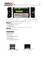
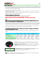
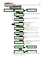
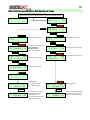
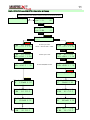
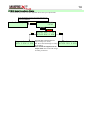
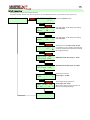
1
Intelligent Charger/Discharger
User's Manual
X6-Plus
INDEX
Specifications……………........................................................…......…..2
System Features……………………..............................................…....…2
Warnings……………………………......................................................……2
X6-Plus charger layout…………………….....................................…….3
General Setup & Notes………………................................…….....……4
Li-Po, Li-Ion, Li-Mn, LiFePO4 Operation & Display…….…..……5
A. Li-Po, Li-Ion, Li-Mn, LiFePO4 Balance Charge..................5
B. Li-Po, Li-Ion, Li-Mn, LiFePO4 Discharge.............................6
C. Li-Po, Li-Ion, Li-Mn Storage....................................................7
D. Li-Po, Li-Ion, Li-Mn, LiFePO4 Balance.................................8
E. Li-Po, Li-Ion, Li-Mn, LiFe Cycle...............................................9
NiMH, NiCD, Pb CHG or DHG Operation & Display............10
NiMH, NiCD, Pb CYCLE Operation & Display.........................11
ACT Mode for NiMH & NiCD Operation & Display..............12
Servo Test Mode Operation & Display.....................................13
POWER Mode Operation & Display..........................................14
SETUP menu Flow..........................................................................15
Error Messages................................................................................16
Warranty and Non-Warranty Service Conditions.................16
2
Thanks for purchasing Maxpro products. Pls read the User's Manual first to use your X6-Plus
Specifications
Input power:
Charge current:
Discharger current:
Max. charge power:
Max. discharge power:
Balance charge current:
Balance accuracy:
Voltage tolerance:
Capacity display:
Supported batteries:
Temperature control:
PC connection:
Additional functions:
Weight:
Size(LxWxD)
11~15V DC /15Amp (at maximum charge rate)
0.1~8.0A (0.1A/step)
0.1~3.0A (0.1A/step)
150Watt
15Watt
<400mA
<10mV
0.10%
0~9999mAH
1~6 cells Li-Po, Li-Ion, Li-Mn (2~6 cells in balance charge)
1~8 cells LiFePO4 (2~6 cells in balance charge)
1~18 cells NiMH, NiCd
1~12 cells(2~24V) Pb(SLA)
Automatically
USB port
Servo test (Linear, Speed, Deadband)
DC power supply (3.0~30V DC output)
450g
145x100x40mm (5.71"x3.94"x1.57")
System Features:
1. High power, high current, high-performance power conversion circuit. Maxpro X6-Plus uses advanced DC/DC
converter technology with high output conversion efficiency
2. The X6-Plus can be used with four types of Lithium batteries (Li-Po, Li-lon, Li-FePO4, Li-Mn) and has a build-in balancer.
3. Optimized the charging technique of NiMH/NiCd
4. Cooling FAN is controled automaticlly by internal temperature sensor and provides intelligent protection.
5. 16*2 backlit LCD that displays the active mode, battery voltage, charge current, pack temperature, capacity (mAH
added or removed) and charge/discharge times.
6. Programmable various charge settings.
Li** batteries: normal chargie, fast charge, balance, storage, discharge, charge/discharge cycle, and battery monitor.
NiMH/NiCd & Pb batteries: charge, discharge, charge/discharge cycle.
7. Perfect protection. The X6-Plus has protection for reversed polarity (input or output), low input voltage, battery
temperature, charging capacity and battery voltage overrun.
8. Battery interior resistance measurement with PC monitor software.
9. DC power supply mode can provide 3.0~30V adjustable DC to meet your requirement.
10. Build-in servo tester. Linear, Speed, Deadband of servos can be tested.
11. Firmware upgradable via USB port. The charge/discharge data can be recorded & analyzed by PC monitor software
& Battery analyzer software.
Warnings:
• Use a high quality power supply for input power source.
• Do not allow water, moisture, metal wires or other conductive material into the charger.
• Keep the charger away from children or pets at all times.
• Always be sure that the charger is properly configured for the correct battery type .
• Be sure that your lithium battery pack balance connector matches the multi-adapter type connected to the charger.
• Beware that the temperature of the charger shell & battery packs will increase during charge/discharge at high
power.
• Do not exceed the battery manufacturer's suggested maximum charge rates.
• Never charge batteries unattended.
• NEVER attempt to charge "non-rechargeable" cells.
• ACT charging mode should start with battery packs connected.
• Properly insulate and regularly inspect all connectors to eliminate the possibility of short circuit. Damage caused by
output short circuit is not covered by warranty.
• Do not open the case of the charger under any circumstances. Doing so will void the warranty.
3
X6-Plus charger layout
Check X6-Plus charger and the standard accessories you get. The following Standard items are included in the
package. Conntact your supplier if missing part or damage is found.
Standard items:
• Maxpro X6-Plus charger with input cables & clips
• One pair of output cables & alligator clips
• One temperature sensor
• One USB data cable
• One balance multi-adapter
• One CD (User's manual, PC monitor software, Battery Analyzer software inside)
Optional parts:
• Multi-connector output cable
• Multi-Battery Charging Adapter (2S/3S)
LCD display abbreviations:
•ACT:Activation mode
•CHG/CH: Charge mode
•DHG/DH: Discharge mode
•STO: Storage mode
•BAL: Balance mode
•CYCLE: Discharge/Charge cycle mode
•ST: Initial charging of Li-xx battery
•CC: Constant current
•CV: Constant voltage
•TR: Trickle charging of NiMH/NiCd Battery
•GV: Imbalance voltage between cells
The cell order of balance socket is
123456 from negative to positive.
Data port is used for temperature
sensor or servo connection.
4
General Setup & Notes
Before Charging/Discharging is started, Pls choose an appropriate AC/DC input power. When charging high voltage
batteries at high current (charger output 150W) the AC/DC Power Supply should be 12V minimum with rating of 160W
or more, to insure reliable performance. The X6-Plus allow you to use lower-rated power supplies reliably, but that total
charger output wattage will be limited accordingly.
1. Attach X6-Plus to an appropriate DC power supply.
2. Connect the Input Cables (Red+ & Black-) on left side of X6-Plus to the DC power supply. Then wait the initialization
finishing & "No Battery" display
3. Connect the output cables to the Output Port on the right side of X6-Plus first!! then connect the output cables to
your Battery Main wire Connector (in Series charging)
If in balance charging, pls do the following steps.
4. Connect the Balance Multi-Adapter to the balance socket on the right side of X6-Plus
5. Connect your Lithium battery Balance Connector to the Balance Multi-Adapter.
Suggestion: ALWAYS USE THE BALANCER(s) WHEN CHARGING LITHIUM BASED PACKS FOR SAFETY!!
NOTE:
•Please make absolutely sure that you properly identify the type of battery you are charging, the capacity in mAh,
and the number of cells wired in series and the pack voltage !!
•Please consult the documentation or labels provided with your battery to determine the correct capacity setting. It is
very important to get this right, as the charger uses the capacity setting to determine nominal charge rate (amperage),
capacity protection and safety termination. Incorrect settings could damage the battery, or result in hungry charge
•CAPACITY is selected in mAh. Selection is in increment/decrement of 100mAh. CURRENT is set in Ampere (divide
mAh by 1000 to get Amperage). For 2100mAh, 2.1A for 1C, and 4.2A for 2C and so on.
•After charging is finished, always disconnect the Battery main wire connectors from Output Cables set first, then
disconnect Output Cables set from charger.
•Be very careful to choose the correct voltage for the different types of battery. Following battery parameters for
reference.
DEC/INC, Scroll though the setting of parameter within Battery type, Cell numbers,
Battery capacity, Charge/Discharge current, Operation mode. And turn the LCD page
between Li** total voltage & cell voltage.
START/ENTER, Confirm the setting and skip to next parameter, Start Charge/Discharge
ESC/STOP, Cancel the setting and exit to last parameter, Stop Charge/Discharge
LiPo Normal CHG
6S 2200mAH 2.2A
Cursor indication: When the cursor flash, DEC/INC can be used to set the parameter.
e.g. "2200" flash, Use DEC/INC to scroll though the setting of capacity.
"Gray"means the cursor is flashing in this manual.
Timer: When you start Charging or Discharging in any mode, an internal timer starts counting at the beginning of
these cycles and is displayed on the charge and discharge screens.
5
Li-Po, Li-Ion, Li-Mn, LiFePO4 Operation & Display
A. Li-Po, Li-Ion, Li-Mn, LiFePO4 Balance Charge
Connect the Li** Battery Main wire Connector
& Balance Connector to X6-Plus
No Battery
22.72V GV: 16mV>
Type:LiPo
6S
INC
DEC
<3.78 3.79 3.78
3.80 3.78 3.79
ESC/STOP
START/ENTER
Press DEC & INC, Scroll through the setting within LiFe, LiPo, LiIon, LiMn.
22.72V GV: 16mV>
Type:LiPo
6S
Be Sure the charger is properly configured for the correct battery type.
ESC/STOP
START/ENTER
Press DEC & INC, Scroll through the setting of cell numbers.
22.72V GV: 16mV>
Type:LiPo
6S
X6-Plus will set the cell numbers automatically according to the Balance
Connector connected.
START/ENTER
ESC/STOP
Press DEC & INC, Scroll through the setting within
CHG DHG STO BAL
CYCLE
CHG, DHG, STO, BAL, CYCLE
•CHG: Charge mode
•DHG: Discharge mode
•STO: Storage mode
ESC/STOP
•BAL: Balance mode
•CYCLE: Discharge/Charge cycle mode
START/ENTER
LiPo Normal CHG
6S 2200mAH 2.2A
Press DEC & INC, Scroll through the setting of charging speed within
Slow, Normal, Fast.
Slow
ESC/STOP
Normal
Charge current during CC
0.5C
1C
Cut-off current during CV
1/20C
1/20C
Fast.
1C
1/20C
START/ENTER
LiPo Normal CHG
6S 2200mAH 2.2A
Press DEC & INC, Scroll through the setting of Battery Capacity.
100mAH/Step
Be Sure the battery capacity is configured correctly according to the
battery pack.
ESC/STOP
START/ENTER
Press DEC & INC, Scroll through the setting of Charging Current.
LiPo Normal CHG
6S 2200mAH 2.2A
0.1A/Step
X6-Plus will set the charging current=1C automatically according to the
battery pack capacity.
START/ENTER
“Charging Status”screen: the stage of the charge cycle (top left), the
pack voltage, the charging current, the pack temperature, the capacity
Starting charge
...............
charged and the time of charging.
•ST: Initial charging of Li-xx battery
•CC: Constant current
•CV: Constant voltage
CC>23.37V 2.20A>
20` 224mAH 0:05
INC
<3.90 3.89 3.90
3.90 3.89 3.89
INC
<4.20 4.20 4.20
4.20 4.20 4.20
DEC
Be. Be. Be
CHG END 25.20V >
20` 2198mAH 0:58
DEC
“Charging END”screen: the pack voltage, the pack temperature, the capacity charged and the time of charging.
The X6-Plus will stop charging when the cells voltage reach the cut-off voltage(4.20V for Lipo & LiMn, 4.10V for LiIon,
3.60V for LiFe) or reach the capacity protection(120% of battery capacity)
You can press “STOP” to stop charging anytime.
6
B. Li-Po, Li-Ion, Li-Mn, LiFePO4 Discharge
Connect the Li** Battery Main wire Connector
& Balance Connector to X6-Plus
No Battery
22.72V GV: 16mV>
Type:LiPo
6S
INC
DEC
<3.78 3.79 3.78
3.80 3.78 3.79
ESC/STOP
START/ENTER
Press DEC & INC, Scroll through the setting within LiFe, LiPo, LiIon,
22.72V GV: 16mV>
Type:LiPo
6S
LiMn. Be Sure the charger is properly configured for the correct battery
type.
ESC/STOP
START/ENTER
Press DEC & INC, Scroll through the setting of cell numbers.
22.72V GV: 16mV>
Type:LiPo
6S
X6-Plus will set the cell numbers automatically according to the Balance
Connector connected.
START/ENTER
ESC/STOP
Press DEC & INC, Scroll through the setting within
CHG DHG STO BAL
CYCLE
CHG, DHG, STO, BAL, CYCLE
ESC/STOP
Press DEC & INC, Scroll through the setting of Discharge Cut-off
START/ENTER
LiPo
6S
3.40V/CELL
Voltage.
0.05V/Step
DHG
0.7A
Be Sure the cut-off voltage is properly configured for the battery type.
Press DEC & INC, Scroll through the setting of Disharging Current.
ESC/STOP
0.1A/Step
START/ENTER
LiPo
6S
3.40V/CELL
X6-Plus will set the discharging current automatically according to the
battery pack's voltage & Max. discharge power
DHG
0.7A
e.g. 6S LiPo, the start voltage is 22.72V, X6-Plus Max. discharge power is
15W. So the Max. discharge current is 15/22.72=0.66A
“Discharging Status”screen: the pack voltage, the discharging
current, the pack temperature, the capacity discharged and the time of
discharging.
START/ENTER
DH>22.50V 0.66A>
20`
36mAH 0:03
INC
<3.41 3.40 3.40
3.42 3.40 3.41
INC
<3.41 3.40 3.41
3.42 3.40 3.41
DEC
Be. Be. Be
DHG END 20.45V >
20` 482mAH 0:40
DEC
“Discharging END”screen: the pack voltage, the pack temperature,
the capacity discharged and the time of discharging.
The X6-Plus will stop discharging when one of the cells voltage reach the
cut-off voltage
You can press “STOP” to stop discharging anytime.
ESC/STOP
20.47V GV: 12mV>
Type:LiPo
6S
INC
DEC
<3.41 3.41 3.42
3.42 3.40 3.41
Because of the battery characteristic, after press“STOP", the voltage will
rise little.
7
C. Li-Po, Li-Ion, Li-Mn Storage
Connect the Li** Battery Main wire Connector
& Balance Connector to X6-Plus
No Battery
22.72V GV: 16mV>
Type:LiPo
6S
INC
DEC
<3.78 3.79 3.78
3.80 3.78 3.79
ESC/STOP
START/ENTER
Press DEC & INC, Scroll through the setting within LiFe, LiPo, LiIon,
22.72V GV: 16mV>
Type:LiPo
6S
LiMn. Be Sure the charger is properly configured for the correct battery
type.
NO STOREGE MODE for LiFe battery
ESC/STOP
If you choose LiFe for STO mode, "Bat Type Err" will display
START/ENTER
Press DEC & INC, Scroll through the setting of cell numbers.
22.72V GV: 16mV>
Type:LiPo
6S
X6-Plus will set the cell numbers automatically according to the Balance
Connector connected.
START/ENTER
ESC/STOP
Press DEC & INC, Scroll through the setting within
CHG, DHG, STO, BAL, CYCLE
CHG DHG STO BAL
CYCLE
Press DEC & INC, Scroll through the setting of CHG/DHG Current.
ESC/STOP
0.1A/Step
START/ENTER
X6-Plus will set the discharging current automatically according to the
battery pack's voltage & Max. discharge power.
Storage Chg
LiPo
3S 0.7A
If the battery cell voltage is lover than 3.85V, X6-Plus will charge it to
3.85V. Following FLOW is the same as CHG display
If the battery cell voltage is higher than 3.85V, X6-Plus will discharge it to
START/ENTER
CC>22.79V 0.70A>
20`
36mAH 0:03
3.85V. Following FLOW is the same as DCH display
INC
<3.79 3.80 3.80
3.81 3.79 3.80
INC
<3.85 3.85 3.85
3.85 3.85 3.85
DEC
Be. Be. Be
CHG END 23.10V >
20` 180mAH 0:15
DEC
“Charging/Discharging END”screen: the pack voltage, the pack
temperature, the capacity discharged and the time of
charging/discharging.
X6-Plus will stop charging/discharging when the cells voltage reach
3.85V
ESC/STOP
23.13V GV:
Type:LiPo
4mV>
6S
INC
DEC
<3.85 3.85 3.86
3.85 3.86 3.85
Because of the battery characteristic, after press“STOP", the voltage will
rise or drop little according to the discharge or charge.
8
D. Li-Po, Li-Ion, Li-Mn, LiFePO4 Balance
Connect the Li** Battery Main wire Connector
& Balance Connector to X6-Plus
No Battery
22.72V GV: 16mV>
Type:LiPo
6S
INC
DEC
<3.78 3.79 3.78
3.80 3.78 3.79
ESC/STOP
START/ENTER
Press DEC & INC, Scroll through the setting within LiFe, LiPo, LiIon,
22.72V GV: 16mV>
Type:LiPo
6S
LiMn. Be Sure the charger is properly configured for the correct battery
type.
ESC/STOP
START/ENTER
Press DEC & INC, Scroll through the setting of cell numbers.
22.72V GV: 16mV>
Type:LiPo
6S
X6-Plus will set the cell numbers automatically according to the Balance
Connector connected.
START/ENTER
ESC/STOP
Press DEC & INC, Scroll through the setting within
CHG, DHG, STO, BAL, CYCLE
CHG DHG STO BAL
CYCLE
"Balance status" Screen: Time of balance, Imbalance voltage between
cells
"B" means balancing now.
START/ENTER
LiPo
0:01
Balance
GV: 16mV:>
Balancing current <400mA
INC
<3.79 3.80 3.80
3.81B3.79 3.80
INC
<3.79 3.79 3.79
3.79 3.79 3.79
DEC
Be. Be. Be
Balance END
0:08 GV: 2mV:>
DEC
“Balance END”screen: Time of balance, Imbalance voltage between
cells
Note: If the imbalance voltage between cells is big. The balance program
will take long.
You can press “STOP” to stop balancing anytime.
ESC/STOP
22.74V GV:
Type:LiPo
2mV>
6S
INC
DEC
<3.79 3.79 3.79
3.79 3.79 3.79
9
E. Li-Po, Li-Ion, Li-Mn, LiFe Cycle
Connect the Li** Battery Main wire Connector
& Balance Connector to X6-Plus
No Battery
22.72V GV: 16mV>
Type:LiPo
6S
INC
DEC
<3.78 3.79 3.78
3.80 3.78 3.79
ESC/STOP
START/ENTER
Press DEC & INC, Scroll through the setting within LiFe, LiPo, LiIon,
22.72V GV: 16mV>
Type:LiPo
6S
LiMn. Be Sure the charger is properly configured for the correct battery
type.
ESC/STOP
START/ENTER
Press DEC & INC, Scroll through the setting of cell numbers.
22.72V GV: 16mV>
Type:LiPo
6S
X6-Plus will set the cell numbers automatically according to the Balance
Connector connected.
START/ENTER
ESC/STOP
Press DEC & INC, Scroll through the setting within
CHG DHG STO BAL
CYCLE
CHG, DHG, STO, BAL, CYCLE
ESC/STOP
START/ENTER
Press DEC & INC, Scroll through the setting of Cycle order.
LiPo
6S CYCLE
DHG<->CHG:1 1.5A
DHG<->CHG or CHG<->DHG
ESC/STOP
START/ENTER
Press DEC & INC, Scroll through the setting of Cycle count.
LiPo
6S CYCLE
DHG<->CHG:2 1.5A
Input number of cycles desired
ESC/STOP
START/ENTER
Press DEC & INC, Scroll through the setting of CHG/DHG Current.
X6-Plus will set the discharging current automatically according to the
LiPo
6S CYCLE
DHG<->CHG:2 1.5A
battery pack's voltage & Max. discharge power.
If the setting current is lower than the Max. discharging current, X6-Plus
will discharge the battery according to the setting current.
START/ENTER
DH>22.50V 0.66A>
20`
36mAH 0:03
INC
DEC
<3.41 3.40 3.40
3.42 3.40 3.41
"Wait CHG" Screen: Waiting time, Battery type, Battery cells, Cycle count
Wait CHG
300S
LiPo
6S CYC:2
The waiting time can be setted in SETUP menu.
X6-Plus will cycle DHG & CHG
automatically according to the
cycle count until the cycle is
finished. You can press“STOP”
to stop CYCLE anytime.
CC>22.79V 0.70A>
20`
36mAH 0:03
INC
DEC
<3.79 3.80 3.80
3.81 3.79 3.80
Cycle finished until cycle count=0
You can press “STOP” to stop Cycle anytime.
Wait DHG
300S
LiPo
6S CYC:1
CHG END 25.20V >
20` 2198mAH 0:58
10
NiMH, NiCD, Pb(Lead-Acid) CHG or DHG Operation & Display
Connect the Ni** or Pb Battery Main wire Connector to X6-Plus
Suggestion: Temperature sensor should be connected to X6-Plus and touched with the battery.
10.71V
Type:NiMH
No Battery
8S
ESC/STOP
START/ENTER
ESC/STOP
10.71V
Type:NiMH
8S
ESC/STOP
START/ENTER
START/ENTER
CHG DHG STO BAL
CYCLE
Choose the CHG mode
CHG DHG STO BAL
CYCLE
Choose the DHG mode
ESC/STOP
ESC/STOP
START/ENTER
NiMH Fast
CHG
8S 2500mAH 1.5A
Choose the Fast or Normal
Fast: without TR
Normal: with TR
TR: Trickle charging
ESC/STOP
NiMH
8S
1.00V/CELL
DHG
1.5A
Set the DHG cut-off voltage
ESC/STOP
START/ENTER
START/ENTER
NiMH Fast
CHG
8S 2500mAH 1.5A
START/ENTER
Set the Battery capacity
NiMH
8S
1.00V/CELL
DHG
1.5A
Set the discharging current
ESC/STOP
START/ENTER
NiMH Fast
CHG
8S 2500mAH 2.0A
Set the charing current
START/ENTER
Starting charge
...............
CC>10.90V 2.00A
20` 56mAH 0:02
Charging status
•CC: Constant current
•TR: Trickle charging
DH> 9.80V 1.48A
20` 128mAH 0:05
Discharging status
Be. Be. Be
Be. Be. Be
CHG END 11.62V
32` 1856mAH 0:56
START/ENTER
X6-Plus will stop charging
according to the Peak
sensitivity-Delta V.
The Peak sensitivity can be
setted in SETUP menu
DHG END 8.04V
20` 518mAH 0:21
X6-Plus will stop discharging
if the battery pack voltage
reach cut-off voltage X Cells
11
NiMH, NiCD, Pb(Lead-Acid) CYCLE Operation & Display
Connect the Ni** or Pb Battery Main wire Connector to X6-Plus
Suggestion: Temperature sensor should be connected to X6-Plus and touched with the battery.
No Battery
10.71V
Type:NiMH
8S
ESC/STOP
START/ENTER
10.71V
Type:NiMH
8S
ESC/STOP
START/ENTER
ESC/STOP
CHG DHG STO BAL
CYCLE
ESC/STOP
START/ENTER
START/ENTER
NiMH
8S CYCLE
DHG<->CHG:1 1.1A
Set the Cycle order.
DHG<->CHG or CHG<->DHG
ESC/STOP
NiMH
8S CYCLE
CHG<->DHG:1 1.1A
ESC/STOP
START/ENTER
NiMH
8S CYCLE
DHG<->CHG:2 1.5A
START/ENTER
Set the Cycle count
ESC/STOP
NiMH
8S CYCLE
CHG<->DHG:3 1.5A
ESC/STOP
START/ENTER
NiMH
8S CYCLE
DHG<->CHG:2 1.5A
START/ENTER
Set the CHG/DHG Current.
NiMH
8S CYCLE
CHG<->DHG:3 1.5A
START/ENTER
Starting charge
...............
START/ENTER
DH> 9.80V 1.48A
20` 128mAH 0:05
CC>10.90V 2.00A
20` 56mAH 0:02
Wait CHG
300S
NiMH
8S CYC:2
Wait DHG
300S
NiMH
8S CYC:3
CC>11.10V 1.50A
20` 456mAH 0:32
DH>11.00V 1.50A
20` 880mAH 0:36
Wait DHG
300S
NiMH
8S CYC:1
Wait CHG
300S
NiMH
8S CYC:2
12
ACT Mode for NiMH & NiCD Operation & Display
ACT Mode can charge the NiMH or NiCD battery which voltage can't be detected by X6-Plus, It allows the user to
override the voltage sensing and force the charge cycle to run.
Be sure you know the battery specification & characteristic very well before you use ACT Mode.
Connect the NiMH/NiCD Main wire Connector to X6-Plus.
Bu sure the connection is right. If X6-Plus can't detect the voltage.
Pls press "ENTER" to get the ACT Mode
No Battery
ACT SERVO POWER
SETUP
Press DEC & INC, Scroll through the setting within ACT, SERVO,
POWER, SETUP
ESC/STOP
START/ENTER
NiMH
Activate
8S 2000mAH 1.0A
Press DEC & INC, Scroll through the setting within NiMH, NiCD
ESC/STOP
START/ENTER
NiMH
Activate
8S 2000mAH 1.0A
Press DEC & INC, Scroll through the setting of cell numbers.
Be Sure the cell numbers are configured correctly according to the
battery pack.
ESC/STOP
START/ENTER
NiMH
Activate
8S 2000mAH 1.0A
Press DEC & INC, Scroll through the setting of battery capacity.
100mAH/Step
Be Sure the battery capacity is configured correctly according to the
battery pack.
ESC/STOP
START/ENTER
NiMH
Activate
8S 2000mAH 1.0A
Press DEC & INC, Scroll through the setting of charging current.
0.1A/Step
Be Sure the charging current is proper for battery pack.
START/ENTER
Starting charge
...............
CC>10.90V 0.98A
20`
41mAH 0:02
“Charging Status”screen: the stage of the charge cycle (top left),
CHG END 11.68V
20` 1988mAH 1:50
“Charging END”screen: the pack voltage, the pack temperature,
the pack voltage, the charging current, the pack temperature, the
capacity replaced and the time of charging.
the capacity replaced and the time of charging.
You can press “STOP” to stop charging anytime.
13
Servo Test Mode Operation & Display
Servo Mode can provide the Linear, Speed and the Deadband test.
The servo load current should be lower than 500mA
Connect the Servo to the Data port on the right side of X6-Plus.
Then press "ENTER" to get the SERVO Mode
No Battery
START/ENTER
ACT SERVO POWER
SETUP
ESC/STOP
ESC/STOP
START/ENTER
START/ENTER
LINEAR
DEADBAND
SPEED
START/ENTER
Analog
Pulse:
Servo
uS
START/ENTER
Analog Servo
Pulse:1499uS
ESC/STOP
LINEAR
DEADBAND
SPEED
START/ENTER
Digital Servo
Speed:
S/60°
START/ENTER
Digital Servo
Speed:0.12S/60°
START/ENTER
ESC/STOP
LINEAR
DEADBAND
SPEED
START/ENTER
Analog Servo
Deadband: uS
START/ENTER
Analog Servo
Deadband: 2uS
Linearity Test
1. Choose servo property(Anolog or Digital)
2. Hold the DEC to scroll through the pulse width to low point. Hold the INC to scroll through the pulse width to high
point. 3. Check the servo running smooth or not to get the information of linearity, and search the shake point of
damaged servo.
Speed Test
Every servos have their own responding speed. and after a period of using, the speed will change also. By testing the
speed, we can get information of actual speed and select the servos with similar speed (e.g. CCPM helicopter)
1. Choose servo property(Anolog or Digital)
2. Press "ENTER" to run the speed test program. X6-Plus will output 5V DC to turn the servo left and right automaticlly.
Servo speed is displayed on the LCD (Base on 5V DC & 60° turn )
3. Press "STOP" to exit the function.
Dead band Test
Dead band Test can give the feedback of servo sensitivity. Generally, the dead band of normal servos shall be 1uS.
However, because of the precision of servo and assembly, the actual dead band will be different. By testing the dead
band, the actual size of dead band can be defined, which can help you select servos with the same sized dead band.
1. Choose servo property(Anolog or Digital)
2. The begining dead band is 0uS. the servo is at the middle position. Press DEC or INC to set the value(1uS/Step), until
the servo move slightly & regularly itself. The value is the dead band.
NOTE: The servo is at the middle position when the dead band value 0uS is setted.
14
POWER Mode Operation & Display
Power Mode can provide 3.0~30V adjustable DC to meet your requirement.
Be sure NO equipment connect to the output socket before you
choose the POWER Mode
No Battery
START/ENTER
ACT SERVO POWER
SETUP
ESC/STOP
START/ENTER
DEC
Output Set: 3.0V
OUT> 3.00V 0.01A
Output Set:12.8V
OUT>12.80V 0.01A
Press DEC/INC to Reduce/Add the
output voltage (3.0~30.0V).
The "OUT" value will change according
to the setting.
Then connect the equipment to the
output socket. The Current will change
according to the load.
INC
Output Set:30.0V
OUT>30.00V 0.01A
15
SETUP menu Flow
Following items can be setted in SETUP menu.
Key Beep ON/OFF, Buzzer ON/OFF, Temperature Cut-off, NiMH/NiCD Peak, Cycle wait time, Input power low.
No Battery
START/ENTER
ACT SERVO POWER
SETUP
Choose the SETUP function
ESC/STOP
START/ENTER
Key Beep ON
Buzzer
ON
>
Press DEC & INC, Scroll through the setting
within ON, OFF
ESC/STOP
START/ENTER
Key Beep ON
Buzzer
ON
>
Press DEC & INC, Scroll through the setting
within ON, OFF
ESC/STOP
START/ENTER
Temp Cut Off
50°
>
ESC/STOP
Temperature Cut-Off value range: 30~60°
if any battery you are charging or discharging
reaches this temperature the X6-Plus will stop
the charge/discharge.
START/ENTER
NiMH Peak 8mV
NiCD Peak 13mV
NiMH Delta Peak value range: 3~20mV
ESC/STOP
START/ENTER
NiMH Peak 8mV
NiCD Peak 13mV
NiCD Delta Peak value range: 10~20mV
ESC/STOP
START/ENTER
Cycle Wait Time
5min
>
Set the Cycle wait time
value range: 1~30 Min
ESC/STOP
START/ENTER
Input Power Low
Cut Off:11.0V >
START/ENTER
Setup Data Save
...............
Set the Input voltage protection.
value range: 10.8~16.0V
When input voltage is below the value, X6Plus will stop charge/discharge.
16
Error Messages
Connection Break
If the battery becomes disconnected during an operation.
Battery
Temperature Over
Battery temperature is too high to be charged.
Charge
Capacity
Over
BAT INCORRECT
POLARITY
Bat Type Err
The charged capacity reach 120% of setting capacity.
Output battery is connected to the output in reverse polarity(switch +/-).
Mistake the battey type for the function.
Warranty and Non-Warranty Service Conditions
Thanks for purchasing the products made by MAXPRO. We are pleased to provide the best after-sales services for our customers.
1. Our after-sales service for our charger includes:
a) Each charger is free from defects in materials and workmanship for a period of 1 year from the customer's original date of purchase.
b) Lifetime repair and maintenance service (It will be charged, we call it non-warranty service);
c) Free software upgrade service.
2. The product is covered under warranty service if it is coincident with both of the following conditions:
a) The product was originally purchased within the past one year. The original date is determined by the date written on the valid
receipt or invoice.
b) The problem is caused by the quality defects in materials or workmanship.
3. Nonresponsibility:
If there is any situation as below, then the product is not covered under warranty, then it will get non-warranty service.
a) A valid sales receipt or invoice within one year warranty period is not provided.
b) Product was damaged due to the changing / decomposing taken by the customer himself.
c) Product was damaged due to incorrect use or application, exposure to water or any other liquid, bang, knock and etc.
4. Software upgrade is always free on our website. Pls download it yourself.
5. Shipping cost
a) If the product is covered under warranty, Please contact the Maxpro's Distributor in / near your loaction for the warranty service to
avoid expensive shipping and handling fees. If customer want to send the charger to MAXPRO for service, the shipping cost from
customer to Maxpro is paid by the customer, and Maxpro will pay for the shipping cost for returning the repaired product to the customer.
b) If the product is not covered under warranty, all the shipping cost is paid by customer.
6. After-sales service processing:
a) If the product is out of work, and the customer determines it is damaged after careful check and test. Please directly contact the
person in charge of after-sales service of your local dealer or Maxpro(Contact us through telephone,e-mail and etc), and describe
detailedly the charger's situation.
b) The after-sales service person will help the customer to confirm if the defected product actually needs to be repaired or the problem is
just caused by mistakenly use and / or the another problem exists in the system--such as a defect in the input power, battery,etc.
c) If the product is determined to be repaired, please ship the defect product & situation description to your local dealer or Maxpro.
d) Maxpro evaluates the damage level of the defected products. If it needs to be charged, Maxpro will contact the customer though
telephone or e-mail or some other methods, and begin to repair the product after the service fee is confirmed by the customer.
e) The service time for most defected products is within 5 working days from the date when the dealer or Maxpro receives the product.
And the repaired product will be returned to the customer in time.
7. The authority of interpretation of warranty service conditions belongs to Maxpro RC Technology Co., Ltd.