1
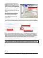
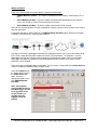
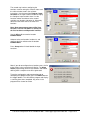
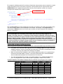
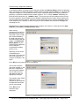
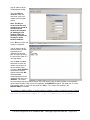
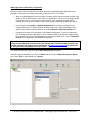
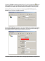
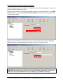
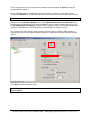
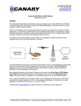
5 Gould Road, PO Box 2155
New London, NH 03257
Voice: (603) 526-9088
[email protected]
www.canarysystems.com
Call-Back Configuration for the CR800/CR1000
MultiLogger Application Note #19
Overview
Call-back is a process where a datalogger initiates communication back to a host PC based on alarm or
other conditions that are triggered on-site. It provides more responsive feedback to field measurements
especially when compared to traditional polling methods.
This application note will detail several common call-back scenarios and the required configuration of
MultiLogger software and communication devices.
RS-232 Direct Call-Back
The diagram illustrates a datalogger connection to a computer running MultiLogger to accept the callback events. The hardware may include a standard RS-232 connection, or a remote location using shorthaul or fiber-optic modems. Data are collected by MultiLogger and optionally imported into the
MultiLoggerDB database where alarm actions or other notification can be initiated.
There are 2 steps to the
MultiLogger configuration.
The first requires
configuration of the Alarm
Action to allow the CR800 or
CR1000 to initiate call-back
events.
Select the Program tab of the
Logger form to access the
Alarm Action drop-down.
Select RS-232 Direct CallBack.
Note: This option was
included beginning with
MultiLogger version 4.3.4.
Upgrades to the current
version are available from
the Support area of our
website.
Call-Back Configuration for the CR800/CR1000 – MultiLogger Application Note #19 – Page 1 of 12
The second step involves configuring the
location used for storing the call-back status
used in the call-back instructions. Use the
menu item Program | Input Locations or the
Input Locations button to display the Configure
Input Locations form. Use the Location
selector to advance to the second available
user location at location 32. Alternately
advance to the end of the list to create a new
location.
Note: Some measurement types utilize
User Location 1 so User Location 2 is
selected to avoid potential conflicts.
Use the Alias edit to name the location
CallBackStatus.
By default further call-back events WILL NOT be generated unless measurements return to non-alarm
values. This can be modified by editing the programming associated with the RS-232 Direct Call-Back
selection. Use the gear button located to the left of the drop-down to edit the programming, shown below.
'Note: Flag1 is used to disable repetitive alarms, it is reset if alarms go low
'Remove the mlFlag1 references to enable repetitive alarms
'Configure RS-232 port for call-back event
'Note this becomes the baud rate setting for MultiLogger
SetStatus("BaudrateRS232","-115200")
PakBus Neighbor Address
'Check our Alarm flag and alarm sent flag
if mlFlag8 then
if not mlFlag1 then
'Send Call-back variable
SendVariables(CallbackStatus,ComRS232,0,4094,0,0,"Public","CallBack",CallBackStatus,1)
'Set our alarm sent flag
mlFlag1 = -1
Endif
Else
PakBus Address
'Reset our alarm sent flag
mlFlag1 = 0
Endif
Lines in blue are the CRBasic programming lines. Flag 1 is set once an alarm is set, described by the
general alarm flag 8. Further call-backs won’t be activated until values return to normal. To disable this
feature and initiate call-back with every measurement interval remove the setting of the flag 1 location, as
highlighted. Additional logic could be incorporated to allow call-backs after a certain number of
measurement iterations or at a certain time of day. See the following section for an example of avoiding
additional call-backs until a specified number of measurement iterations are passed. Contact Canary
Systems for help with your specific application.
Note: When operating in more complex PakBus networking environments be sure to configure the
Pakbus Neighbor Address and PakBus Address settings in the SendVariables statement. In the
default configuration be sure the MultiLogger Gateway PakBus Address matches, default is 4094.
Call-Back Configuration for the CR800/CR1000 – MultiLogger Application Note #19 – Page 2 of 12
Modem Call-Back
There are 3 different Modem call-back options supported in MultiLogger:
•
COM220 Modem Call-Back – A Campbell COM220 with default settings, connected to CSI I/O
port.
•
CSI I/O Modem Call-Back – A generic modem connected (with appropriate RS-232 interface
such as the SC32B or SC932) connected to the CSI I/O port.
•
RS-232 Modem Call-Back – A generic modem connected to the RS-232 port.
Other devices and configurations may be supported for call-back, contact Canary Systems for assistance
with your application.
A schematic depiction is shown below for the COM220 Modem Call-Back option utilizing the Campbell
COM220. The architecture is similar for other modems.
The diagram illustrates a datalogger connected to a COM220 (using the CSI I/O port) connected to local
POTS, then a computer with phone modem and similar POTS connection. The computer is running
MultiLogger to accept the call-back events through the installed phone modem. Data are collected by
MultiLogger and optionally imported into the MultiLoggerDB database where alarm actions or other
notification can be initiated.
There are 3 steps to the MultiLogger configuration. The first requires configuration of the Alarm Action to
allow the CR800 or CR1000 to initiate call-back events.
Select the Program tab of
the Logger form to access
the Alarm Action dropdown. Select the
appropriate option, in this
case COM220 Modem
Call-Back.
Note: These options
were included beginning
with MultiLogger version
4.3.4. Upgrades to the
current version are
available from the
Support area of our
website.
Call-Back Configuration for the CR800/CR1000 – MultiLogger Application Note #19 – Page 3 of 12
The second step involves configuring the
locations used for storing the call-back status and
the call-back abort used in the call-back
instructions. Use the menu item Program | Input
Locations or the Input Locations button to display
the Configure Input Locations form. Use the
Location selector to advance to the second
available user location at location 32. Alternately
advance to the end of the list to create new
locations.
Note: Some measurement types utilize User
Location 1 so User Location 2 is selected as
the first location to avoid potential conflicts.
Use the Alias edit to name the location
CallBackStatus.
Advance to the next location, location 33, and
configure the Alias edit to name the location
CallBackAbort.
Press Accept when finished labeled the Input
Locations.
Note: If you do not configure these locations errors similar
to that shown in the screenshot will display. The Alarm
Action programming utilizes these locations and without
defining them a compiler error will be generated.
To test the configuration and programming prior to
attempting the Update function, press the INFO button on
the Logger toolbar. This will build the program and display
a summary form when completed. Any errors in the
program will be shown for review.
Call-Back Configuration for the CR800/CR1000 – MultiLogger Application Note #19 – Page 4 of 12
The last step involves configuring the phone number to be called in the case of a call-back event. Click on
the gear button located to the left of the Alarm Action. This loads the programming into an editor for
modification. Notice the Phone Number placeholders in the ModemCallBack instruction, as illustrated
below.
Enter the appropriate phone number to call for call-back in place of the nnnnnnnnnn values, keeping the
numbers enclosed in quotes.
Note: Do not enter any other commands, such as the ATDT command for dialing, or carriage
returns, these are supplied by the ModemCallBack instruction. Additional AT commands can be
entered by separating them with a semi-colon. Use two semi-colons in a row to insert a 1 second
delay. Use CHR(13) to send a carriage return.
'Initiate call-back from logger using COM220 connected to CSI I/O port
'Use COM220 defaults of SDC7 and 115200bps
'Receiving number must be enabled to accept call-back events
'Enter the phone number to call in place of "nnnnnnnnnn", use 2 semi-colons for 1 second delay
'Repetitive alarms are ignored, alarm status must go low to initiate following call-back
'Flag(1) is used to prevent repetitive call-back events
'Check for Alarm
if mlFlag8 then
Phone Number
Connect String
'Check if Call-back already sent
if not mlFlag1 then
'Make sure AbortExp is reset
CallBackAbort = 0
'Initiate call-back
ModemCallBack(CallBackStatus,ComSDC7,-115200,0,"nnnnnnnnnn","",60,120,CallBackAbort)
'Set our call-back sent flag
mlFlag1 = -1
endif
else
'Reset our Call-back sent flag
Baud Rate
mlFlag1 = 0
Interface Type
endif
Note: It is very important that the Interface Type and Baud Rate match the connected device. For
example, SDC7 and 115200 baud are the default settings for the COM220. There are configuration
DIP switches located inside the COM220 enclosure for selecting an alternate interface and baud
rate. The minus sign in front of the baud rate setting also configures auto-baud. Generally the
auto-baud setting should be used, otherwise the port becomes fixed at the selected baud rate,
regardless of what device is connected to the port.
Lines in blue are the CRBasic programming lines. Flag 1 is set once an alarm is set, described by the
general alarm flag 8. Further call-backs won’t be activated until values return to normal. To disable this
feature and initiate call-back with every measurement interval remove the setting of the flag 1 location, as
highlighted. Additional logic could be incorporated to allow call-backs after a certain number of
measurement iterations or at a certain time of day.
Call-Back Configuration for the CR800/CR1000 – MultiLogger Application Note #19 – Page 5 of 12
For example, the following code will re-activate call-back after measurements return to normal or a certain
number of iterations of the scan interval are passed. You will need to label an Input Location named
CallBackReset for this programming to function correctly. See the previous sections on using the
Configure Input Locations form to label a location.
Reset Count
'Check for Alarm
if mlFlag8 then
'Check if our Call-back resets should be reset
if CallBackReset >= 8 then CallBackReset = 0
'Check if first Call-back or we just reset it
if CallBackReset = 0 then
'Make sure AbortExp is reset
CallBackAbort = 0
'Initiate call-back
ModemCallBack(CallBackStatus,ComSDC7,-115200,0,"nnnnnnnnnn","",60,120,CallBackAbort)
'Increment our CallBackReset counter
CallBackReset = CallBackReset + 1
endif
else
'Reset our Call-back counter
CallBackReset = 0
endif
Note the Reset Count parameter highlighted in the code, this configures the number of repetitions of the
scan interval before another call-back attempt will be initiated. For example, if the Single Interval is
configured for 15 Minutes, then even if alarms persist another call-back attempt will not initiated for 2
hours (8 * 15 minutes).
Note: It is very important to optimize the call-back configuration with the number of systems and
other considerations for accessibility to the remote sites and/or originating computer. For
example, if the Single Interval is 1 minute then avoid configuring a potential call-back with every
scan interval, otherwise the system could become inaccessible with continued outgoing call-back
attempts. Another example - multiple systems configured for call-back with a short interval.
Consider a deployment with 15 systems all configured for continuous 15-minute call-backs. In this
case alarms generated on multiple systems could cause the originating computer and modem to
become unusable with negotiating multiple incoming calls.
Additional RS-232 Modem Call-Back Guidelines
When using the RS-232 port on the CR800/CR1000 with a connected modem keep the following in mind:
•
The modem must output the RING signal to turn on the CR800/CR1000 RS-232 port, alternately
additional characters can be sent out TXD to turn the port on. DTR will be asserted once the port
is turned on. You may also disable DTR handling in the modem.
•
Make sure the baud rate configured in the call-back programming matches the supported baud
rate for the connected modem. Usually it is best to fix the baud rate of the connected modem.
See the modem documentation for the command to fix the baud rate.
•
The cable (wiring below) must include a null-modem adaptor as the CR800/CR1000 RS-232
ports are configured DCE (Data Communications Equipment), modems are also DCE.
CR800/CR1000 DB-9F Null-Modem to Modem DB-9F and DB-25F wiring diagrams are as follows:
CR800/1000
DB-9F Pin
1
2
3
4
5
6
7
8
9
Description
DTR – Data Terminal Ready
TXD – Transmit Data
RXD – Receive Data
No Connection
GND – Ground
DTR – Data Terminal Ready
CTS – Clear to Send
RTS – Request to Send
RING – Ring signal
CR800/1000
I/O
O
O
I
O
I
O
I
Modem
DB-9F Pin
4
3
2
Jumper 1&6
5
Modem
DB-25F Pin
20
2
3
Jumper 6&8
7
8
7
9
5
4
22
Call-Back Configuration for the CR800/CR1000 – MultiLogger Application Note #19 – Page 6 of 12
Connect String Configuration Guidelines
In the ModemCallBack instruction used for dialing the modem the Connect String provides for identifying
when a connection is established between modems. When using the Campbell modems it is generally not
required to configure this string, however when using the ComRS232 option with third-party modems it
generally is required to include the actual modem response. This is usually “CONNECT” followed by the
baud rate of the connection, e.g. “CONNECT 9600”. The easiest way to test the modem connect string is
to use the computers internal modem and use Windows Hyperterminal to manually dial the modem and
view the modem connect response. Alternately connect the modem to be used at the datalogger directly
to the computer via a COM port. In either case you will need a modem connected to the datalogger for
answering the call.
Hyperterminal is a general purpose communications program, the shortcut is usually found in the Start |
Programs | Accessories | Communications group.
When starting
Hyperterminal you will first
be prompted to name the
connection. Use the COM
port number followed by
the baud rate to be used
for communicating with the
modem. Use Phone and
Modem Options in your
Control Panel to determine
which COM port is
assigned to the modem
you are using.
Optionally an icon can be
customized for the
connection. The name and
icon will be helpful for reusing the connection in the
future.
Press OK once the name and icon are configured.
You will now select the
connection method, i.e. the
port on the computer for
connecting to the modem.
Use the Connect using
drop-down to select the
appropriate COM port.
The example shows COM1
however the actual
selection on your computer
will depend on which port
you are connected to.
Press OK once the
Connect using is
configured.
Call-Back Configuration for the CR800/CR1000 – MultiLogger Application Note #19 – Page 7 of 12
You will advance to the
COM properties dialog.
Select the Bits per
second to match the
connection name and
modem communication
speed.
Note: The Bits per
second selection only
configures the speed of
communications
between the computer
(or datalogger) and
modem, it does not
generally configure the
connection speed
between modems!
Press OK once the Bits per
second is configured.
You will advance to the
communications window.
Hyperteminal will
automatically open the
port. Any errors opening
the port will be shown in a
message dialog.
Use the ATE1 and ATDT
commands to check the
modem connection and
dial the modem. After
issuing the ATE1<ENTER>
command the modem
should respond with OK.
Follow the ATDT
command with the phone
number to dial, then press
<ENTER>. You should
hear the modem dialing the phone number, the carrier detect of the answering modem, and negotiation
for the communications. After successful negotiation the CONNECT response, with baud rate, is issued.
The example shows a successful connection at 1200bps. This string is then entered in the
ModemCallBack instruction.
For example, the ModemCallBack instruction would be modified as follows to match the testing illustrated:
ModemCallBack(CallBackStatus,ComRS232,-2400,0,"5269004","CONNECT 1200",60,120,CallBackAbort)
Call-Back Configuration for the CR800/CR1000 – MultiLogger Application Note #19 – Page 8 of 12
MultiLogger After Call-back Do Configuration
Call-back initiates a data collection from the called computer running MultiLogger. Notification can be
provided in several ways to provide reporting of the call-back events. This includes:
•
When using MultiLoggerDB, email messages to include specific Output Parameters defined in the
database such as Quick Reports, Quick Charts or Spreadsheets can be sent. Also, paging, digital
I/O operations such as a activating an attached light or siren, or program execution can be
initiated. See the Insite Users Guide section 3.10 in regards configuring the Notification Events.
•
Use the Logger form Configure | Notification System form to configure emailing of arrays
including alarm arrays or specific elements from the alarm arrays. See the MultiLogger Users
Guide section 6.10 for more information on using the Configure | Notification System form.
•
Execution of call-back tasks configured in the Network Configuration. These can include batch
files for executing multiple applications or tasks, automated delivery of data files through email or
ftp, or execution of any user supplied program residing on the Gateway PC. These are After Callback Do Tasks configured in the Network Configuration.
Note: When using the Configure | Notification System options to generate emails as a result of
call-back events MsgServer must be running the gateway PC to facilitate sending the emails. See
FAQ #22 available in the Support area of our website at www.canarysystems.com for information
on using and configuring MsgServer to send emails.
This section will detail the setup for using the After Call-back Do functionality.
Select the Gateway to add the Task. Press the Add button to display the Add new Gateway or Device
form. Select Task as shown below. Press Accept.
Call-Back Configuration for the CR800/CR1000 – MultiLogger Application Note #19 – Page 9 of 12
Configure the Task Name as appropriate to help identify the Task. Use the file open button
to browse
to the executable to run, in this case Roobrik. Enclose the executable in quotes when using command
line parameters, the parameters direct Roobrik to load the mychart parameter file, then GO! and Quit.
See the Roobrik User’s Guide section 2.3 for more information on the Roobrik command line parameters.
Optionally additional tasks can be configured and selected using the After Task Do drop-down.
Configured tasks will display in the drop-down. Use the Run this task after collect data for this
gateway to run the Task after a scheduled data collection.
Next, configure the logger node to execute the Task. Select the logger node in the Network Configuration
and use the After Call-back Do drop-down to select the task. You may also select other logger nodes for
data collection to automate data collection from other loggers in the event of call-back from one logger.
See the following section on starting the Agent to handle the call-back events.
Call-Back Configuration for the CR800/CR1000 – MultiLogger Application Note #19 – Page 10 of 12
MultiLogger Enable Call-Back and Agent Configuration
Before activating the Agent be sure Call-Back is enabled for the ports that have dataloggers attached that
you wish to receive call-back events from.
For RS-232 Direct Call-Back select the COM port to be used to receive the call-back events. Check Allow
Call-back and then configure the Highest Call-back Baud Rate to match the setting in the programming
used for the Alarm Action.
When using any of the Modem Call-back Alarm Actions select the Modem node and check Allow Callback. The baud rate is negotiated between the modems so there is no baud rate setting.
Note: Only one device per Gateway can have call-back enabled. If the same computer must use
COM and Modem call-backs then configure a second local Gateway. Separate the 2 ports to each
Gateway, for example the COM device could be on Gateway1, the Modem on Gateway2.
Call-Back Configuration for the CR800/CR1000 – MultiLogger Application Note #19 – Page 11 of 12
The last step when using any of the call-back selections involves activating the Agent to accept the
incoming call-back requests.
Click on the Agent button on the Network Configuration toolbar to view the current Agent settings.
Configure the Schedule, or collection interval, to be used as the default if no call-back event is received.
Hint: You cannot use ASAP or Collect Once with call-back functionality.
Configure the Data Collection Method, when using the Data Recorded Since Last Collection a data
file named after the node name (in this case CR1000.DAT) will be used for recording data, when using
the Use Configuration File Settings the options in the Logger form will be used for collecting data and
naming the collected data file name. Generally Use Configuration File Settings is used.
Last configure the Failure Settings, make sure Stop Failure on Failure is UNCHECKED, otherwise a
communication failure on any node will stop the Agent, this includes the handling of incoming call-back
requests.
Press Start to start the Collection Agent.
Note: Call-back events will not be received and processed by the receiving computer unless the
Agent is started.
Call-Back Configuration for the CR800/CR1000 – MultiLogger Application Note #19 – Page 12 of 12