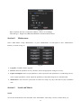
1
Stand alone Multi- channel
Digital Video Recorder
User Instruction Manual
VERSION 1.0
Before attempting to connect or operate this product, please read these instructions carefully and
save this manual for future use.
Warning
This apparatus must be earthed.
Apparatus shall be connected to a mains socket outlet with a protective earthing connection.
The mains plug or an appliance coupler shall remain readily operable.
To prevent fire or electric shock hazard, do not expose this apparatus to rain or moisture.
The apparatus should not be exposed to dripping or splashing and that no objects filled with liquids, such as
vases, should be placed on the apparatus.
All work related to the installation of this product should be made by qualified service personnel or system
installers.
The connections should comply with local electrical code.
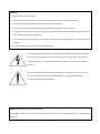
The lightning flash with arrowhead symbol, within an equilateral triangle, is intended to
alert the user to the presence of uninsulated ―dangerous voltage‖ within the product‘s
enclosure that may be of sufficient magnitude to constitute a risk of electric shock to
persons.
The exclamation point within an equilateral triangle is intended to alert the user to the
presence of important operating and maintenance (servicing) instructions in the
literature accompanying the appliance.
Important Notice: (for U.S. fileds only)
This product contains a CR Coin Cell Lithuim Battery which contains Perchlorate Material – special handling
may apply.
1
Limitation of liability
This publication is provided ―as is‖ without warranty of any kind, either express or implied, including but not
limited to, the implied warranties of merchantability, fitness for any particular purpose, or non-infringement of the
third party‘s right.
This publication could include technical inaccuracies or typographical errors. Changes are added to the
information herein, at any time, for the improvements of this publication and/or the corresponding product(s).
Disclaimer of warranty
In no event shall our company be liable to any party or any person, except for replacement or reasonable
maintenance of the product, for the cases, including but not limited to below:
(1) Any damage and loss, including without limitation, direct or indirect, special, consequential or exemplary,
arising out of or relating to the product;
(2) Personal injury or any damage caused by inappropriate use or negligent operation of the user;
(3) Unauthorized disassemble, repair or modification of the product by the user;
(4) Any problem, consequential inconvenience, or loss or damage, arising out of the system combined by the
devices of third party.
(5) Any claim or action for damages, brought by any person or organization begin a photogenic subject, due to
violation of privacy with the result of that surveillance-camera‘s picture, including saved data, for some reason,
becomes public or is used for the purpose other than surveillance.
2
INSTALLATION & SAFEGUARDS
Please read these instructions before operating the unit.
Installation.
Refer all work related to the installation of this product to qualified service personnel or system installers.
Avoid the following locations for installation.
* Places exposed to direct water, moisture, or sunlight directly
* Places subject to having strong vibration or impact
* Near magnetic field sources such as a television or speakers, magnet, etc.
* Steamy and oily places such as kitchens
* Places which are not level
* Place where condensation forms easily, where temperature changes greatly.
* Place the DVR in a well-ventilated place and do not place heat-generating objects on the unit.
Built-in hard disk drive
Hard disk drive is vulnerable to vibration. Handle it with care.
Performance and lifetime of hard disk drive is easily affected by heat (used at high temperature)
characteristically. It is recommended to use this unit at temperatures between 20℃-30℃{68℉-86℉}.
It is possible to damage it if it is moved while it motor is still running. Do not move it just after turning it
power on or off (for around 30 seconds).
A lifetime of hard disk drive is limited by use.
It is recommended to replace it after around 18000 hours of operation to prevent data loss from disk failures.
Write error may occur frequently after around 20000 hours of operation and the head and motor deterioration
may occur and will reach their lifetime after 30000 hours of operation when it has been used at the
recommended ambient temperature (approx. 25℃{77℉}).
When hard disk drive trouble occurs, replace it immediately. Consult your dealer for servicing.
When replacing the hard disk drives, take notice of the following.
Protect the hard disk drives from static electricity.
Do not keep them upright.
Do not use an electric screwdriver to fix them.
3
(Tightening torque: Approx. 0.49 N. m {5 Kgf.cm})
Avoid rapid changes of the temperature/humidity to prevent condensation.
(Acceptable change: within 15℃/h{59℉/h})
Before You Start.
1. Do not attempt to open or remove the covers. This may expose you to dangerous voltage or other hazards.
2. Installation should be performed by a qualified service person only.
3. This unit should be operated only from the type of power source indicated on the manufacturer‘s label.
Special Note.
If you need to change the TIME/DATE always clear the Hard Drive. If you don‘t follow this step first, it may
cause erratic behaviour of the DVR and possible loss of recordings.
1. It is recommended to use the same manufacturer when installing Hard Drives.
2. When backing up data, if there is any other data in USB disk, please save it, otherwise the original
documents will be deleted when video records backup.
4
Important safety instructions
Read and keep these instructions.
Heed all warning.
Do not connect this unit to an outlet to which appliances with high power consumption such as an air
conditioning or a copy machine is already being connected.
Do not use this apparatus near water.
To reduce the risk of electric shock, do not remove cover (or back).
Clean only with dry cloth.
Do not block any ventilation openings. Install in accordance with the manufacturer‘s instructions.
Do not install near any heat sources such as radiators, heat registers, stoves, or other apparatus (including
amplifiers) that produce heat.
Do not defeat the safety purpose of the polarized or grounding-type plug. A polarized plug has two blades
with one wider than the other. A grounding type plug has two blades and a third grounding prong. The wide
blade or the third prong are provided for your safety. If the provided plug does not fit into your outlet, consult
an electrician for replacement of the obsolete outlet.
Protect the power cord from being walked on or pinched particularly at plugs, convenience receptacles, and
the point where they exit from the apparatus.
Only use attachments/accessories specified by the manufacturer.
Use only with the cart, stand, tripod, bracket, or table specified by the manufacturer, or sold with the
apparatus. When a cart is used, use caution when moving the cart/apparatus combination to avoid injury from
tip-over.
Unplug this apparatus during lightning storms or when unused for long periods of time.
Refer all servicing to qualified service personnel. Servicing is required when the apparatus has been damaged in
any way, such as power-supply cord or plug is damaged, liquid has been spilled or objects have fallen into the
apparatus, the apparatus has been exposed to rain or moisture, does not operate normally, or has been dropped.
5
Content
Chapter I
Introduction......................................................................................................................................... 8
Chapter II System Installation ............................................................................................................................ 10
Section 1 Operating Environment............................................................................................................... 10
Section 2 HDD Installation ......................................................................................................................... 10
Section 3 Back panel ...................................................................................................................................11
2U case D1model and 2U case CIF model ...............................................................................................11
1.5U case model....................................................................................................................................... 12
Section 4 Audio Input ................................................................................................................................. 13
Section 5 External alarm in/out connection ................................................................................................ 13
Alarm in ................................................................................................................................................... 13
Alarm out ................................................................................................................................................. 14
Section 6 PTZ (pan, tilt and zoom) control connection .............................................................................. 14
ChapterⅢ DVR Operation ................................................................................................................................... 16
Section 1 DVR Front Panel ........................................................................................................................ 16
2UCase D1model and 2U Case CIF model ............................................................................................. 16
1.5Umodel ............................................................................................................................................... 17
Section 2 Mouse operation ......................................................................................................................... 19
Section 3 IR remote device ......................................................................................................................... 20
Section 4 Input mode introduction.............................................................................................................. 20
Chapter IV System operation .............................................................................................................................. 22
Section 1 Getting Started .............................................................................................................................. 22
Section 2 Login and Logout.......................................................................................................................... 22
System Login ........................................................................................................................................... 22
System Logout ......................................................................................................................................... 23
Section 3 Shortcut Menu .............................................................................................................................. 23
Section 4 Status Bar ...................................................................................................................................... 23
Section 5 PTZ Control .................................................................................................................................. 24
PTZ Setup ................................................................................................................................................ 24
PTZ Control ............................................................................................................................................. 25
Section 6 Manual Record.............................................................................................................................. 26
Section 7 Playback/Backup .......................................................................................................................... 26
Playback................................................................................................................................................... 26
Backup ..................................................................................................................................................... 28
Section 8 Main/Spot Video output ................................................................................................................ 29
Section 9 Matrix output ................................................................................................................................ 29
Section 10 Picture Adjustion ........................................................................................................................ 29
E-Zoom .................................................................................................................................................... 29
Picture Amplify........................................................................................................................................ 29
Section 11 E-Map ......................................................................................................................................... 29
Chapter V Parameters Setup Guide .................................................................................................................... 31
Section 1 Basic Parameter Setup .................................................................................................................. 31
General Setup........................................................................................................................................... 31
Time Display............................................................................................................................................ 32
6
Channel Name Setup and Display ........................................................................................................... 32
Section 2 HDD Management ........................................................................................................................ 32
Section 3 Record ........................................................................................................................................... 33
Record Parameter Setup........................................................................................................................... 33
Schedule Recording ................................................................................................................................. 34
Motion ..................................................................................................................................................... 35
External Alarm ......................................................................................................................................... 36
Video Sheltered........................................................................................................................................ 37
Video Lost................................................................................................................................................ 38
Alarm Elimination ................................................................................................................................... 38
Section 4 Communication........................................................................................................................... 38
Network ................................................................................................................................................... 38
PPPoE ...................................................................................................................................................... 39
DDNS ...................................................................................................................................................... 39
Email Setup.............................................................................................................................................. 39
Net Transfer Setup ................................................................................................................................... 40
Section 5 User ............................................................................................................................................. 41
Add User .................................................................................................................................................. 42
Rights Setup ............................................................................................................................................. 42
Section 6 Display ........................................................................................................................................ 44
Section 7 Abnormal .................................................................................................................................... 44
Section 8 Maintenance ................................................................................................................................ 45
Section 9 Serial and Matrix ........................................................................................................................ 45
Serial ........................................................................................................................................................ 45
Matrix ...................................................................................................................................................... 46
Section 10
Information ............................................................................................................................. 47
Log Information ....................................................................................................................................... 47
Version Information ................................................................................................................................. 47
User Information ...................................................................................................................................... 48
Chapter Ⅵ Frequency Asked Questions .............................................................................................................. 49
Appendix 1 HDD Capability Calculate .............................................................................................................. 50
7
Chapter I
Introduction
Thank you for choosing our stand alone Digital Video Recorder System.
Please pay attention to these instructions before using the DVR.
The manual explains the operation modes and performance criteria of our stand alone H264 DVR.
Please read the manual carefully before using the DVR, and install the system according to the instructions.
Mainframe software is subject to renewal without prior notice.
8
Product Introduction
1. Compress
Support PAL/NTSC video format, 25FPS (PAL), 30 FPS (NTSC), H.264; Support both variable bitrate
and variable frame rate.
Support dual stream, video config setting, Support channel masking function.
Support unlimited enlarge picture.
2. Record
2U case D1model support 16 CH realtime D1 record. 2U case CIF model max support 4D1+28CIF
realtime record. 1.5U case model max support 2D1+14CIF realtime record, or 16 CH non-realtime D1
mode.
Support record period, record quality setting; Support pre-record function.
Support SATA and eSATA port.
Support all channels playback and 4 channels playback
Support EXT3 files system. Support USB drives, USB hard disk backup. Backup creates a new folder.
Support cycle or none cycle record. Support redundant disk.
3. Control
Support exception alarm, motion detection alarm, external alarm, etc.
Support alarm email function.
Build-in E-map view.
Support main, spot, matrix video output independently. Support HDMI 1080P video output.
Support host-side import/export parameter.
Support user authority setting, the authority distribute to each channel respectively.
For 1.5U case model, support build-in SATA DVD writer.
Support customize human voice annotation. (This function is optional)
4. Network
Support TCP/IP protocol, DHCP, PPPoE, DDNS.
Support embedded WEB preview and IE browse.
Support remote parameters setup, Network control PTZ.
Support IPHONE, Symbian, Android and windows mobile cell phone for 3G live view.
9
Network download and playback the recorded files in DVR.
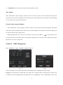
Chapter II
Section 1
System Installation
Operating Environment
The following operating environment for this DVR must be adhered to:
DVR Operating Environment
Items
Instructions
Electromagnetism
DVR‘ complies with National Electromagnetism
Radiation Standards.
Temperature
-10℃ to 55℃
Humidity
10 % to 95 %
Power Supply
AC220/230V 50/60HZ
Please pay particular attention to the following:
Keep away from heat sources and high temperatures and avoid direct sunlight.
Do not leave in humid places and never touch with wet hands.
Never spill liquids of any kind on the unit.
The unit is only to be opened by qualified persons.
Do not place other equipment on the DVR.
Section 2
HDD Installation
Equipment does not include the hard disk, configure the installation hard disk size needs to be calculated
according to the video programme, Specific calculation methods see Appendix 1. The chassis of the demolition
and hard drive installation, be sure to please professionals.
Users can also be accessed via the eSATA interface connected drive expansion box.
Installation of Hard Drive.
1. Remove DVR Lid.
2. Remove HDD mounting bracket, then fit HDD onto bracket using supplied mounting screws. Replace
HDD mounting bracket.
3. Connect the ATX power cable and HDD cable.
10
4. Replace the top of the DVR enclosure. Note: Please fix the screws at the back side of
DVR before the flank side while assembling the lid.
1.5U case model have different models of DVR: with 4HDD, with 2HDD and with 1HDD.
NOTE: Please format the hard disk before record.
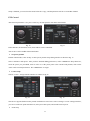
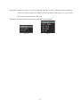
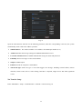
Section 3
Back panel
2U case D1model and 2U case CIF model
2U case CIF model
2U case D1 model
Fig. 1
Number
Function
Description
1
Power Supply Input(AC IN)
110/220V AC Voltage Input
2
Video Input(VIDEO IN)
Connect analog video input device, standard BNC port
3
Audio Input(AUDIO IN)
Connect analog audio input device
In 2U case CIF model, there is DB25 port, details refer to ―Section
4 Audio Input‖
4
Spot video output(SPOT VOUT) Spot video output support split screen, and playback control.
11
Matrix output(MATRIX VOUT)
5
Matrix output
Spot Audio output(SPOT AOUT) Auxiliary output playback of audio output, standard RCA
connector
Audio output (AOUT)
Audio of main output, standard RCA port
6
RS-232 port
System Debug port
7
VGA Port
The main video output, the output may carry out any operation
8
Network port(UTP)
Connect the network
9
USB Port
Connect USB mouse, data backup
10
HDMI Port
Connect HDMI displays
RS-485port
connect RS485 device, details refer to ―Section 6
and zoom) control connection‖
Alarm input(ALARM IN)
connect alarm input device(16CH, details refer to ―Section 5
External alarm in/out connection‖)
Alarm output(ALARM OUT)
connect alarm output device (4CH, details refer to ―Section 5
External alarm in/out connection‖)
eSATA Port
Connect the storage device with esata port, such as HDE
11
12
PTZ (pan, tilt
Note: Some port is optional, depend on detailed model.
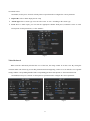
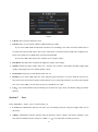
1.5U case model
Fig. 2 12V volts D.C. input model
Fig.3 110/220V AC voltage input model
Number
1
Function
Power Supply Input
Description
There are two types of DVR, one is 12V volts D.C. input, and other
12
is 110/220V AC voltage input
2
Video input (VIN)
Connect analog video input device, standard BNC port
3
Audio input (AIN)
connect simulate audio input device, standard BNC interface
VGA interface
Main video output, and can be whole controlled. VGA and HDMI
output are alternative; system will match the display device
automatically.
5
RS-232 port
System Debug port
6
eSATA port
Connect the storage device with eSATA port, such as HDE
7
Reserved
N/A
4
8
Spot video output(SPOT VOUT) Spot video output support split screen, and playback control.
Matrix output(MATRIX VOUT) Matrix output
Intercom input( )
Input port when intercom
Audio output (AOUT)
Audio of main output, output port for intercom, standard RCA port
10
USB Port
Connect USB mouse, data backup
11
Network port(UTP)
Connect the network
12
HDMI Port
Connect HDMI display device. VGA and HDMI output are
alternative; system will match the display device automatically.
+12V output(DC OUT)
12V DC output
RS-232 port
System Debug port
RS-485port
RS-485 port for connecting PTZ, keyboard and other equipment,
details refer to ―Section 6 PTZ (pan, tilt and zoom) control
connection‖
Alarm input(ALARM IN)
connect alarm input device(details refer to ―Section 5
alarm in/out connection‖)
External
Alarm output(ALARM OUT)
connect alarm output device (details refer to ―Section 5
alarm in/out connection‖)
External
9
13
Note: eSATA port, HDMI port and 12V DC output are optional, depend on detailed model.
Section 4
Audio Input
In 2U case D1 model, you can connect audio device directly by BNC port.
In 2Ucase CIF model, you can use DB25 converter in accessory to change DB25port to BNC port. The
number printed on BNC port is just the number of audio input channel.
1.5Ucase model, provide 4ch audio input and can connect audio device directly by BNC.
Section 5
External alarm in/out connection
Alarm in
The alarm input is NO/NC input. 4 CH series DVR has 4 ports for alarm input, 8 CH series DVR has 8 ports for
alarm input, 16 CH, 24CH and 32CH series DVR has 16 ports for alarm input.
13
Please connect signal port to ―ALARM IN‖ and GND port. Alarm type as NO in ―Main Menu—Rec—External
Alarm—Alarm Type‖ as NO. Alarm type as NC in ―Main Menu—Rec—External Alarm—Alarm Type‖ as NC.
Fig. 4
Note: external input voltage can not be higher than 5V.
Alarm out
Alarm output is NO/NC output.
If ―NO1‖ and ―COM1‖ was off, the alarm output disables, if ―NO1‖ and ―COM1‖ was connected, the alarm
output enable.
Fig. 5
Note: 24V DC (1A), 120V AC (1A) voltage and current are suggested.
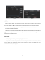
Section 6
PTZ (pan, tilt and zoom) control connection
T+ and T- ends of RS485 can be connected with the Rx+, Rx- on PTZ or High Speed Dome.
2U case D1 model and 2U case CIF model PTZ linkage should be as follows:
Fig. 6
1.5U model PTZ linkage should be as follows:
14
Fig. 7
Each camera press shown connection is completed, go to the Main Menu — PTZ Setup — PTZ menu, select
Connect head's port number, and you can set the camera's head address, baud rate and head a protocol parameters.
2UCaseD1model and 2UCaseCIFmodel need to choose the port number(RS485(1) or RS485(2))
。
WARNING: PLEASE SET ALL OF THE PTZ ADDRESSES DIFFERENTLY.
After the setup, click ―PTZ‖ on the shortcut menu to enter the PTZ control interface.
15
ChapterⅢ DVR Operation
Section 1
DVR Front Panel
2UCase D1model and 2U Case CIF model
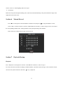
Fig. 8
No.
1
2
3
Name
specification
F1
Reserve
DISARM
Cancel alarm beep
LOCK
Logout
ESC
1.
SEARCH
Entry ―Search‖ interface
PTZ
Enter PTZ control mode
SPLIT
Split screen mode switch
MENU
Enter shortcut menu
ENTER
―OK‖ key
UP
1. ―UP‖ key
DOWN
―Cancel‖ key
2. Hide the status column in preview mode
2. Display the status column in preview mode
―Down‖ key
LEFT
1. ―Left‖ Key
2. Switch to last screen display in preview mode
RIGHT
1. ―Right‖ Key
2. Switch to next screen display in preview mode
0-9
1. Number key ―0-9‖ 2. Switch 1-9ch single screen display
3. In motion detect and shield alarm area setup interface, number key ―1‖ set area as
effective, number key ―2‖ set area as noneffective.
1-32
Corresponding channel record indicator (it lights when corresponding channel is
recording)
EDIT
Get into input method interface
-/--
Press this key under monitor mode, "--" will be marked in the top of screen, press the
number key will switch the right channel.(press 2 and 3, ch 23 will displayed)
16
4
5
Clockwise
in
shuttle circle
1. ―Right‖ Key
Anticlockwise
in shuttle circle
1. ―Left‖ Key
Clockwise out
shuttle circle
1. ―Down‖ key
2. Split screen mode switch in preview mode
Anticlockwise
out shuttle circle
1. ―UP‖ key
2. Split screen mode switch in preview mode
RUN
Working indicator, flashing after boot normally
SPOT
When current output is sport vout, lighting constantly
LINK
Network link indicator, lighting constantly when network is connected
ACTIVE
Network communication indicator, flashing when network is connected
PTZ
PTZ control indicator, lighting constantly when control PTZ
HDD
HDD indicator, flashing when access HDD date
ALARM
Alarm indicator, flashing when alarm is activated
RESERVE
Reserve
/PRESET
2. Switch to next screen display in preview mode
2. Switch to last screen display in preview mode
1. Start all channels‘ manual record
2. Fix the cursor or cancel the cursor fixed in mask area setup interface
3. Entry ―Preset‖ interface In PTZ mode.
/FOCUS+
/ZOOM+
1. Entry ―Search‖ interface
1. Fast forward
2. Zoom+ In PTZ mode
/IRIS+
1. Fast backward
2. Aperture+ In PTZ mode
/AUTO
1. Stop playback operation
mode
2. Stop all channels‘ manual record in monitor
3. Auto cruise in PTZ mode
/FOCUS-
1. Pause playback
2. Focus- In PTZ mode
/ZOOM-
1. Jump to next recorded file
2. Zoom- In PTZ mode
/IRISSPOT
1. Jump to previous recorded file
2. Aperture- In PTZ mode
MAINTAIN
Enter ―Maintenance‖ interface
6
2. Focus+ In PTZ mode
Switch between main vout and spot vout
Enter ―Shut Down‖ interface
1.5Umodel
Fig. 9
17
No.
1
Name
specification
DVD writer
slot
1.5U with dvd writer model can support DVD writer, and optional built-in DVD writer.
Open/close DVD writer
2
RUN
Working indicator, flashing after boot normally
HDD
HDD indicator, flashing when access HDD date
SPOT
When current output is sport vout, lighting constantly
NET
lighting constantly when network is connected, flashing when network is connected
SHIFT
Lighting constantly in SHIFT mode
ARMED
1.light after press "ARMED" to open alarm
2.close after press "ARMED" again to close alarm for external, motion and shelter
ALARM
Alarm indicator, flashing when alarm is activated
Shut down interface
3
(1)
(2)
1. Input number 1 or switch CH 1
2. Start all channels‘ manual record in SHIFT mode
3. in SHIFT mode, switch to the first shielding block in shield area interface
4. in SHIFT mode, set one block as effective area in motion and shelter area configure
interface
1. Input number 2 or switch CH 2
2. Pause playback in SHIFT mode
3. in SHIFT mode, switch to the second shielding block in shield area interface
4. in SHIFT mode, set one block as noneffective area in motion and shelter area
configure interface
(3)
1. Input number 3 or switch CH 3
2. Fast backward in SHIFT mode
3. in SHIFT mode, switch to the third shielding block in shield area interface
(4)
1. Input number 4 or switch CH 4
2. Fast forward in SHIFT mode
3. in SHIFT mode, switch to the fourth shielding block in shield area interface
4
ARMED
(5)
(6)
(7)
1. Input number 5 or switch CH 5
2. Open/Close alarm for external, motion and shelter in SHIFT mode
1. Input number 6 or switch CH 6
2. Entry ―Search‖ interface in SHIFT mode
1. Input number 7 or switch CH 7
2. Stop playback operation in SHIFT mode
3. Stop all channel manual record in SHIFT mode
(8)
1. Input number 8 or switch CH 8
2. Jump to previous recorded file in SHIFT mode
(9)
1. Input number 9 or switch CH 9
2. Jump to next recorded file in SHIFT mode
SPOT
(0/10+)
1. Input number 0 or switch 10+ channel
2. Switch between main vout and spot vout in SHIFT mode
PTZ
Enter PTZ control mode
18
MENU
Enter shortcut menu
SPLIT
Split screen mode switch
SHIFT
Get into "SHIFT" mode
up
1. ―UP‖ key
―Down‖ key
down
5
2. Display the status column in preview mode
left
1.―Left‖ Key
2. Switch to last screen display in preview mode
right
1.―Right‖ Key
2. Switch to next screen display in preview mode
1. ―OK‖ key
2. get into input interface
1. ―Cancel‖ key
ESC
Section 2
2. Hide the status column in preview mode
Mouse operation
This DVR supports USB mouse:
Plug the USB mouse into the USB port, and then the mouse cursor will appear on the screen.
User Login
Click the right mouse button on screen and a pop-up login box will appear; Move cursor to the
password input frame, double-click to enter the input box, click relevant character to input the password,
then click
to reserve and exit.
Entry Menu
Log into the system, click the right mouse button, a shortcut menu pops up, the user can select the
appropriate option to enter the menu.
Mouse Option
*Modify Number
Double-click to enter the input box, click relevant character to input number; Or
use trolley of mouse to modify number directly.
*Modify Character
Double-click to enter the input box, click relevant character to input character.
*Exit Menu
Click the right mouse button to exit menu step by step.
Adjusting the Monitor views
*Multiple-Screen Switch
On the monitor screen, click the right mouse button while you were out on the
shortcut menu, and then select the appropriate division to picture switch.
*Full Screen Image
when multi-screen display, move mouse cursor to a channel, double-click
mouse left key to view Full screen, double-click again will back full screen to
19
multi-screen.
*Picture Amplify
In a multiple screen appears, select a picture and press the left mouse button,
move the mouse to move the picture at this time. In a multiple-screen display,
move the mouse to the edge of the screen, when the mouse pointer changes to "
", a long press the left mouse button and move the mouse to resize the
screen size.
*E-Zoom
On the monitor screen, select a channel, and then click the right mouse button,
the shortcut menu, select "E-Zoom" into electronic mode, at this point with the
mouse in screen box out an area, the system will box out of the area to enlarge,
click the right mouse button to exit the zoom mode.
Section 3
IR remote device
Insert the battery, then aim the launch end at the receive end of DVR while using IR remote controller.
Remote control all key functionality specific see "DVR Front Panel". The following table for the remote
control-specific buttons:
Fig. 10
Buttons
Functions
MENU
Enter shortcut menu
ENTER
―OK‖ key
CANCEL
1. ―Cancel‖ key
column in preview mode
P/Z
Enter PTZ control mode
2. Hide the status
Split screen mode switch
F
Entry ―Search‖ interface
Cancel alarm beep
SELECT
N/A
N/A
N/A
SAVE
N/A
SETUP
N/A
RETURN
N/A
Section 4
Input mode introduction
DVR support many input modes: number, capital and lowercase letter input, character input and Chinese input.
20
Press ―EDIT‖ or ―
‖ on front panel or double-click to enter ―Input‖ interface, as shown in Fig. 11.
2U Case D1 model and 2U Case CIF model, press "Edit" to get into input interface.
1.5U model, press "Enter" to get into input interface.
Fig. 11
In the input interface, ―←‖ means ―delete‖, ― a A ‖ means uppercase or lowercase letter input switch, ―abc‖
means input mode switch. After finished, click
to reserve and exit.
21
Chapter IV
System operation
Section 1 Getting Started
Hint: make sure that the access of AC voltage and DVR's requirements, and ensure the DVR power outlet in the
middle of the Earth-side good grounding. Now make sure that you have a single HDMI or VGA display and hard
disk recorder.
Plug the mains lead into the DVR; Turn on the power switch on the back panel of DVR; The Power indication
light then comes on.
The device's power-on time may be long, please be patient.
Section 2 Login and Logout
System Login
Press any key of front panel, system will pop-up the login interface as shown in Fig. 12. Please select a user in
―User Login‖, then move cursor to password input box and press ―EDIT‖ or ―
‖ on front panel to get into input
interface in which to input the password. Language can also be selected in this dialogue box.
2U Case D1 model and 2U Case CIF model, press "Edit" to get into input interface.
1.5U model, press "
" to get into input interface.
Fig. 12
NOTE: 1. System default administrator ―admin‖, password ―123456‖, has the superlative level authority.
2. Assure system security, please enter ‗Main Menu-Setup-User‘ to modify original password of
Administrator in time.
22
System Logout
Method 1: 2U Case D1 model and 2U Case CIF model,press ―LOCK‖ on front panel to logout.
Method 2: Set ‗Auto Logout‘ as ON in ―Main Menu‖→ ―Setup‖→ ―General‖ and input idle time, then system will
auto-lock keyboard if no command input within the time set.
Method 3: Enter ―Main Menu-Setup—Maintenance‖ to enter ―Maintenance‖ interface, select ―LOGOUT‖ to
logout.
Section 3 Shortcut Menu
In monitor mode click the right mouse button, a shortcut menu pops up, as in
Figure 13.
Main Menu: You can do basic parameters, videos, hard drive
management, display settings, and so forth parameter settings.
Split: multiple-screen control。
REC: Enter manually video interface.
Playback: Enter the ―Search‖ interface, you can retrieve the video file
for playback or download.
PTZ: Enter the PTZ control interface.
Mute: Cancel Audio Output.
Switch to CVBS: Switch to the secondary output (SPOT VOUT) control.
E-ZOOM: Be a part of the screen displays the zoomed.
E-MAP: Enter the e-map mode.
Fig. 13
Section 4 Status Bar
In monitor mode, move the mouse to the picture below, the system automatically pop-up in the status bar, as
shown in Figure 14.
Figure 14
23
/
: Single-or multiple-screen, switch to the previous/next picture display.
: Switch the screen split screen mode.
: Alarms are triggered, cancel the warning.
Channel Status:The channel is a remote monitoring, shown in green; the corresponding channel video, shown in
red; the corresponding channel alarms triggered, displayed as yellow and the Flash.
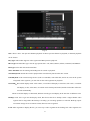
Section 5 PTZ Control
PTZ Setup
Enter ―Main Menu-PTZ Setup-PTZ ‖ as shown in Fig.15.
Fig. 15
PTZ Port: 2U Case D1 model and 2U Case CIF model, select a port for PTZ connection.
RS-485 parameters: Including baudrate, data bit, stop bit, parity bit, flow control, etc. These parameters
must be the same as those of PTZ Protocol.
PTZ Addr: Each PTZ has one different address.
Protocol: DVR had the following PTZ protocol: PELCO-D、PELCO-P2、PELCO-P1、W110、P3、PLD、
ENKEL、YAAN、SONY、JC4116、PD-NW、PD-CONST、PIH-1016、KRE301、PELCO9760、LILIN、
T3609HD、HD600、KTD、SAMSUNG、ELEC、PANASONIC、FASTRAX、DL-0001.
Speed: PTZ turning speed.
Rotate: When you set the PTZ is continuous send command.
Vertical: Reverse PTZ‘s vertical field.
Horization: Reverse PTZ‘s horizontal field.
24
Setup is finished, you can select the menu below the "copy", and the parameter will be set to another channel.
PTZ Control
After the PTZ parameter is set, press ―PTZ‖ key on front panel to enter PTZ control mode.
Fig. 16
Fig.17
In the interface, the direction, zoom, focus and Iris can be controlled.
Auto-cruise is in the middle of direction button.
Set preset position
In PTZ control mode, select ―Setup‖ to enter preset position setup dialog interface as shown in Fig. 17.
Select "Add New" Edit preset. After you have finished adding preferences, in the "ORIGINAL" drop-down box,
select the preset you just added, click on "Ok" to set the preset point is the current head position, click on the
"Call" can be invoked preferences. The "ORIGINAL" to origin.
Cruise Setup
Choose ―Cruise‖, and get into the interface as follows in fig.18.
Fig. 18
Fig. 19
This device supports different time periods run different cruise lines. Select "settings" to route settings interface,
you can set each route point-after-the-box, in the preset time spent, and switch between preset.
AUX setup
25
Choose ―AUX‖ to control lighting and screen wiper.
Scan Setup
Define the left point and right boundary point, click ON, head automatically at the point and the left edge of the
right point between the cruise.
Section 6 Manual Record
Press ―●‖ on front panel to start all channels‘ manual record, and press ― ‖ to stop all channels‘ record.
Select ―REC‖ in shortcut menu to enter the ―Manual Record‖ interface, as show in Fig.20. Users can control
the corresponding channel video. Analog channel via the port input analog video channel.
In the status bar, a channel in the video is shown in red.
Fig. 20
Section 7 Playback/Backup
Playback
Press ―Playback‖ on front panel to enter the ―Search Result‖ interface, as show in fig.21.
User can search the record file according to channel number, search time and record type; After search the record,
move the time point in time line, and click ―
‖ key to playback.
26
Fig. 21
CH: Choose "ALL" can open all channels playback. If choose specific channel to playback, 4 channels playback
can be chosen.
Play Type: This model supports video segment and JPEG pictures playback.
REC Type: Recorded files type. The file type options have ―All, Timer, Motion, Alarm, Command, and Manual‖.
File Type: Select lock files and normal files.
Start/ End Time: Set the starting and ending time for search or playback.
Search/Playback: Search the record or playback the record directly based on the time section.
USB Playback: If an external storage device (such as a USB disk, removable disk, and so on) exist on the system
recognized video segments, you can click on the video segments for playback.
Chart/File:Record file display mode. Click "chart", record file will display as time line; click "File", record file
will display as file, at this time, record file can be backup and locked, and the locked file will not be
covered automatically.
When record file display as chart mode, different record types will display in the time line as different color.
Backup: Click "file" to get into file display mode, then choose the file to backup. Select a single channel video
segment can be merged after the backup is a backup, you can merge produces a video file. Backup, require
an external storage device as FAT32 format, otherwise not recognized.
Lock: Video segments to display the file, you can set up a video segment for the locking, lock video segments in a
27
red font display. In the video and automatically overwritten, lock video segments are not overwritten.
: After search the record, move the time point in time line, and click ―
‖ key to playback.
: 1. Pause current video playback. 2. Continue playback from pause mode
: Stop current video playback.
: Skip to previous section and play automatically.
: Skip to next section and play automatically.
-: Play as 1/2, 1/4 of normal speed. At this point, click the "+" to return to normal playback status.
+ : Play as 2, 4, 8 times of normal speed. At this point, click the "-" to return to normal playback status.
: Playback in full screen mode.
Montage: Click "
" icon to montage in the playback interface. After finished, system will prompt user backup
the cut file to storage device.
Note: 1. If the matched files which you need can‘t be found, you can change start/end time and recorded files
type to get expected record files
2. If you need control playback by front panel, please make sure the ―SHIFT‖ LED is lighting.
Backup
Plug the USB storage device into the USB port. Press ―Playback‖ on the front panel to enter search interface.
In the ―Search‖ interface, click on the "files" will search for the videos section to display the file, select a video
segment, click on the "backup" for video backup.
When ―Merge‖ is selected, the searched record file should be single channel, and the whole size should be less than
2GB. If you select ―Merge‖, system will backup selected files to USB device as one file.
Backup device note:
1. Support Portable HDD storage and flash disk. Portable HDD storage or flash disk has to be formatted as FAT32
format before backup.
2. Backup user can create the folder, the data into the new folder.
Note: 1.USB device and DVR may be damaged if USB device falls off during backup.
2. 2U Case D1 model and 2U Case CIF model, do not connect more than 2 USB storage devices to one
DVR. 1.5U model, you can select USB device or DVD writer to backup.
28
Section 8 Main/Spot Video output
This model support main output and spot output, this two ports can be controlled and output independently.
User can switch the two controls by press "SPOT" in the front panel. Spot output controllable, on the front
panel of the ―SPOT‖ light is lit.
VGA and HDMI is main output, and can be whole controlled.
SPOT VOUT support split screen and playback control.
Section 9 Matrix output
The "MATRIX VOUT" in back panel is Matrix output. User can configure it as single channel or sequence in
"Main Menu—PTZ Setup--matrix".
Section 10 Picture Adjustion
This feature can be used only by a mouse operation.
E-Zoom
On the monitor screen, select a channel, and then click the right mouse button, the shortcut menu, select "EZoom" into electronic mode, at this point with the mouse in screen box out an area, the system will box out of the
area to enlarge, click the right mouse button to exit the E-Zoom mode.
Picture Amplify
In a multiple-screen display, move the mouse to the edge of the screen, when the mouse pointer changes to
"
", a long press the left mouse button and move the mouse to resize the screen size.
Section 11 E-Map
Choose "E-MAP" in shortcut menu to get into map interface. Right click to call the menu (as show in Fig.22),
user can lead in the map or add camera.
Lead in map: User can put the map into usb flash memory that need to lead in, choose "lead in map -usb" to
lead into the DVR(map must be JPG format,1280*1024, and the name is map).
29
Add Camera: Choose the camera you want to add, add completes, feel free to drag the camera position, in
camera area click the right mouse button to call out the camera menu (Figure 23), you can turn
on the video monitor, add alarm, and so on.
Add Alarm: After alarm added, map will have alarm hint when it's triggered.
Fig 22
Fig.23
30
Chapter V
Parameters Setup Guide
Section 1 Basic Parameter Setup
General Setup
Enter ―Main Menu-Setup-General‖ as shown in Fig. 24.
Move cursor with
and
on the front panel and select item with
and
.
DVR Name:Define DVR name. When you access DVR remotely, you can find all the DVR intuitively by
their names .If you want to modify the DVR name,
please move cursor to DVR name edit box and press
―EDIT‖ or ―
‖ key to enter into input mode.
System Time: Modify the system time.
NTP time: Select NTP time as ―On‖, you can entry
―NTP‖ interface to set service and interval of NTP.
Time Format:Setting the time format and DST.
Video Format:Auto adapt according to video input.
When video format is changed on operation, you need
to reboot the DVR to take effect. If there is no
connection video when powered on, the system defaults to PAL.
Fig. 24
Alpha: Adjust menu contrast. (Range from00 to 99. 99 stands for low contrast).
Auto logout: Host keyboard lock feature. Enable automatic log out function, you can set up automatic log
out of the wait time before, the default is 5 minutes without any operation, the system will automatically log
out. Do not turn on automatic log out function, the system does not automatically locks the keyboard, at this
point if the user wants to log out, you can press on the front panel of the "lock" key.
Output: Set video output for widescreen or normal mode, you can also set the resolution of the system's
output.
Mouse Sensitivity: Sets the mouse movement.
31
Sound Effect: You can turn on or turn off the front panel is pressed.
Time Display
Enter ―Main Menu-Setup-Display‖ interface. If the user want to preview the video and remote displays the
system time, please open the "Display Time" function; If you need to adjust the screen position of the time display,
you can enter the time location settings menu.
Channel Name Setup and Display
Enter ―Main Menu-Setup-Display‖ interface. If the user want to preview and remote displays the channel
name, please open the "Display Name" function; If you need to adjust the screen position of the name display, you
can enter the name location settings menu.
Modify channel name: move cursor to ―CH. Name‖ item box. Press ―EDIT‖ or ―
‖ on front panel to enter
text input interface, then channel name can be defined with uppercase or lowercase letter, number and symbol.
Details refer to section 4, chapter Ⅲ.
Section 2 HDD Management
Enter ―Main Menu-Setup—Harddisk‖ as shown in Fig. 25.
Fig. 25
Fig.26
Select a hard disk, you can format the hard disk, hard disk properties, redundant, and other settings.
Property: Set the properties of a hard disk. Set to "RW" disc, on the hard disk for read and write operations. Set
to "Read Only" disk, the hard disk for read operations. Set to "Redundance" disc, to "Redundance" menu, select
32
require redundant video channel.
Format: Select a hard disk, and click ―Format‖ to format the disk. 2U Case D1 model and 2U Case CIF
model, you can choose whether to separate space of the HDD to store the JPEG picture.
Redundance: A hard drive is set to redundant disk, and then the user can select a certain channel for
redundant video, the video will be the channel while recording on two hard drives, when a hard disk is
damaged, available on another hard disk-to-find data, implement double insurance.
Auto Overwrite: Select it, and it will overwrite the earliest recording when HDD is full.
HDD Alarm: HDD alarm will activate once the capacity of HDD is lower than a value set by user.
Note: 1. Do not format a disk while it is recording.
2. Format a HDD will delete all the data in it.
Section 3 Record
Record Parameter Setup
2U case D1 model support 16 CH realtime D1 record. 2U case CIF model max support 4D1+28CIF realtime
record (CH29-32 can be set as D1). 1.5U case model max support 2D1+14CIF realtime record (CH1 and CH9 can
be set as D1), or 16 CH non-realtime D1 mode.
Enter ―Main Menu-Rec—General‖ as shown in Fig. 27.
Fig. 27
In this interface, you can set the timing, alarm and motion detection, and other videos of basic parameters.
Priority: User can set different priorities for alarm recording, timing record, manual recording and motion
detection recording. Priority levels are highest, high, medium and low, when multiple recording modes
33
occurs, recording mode with the highest priority takes effect.
Pre-record Time: Activate pre-record function including ―OFF、5s、15s、25s、30s‖. Default pre-record time:
OFF.
MODE: In 1.5U case model, there are two options: 2D1/14CIF or 16D1. When select 2D1/14CIF, channel 1
and 9 can support D1 realtime recording and other channels can support CIF. When select 16D1, all channels
can support D1 with 8 frame rate recording.
Rec Type: Select a record type to set.
Channel Number: choose a channel to setup.
Resolution: The higher the resolution, the higher the quality of the images.
Quality: Define the image quality. There are 5 options: Low, Normal, Good, Better, and Best. High image
quality needs high bit rate size. Default quality: Good.
Encode: There are two options: CBR or VBR. Default coding type: VBR.
If you select VBR, DVR will adjust the actual bit rate according to the video movement. When there is
not much movement, DVR will use low bit rate, while there is much movement, DVR will use high bit rate.
In this case, DVR can save HDD usage and network bandwidth.
If you select CBR, DVR will use the fixed bit rate to compress image.
Frame Rate: Frame per second. Default frame rate: 25(PAL), 30(NTSC).
Bit Rate: If you select VBR, when the video input has great movement, we need to limit the max bit rate.
The bit rate selection has relations with resolution. If you select high resolution, you must select high bit rate.
If you select CBR, you can select bit rate size. Default bit rate: 512K
Copy:On a certain channel setup is finished, you can enter the "copy" menu, the channel settings to another
channel.
Schedule Recording
Enter ―Main Menu-Rec—Schedule‖ as shown in Fig. 28.
34
Fig. 28
Fig.29
Channel Number: Select a channel for setup.
Calendar: ―yy/mm/dd/‖ can be chose on the left of Calendar. For Example : choose 2008-10-20.
Time Period: Setup max two period for one day recording at most.
Today, Every day, Every week, Every Month: Take 2008-10-20( Monday) for example, select ―Today‖
means only recording during the set periods in 2008-10-20, select ―Every day‖ means recording during the
set periods everyday from 2008-10-20, select ―Every week‖ means recording during the set periods every
Monday from 2008-10-20 and select ―Every Month‖ means recording during the set periods at the 20th of
every month from 2008-10-20.
NOTE: Reset at the same day is available. The later mode will replace the former one. The function
can be applied to holiday setting.
Apply: Press ‗Apply‘ to save setting temporarily. For example: set recording periods in 2008-10-20 and press
‗Apply‘, then other recording period could be set in the same menu without exit. Press ‗OK‘ to save all
setting permanently.
NOTE: Only press ‘OK’ to save all setting permanently without lost when power is blackout. Press
‘Apply’ to save temporarily, all setting will lose when power is off.
Copy:On a certain channel setup is finished, you can enter the "copy" menu, the channel settings to another
channel.
List: Press ‗List‘ to list schedule recording time table (Max.120 records) of current channel. Records delete
operation is available in this menu.
Motion
1.5U model, need to press "Armed" in front panel to open alarm after configure the correct parameter.
35
Enter ―Main Menu-Rec—Motion‖ as shown in Fig. 30.
Fig. 30
Sensitivity:Select sensitivity of motion detection. Option including: High, Mid-high, Medium, Mid-low,
Low and Close. Select "off" when you close the motion detection feature.
Output CH: Select alarm output channel.
Full Screen: The channel, which selected, can be displayed as full screen.
Buzzer/Voice alarm: When motion alarm activated, select whether buzzer/voice alarm or not. voice alarm
function is optional.
Duration: Alarm triggered the alarm after the duration. The default is: 10 seconds.
Record Duration: Alarm triggered video time. The default is: 10 minutes.
Related Record: When motion alarm activated, relevant channel can be selected to record.
Shot: If the user needs to capture JPEG pictures, you can set each time an alert to catch the number and time
interval for the shoot.
Set Deffence: Enter "protection period settings" interface for alert window settings, in the set of valid time
period, the alarm is triggered, the system opens the appropriate treatments, including: buzzer alarm alert
channel, single-screen display, alarm output, the associated channel video, etc.
Area Setup: Set the alert that is triggered by active area, the default full-screen for the selected area.
Copy:On a certain channel setup is finished, you can enter the "copy" menu, the channel settings to another
channel.
External Alarm
When the add-ins have alarm input, the user can set the alarm output ports, buzzer alarm, single-screen display,
36
associated videos.
1.5Umodel, need to press "Armed" in front panel to open alarm after configure the correct parameter.
Input CH.: Select a alarm input port for setup
Alarm Type: This is sensor type. You can select ―NO‖ or ―NC‖ according to the sensor type.
PTZ: There is alarm input, you can start the appropriate channel head preset, automatic cruise or track.
Description of other parameters, see the "Motion".
Fig.31
Video Sheltered
When someone maliciously blocked the view of the lens, the image cannot be on the scene. By setting the
occlusion alarm can effectively prevent this phenomenon from happening. Video cover set includes cover regional
settings and the corresponding handled. The corresponding parameter description see the motion detection.
1.5Umodel,need to press "Armed" in front panel to open alarm after configure the correct parameter.
Fig.32
Fig.33
37
Video Lost
When the video signal for various reasons are lost, missing parameters by setting the video to discover this
phenomenon. The corresponding parameter description see the motion detection .
Alarm Elimination
Click ―DISARM‖ key on front panel to eliminate beep alarm if the alarm is activating.
Section 4
Communication
Network
Enter ―Main Menu-Setup—Communication-Network‖ as shown in Fig. 34.
Fig. 34
Mode: You can select model as Static, DHCP or PPPoE. On ―Static Address‖ status, IP Address, Net Mask,
Default Gateway and DNS should input by user self. On ―DHCP‖ status, IP Address and Net Mask will be
obtained by system automatically. PPPoE Configuration menu, enter the user name and password, and then
select the network mode to "PPPoE", the system automatically obtain an IP address, subnet mask, and
gateway, etc.
IP Address: Example 192.168.000.100. This IP address must not be conflicted with other IP.
Port: On PC client to access the hard disk recorder desired port number, Example 9998.
Subnet Mask: Example 255.255.255.000.
Gateway: Example 192.168.000.001 (Modem/Router local address).
38
DNS: Please set DNS as local network supplier's IP when DVR is accessed from WAN.
Center IP and Port: If you set this IP and port, when there is alarm and exception happened, DVR will send
information to that host IP.
Center: Setting IP address and port of DVR and connect it with internet. Enter 'Platform' to setup the IP address
of P2P service provider and enable this function. Access this server through IE and add the DVR which is going to
be operated. The others can be done in the same manner.
PPPoE
In the network settings menu, select network mode as PPPoE, then click "Set PPPoE", such as fig 35.
Please input the Username and Password provided by ISP. System will use PPPoE protocol to connect the net
with an auto-obtain dynamic IP address.
Fig. 35
Fig.36
DDNS
Set DNS as local network supplier's IP in ―Network‖ interface. Then select ―DDNS‖ as shown in Fig.36.
User can setup DDNS in this interface and access the DVR through the set domain name.
Provider: Could choose ―dyndns.org‖ and ―3322.org‖.
Host name: Domain name that user register. E.g. If the supplier is ―dyndns.org‖, and the registered domain
name is ―user.dyndns.org‖, you can input ―user‖ in ―Host name‖ option.
Username and Password: user name and password registered in supplier‘s website.
Email Setup
Enter ―Main Menu-Setup—Communication-Email Setup‖ as shown in Fig. 37.
39
Fig. 37
Open the mail function, and then set the following parameter, when the corresponding event fires, the system
automatically sends a mail to the address specified.
SMTP and Port:The sender's mailbox server address. The SMTP port number is 25;
Authent: Whether the message settings need SMTP authentication or not.
Username and Password: Use SMTP authentication using user name and password.
Email By: Receive messages see the sender address.
Subject: E-Mail subject
Email to: Fill in the recipient's e-mail address.
Touch Off Type: Select the type of event that triggers the message, including external alarms, motion
detection, alarm events such as video missing, hard drive exception, illegal access and other significant
events.
Net Transfer Setup
Enter ―Main Menu-Setup—Communication-Transfer‖ as shown in Fig. 38.
40
Fig.38
CH NO: Select relevant channel to setup.
Encode: There are two options: CBR or VBR. Default type: VBR.
If you select VBR, DVR will adjust the actual bit rate according to the video movement. When there is
not much movement, DVR will use low bit rate, while there is much movement, DVR will use high bit rate.
In this case, DVR can save HDD usage and network bandwidth.
If you select CBR, DVR will use the fixed bit rate to compress image.
Resolution: The higher the resolution, the higher the quality of the images.
Quality: Define the image quality. There are 5 options: Low, Normal, Good, Better and Best. High image
quality needs high bit rate size. Default quality: Good.
Frame Rate: Frame per second. Default frame rate: 25.
Bit Rate: If you select VBR, when the video input has great movement, we need to limit the max bit rate.
The max bit rate selection has relations with resolution. If you select high resolution, you must select high bit
rate. If you select CBR, you can select bit rate size. Default bit rate: 256k.
Copy:On a certain channel setup is finished, you can enter the "copy" menu, the channel settings to another
channel.
Section 5
User
Enter ―Main Menu-Setup—User‖ as shown in Fig. 39.
User list: list administrator and new user name. You can modify password, setup local rights, delete user in
this menu.
admin:Administrator who has supreme right on operation. Choose ―admin‖, and choose ―Modify‖ to get
into password modify interface, then press ―EDIT‖ or ―
41
‖ on front panel to modify password.
Fig. 39
Fig. 40
Add User
When you login as ―admin‖, you can add new user. Select ―Add‖ to enter into ―Add User‖ menu as shown in
Fig. 40. Press ―EDIT‖ or ―
‖ key on front panel to enter into input mode, then you can input the username.
The Viewer‘s default authority: information view, playback all channels and monitor all channels.
The operator can modify all parameters.
Add a user, you can set the password for that user. Move the cursor to the password box, press the "EDIT" or
―
‖ to enter the input method interface to enter a password. Password consists of numbers, uppercase and
lowercase letters, a maximum of 6 bits.
Rights Setup
When you login as ―admin‖, you can setup the rights for new users.
If you need to customize user permissions, in the user management interface to select the user, and then
select the "Modify" into "Authorisation" interface. In the permission set interface "Local Rights Setup", enter
"Authorisation" interface, such as Figure 41.
42
Fig. 41
Control PTZ: PTZ control.
Record: You can enter the ―main menu-Rec‖ interface, basic video recording, video recording,
alarm plan is set, you can also manually for hard disk management and control of the video.
Set Parameter: You can enter the ―main menu-settings‖ interface, basic settings, display settings,
communication settings, exceptions, and other parameters settings, or you can enter the ―main
menu-device‖ interface, to head its parameter, the settings for the serial port and matrix.
Search Information: You can enter the ―main menu-information" interface, review the log and
online user information.
Tool: Hard drive management, restart, shutdown, import/export parameter, a scheduled restart and
defense capabilities.
User manages explain:
Admin Logged on to the system, you can add a total of 29 new users, and modify the password for
all users. The average user login can only modify their own password. Login password 3 times to
enter the error will no longer be able to log in.
You cannot add the same user name.
Only Administrator can use the functions: USB upgrade, Restore parameter and format HDD.
43
Section 6
Display
Enter ―Main Menu-Setup—Display‖ as shown in Fig. 42.
Fig. 42
Monitor: Select the secondary output (SPOT VOUT) connection monitor type, Options are:Plane and
Sphere.
CH Map: Users can set the channel in 32 split screen is displayed.
CH. Shield: Select whether to display the selected channel in real time monitor screen.
Circle Monitoring: Set the split screen and Robin interval.
Mask: Provide you to mask the sensitive area. Shield area refers to the set portion of the image. Move cursor
to ―Mask Area Setup‖ and set the area. In the mask area setup interface, there are four small panes. You can
press ―1-4‖ keys to move the cursor. When you choose one pane, use direction keys to move the pane to your
hope position; And press ―●‖ key to fix the pane; Then use direction keys again to extend the pane.
Graphic: The system default 2 color mode, users can customize their 2 color patterns. Users can set a
different time period show the different color mode.
Section 7
Abnormal
Enter ―Main Menu-Setup—Abnormal‖ as shown in Fig. 43.
44
Fig. 43
When a machine has some exceptional condition, it can be set accordingly.
Abnormal type:Illegal Visit, HDD Full, HDD Error and Network Disconnect.
Section 8
Maintenance
Select ―Main Menu-Setup—Maintenance‖ or press ―MAINTAIN‖ on front panel to enter ―Maintenance‖
interface, as shown in Fig. 44.
Fig. 44
Upgrade: Via USB or FTP to upgrade.
Restore: Enter the parameter recovery interface, choose the appropriate setting for recovery.
Export and Import: Select "export parameter" will be export all of the parameters to a USB storage device.
Select "import parameters" will be import the parameters of the USB storage devices into this DVR.
Maintenance: You can set the system time to restart; also setup every day‘s start and every day‘s shutdown
time.
Section 9
Serial and Matrix
Serial
2U Case D1 model and 2U Case CIF model, enter ―Main Menu-PTZ Setup—Serial‖ as shown in Fig. 45.
45
Fig. 45
Usable Port: The system prompts the user to connect to port.
Setup parameters for 485(1)R+、R-: Including baud rate, data bit, stop bit, parity bit, flow control and so
on, they have to be consistent with parameters of connected series device(such as
keyboard).
Remark:Peripheral to the keyboard, you must add in the available ports, R- and R+, for keyboard to work
properly.
Matrix
Enter ―Main Menu-PTZ Setup—Matrix‖ as shown in Fig. 46.
Fig. 46
Monitor: Select the matrix output (MATRIX VOUT) connection monitor type, Options:Plane and Sphere.
Modify: Select a setting, click on the "modify" to enter the matrix settings interface, you can set a different
time period when the contents of a matrix output.
Channel: The channel display on the matrix output.
Mode: Select the output as a single picture or multi-screen.
Keeping Time: Select multiple screen displays, each screen of the residence time.
46
Section 10
Information
Log Information
Enter ―Main Menu-Information—Log Information‖ as shown in Fig. 47.
Fig. 47
Input start time and end time and then move cursor to ―Search‖ button and press ―ENTER‖ key to start searching.
Type include: Alarm Log (A), Operate Log (O), Abnormal Log (E), Long-Distance Log(R), and All.
Version Information
Enter ―Main Menu-Information—Version Information‖ as shown in Fig. 48.
Check information of current firmware version.
Fig. 48
Fig. 49
47
User Information
Enter ―Main Menu-Information—User Information‖ as shown in Fig. 49.
List box: Display the remote user name, State and IP address. Use
Presses ‗ENTER‘ key to terminate the remote user.
You can turn pages to look over by selecting ‗Previous‘ and ‗Next‘.
48
and
key to move the cursor.
Chapter Ⅵ Frequency Asked Questions
1. Why the recording is not work?
1)
Please check HDD connection. If the HDD is not detected by DVR, the recording will sure not working.
2)
Please check whether there is available space of HDD left. If not, Please replace the HDD or set ―Yes‖ in
―Main Menu‖→ ―Setup‖→ ―Hard Disk‖ → ―Auto Rewrite‖.
2. Why Front panel and Mouse are not able to operate upon VGA output?
Please view the front panel of the ―SPOT‖ light is lit, mouth light indicates that the current auxiliary output
(SPOT VOUT) you can control, is required to press the front panel of the ―SPOT‖ key, and then in the
secondary output of the prompt box, tap OK returns control to switch back to the primary output.
3. Why cannot control the PTZ?
1)
Please check whether the PTZ setup in ―Main Menu-PTZ Setup-PTZ‖ is setting correctly, including
protocol, baud rate and address.
2)
Please check whether the RS485 cable connection is correct.
4. Why some channels show no video or picture during real-time monitoring?
Enter the ―main menu-settings-display‖ menu; see if a channel is disabled. When a channel is shielding,
real-time monitoring screen no image.
5. Cannot choose options in menu.
Please confirm that you possess the rights. Please login as admin to check the rights.
6. Please DO NOT modify the system time or format HDD while recording.
49
Appendix 1
HDD Capability Calculate
1. Required HDD capacity for one channel one hour (unit Mbyte):
HDD capacity=bit rate / 8 × 3600 / 1024
The unit of bit rate is Kbit/s.
2. Required one channel HDD capacity (unit Mbyte):
HDD capacity=required HDD capacity of one channel for one hour× daily recording time × number of
recording days
3. Required HDD capacity for all channels timing record (unit Mbyte):
HDD capacity=required one channel HDD capacity × the number of channels
4. Required HDD capacity for all channel alarm records (unit Mbyte):
HDD capacity=required one channel HDD capacity × the number of channels ×Alarm rate
50
Information on Disposal for Users of Waste Electronic Equipment (private
households)
This symbol on the products and /or accompanying documents means
that used electrical and electronic products should not be mixed with
general household waste.
For proper treatment, recovery and recycling, please take these products
to designated collection points, where they will be accepted on a free of
charge basis. Alternatively, in some countries you may be able to return
your products to your local retailer upon the purchase of an equivalent
new product.
Disposing of this product correctly will help to save valuable resources
and prevent any potential negative effects on human health and the
environment which could otherwise arise from inappropriate waste
handling. Please contact your local authority for further details of your nearest designated collection point.
Penalties may be applicable for incorrect disposal of this waste, in accordance with national legislation.
For business users in the European Union
If you wish to discard electrical and electronic equipment, please contract your dealer or supplier for further
information.
Information on Disposal in other Countries outside the European Union
This symbol is only valid in the European Union.
If you wish to discard this product, please contact your local authorities or dealer and ask for the correct method
of disposal.
51