1
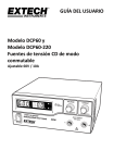
USER GUIDE Model DCP60 and Model DCP60‐220 Switching Mode DC Power Supplies 60V / 10A Adjustable Introduction and Features Thank you for selecting the Extech DCP60 (110V) or DCP60‐220 (220V) Switching Power Supply. The DCP60 is highly efficient, incorporates upgraded SMPS circuitry with small form factor, benefits from an automatic cross‐over for CC and CV, has three (3) Voltage/Current presets, and can be remote controlled. The DCP60 is perfect for solving a variety of loading conditions and applications. Dual action (Course/Fine) tuning provides smooth, accurate, and quick setting of Voltage/Current Setting, changing, and verifying the current limit level is convenient and can be performed without output pole spiking The Remote Control feature permits output ON/OFF and Voltage/Current adjustments The USB port offers PC connectivity for programming and running ramp/soak cycles with 20 programmable sets of Voltage/Current and varying test durations (up to 999 cycles) Applications and industries where the DCP60 can be employed include laboratory, telecommunications, production testing, field testing, DC network powering, and more Three (3) user programmable Voltage/Current settings offer quick recall of frequently used test settings This device is shipped fully tested and calibrated and, with proper use, will provide years of reliable service. Please visit our website (www.extech.com) to check for the latest version of this User Guide, Product Updates, and Customer Support. 2 DCP60‐en‐EU_V1.5 9/14 Safety This manual contains important safety and operation instructions for correct use of the power supply. Read through the manual and pay special attention to the markings and labels of this unit and equipment to be connected. Pay special attention to these two types of notices used in this manual: WARNING : Failure to observe this warning may cause injury to persons and damage to power supply or connected equipment. CAUTION : Failure to observe this warning may result in damage to equipment and improper functioning of the power supply. WARNING 1. 2. 3. 4. 5. 6. 7. Do not use this power supply near water Do not operate or touch this power supply with wet hands Do not open the casing of the power supply when it is connected to ac mains Refer all servicing to qualified service personnel only Before replacing the AC fuse, determine the cause and clear up the cause first Replace the AC fuse with the same type and rating as the original fuse The maximum output voltage of the DCP60 exceeds 60VDC, avoid touching the metal contact parts at the output terminals CAUTION 1. 2. 3. 4. 5. 6. 7. 8. 9. Use a grounded 3 pin AC source This unit is intended for indoor use only Do not operate or place this unit in a humid, dusty location Do not operate this unit in direct sunlight or near any heat source Before plugging into local AC mains, check with the rating label at the back of the unit Do not block any ventilation openings of the unit This unit must be used within the specified rating; regular excessive continuous loading may cause damage to the power supply 2 The gauge size of the input power cable must be at least 0.75mm and the total length of power cable must not exceed 3m Input Fuse Recommended: T3AL250V (3A Time‐Lag) 3 DCP60‐en‐EU_V1.5 9/14 Power Supply Description FRONT PANEL (1) LED panel meter display with CC/CV Indictor (2) Rear Control Indicator (lights when using Preset/ Remote Control/ Set mode) (3) Output Voltage Control Knob (controls both the main and auxiliary output voltage) (4) Output Current Control Knob (controls both the main and auxiliary output current limit) (5) Power ON/OFF Switch (6) Aux. output terminal (max 5A); The total rated current (Aux.+Main) is 10A REAR PANEL (7) Main Output Terminal (Rated for 10A); The total rated current (Aux.+Main) is 10A (8) Mode Selection Switch (Normal, Preset, Remote Control, Set Modes) (9) Recall – Preset Voltage Selection Switch (10) Remote Control Terminal (11) Cooling Fan Air Intake Grille (12) AC Input Plug (13) USB port 4 DCP60‐en‐EU_V1.5 9/14 Control Mode Selections There are four control modes for the power supply: NORMAL, PRESET, SET and REMOTE CONTROL modes. Slide the Mode Selection Switch (8) to the desired Mode. The power supply is factory preset to Normal Mode with maximum current level CC. Normal Mode This is the factory default mode; the power supply output Voltage and Current are controlled by the dual action gain knobs. 1. Push the knobs to toggle the coarse and fine tuning, notice the subtle changes in brightness of the related LED. 2. Adjust the knobs to the desired values using coarse and then fine tuning. 3. To check the preset current level, turn the Current Knob lightly in any direction. 4. The display will resume its normal brightness after a few seconds to re‐affirm the adjustment. Note: The total rated current (Aux.+Main) is 10A 9 Preset Mode 1. 2. 3. 4. 8 In this mode, the Rear Control Light is ON to indicate that the panel V & I controls are de‐activated. There are three preset outputs P1/ P2/ P3 available using the Recall Selection Switch (9) The preset values are factory set as shown in the table below. The user can change these output settings; please refer to the next paragraph. Recall No. P1 P2 P3 Output Voltage 5V 13.8V 55V Output Current Maximum Maximum Maximum Set Mode Enter the Set Mode by pushing Switch (8) to the Set Mode slot; the power supply is now ready to be preset. To define the preset output P1/ P2/ P3 Move the Recall Switch (9) to position P1, P2 or P3 Adjust the front panel voltage control knob to set the desired voltage value Adjust the front panel current control knob to set the desired current limit value Repeat the procedure for the remaining recall locations P1, P2, P3 if desired. Move Mode Switch (8) from Set to Preset position to confirm the settings. Set Mode Notes: All presets are saved after the power supply has been switched off. Always check the output voltage of the Preset before connecting to a Load. To check the preset values: 1. Move the Mode Switch (8) to the Preset position and then set the Recall Switch (9) to P1, P2 or P3. 2. The V and I settings for the corresponding RECALL P1, P2, P3 memories will be shown on the panel meter. 1. 2. 3. 4. 5. 5 DCP60‐en‐EU_V1.5 9/14 Remote Control Mode To control the output voltage and current by remote control connector (10) please refer to the section entitled Remote Control. Reset to Factory Default settings 1. 2. 3. 4. Switch OFF the power supply Push and hold both front panel voltage and current control knobs at the same time Switch ON the power supply again Release the front panel voltage and current control knobs PC Interface Control To control the power supply using the supplied Software, refer to the PC Interface Control Section. 6 DCP60‐en‐EU_V1.5 9/14 Operation Note: The DC60 Max Output Voltage is 60VDC and the total rated current (Aux.+Main) is 10A Powering the Supply Check the rating label of the power supply and ensure that it complies with the AC mains voltage that is to be used. Connect the power supply to the AC Mains using the provided power cord. Ensure that the Mode Switch (8) is set to the Normal Mode position. The Model DCP60 requires a 110VAC power source and the DCP‐220 requires a 220V power source. Switching the Power Supply ON and Self‐Test Information The power supply will perform a series of self‐tests when it is switched on. The LED and other indicators on the front panel will illuminate in sequence. When the cooling fan is being checked, a high speed wind sound can be heard. After the self‐tests, the CV, V and A LED indicators are lit displaying voltage and 0.0 current. To find the CC current level, turn the current control knob one click in either direction. The current display returns to 0.0 after a few seconds. The table below details the self‐test sequence: Self‐test displays Test Software version Segment check C.V. Indicator check C.C. Indicator check Rear control indicator check Return to C.V. Start to check Over voltage protection check Over load protection check Over temperature protection check Fan check Output off (remote control mode) 7 DCP60‐en‐EU_V1.5 9/14 Using the control knobs The rotary encoder control knobs have fine and coarse tuning with ‘clicking’ movement. Push the knobs to toggle between coarse and fine tuning, notice the subtle changes in brightness of the related LED. Adjust the knobs to the desired values by using coarse and then fine tuning. The display will resume its normal brightness after few seconds to confirm an adjustment. Connecting the Power Supply and running a test 1. Connect the equipment under test to the power supply. Red (+) is connected to the positive 2. 3. 4. 5. polarity input of the equipment and Black (‐) is connected to the negative polarity input of the equipment. Switch ON the power supply first; the panel meter & green CV Indicator should illuminate. Next, switch ON the equipment under test; the panel meter & green CV Indicator should remain lit in green. Testing can now begin. When finished, switch OFF the equipment under test first and then switch off the power supply. Setting up the Power supply in Constant Current (CC) mode 1. 2. 3. 4. 5. 6. 7. Set current knob to minimum Set voltage knob to Maximum Short output leads together Turn on the power supply Turn up current knob until you reach the current value you want to use. Turn off the power supply Un‐short the leads 8 DCP60‐en‐EU_V1.5 9/14 Remote Control Operation There are two methods for remotely controlling current and voltage adjustments. Current must be controlled for both methods otherwise the unit will default to CC mode. REMOTE CONTROL – METHOD 1: Using two external DC voltage sources Remote Socket Pin Assignment for external variable voltage source PIN FUNCTIONS REMARKS 1 Internal DC +5V Lower than 50mA 2 Voltage adjust 0 to 5V External VDC 3 Current adjust 0 to 5V External VDC 4 Ground 5 Output OFF Short to ground for OFF 6 N.A. 7 N.A. 8 N.A. Check the output voltage range of the power supply by varying the external voltage source. Short circuit the main output with 10AWG wire to check the CC setting on the display while varying the external voltage source. REMOTE CONTROL – METHOD 2: Using two 0 to 5K Ohm variable resistors Remote Socket Pin Assignment for external variable resistor PIN FUNCTIONS REMARKS 1 Internal DC +5V One end of resistor 2 Voltage adjust Variable leg of resistor 3 Current adjust Variable leg of resistor 4 Ground Other end of resistor 5 Output OFF Short to ground for OFF 6 N.A. 7 N.A. 8 N.A. Check the output voltage range of the power supply by adjusting the 5Kohm variable resistor. Short circuit the main output with 10AWG wire to check the CC setting on the display while adjusting the variable resistor. 9 DCP60‐en‐EU_V1.5 9/14 Remote Control Output ON/OFF Remote output ON/OFF control can be activated in any of the modes Normal, Preset, Set, and Remote. Review the conditions below: By default, Pin 5 is open and the output is ON. Shorting Pin 5 to Pin 4 (ground) switches the output OFF. When the output is OFF, the C.V. & C.C. LEDs will flash. The present output voltage and current setting will be shown on the panel meter. The user can adjust the output using the voltage & current control knob to the desired value when the output is OFF. Remark: Use only the 8‐pin remote plug provided and connect with 22AWG wires. See diagram below. Note: Pin numbers are marked on the black area of the socket 10 DCP60‐en‐EU_V1.5 9/14 PC Software Program Quick Start Software Installation Instructions 1. Create a new folder on the desktop of the PC, which is to be loaded with the DCP60 software. Name the folder DCP60 or any easily distinguishable name. 2. Insert the DCP60 PC Interface Software CD into the CD/DVD drive. When the Auto Play dialog box appears, select “Open folder to view files”. 3. Select all files on the CD and drag/drop or copy them into the folder that was created in Step 1. 4. Close the DCP60 software CD file and remove the CD from the CD/DVD drive. 5. Open the desktop folder created in Step 1, then open the USB CP210x Drivers V6.5 for Win_XP_S2K3_Vista_7 subfolder. 6. Double‐click on the executable file CP210xVCPInstaller.exe from within the USB Drivers folder. 7. Ensure your anti‐virus or network security application is set to permit the execution of the installer file. 8. When the Silicon Labs prompt appears, select Install to load the necessary drivers onto your PC. An older version of the drivers may already reside on your PC; therefore, if prompted to update the drivers, select Yes. 9. Once the drivers have been loaded/updated, restart the PC. 10. After the PC has been restarted, open the desktop folder once more. Open the hcs subfolder and launch the hcs.exe executable file. 11. Connect the Power Supply to the PC via the supplied USB cable. Software Overview The supplied PC software offers three main features: External Timed Programs: Automatic Voltage/Current stepping and program cycling Internal Preset Memory: Three pre‐programmed fixed Voltage/Current presets Datalogging: Automatic recording of voltage and current outputs with programmable sample rate Supported Operating Systems: Windows XP/Vista/7 (32bits/64bits) Driver: Silicon Lab CP210x USB driver (Included in CDROM folder “USB CP210x Drivers V6.5 for Win_XP_S2K3_Vista_7”) Executable Program: run “DCP60\hcs\hcs.exe” 11 DCP60‐en‐EU_V1.5 9/14 Main Interface Display The Main interface is divided into 7 panels. 1. 2. 3. 4. 5. 6. 7. Display panel: Indicates real‐time power supply information. Main Configuration and Datalogger Display panel: Use this panel to adjust general program settings and to view External Timed Programs, Internal Preset Memory data, and Datalogger information. Voltage and Current setting panel: Use this panel to set the output values and to switch the output On/Off. Data handling panel: Use this panel to save, load and print data. External Timed Program Description field: Enter a customized description for an External Timed Sequence. Program running cycle setting panel: Set the desired number of running cycles for the External Timed Sequence. Information panel: Displays the Maximum voltage/ current, Datalogger Sampling time (rate), upper voltage/ current limits, and software version. 12 DCP60‐en‐EU_V1.5 9/14 Display Panel 1. 2. 3. 4. Actual Output Voltage, Current, and Power values C.V./ C.C. Mode status Setting values Output ON/OFF status Output Setting Panel 1. 2. 3. 4. Voltage Output setting Current Output setting Output ON/OFF setting SET (confirm) output values Directly type the value in the Voltage and Current fields or use the slider to set the Voltage and Current values and then press SET to confirm. Click ON or OFF to set the output status. Note: Once the Slider is active, use the keyboard left and right arrow keys to fine adjust the setting. 13 DCP60‐en‐EU_V1.5 9/14 Setting Tab On the ‘Setting’ page, general program settings can be configured as listed below: Select the desired language. Select the PC COM Port number to which the power supply is to be connected. Set the datalogging sampling time (rate) using the slide bar. Set the output voltage upper limit (UVL) value to further safeguard low voltage applications. This sets the limits for all Tabs. Set the output current upper limit (UCL) value to further safeguard low current applications. This sets the limits for all Tabs. Click the DEFAULT button to reset settings to factory default values. Press OK to confirm settings. 14 DCP60‐en‐EU_V1.5 9/14 External Timed Program External Timed Programs are completely PC controlled. The PC automatically changes the Voltage and Current outputs (and their time duration) based on pre‐programmed settings. Click on the EXTERNAL TIMED PROGRAM tab and then double click a cell to set a value. For example (see diagram below), Step 2 Voltage, slide the bar to set the desired output level Once the Slider is active, you can use the keyboard left and right arrow keys to fine adjust the setting. Set the duration for this step as shown in diagram below. The range of time is 0 to 9 hours/59 minutes/59 seconds. Double‐click into the cell and then into the time box. Click on the up/down arrow buttons. If the time is set to ‘0’ the step will be skipped. Set the running cycle (number of times the entire sequence will run) as shown below (range is 0 to 999 cycles). Use the slider or type directly in the field to set the number of cycles. Set the cycle value to ‘0’ to cycle the sequence indefinitely. Click the RUN button to start the cycle. Click the STOP button to stop the cycle. Click the CLEAR TABLE button to clear all settings. Warning: When the Sequence has completed the output settings will revert to the settings displayed on the left side of this window. Make sure you have this set appropriately to prevent damage to your UUT. 15 DCP60‐en‐EU_V1.5 9/14 Internal Preset Memory The PC interface’s remote Preset capability simplifies the tedious process of keying in groups of entries. Since all the data are displayed at the same time on the PC monitor, the possibility of entering data incorrectly is greatly reduced. Data of different groups can be classified, stored, exported and retrieved for use at any time. Retrieved data will appear red in color if they exceed the preset voltage/current limits. Click ‘Clear Table’ to delete all data on the Display Table to prepare for new data. Click ‘Read for PS’ to retrieve data from the Power Supply. 16 DCP60‐en‐EU_V1.5 9/14 Datalogger Window 1. 2. Adjust slider to move the displayed waveform left and right Adjust slider to zoom in and out Note: Once the Slider is active, you can use your keyboard left and right arrow keys to fine adjust your setting. The graphical datalogger window is used to display output Voltage, Current, and Power over time. 17 DCP60‐en‐EU_V1.5 9/14 Save, Load, and Print Data External Timed Program tab The buttons are used to Save and Load an External Timed Program or Print the current settings. If desired, add a description in the Program Description field. Click to save an External Timed Program to a CSV file. Click to open and load settings from a CSV file. Click to print the settings. Internal Preset Memory tab The buttons are used to Save and Load Internal Preset data or Print the current settings. If desired, add a description in the Program Description field. Click to save an Internal Preset Memory set to a CSV file. Click to open and load a setting from CSV file. Click to print a setting. Datalog tab The buttons are used to Save and Load a Datalog file or Print the current settings. If desired, add a description in the Program Description field. Save the data in CSV format for later analysis. Open and load data from CSV document. Print the data. 18 DCP60‐en‐EU_V1.5 9/14 Software Programming Command Set (Protocol) Command line format: COMMAND<parameter1><parameter2>... [CR] Command code & return value Input Command: GMAX[CR] Return value: <voltage><current>[CR] OK[CR] Function Get PS maximum Voltage & Current value <voltage>=??? <current>=??? Input Command: VOLT<voltage>[CR] Return value: OK[CR] Preset Voltage value <voltage>=000<???<Max‐Volt *Max‐Volt value refer to product specification Input Command: CURR<current>[CR] Return value: OK[CR] Preset Current value <current>=000<???<Max‐Curr *Max‐Curr value refer to product specification Input Command: GETS[CR] Return value: <voltage><current>[CR] OK[CR] Get PS preset Voltage & Current value <voltage>=??? <current>=??? Input Command: GETD[CR] Return value: <voltage><current><status>[CR] OK[CR] Get PS Display values of Voltage, Current and Status of CC/CV <voltage>=???? <current>=???? <status>=0/1 (0=CV, 1=CC) Input Command: GOVP[CR] Return value: <voltage>[CR] OK[CR] Get preset upper limit of output Voltage <voltage>=??? Input Command: SOVP<voltage>[CR] Return value: OK[CR] Preset upper limit of output Voltage <voltage>=000<???<Max‐Volt *Max‐Volt value refer to product specification Input Command: Get preset upper limit of output Current 19 Example Input command: GMAX[CR] Return value: 180200[CR] OK[CR] Meaning: Maximum Voltage is 18.0V Maximum Current is 20.0A Input command: VOLT127[CR] Return value: OK[CR] Meaning: Set Voltage value as 12.7V Input command: CURR120[CR] Return value: OK[CR] Meaning: Set Current value as 12.0A Input command: GETS[CR] Return value: 150180[CR] OK[CR] Meaning: The Voltage value set at 15V and Current value set at 18A Input command: GETD[CR] Return value: 150016001[CR] OK[CR] Meaning: The PS Display value is 15V and 16A. It is in CC mode. Input command: GOVP[CR] Return value: 111[CR] OK[CR] Meaning: The preset upper limit of output Voltage is 11.1V Input command: SOVP151[CR] Return value: OK[CR] Meaning: Preset upper limit of output Voltage as 15.1V Input command: DCP60‐en‐EU_V1.5 9/14 GOCP[CR] Return value: <current>[CR] OK[CR] <current>=??? Input Command: SOCP<current>[CR] Return value: OK[CR] Preset upper limit of output Current <current>=000<???<Max‐Curr *Max‐Curr value refer to product specification Input Command: PROM<voltage0><current0> <voltage1><current1> <voltage2><current2>[CR] Return value: OK[CR] Save Voltage and Current value into 3 PS memory locations <voltageX>=??? <currentX>=??? (X is memory location number start from 0 to 2) Input Command: GETM[CR] Return value: <voltage0><current0>[CR] <voltage1><current1>[CR] <voltage2><current2>[CR] OK[CR] Get saved Voltage and Current value from 3 PS memory loctions <voltageX>=??? <currentX>=??? (X is memory location number start from 0 to 2) Input Command: RUNM<memory>[CR] Return value: OK[CR] Set Voltage and Current using values saved in memory locations <memory>=0/1/2 20 GOCP[CR] Return value: 111[CR] OK[CR] Meaning: The preset upper limit of output Current is 11.1A Input command: SOCP151[CR] Return value: OK[CR] Meaning: Preset upper limit of output Current as 15.1A Input command: PROM111111022122033133[CR] Return value: OK[CR] Meaning: Preset Memory 0 as 11.1V and 11.1A Preset Memory 1 as 2.2V and 12.2A Preset Memory 2 as 3.3V and 13.3A Input command: GETM[CR] Return value: 111111[CR] 122122[CR] 133133[CR] OK[CR] Meaning: PS return following preset value from memory locations; Memory 0 is 11.1V and 11.1A Memory 1 is 12.2V and 12.2A Memory 2 is 13.3V and 13.3A Input command: RUNM1[CR] Return value: OK[CR] Meaning: Set Voltage and Current using values saved in memory location 1 DCP60‐en‐EU_V1.5 9/14 Specifications Output Variable Voltage Output 1 to 60VDC Variable Current Output 0 to 10ADC Voltage Regulation Load (10 to 100% Load) 50mV Model DCP60 Line (90 to 130VAC Variation): 20mV Model DCP60‐220 Line (170 to 264VAC Variation): 20mV Current Regulation Load (10 to 90% rated voltage) 100mA 50mA Model DCP60 Line (90 to 130VAC Variation): Model DCP60‐220 Line (170 to 264VAC Variation: 50mA Ripple and Noise Ripple and Noise (RMS) voltage 5mV Ripple and Noise (P‐P) voltage 100mv Current Ripple and Noise (RMS) 10mA Meter Type and Accuracy Voltage Meter 3‐digit LED Display ±0.2% + 3 counts 3‐digit LED Display ±0.2% + 3 counts Current Meter Input Input Voltage Model DCP60: 90 to 130VAC 50/60Hz Model DCP60‐220: 220 to 240CVAC 50/60Hz Fuse 8A/250V 5x20mm (120V); 4A/250V 5x20mm (220V) Full Load Current 6.2A (120V); 3.25A (220V) Installation category CAT 2 Other Efficiency 89% Switching Frequency 65 to 85 kHz (approx.) Tracking Over‐Voltage Protections O/P 1‐5V: set voltage +2V O/P 5‐20V: set voltage +3V O/P 20‐60V: set voltage +4V Transient Response Time (50‐100% load) 1.5ms Power Factor Control Power Factor correction >0.9 at optimal load Cooling method Thermostatic control fan from zero to full speed Protections Overload, Short Circuit by Constant Current, Output Tracking Over Voltage, and Over Temperature Operating %RH 10 to 80% Relative Humidity Approvals CE, EMC: EN 55011, 55022, LVD: EN 60950, 61010 Dimensions 7.9 x 3.5 x 8.5" (200 x 90 x 215mm) Weight 5.7lbs. (2.6 kg) Altitude up to 6561 ft. (2000m) Pollution degree 2 Copyright © 2014 FLIR Systems, Inc. All rights reserved including the right of reproduction in whole or in part in any form www.extech.com 21 DCP60‐en‐EU_V1.5 9/14 Troubleshooting OUP: Over Voltage Protection This unit has a built‐in tracking over voltage protection feature. In the event of output voltage becoming greater than the set value (see specified range from specifications table), protection will be triggered and the output power will be cut off and OUP warning appears as below. To reset the warning, switch off the unit and remove all loading. Switch the unit back on again and it should resume normal operation. If this problem persists, please contact the customer care department or the point of purchase. OTP: Over Temperature Protection There is a thermo sensor inside the unit to monitor and prevent the unit from unduly heating internally. When an OTP error occurs, there is no output and the following warning will appear on the LED display. When this warning appears, switch off the unit and remove all loading. Check the load and output setting. Allow the unit to cool for at least 30 minutes. Check to see if any ventilation holes are blocked, also check that there is sufficient clearance around the power supply. Listen carefully for the short wind sound emanating from the cooling fan when the unit is switched ON again. If the wind sound is not detected, the fan may be faulty; do not use the power supply in this case, contact the customer care department or the agent from the point of purchase. OLP: Over Load Protection Normally the overload protection is sustained by the CC constant current mode. When the CC mode fails and goes undetected, serious damage to the test piece or load may occur. The OLP is used to minimize the extent of damage to the loads in the event of power supply failure. Switch off the power supply as soon as this warning is seen (as shown below). To reset this warning, switch off the unit and remove all loading. Switch the unit back on again and double check with caution. If this problem persists, please contact the customer care department or and consult with the agent at the point of purchase. 22 DCP60‐en‐EU_V1.5 9/14