1
Zlinx Radio Modem
ZP Series
Documentation Number: ZP24D-250RM-SR-0812
pn#7337R4
This product designed and manufactured in Ottawa, Illinois USA
of domestic and imported parts by
707 Dayton Road -- P.O. Box 1040 -- Ottawa, IL 61350 USA
Phone (815) 433-5100 -- General Fax (815) 433-5105
Phone (815) 433-5100 -- General Fax (815) 433-5105
Website: www.bb-elec.com
European Headquarters
B&B Electronics
Westlink Commercial Park -- Oranmore, Co. Galway, Ireland
Phone +353 91-792444 -- Fax +353 91-792445
Website: www.bb-europe.com
B&B Electronics Mfg. Co. Inc. -- June 2008
Manual Documentation Number: ZP24D-250RM-SR-0812
Table of Contents
B&B Electronics Mfg Co Inc – 707 Dayton Rd - PO Box 1040 - Ottawa IL 61350 - Ph 815-433-5100 - Fax 815-433-5104 – www.bb-elec.com
B&B Electronics – Westlink Commercial Park – Oranmore, Galway, Ireland – Ph +353 91-792444 – Fax +353 91-792445 – www.bb-europe.com
This document contains information that is proprietary and confidential to B&B
Electronics Mfg. Co. Inc. The methods described herein are for the exclusive use of
B&B Electronics authorized personnel. Any unauthorized use or dissemination of the
information contained in the document is strictly forbidden.
B&B Electronics Mfg Co Inc – 707 Dayton Rd - PO Box 1040 - Ottawa IL 61350 - Ph 815-433-5100 - Fax 815-433-5104 – www.bb-elec.com
B&B Electronics – Westlink Commercial Park – Oranmore, Galway, Ireland – Ph +353 91-792444 – Fax +353 91-792445 – www.bb-europe.com
Table of Contents
Introduction
1
Hardware Installation
2
DIP SWITCH SETTINGS
MOUNTING AND POWER
SERIAL CONNECTIONS
RS-232
RS-422/485
WIRELESS LINK FAILURE OUTPUT
LED INDICATORS
RADIO FREQUENCY INFORMATION
2
2
3
3
4
5
6
6
Zlinx Manager Software
INSTALLATION
SET UP
ON-LINE CONFIGURATION
TEST / TROUBLESHOOT
FIRMWARE UPDATE
7
7
7
9
13
15
Specifications
16
Advanced Programming
19
SAMPLE CONFIG: MODIFY RF DESTINATION ADDRESS
COMMAND REFERENCE TABLE
COMMAND DESCRIPTIONS
API OPERATION
Manual Documentation Number: ZP24D-250RM-SR-0812
19
20
34
60
Table of Contents
B&B Electronics Mfg Co Inc – 707 Dayton Rd - PO Box 1040 - Ottawa IL 61350 - Ph 815-433-5100 - Fax 815-433-5104 – www.bb-elec.com
B&B Electronics – Westlink Commercial Park – Oranmore, Galway, Ireland – Ph +353 91-792444 – Fax +353 91-792445 – www.bb-europe.com
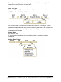
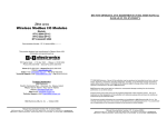
Introduction
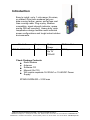
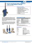
Easy to install, up to 1 mile range. No wires,
no cables! Zlinx radio modems get your
data moving farther, easier, and at less cost
than running cable. Plug-n-play, Modbus
compatible, signal strength indicator, space
saving DIN rail mounting. Heavy-duty, wide
temperature design handles most industrial
power configurations and tough indoor/outdoor
environments.
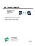
Model #
ZP24D-250RM-SR
Frequency
2.4GHz
Radio
Power
Configurable
Up To
100mW
RF Data Rate
250Kbps
Check Package Contents
Radio Modem
Antenna
Software CD
Manual (On CD)
Will require separate 18-30VAC or 10-48VDC Power
Supply
ZP24D-250RM-SR = 2.0W max
Manual Documentation Number: ZP24D-250RM-SR-0812
1
B&B Electronics Mfg Co Inc – 707 Dayton Rd - PO Box 1040 - Ottawa IL 61350 - Ph 815-433-5100 - Fax 815-433-5104 – www.bb-elec.com
B&B Electronics – Westlink Commercial Park – Oranmore, Galway, Ireland – Ph +353 91-792444 – Fax +353 91-792445 – www.bb-europe.com
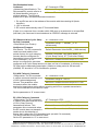
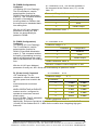
Hardware Installation
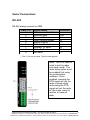
Dip switch Settings
Dipswitch
1
2
3
4
OFF
4-wire
4-wire
No termination
RS-422
ON
2-wire
2-wire
Termination
RS-485
Mounting and Power
Install on properly grounded DIN rail
o Operating Temperature is -40 to 85C
o Operating Humidity is 10-90% non-condensing
Connect Power Supply
o Power supply is 10-48 VDC or 18-30 VAC
10-48 VDC
or
18-30 VAC
2
Manual Documentation Number: ZP24D-250RM-SR-0812
B&B Electronics Mfg Co Inc – 707 Dayton Rd - PO Box 1040 - Ottawa IL 61350 - Ph 815-433-5100 - Fax 815-433-5104 – www.bb-elec.com
B&B Electronics – Westlink Commercial Park – Oranmore, Galway, Ireland – Ph +353 91-792444 – Fax +353 91-792445 – www.bb-europe.com
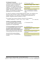
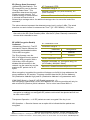
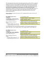
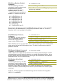
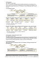
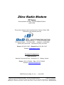
Serial Connections
RS-232
RS-232 always present on DB9
DB9F Pin
1
2
3
4
5
6
7
8
9
Signal Name
Data Carrier Detect*
Receive Data
Transmit Data
Data Terminal Ready
Signal Ground
Data Set Ready*
Request To Send
Clear To Send
Not used
Direction
--Out
In
In
----In
Out
---
* - Pins 1 & 6 are not used. They are tied together
Note: The DTR input is
used to put the radio
into sleep mode. The
radio sleep option must
be enabled first using
the configuration
software. Once
enabled, lowering the
DTR signal will put the
radio in sleep mode
and raising the DTR
signal will put the radio
in idle mode, ready to
receive or transmit
data.
Manual Documentation Number: ZP24D-250RM-SR-0812
3
B&B Electronics Mfg Co Inc – 707 Dayton Rd - PO Box 1040 - Ottawa IL 61350 - Ph 815-433-5100 - Fax 815-433-5104 – www.bb-elec.com
B&B Electronics – Westlink Commercial Park – Oranmore, Galway, Ireland – Ph +353 91-792444 – Fax +353 91-792445 – www.bb-europe.com
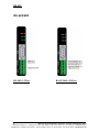
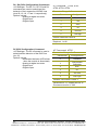
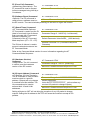
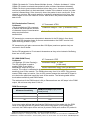
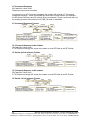
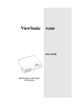
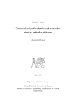
RS-232
RS-422/485
RS-485 (2-Wire)
4
RS-422/485 (4-Wire)
Manual Documentation Number: ZP24D-250RM-SR-0812
B&B Electronics Mfg Co Inc – 707 Dayton Rd - PO Box 1040 - Ottawa IL 61350 - Ph 815-433-5100 - Fax 815-433-5104 – www.bb-elec.com
B&B Electronics – Westlink Commercial Park – Oranmore, Galway, Ireland – Ph +353 91-792444 – Fax +353 91-792445 – www.bb-europe.com
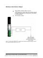
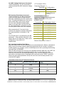
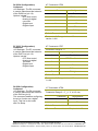
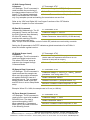
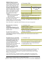
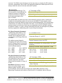
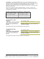
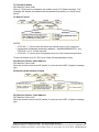
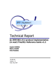
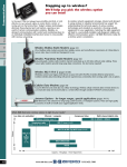
Wireless Link Failure Output
Zlinx Radio modems offer a source
(PNP)transistor output when the wireless signal
strength drops below a critical level (link failure
or miss packets)
40 mA max current
Note: In order for the RSSI LED to continuously indicate the signal strength, set the
RP command (RSSI PWM Timer) to FF.
Manual Documentation Number: ZP24D-250RM-SR-0812
5
B&B Electronics Mfg Co Inc – 707 Dayton Rd - PO Box 1040 - Ottawa IL 61350 - Ph 815-433-5100 - Fax 815-433-5104 – www.bb-elec.com
B&B Electronics – Westlink Commercial Park – Oranmore, Galway, Ireland – Ph +353 91-792444 – Fax +353 91-792445 – www.bb-europe.com
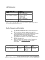
LED Indicators
Front Panel LED
Power
RSSI (Signal Strength)
Wireless Data
Status
Red = ON
OFF = No Power
Green = Strong
Yellow = OK
Red = Weak
OFF = No Signal
Green = Blink ON with
data
Note: In order for the RSSI LED to continuously indicate the signal strength, set the
“RP” command (RSSI PWM Timer) to FF.
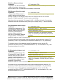
Radio Frequency Information
The ZP24D-250RM-SR has an indoor range up to
300 feet and an outdoor range up to one mile.
These ranges are for line of sight installations using
the supplied antenna. Performance may vary
depending on your particular installation.
The antenna connection on the radio modem is an
RPSMA female plug.
B&B Electronics has a wide variety of accessory
antennas. Visit www.bb-elec.com for more
information.
Model #
ZP24D-250RM-SR
6
Frequency
2.4GHz
Radio
Power
Configurable
Up To
100mW
RF Data
Rate
250Kbps
Manual Documentation Number: ZP24D-250RM-SR-0812
B&B Electronics Mfg Co Inc – 707 Dayton Rd - PO Box 1040 - Ottawa IL 61350 - Ph 815-433-5100 - Fax 815-433-5104 – www.bb-elec.com
B&B Electronics – Westlink Commercial Park – Oranmore, Galway, Ireland – Ph +353 91-792444 – Fax +353 91-792445 – www.bb-europe.com
Zlinx Manager Software
Installation
The Zlinx Manager Software is contained CD.
Insert the CD into the drive.
The installation program should auto start.
Follow the on screen prompts.
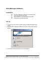
Set Up
1. Connect your PC to the modem using a straight through serial
cable.
2. Start the Zlinx Manage Software and click on the radio modem
button.
3. The radio modem launcher screen will appear
Manual Documentation Number: ZP24D-250RM-SR-0812
7
B&B Electronics Mfg Co Inc – 707 Dayton Rd - PO Box 1040 - Ottawa IL 61350 - Ph 815-433-5100 - Fax 815-433-5104 – www.bb-elec.com
B&B Electronics – Westlink Commercial Park – Oranmore, Galway, Ireland – Ph +353 91-792444 – Fax +353 91-792445 – www.bb-europe.com
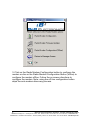
3. Click on the Radio Modem Configuration button to configure the
modem on-line or the Radio Modem Configuration Button (offline) to
configure the modem offline. Follow the on screen directions to
configure the modem. Note: using the off-line configuration button
skips the auto modem discovery process.
8
Manual Documentation Number: ZP24D-250RM-SR-0812
B&B Electronics Mfg Co Inc – 707 Dayton Rd - PO Box 1040 - Ottawa IL 61350 - Ph 815-433-5100 - Fax 815-433-5104 – www.bb-elec.com
B&B Electronics – Westlink Commercial Park – Oranmore, Galway, Ireland – Ph +353 91-792444 – Fax +353 91-792445 – www.bb-europe.com
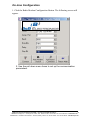
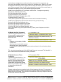
On-Line Configuration
1. Click the Radio Modem Configuration Button. The following screen will
appear.
2. Use the pull down menu items to set up the communication
parameters.
Manual Documentation Number: ZP24D-250RM-SR-0812
9
B&B Electronics Mfg Co Inc – 707 Dayton Rd - PO Box 1040 - Ottawa IL 61350 - Ph 815-433-5100 - Fax 815-433-5104 – www.bb-elec.com
B&B Electronics – Westlink Commercial Park – Oranmore, Galway, Ireland – Ph +353 91-792444 – Fax +353 91-792445 – www.bb-europe.com
3. Click the Auto Modem Search button. The Zlinx Manager
software will find the radio modem. If the modem is not found,
the following screen will appear.
4. When the modem is found, the following screen will appear.
10
Manual Documentation Number: ZP24D-250RM-SR-0812
B&B Electronics Mfg Co Inc – 707 Dayton Rd - PO Box 1040 - Ottawa IL 61350 - Ph 815-433-5100 - Fax 815-433-5104 – www.bb-elec.com
B&B Electronics – Westlink Commercial Park – Oranmore, Galway, Ireland – Ph +353 91-792444 – Fax +353 91-792445 – www.bb-europe.com
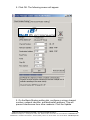
5. Click OK. The following screen will appear.
5. On the Basic Modem setting tab, configure a unique channel
number, network identifier, and destination address. This will
prevent interference from other modems. Click the Update
Manual Documentation Number: ZP24D-250RM-SR-0812
11
B&B Electronics Mfg Co Inc – 707 Dayton Rd - PO Box 1040 - Ottawa IL 61350 - Ph 815-433-5100 - Fax 815-433-5104 – www.bb-elec.com
B&B Electronics – Westlink Commercial Park – Oranmore, Galway, Ireland – Ph +353 91-792444 – Fax +353 91-792445 – www.bb-europe.com
button to save the parameters. Click the Restore Defaults
button to revert to the default configuration.
6. Use the advanced tab to configure additional parameters.
When each option is highlighted, the text box will display an
explanation of the command and the associated hex range.
Click the update button to save the parameters. Click the
Restore Defaults button to revert to the default configuration.
BLANK
12
Manual Documentation Number: ZP24D-250RM-SR-0812
B&B Electronics Mfg Co Inc – 707 Dayton Rd - PO Box 1040 - Ottawa IL 61350 - Ph 815-433-5100 - Fax 815-433-5104 – www.bb-elec.com
B&B Electronics – Westlink Commercial Park – Oranmore, Galway, Ireland – Ph +353 91-792444 – Fax +353 91-792445 – www.bb-europe.com
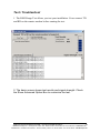
Test / Troubleshoot
1. The RSSI Range Test allows you test your installation. Cross connect TD
and RD on the remote modem before running the test.
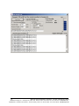
2. The basic screen shows test results and signal strength. Check
the Show Advanced Option Box to customize the test.
Manual Documentation Number: ZP24D-250RM-SR-0812
13
B&B Electronics Mfg Co Inc – 707 Dayton Rd - PO Box 1040 - Ottawa IL 61350 - Ph 815-433-5100 - Fax 815-433-5104 – www.bb-elec.com
B&B Electronics – Westlink Commercial Park – Oranmore, Galway, Ireland – Ph +353 91-792444 – Fax +353 91-792445 – www.bb-europe.com
14
Manual Documentation Number: ZP24D-250RM-SR-0812
B&B Electronics Mfg Co Inc – 707 Dayton Rd - PO Box 1040 - Ottawa IL 61350 - Ph 815-433-5100 - Fax 815-433-5104 – www.bb-elec.com
B&B Electronics – Westlink Commercial Park – Oranmore, Galway, Ireland – Ph +353 91-792444 – Fax +353 91-792445 – www.bb-europe.com
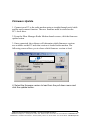
Firmware Update
1. Connect your PC to the radio modem using a straight through serial cable
and the auto connect function. The new firmware must be stored on the
PC’s local drive.
2. From the Zlinx Manager Radio Modem launch screen, click the firmware
update button.
3. Once connected, the software will determine which firmware versions
are available on the PC and what version is loaded in the modem. The
following screen allows you to chose which firmware version to load.
BLANK
BLANK
4. Select the firmware version to load from the pull down menu and
click the update button.
Manual Documentation Number: ZP24D-250RM-SR-0812
15
B&B Electronics Mfg Co Inc – 707 Dayton Rd - PO Box 1040 - Ottawa IL 61350 - Ph 815-433-5100 - Fax 815-433-5104 – www.bb-elec.com
B&B Electronics – Westlink Commercial Park – Oranmore, Galway, Ireland – Ph +353 91-792444 – Fax +353 91-792445 – www.bb-europe.com
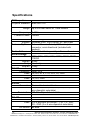
Specifications
RF Properties
Physical Standard
Range
Frequency
Transmit Power
Software
Support
Antenna Options
Radio Address
Serial settings
Baud
Data bit
Parity
Stop bit
IEEE 802.15.4
up to 300 feet indoor or 1 mile outdoor
2.4GHz
100mW
Zlinx Manager
Windows 2000, 2003 Server, XP, and Vista
External Reverse Polarity SMA male jack
connector, omni directional (included with
product)
Defaulted at factory, set by software otherwise
1200, 2400, 4800, 9600, 19200, 38400, 57600,
115200
8 only
None only
1 only
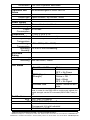
RS-232
Connector
Lines
Connector
Lines
DB9F DCE
TX, RX, RTS, CTS, DTR, RI, GND
Removable terminal block
TX, RX, GND
Connector
Lines
Removable terminal block
2 or 4 wire – TX+, TX-, RX+, RX-, GND (2 or 4
wire dipswitch selectable)
120 Ohm Dipswitch selectable
RS-422
Termination
RS-485
Connector
Lines
SD control
16
Removable terminal block
2 or 4 wire with SD control – TX+, TX-, RX+,
RX-, GND (2 or 4 wire dipswitch selectable)
Bit wise
Manual Documentation Number: ZP24D-250RM-SR-0812
B&B Electronics Mfg Co Inc – 707 Dayton Rd - PO Box 1040 - Ottawa IL 61350 - Ph 815-433-5100 - Fax 815-433-5104 – www.bb-elec.com
B&B Electronics – Westlink Commercial Park – Oranmore, Galway, Ireland – Ph +353 91-792444 – Fax +353 91-792445 – www.bb-europe.com
Termination
Transistor link
failure
Connector
Output type
Power Supply
Connector
Input Voltage
Power
Consumption
Dimensions
Environmental
Operating
Temperature
Storage
Temperature
Operating
Humidity
Enclosure
Rating
Rating
Mounting
120 Ohm Dipswitch selectable
No wireless signal or RSSI LED off
Removable terminal block with RS-422/485
Open collector, dry contact, 40mA
Removable terminal block
10–48VDC, 18-30VAC
2.0W max
1.2W x 3.3D x 4.7H
Intended for indoor use only
-40 to 85ºC (-40 to 185ºF)
-40 to 85ºC (-40 to 185ºF)
10 to 90% non-condensing
IP30
DIN rail mount, 35mm
LED Status
Front Panel LED
Power
RSSI (Signal
Strength)
Wireless Data
Status
Red = On
OFF = No Power
Green = Strong
Yellow = OK
Red = Weak
OFF = No Signal
Green = Blink on with
data
Note: In order for the RSSI LED to continuously indicate the
signal strength, set the RP command (RSSI PWM Timer) to
FF.
Certifications
FCC
CE
FCC Part 15 Class B
CISPR (EN55022) Class B
EN61000-6-1 Generic Standards for Residential,
Commercial, & Light Industrial
EN61000-4-2 ESD
Manual Documentation Number: ZP24D-250RM-SR-0812
17
B&B Electronics Mfg Co Inc – 707 Dayton Rd - PO Box 1040 - Ottawa IL 61350 - Ph 815-433-5100 - Fax 815-433-5104 – www.bb-elec.com
B&B Electronics – Westlink Commercial Park – Oranmore, Galway, Ireland – Ph +353 91-792444 – Fax +353 91-792445 – www.bb-europe.com
UL
18
EN61000-4-3 RFI
EN61000-4-4 EFT
EN61000-4-5 Surge
EN61000-4-6 CI
EN61000-4-8 Power Frequency Magnetic
EN61000-4-11 Voltage Dips & Interruptions
UL, cUL
Manual Documentation Number: ZP24D-250RM-SR-0812
B&B Electronics Mfg Co Inc – 707 Dayton Rd - PO Box 1040 - Ottawa IL 61350 - Ph 815-433-5100 - Fax 815-433-5104 – www.bb-elec.com
B&B Electronics – Westlink Commercial Park – Oranmore, Galway, Ireland – Ph +353 91-792444 – Fax +353 91-792445 – www.bb-europe.com
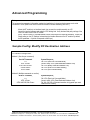
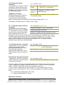
Advanced Programming
Setup
The programming examples in this section require the installation of a hyper terminal program and a serial
connection to a PC. (B&B stocks RS-232 and USB boards to facilitate interfacing with a PC.)
Mount the RF module to an interface board, then connect the module assembly to a PC.
Launch the terminal software and select the 'PC Settings' tab. Verify the baud and parity settings of the
Com Port match those of the RF module.
NOTE: Failure to enter AT Command Mode is most commonly due to baud rate mismatch. Ensure the
„Baud‟ setting on the „PC Settings‟ tab matches the interface data rate of the RF module. By default,
the BD parameter = 3 (which corresponds to 9600 bps).
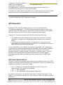
Sample Config: Modify RF Destination Address
„CR‟ stands for carriage return:
Method 1 (One line per command)
Send AT Command
+++
ATDL <Enter>
ATDL1A0D <Enter>
ATWR <Enter>
ATCN <Enter>
System Response_
OK <CR> (Enter into Command Mode)
{current value} <CR> (Read Destination Address Low)
OK <CR> (Modify Destination Address Low)
OK <CR> (Write to non-volatile memory)
OK <CR> (Exit Command Mode)
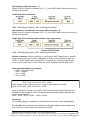
Method 2 (Multiple commands on one line)
Send AT Command_
+++
ATDL <Enter>
ATDL1A0D,WR,CN <Enter>
System Response_
OK <CR> (Enter into Command Mode)
{current value} <CR> (Read Destination Address Low)
OK, OK, OK <CR> (Command execution is triggered upon each
instance of the comma)
Manual Documentation Number: ZP24D-250RM-SR-0812
19
B&B Electronics Mfg Co Inc – 707 Dayton Rd - PO Box 1040 - Ottawa IL 61350 - Ph 815-433-5100 - Fax 815-433-5104 – www.bb-elec.com
B&B Electronics – Westlink Commercial Park – Oranmore, Galway, Ireland – Ph +353 91-792444 – Fax +353 91-792445 – www.bb-europe.com
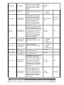
Command Reference Table
Zlinx Radio Modems expect numerical values in hexadecimal. Hexadecimal
values are designated
by a “0x” prefix. Decimal equivalents are designated by a “d” suffix.
Commands are contained
within the following command categories (listed in the order that their
tables appear):
• Special
• Networking & Security
• RF Interfacing
• Sleep (Low Power)
• Serial Interfacing
• I/O Settings
• Diagnostics
• AT Command Options
All modules within a PAN should operate using the same firmware version.
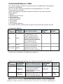
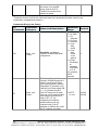
Commands-Special
AT_
Command
Command
_ Category
Name and Description
Parameter
Range
Default
Write. Write parameter values to
non-volatile memory so that
parameter modifications persist
through subsequent power-up or
WR
Special
reset. Note: Once WR is issued, no
additional characters should be sent
to the module until after the
response "OK\r" is received.
Restore Defaults. Restore module
RE
Special
parameters to factory defaults.
Software Reset. Responds
FR ( v1.x80*) Special
immediately with an OK then
performs a hard reset ~100ms later.
*Firmware version in which the command was first introduced (firmware
versions are numbered in hexadecimal notation.)
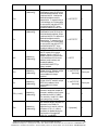
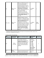
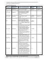
Commands-Networking & Security (Sub categories designated within {brackets})
AT_
Command
Command_
Category
CH
Networking
{Addressing}
ID
Networking
{Addressing}
20
Name and Description
Channel. Set/Read the channel
number used for transmitting and
receiving data between RF
modules (uses 802.15.4 protocol
channel numbers).
PAN ID. Set/Read the PAN
(Personal Area Network) ID._ Use
0xFFFF to broadcast messages
Parameter
Range
Default
0x0B - 0x1A
0x0C - 0x17
0x0C (12d)
0 - 0xFFFF
0x3332_
(13106d)
Manual Documentation Number: ZP24D-250RM-SR-0812
B&B Electronics Mfg Co Inc – 707 Dayton Rd - PO Box 1040 - Ottawa IL 61350 - Ph 815-433-5100 - Fax 815-433-5104 – www.bb-elec.com
B&B Electronics – Westlink Commercial Park – Oranmore, Galway, Ireland – Ph +353 91-792444 – Fax +353 91-792445 – www.bb-europe.com
to all PANs.
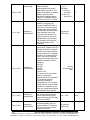
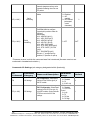
Networking
{Addressing}
DH
Networking
{Addressing}
DL
MY
Networking
{Addressing}
SH
Networking
{Addressing}
SL
Networking
{Addressing}
RR ( v1.xA0*)
Networking
{Addressing}
RN
Networking
{Addressing}
Destination Address High.
Set/Read the upper 32 bits of the
64-bit destination address. When
combined with DL, it defines the
destination address used for
transmission. To transmit using a
16-bit address, set DH parameter
to zero and DL less than 0xFFFF.
0x000000000000FFFF is the
broadcast address for the PAN.
Destination Address Low.
Set/Read the lower 32 bits of the
64-bit destination address. When
combined with DH, DL defines the
destination address used for
transmission. To transmit using a
16-bit address, set DH parameter
to zero and DL less than 0xFFFF.
0x000000000000FFFF is the
broadcast address for the PAN.
16-bit Source Address.Set/Read
the RF module 16-bit source
address. Set MY = 0xFFFF to
disable reception of packets with
16-bit addresses. 64-bit source
address (serial number) and
broadcast address
(0x000000000000FFFF) is
always enabled.
Serial Number High. Read high
32 bits of the RF module's unique
IEEE 64-bit address. 64-bit
source address is always
enabled.
Serial Number Low. Read low
32 bits of the RF module's unique
IEEE 64-bit address. 64-bit
source address is always
enabled.
Retries. Set/Read the maximum
number of retries the module will
execute in addition to the 3 retries
provided by the 802.15.4 MAC.
For each retry, the 802.15.4 MAC
can execute up to 3 retries.
Random Delay Slots. Set/Read
the minimum value of the back-off
exponent in the CSMA-CA
algorithm that is used for collision
avoidance. If RN = 0, collision
avoidance is disabled during the
first iteration of the algorithm
(802.15.4 - macMinBE).
Manual Documentation Number: ZP24D-250RM-SR-0812
0 - 0xFFFFFFFF
0
0 - 0xFFFFFFFF
0
0 - 0xFFFF
0
0 - 0xFFFFFFFF
[read-only]
Factory-set
0 - 0xFFFFFFFF
[read-only]
Factory-set
0-6
0
0 - 3 [exponent]
0
21
B&B Electronics Mfg Co Inc – 707 Dayton Rd - PO Box 1040 - Ottawa IL 61350 - Ph 815-433-5100 - Fax 815-433-5104 – www.bb-elec.com
B&B Electronics – Westlink Commercial Park – Oranmore, Galway, Ireland – Ph +353 91-792444 – Fax +353 91-792445 – www.bb-europe.com
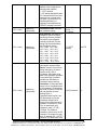
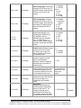
Networking
{Addressing}
MM ( v1.x80*)
NI ( v1.x80*)
Networking
{Identification}
ND ( v1.x80*)
Networking
{Identification}
NT ( v1.xA0*)
Networking
{Identification}
DN ( v1.x80*)
Networking
{Identification}
22
MAC Mode.Set/Read MAC Mode
value. MAC Mode
enables/disables the use of a
B&B header in the 802.15.4 RF
packet. When Mode 0 is enabled
(MM=0), duplicate packet
detection is enabled as well as
certain AT commands. Modes 1
and 2 are strict 802.15.4 modes.
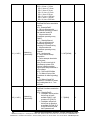
Node Identifier.Stores a string
identifier. The register only
accepts printable ASCII data. A
string can not start with a space.
Carriage return ends command.
Command will automatically end
when maximum bytes for the
string have been entered. This
string is returned as part of the
ND (Node Discover) command.
This identifier is also used with
the DN (Destination Node)
command.
Node Discover.Discovers and
reports all RF modules found. The
following information is reported
for each module discovered (the
example cites use of Transparent
operation (AT command format) refer to the long ND command
description regarding differences
between Transparent and API
operation).
MY<CR>
SH<CR>
SL<CR>
DB<CR>
NI<CR><CR>
The amount of time the module
allows for responses is
determined by the NT parameter.
In Transparent operation,
command completion is
designated by a <CR> (carriage
return). ND also accepts a Node
Identifier as a parameter. In this
case, only a module matching the
supplied identifier will respond.
Node Discover Time.Set/Read
the amount of time a node will
wait for responses from other
nodes when using the ND (Node
Discover) command.
Destination Node. Resolves an
NI (Node Identifier) string to a
physical address. The following
events occur upon successful
command execution:
0–2
0=1=
B&B Mode
1 = 802.15.4
(no ACKs)
2 =802.15.4
(with ACKs)
20-character
ASCII string
0
-
Optional
20-character NI
value
0x01 - 0xFC
0x19
20-character
ASCII string
-
Manual Documentation Number: ZP24D-250RM-SR-0812
B&B Electronics Mfg Co Inc – 707 Dayton Rd - PO Box 1040 - Ottawa IL 61350 - Ph 815-433-5100 - Fax 815-433-5104 – www.bb-elec.com
B&B Electronics – Westlink Commercial Park – Oranmore, Galway, Ireland – Ph +353 91-792444 – Fax +353 91-792445 – www.bb-europe.com
1. DL and DH are set to the
address of the module with the
matching Node Identifier.
2. “OK” is returned.
3. RF module automatically exits
AT Command Mode If there is no
response from a module within
200 msec or a parameter is not
specified (left blank), the
command is terminated and an
“ERROR” message is returned.
CE ( v1.x80*)
Networking
{Association}
SC ( v1.x80*)
Networking
{Association}
SD ( v1.x80*)
Networking
{Association}
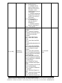
Coordinator Enable. Set/Read
the coordinator setting.
Scan Channels. Set/Read list of
channels to scan for all Active
and Energy Scans as a bitfield.
This affects scans initiated in
command mode (AS, ED) and
during End Device Association
and Coordinator startup:
bit 0 - 0x0B bit 4 - 0x0F
bit 8 - 0x13 bit12 - 0x17
bit 1 - 0x0C bit 5 - 0x10
bit 9 - 0x14 bit13 - 0x18
bit 2 - 0x0D bit 6 - 0x11
bit 10 - 0x15 bit14 - 0x19
bit 3 - 0x0E bit 7 - 0x12
bit 11 - 0x16 bit 15 - 0x1A
Scan Duration. Set/Read the
scan duration exponent. End
Device- Duration of Active Scan
during Association. On beacon
system, set SD = BE of
coordinator. SD must be set at
least to the highest BE parameter
of any Beaconing Coordinator
with which an End Device or
Coordinator wish to discover.
Coordinator- If „ReassignPANID‟
option is set on Coordinator [refer
to A2 parameter], SD determines
the length of time the Coordinator
will scan channels to locate
existing PANs. If
„ReassignChannel‟ option is set,
SD determines how long the
Coordinator will perform an
Energy Scan to determine which
channel it will operate on. „Scan
Time‟ is measured as (# of
channels to scan] * (2 ^ SD) *
15.36ms). The number of
channels to scan is set by the SC
command. The modem can scan
up to 16 channels (SC = 0xFFFF).
Example: The values below show
Manual Documentation Number: ZP24D-250RM-SR-0812
0 - 1 0 = End
Device_ 1 =
Coordinator
0
0 - 0xFFFF
[bitfield]
0x1FFE
0-0x0F [exponent]
4
23
B&B Electronics Mfg Co Inc – 707 Dayton Rd - PO Box 1040 - Ottawa IL 61350 - Ph 815-433-5100 - Fax 815-433-5104 – www.bb-elec.com
B&B Electronics – Westlink Commercial Park – Oranmore, Galway, Ireland – Ph +353 91-792444 – Fax +353 91-792445 – www.bb-europe.com
A1 ( v1.x80*)
Networking
{Association}
A2 ( v1.x80*)
Networking
{Association}
24
results for a 13 channel scan:
If SD = 0, time = 0.18 sec
SD = 8, time = 47.19 sec
SD = 2, time = 0.74 sec
SD = 10, time = 3.15 min
SD = 4, time = 2.95 sec
SD = 12, time = 12.58 min
SD = 6, time = 11.80 sec
SD = 14, time = 50.33 min
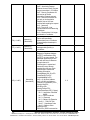
End Device Association.
Set/Read End Device association
options.
bit 0 - ReassignPanID
0 - Will only associate with
Coordinator operating on PAN ID
that matches module ID
1 - May associate with
Coordinator operating on any
PAN ID
bit 1 – ReassignChannel
0 - Will only associate with
Coordinator operating on
matching CH Channel setting
1 - May associate with
Coordinator operating on any
Channel
bit 2 – AutoAssociate
0 - Device will not attempt
Association
1 - Device attempts Association
until success
Note: This bit is used only for
Non-Beacon systems. End
Devices in Beacon-enabled
system must always associate to
a Coordinator
bit 3 – PollCoordOnPinWake
0 - Pin Wake will not poll the
Coordinator for indirect (pending)
data
1 - Pin Wake will send Poll
Request to Coordinator to extract
any pending data bits 4 - 7 are
reserved
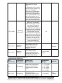
Coordinator Association.
Set/Read Coordinator association
options.
bit 0 – ReassignPanID
0 - Coordinator will not perform
Active Scan to locate
available PAN ID. It will
operate on ID (PAN ID).
1 - Coordinator will perform
Active Scan to determine
an available ID (PAN ID). If
a PAN ID conflict is found,
the ID parameter will
0 - 0x0F [bitfield]
0
0 - 7 [bitfield]
0
Manual Documentation Number: ZP24D-250RM-SR-0812
B&B Electronics Mfg Co Inc – 707 Dayton Rd - PO Box 1040 - Ottawa IL 61350 - Ph 815-433-5100 - Fax 815-433-5104 – www.bb-elec.com
B&B Electronics – Westlink Commercial Park – Oranmore, Galway, Ireland – Ph +353 91-792444 – Fax +353 91-792445 – www.bb-europe.com
AI ( v1.x80*)
Networking
{Association}
change.
bit 1 - ReassignChannel –
0 - Coordinator will not
perform Energy Scan to
determine free channel. It
will operate_ on the
channel determined by the
CH parameter.
1 - Coordinator will perform
Energy Scan to find a free
channel, then operate on
that channel.
bit 2 - AllowAssociation –
0 - Coordinator will not
allow any devices to
associate to it.
1 - Coordinator will allow
devices to associate to it.
bits 3 - 7 are reserved
Association Indication. Read
errors with the last association
request:
0x00 - Successful Completion Coordinator successfully started
or End Device association
complete
0x01 - Active Scan Timeout
0x02 - Active Scan found no
PANs
0x03 - Active Scan found PAN,
but the
CoordinatorAllowAssociation bit is
not set
0x04 - Active Scan found PAN,
but Coordinator and End Device
are not configured to support
beacons
0x05 - Active Scan found PAN,
but the Coordinator ID parameter
does not match the ID parameter
of the End Device
0x06 - Active Scan found PAN,
but the Coordinator CH parameter
does not match the CH parameter
of the End Device
0x07 - Energy Scan Timeout
0x08 - Coordinator start request
failed_
0x09 - Coordinator could not start
due to invalid parameter
0x0A - Coordinator Realignment
is in progress
0x0B - Association Request not
sent
0x0C - Association Request timed
out - no reply was received
0x0D - Association Request had
Manual Documentation Number: ZP24D-250RM-SR-0812
0 - 0x13 [readonly]
-
25
B&B Electronics Mfg Co Inc – 707 Dayton Rd - PO Box 1040 - Ottawa IL 61350 - Ph 815-433-5100 - Fax 815-433-5104 – www.bb-elec.com
B&B Electronics – Westlink Commercial Park – Oranmore, Galway, Ireland – Ph +353 91-792444 – Fax +353 91-792445 – www.bb-europe.com
DA ( v1.x80*)
Networking
{Association}
FP ( v1.x80*)
Networking
{Association}
AS ( v1.x80*)
26
Networking
{Association}
an Invalid Parameter
0x0E - Association Request
Channel Access Failure. Request
was not transmitted - CCA failure
0x0F - Remote Coordinator did
not send an ACK after
Association Request was sent
0x10 - Remote Coordinator did
not reply to the Association
Request, but an ACK was
received after sending the request
0x11 - [reserved]
0x12 - Sync-Loss - Lost
synchronization with a Beaconing
Coordinator
0x13 - Disassociated - No longer
associated to Coordinator
Force Disassociation. End
Device will immediately
disassociate from a Coordinator
(if associated) and reattempt to
associate.
Force Poll. Request indirect
messages being held by a
coordinator.
Active Scan. Send Beacon
Request to Broadcast Address
(0xFFFF) and Broadcast PAN
(0xFFFF) on every channel. The
parameter determines the time
the radio will listen for Beacons
on each channel. A
PanDescriptor is created and
returned for every Beacon
received from the scan. Each
PanDescriptor contains the
following information:
CoordAddress (SH, SL)<CR>
CoordPanID (ID)<CR>
CoordAddrMode <CR>
0x02 = 16-bit Short Address
0x03 = 64-bit Long Address _
Channel (CH parameter) <CR> _
SecurityUse<CR> _
ACLEntry<CR> _
SecurityFailure<CR> _
SuperFrameSpec<CR> (2 bytes):
bit 15 - Association Permitted
(MSB)
bit 14 - PAN Coordinator
bit 13 – Reserved
bit 12 - Battery Life Extension
bits 8-11 - Final CAP Slot
bits 4-7 - Superframe Order
bits 0-3 - Beacon Order
GtsPermit<CR>
RSSI<CR> (RSSI is returned as -
-
-
-
-
0-6
-
Manual Documentation Number: ZP24D-250RM-SR-0812
B&B Electronics Mfg Co Inc – 707 Dayton Rd - PO Box 1040 - Ottawa IL 61350 - Ph 815-433-5100 - Fax 815-433-5104 – www.bb-elec.com
B&B Electronics – Westlink Commercial Park – Oranmore, Galway, Ireland – Ph +353 91-792444 – Fax +353 91-792445 – www.bb-europe.com
dBm)
TimeStamp<CR> (3 bytes)
<CR>
A carriage return <CR> is sent at
the end of the AS command. The
Active Scan is capable of
returning up to 5 PanDescriptors
in a scan. The actual scan time
on each channel is measured as
Time = [(2 ^SD PARAM) * 15.36]
ms. Note the total scan time is
this time multiplied by the number
of channels to be scanned. Also
refer to SD command description.
Energy Scan. Send an Energy
Detect Scan. This parameter
determines the length of scan on
each channel. The maximal
energy on each channel is
returned & each value is followed
by a carriage return. An additional
carriage return is sent at the end
Networking
ED ( v1.x80*)
of the command. The values
0-6
{Association}
returned represent the detected
energy level in units of -dBm. The
actual scan time on each channel
is measured as Time = [(2 ^ED) *
15.36] ms. Note the total scan
time is this time multiplied by the
number of channels to be
scanned (refer to SD parameter).
AES Encryption Enable.
Disable/Enable 128-bit AES
Networking
0
EE ( v1.xA0*)
encryption support. Use in
0-1
{Security}
(disabled)
conjunction with the KY
command.
AES Encryption Key. Set the
128-bit AES (Advanced
Networking
0 - (any 16-Byte
KY ( v1.xA0*)
Encryption Standard) key for
{Security}
value)
encrypting/decrypting data. The
KY register cannot be read.
*Firmware version in which the command was first introduced (firmware versions are
numbered in hexadecimal notation.)
Commands-RF Interfacing
AT_
Command
Command_
Category
Name and
Description
PL
RF Interfacing
Power Level. Select/Read the
power level at which the RF
module transmits conducted
power.
CA (v1.x80*)
RF Interfacing
CCA Threshold. Set/read the
CCA (Clear Channel
Assessment) threshold. Prior to
transmitting a packet, a CCA is
Manual Documentation Number: ZP24D-250RM-SR-0812
Parameter
Range
0-4
0 = -10 / 10 dBm
1 = -6 / 12 dBm
2 = -4 / 14 dBm
3 = -2 / 16 dBm
4 = 0 / 18 dBm
0 - 0x50 [-dBm]
Default
4
0x2C
(-44d dBm)
27
B&B Electronics Mfg Co Inc – 707 Dayton Rd - PO Box 1040 - Ottawa IL 61350 - Ph 815-433-5100 - Fax 815-433-5104 – www.bb-elec.com
B&B Electronics – Westlink Commercial Park – Oranmore, Galway, Ireland – Ph +353 91-792444 – Fax +353 91-792445 – www.bb-europe.com
performed to detect energy on
the channel. If the detected
energy is above the CCA
Threshold, the module will not
transmit the packet.
*Firmware version in which the command was first introduced (firmware versions are
numbered in hexadecimal notation.)
Commands-Sleep (Low Power)
AT_
Command
SM
ST
28
Command_
Category
Name and Description
Parameter
Range
Default
Sleep_ (Low
Power)
Sleep Mode. <NonBeacon
firmware> Set/Read Sleep Mode
configurations.
0–5
0 = No Sleep
1 = Pin
Hibernate
2 = Pin Doze
3 = Reserved
4 = Cyclic
sleep
remote
5 = Cyclic
sleep
remote
�
w/ pin
wake-up
6 = [Sleep
Coordinator]
for
backwards
compatibility
w/ v1.x6
only; otherwise,
use CE
command.
0
Sleep_ (Low
Power)
Time before Sleep.<NonBeacon
firmware> Set/Read time period of
inactivity (no serial or RF data is
sent or received) before activating
Sleep Mode. ST parameter is only
valid with Cyclic Sleep settings (SM
= 4 - 5). Coordinator and End
Device ST values must be equal.
Also note, the GT parameter value
must always be less than the ST
value. (If GT > ST, the
configuration will render the
module unable to enter into
command mode.) If the ST
parameter is modified, also modify
the GT parameter accordingly.
1 -0xFFFF
[x 1 ms]
0x1388
(5000d)
Manual Documentation Number: ZP24D-250RM-SR-0812
B&B Electronics Mfg Co Inc – 707 Dayton Rd - PO Box 1040 - Ottawa IL 61350 - Ph 815-433-5100 - Fax 815-433-5104 – www.bb-elec.com
B&B Electronics – Westlink Commercial Park – Oranmore, Galway, Ireland – Ph +353 91-792444 – Fax +353 91-792445 – www.bb-europe.com
SP
Sleep_ (Low
Power)
DP (1.x80*)
Sleep_ (Low
Power)
Cyclic Sleep Period.<NonBeacon
firmware> Set/Read sleep period
for cyclic sleeping remotes.
Coordinator and End Device SP
values should always be equal. To
send Direct Messages, set SP = 0.
End Device- SP determines the
sleep period for cyclic sleeping
remotes. Maximum sleep period is
268 seconds (0x68B0).
Coordinator- If non-zero, SP
determines the time to hold an
indirect message before discarding
it. A Coordinator will discard
indirect messages after a period of
(2.5 * SP).
Disassociated Cyclic Sleep
Period.<NonBeacon firmware> _
End Device - Set/Read time period
of sleep for cyclic sleeping remotes
that are configured for Association
but are not associated to a
Coordinator. (i.e. If a device is
configured to associate, configured
as a Cyclic Sleep remote, but does
not find a Coordinator, it will sleep
for DP time before reattempting
association.) Maximum sleep
period is 268 seconds (0x68B0).
DP should be > 0 for NonBeacon
systems.
0 - 0x68B0 [x
10 ms]
0
1 - 0x68B0 [x
10 ms]
0x3E8_
(1000d)
*Firmware version in which the command was first introduced (firmware versions are
numbered in hexadecimal notation.)
Commands-Serial Interfacing
AT_
Command
BD
RO
Command_
Category
Serial _
Interfacing
Serial _
Interfacing
Name and Description
Interface Data Rate. Set/Read the
serial interface data rate for
communications between the RF
module serial port and host.
Request non-standard baud rates
with values above 0x80 using a
terminal window. Read the BD
register to find actual baud rate
achieved.
Packetization Timeout. Set/Read
number of character times of intercharacter delay required before
Manual Documentation Number: ZP24D-250RM-SR-0812
Parameter
Range
0 - 7 (standard
baud rates)
0 = 1200 bps
1 = 2400
2 = 4800
3 = 9600
4 = 19200
5 = 38400
6 = 57600
7 = 115200
0x80 - 0x1C200
(non-standard
baud rates)
0 - 0xFF
[x character
times]
Default
3
3
29
B&B Electronics Mfg Co Inc – 707 Dayton Rd - PO Box 1040 - Ottawa IL 61350 - Ph 815-433-5100 - Fax 815-433-5104 – www.bb-elec.com
B&B Electronics – Westlink Commercial Park – Oranmore, Galway, Ireland – Ph +353 91-792444 – Fax +353 91-792445 – www.bb-europe.com
transmission. Set to zero to
transmit characters as they arrive
instead of buffering them into one
RF packet.
API Enable. Disable/Enable API
Mode.
AP (v1.x80*)
PR (v1.x80*)
Serial _
Interfacing
Serial _
Interfacing
Pull-up Resistor Enable.
Set/Read bitfield to configure
internal pull-up resistor status for
I/O lines
Bitfield Map:
bit 0 - AD4/DIO4 (pin11)
bit 1 - AD3 / DIO3 (pin17)
bit 2 - AD2/DIO2 (pin18)
bit 3 - AD1/DIO1 (pin19)
bit 4 - AD0 / DIO0 (pin20)
bit 5 - RTS / AD6 / DIO6 (pin16)
bit 6 - DTR / SLEEP_RQ / DI8
(pin9)
bit 7 - DIN/CONFIG (pin3)
Bit set to “1” specifies pull-up
enabled; “0” specifies no pull-up
0-2
0 = Disabled
1 = API
enabled
2 = API enabled
(w/escaped
control
characters)
0 - 0xFF
0
0xFF
*Firmware version in which the command was first introduced (firmware versions are
numbered in hexadecimal notation.)
Commands-I/O Settings (sub category designated within {brackets})
AT_
Command
Command_
Category
Name and Description
D8
I/O Settings
DI8 Configuration. Select/Read
options for the DI8 line (pin 9) of
the RF module.
I/O Settings
DIO7 Configuration. Select/Read
settings for the DIO7 line (pin 12)
of the RF module. Options include
CTS flow control and I/O line
settings.
D7 (v1.x80*)
30
Parameter
Range
0–1
0 = Disabled
3 = DI
(1,2,4 & 5 n/a)
0–1
0 = Disabled
1 = CTS Flow
Control
2 = (n/a)
3 = DI
4 = DO low
5 = DO high
Default
0
1
Manual Documentation Number: ZP24D-250RM-SR-0812
B&B Electronics Mfg Co Inc – 707 Dayton Rd - PO Box 1040 - Ottawa IL 61350 - Ph 815-433-5100 - Fax 815-433-5104 – www.bb-elec.com
B&B Electronics – Westlink Commercial Park – Oranmore, Galway, Ireland – Ph +353 91-792444 – Fax +353 91-792445 – www.bb-europe.com
D6 (v1.x80*)
D5 (v1.x80*)
I/O Settings
DIO6 Configuration. Select/Read
settings for the DIO6 line (pin 16)
of the RF module. Options include
RTS flow control and I/O line
settings.
I/O Settings
DIO5 Configuration. Configure
settings for the DIO5 line (pin 15)
of the RF module. Options include
Associated LED indicator (blinks
when associated) and I/O line
settings.
D0 - D4
(v1.xA0*)
I/O Settings
IU (v1.xA0*)
I/O Settings
IT (v1.xA0*)
I/O Settings
IS (v1.xA0*)
I/O Settings
IO (v1.xA0*)
I/O Settings
IC (v1.xA0*)
I/O Settings
(DIO4 -DIO4) Configuration.
Select/Read settings for the
following lines: AD0/DIO0 (pin
20), AD1/DIO1 (pin 19),
AD2/DIO2 (pin 18), AD3/DIO3
(pin 17), AD4/DIO4 (pin 11).
Options include: Analog-to-digital
converter, Digital Input and Digital
Output.
I/O Output
Enable.Disables/Enables I/O data
received to be sent out UART.
The data is sent using an API
frame regardless of the current
AP parameter value.
Samples before TX.Set/Read the
number of samples to collect
before transmitting data.
Maximum number of samples is
dependent upon the number of
enabled inputs.
Force Sample.Force a read of all
enabled inputs (DI or ADC). Data
is returned through the UART. If
no inputs are defined (DI or ADC),
this command will return error.
Digital Output Level.Set digital
output level to allow DIO lines that
are setup as outputs to be
changed through Command
Mode.
DIO Change
Detect.Enables/Disables the
monitoring of the change detect
feature on DIO lines 0-7. If a
change is detected, data is
transmitted with DIO data only.
Any samples queued and waiting
for transmission will be sent first.
Manual Documentation Number: ZP24D-250RM-SR-0812
0–1
0 = Disabled
1 = RTS flow
control
2 = (n/a)
3 = DI
4 = DO low
5 = DO high
0–1
0 = Disabled
1 = Associated
indicator
2 = ADC
3 = DI
4 = DO low
5 = DO high
0–1
0 = Disabled
1 = (n/a)
2 = ADC
3 = DI
4 = DO low
5 = DO high
0
1
0
0–1
0 = Disabled
1 = Enabled
1
1 - 0xFF
1
8-bit bitmap (each
bit represents the
level of an I/O line
setup as an
output)
-
-
-
0 - 0xFF [bitfield]
0
(disabled)
31
B&B Electronics Mfg Co Inc – 707 Dayton Rd - PO Box 1040 - Ottawa IL 61350 - Ph 815-433-5100 - Fax 815-433-5104 – www.bb-elec.com
B&B Electronics – Westlink Commercial Park – Oranmore, Galway, Ireland – Ph +353 91-792444 – Fax +353 91-792445 – www.bb-europe.com
Sample Rate. Set/Read sample
rate. When set, this parameter
causes the module to sample all
enabled inputs at a specified
interval.
ADC Voltage Reference.
Set/Read ADC reference voltage
switch.
I/O Input Address. Set/Read
addresses of module to which
outputs are bound. Setting all
bytes to 0xFF will not allow any
received I/O packet to change
outputs. Setting address to
0xFFFF will allow any received
I/O packet to change outputs.
(D0 - D7) Output Timeout.
Set/Read Output timeout values
for lines that correspond with the
D0 - D7 parameters. When output
is set (due to I/O line passing) to
a non-default level, a timer is
started which when expired will
set the output to it default level.
The timer is reset when a valid
I/O packet is received.
IR (v1.xA0*)
I/O Settings
AV (v1.xA0*)
I/O Settings
IA (v1.xA0*)
I/O Settings {I/O
Line Passing}
T0 - T7
(v1.xA0*)
I/O Settings {I/O
Line Passing}
P0
I/O Settings {I/O
Line Passing}
PWM0 Configuration.
Select/Read function for PWM0
pin.
P1 (v1.xA0*)
I/O Settings {I/O
Line Passing}
PWM1 Configuration.
Select/Read function for PWM1
pin.
M0 (v1.xA0*)
I/O Settings {I/O
Line Passing}
PWM0 Output Level. Set/Read
the PWM0 output level.
M1 (v1.xA0*)
I/O Settings {I/O
Line Passing}
PT (v1.xA0*)
I/O Settings {I/O
Line Passing}
RP
I/O Settings {I/O
Line Passing}
PWM1 Output Level. Set/Read
the PWM0 output level.
PWM Output Timeout. Set/Read
output timeout value for both
PWM outputs. When PWM is set
to a non-zero value: Due to I/O
line passing, a time is started
which when expired will set the
PWM output to zero. The timer is
reset when a valid I/O packet is
received.]
RSSI PWM Timer.Set/Read
PWM timer register. Set the
duration of PWM (pulse width
modulation) signal output on the
RSSI pin. The signal duty cycle is
updated with each received
packet and is shut off when the
timer expires.]
32
0 -0xFFFF [x 1
msec]
0
0–1
0 = VREF pin
1 = Internal
0
00xFFFFFFFFFFFF
FFFF
0xFFFFFF
F
FFFFFFFF
F
0 - 0xFF
[x 100 ms]
0xFF
0–2
0 = Disabled
1 = RSSI
2 = PWM Output
0–2
0 = Disabled
1 = RSSI
2 = PWM Output
1
0
0 - 0x03FF
-
0 - 0x03FF
-
0 - 0xFF
[x 100 ms]
0xFF
0 - 0xFF
[x 100 ms]
0x28 (40d)
Manual Documentation Number: ZP24D-250RM-SR-0812
B&B Electronics Mfg Co Inc – 707 Dayton Rd - PO Box 1040 - Ottawa IL 61350 - Ph 815-433-5100 - Fax 815-433-5104 – www.bb-elec.com
B&B Electronics – Westlink Commercial Park – Oranmore, Galway, Ireland – Ph +353 91-792444 – Fax +353 91-792445 – www.bb-europe.com
*Firmware version in which the command was first introduced (firmware versions are
numbered in hexadecimal notation.)
Commands-Diagnostics
AT_
Command
Command_
Category
VR
Diagnostics
VL (v1.x80*)
Diagnostics
HV (v1.x80*)
Diagnostics
DB
Diagnostics
EC (v1.x80*)
Diagnostics
EA (v1.x80*)
Diagnostics
ED (v1.x80*)
Diagnostics
Name and Description
Firmware Version. Read firmware
version of the RF module.
Firmware Version - Verbose.
Read detailed version information
(including application build date,
MAC, PHY and bootloader
versions).
Hardware Version. Read
hardware version of the RF
module.
Received Signal Strength. Read
signal level [in dB] of last good
packet received (RSSI). Absolute
value is reported. (For example:
0x58 = -88 dBm) Reported value is
accurate between -40 dBm and RX
sensitivity.
CCA Failures.Reset/Read count of
CCA (Clear Channel Assessment)
failures. This parameter value
increments when the module does
not transmit a packet because it
detected energy above the CCA
threshold level set with CA
command. This count saturates at
its maximum value. Set count to “0”
to reset count.
ACK Failures. Reset/Read count
of acknowledgment failures. This
parameter value increments when
the module expires its transmission
retries without receiving an ACK on
a packet transmission. This count
saturates at its maximum value.
Set the parameter to “0” to reset
count.
Energy Scan. Send „Energy
Detect Scan‟. ED parameter
determines the length of scan on
each channel. The maximal energy
on each channel is returned and
each value is followed by a
carriage return. Values returned
represent detected energy levels in
units of -dBm. Actual scan time on
each channel is measured as Time
= [(2 ^ SD) * 15.36] ms. Total scan
time is this time multiplied by the
number of channels to be scanned.
Manual Documentation Number: ZP24D-250RM-SR-0812
Parameter
Range
0 - 0xFFFF
[read-only]
Default
Factory-set
-
-
0 - 0xFFFF
[read-only]
Factory-set
0 - 0x64
[read-only]
-
0 - 0xFFFF
-
0 - 0xFFFF
-
0-6
-
33
B&B Electronics Mfg Co Inc – 707 Dayton Rd - PO Box 1040 - Ottawa IL 61350 - Ph 815-433-5100 - Fax 815-433-5104 – www.bb-elec.com
B&B Electronics – Westlink Commercial Park – Oranmore, Galway, Ireland – Ph +353 91-792444 – Fax +353 91-792445 – www.bb-europe.com
*Firmware version in which the command was first introduced (firmware versions are
numbered in hexadecimal notation.)
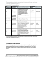
Commands-AT Command Options
AT_
Command
Command_
Category
CT
AT Command
Mode Options
CN
AT Command
Mode Options
AC (v1.xA0*)
AT Command
Mode Options
GT
AT Command
Mode Options
CC
AT Command
Mode Options
Name and Description
Command Mode
Timeout.Set/Read the period of
inactivity (no valid commands
received) after which the RF
module automatically exits AT
Command Mode and returns to
Idle Mode.
Exit Command Mode. Explicitly
exit the module from AT Command
Mode.
Apply Changes. Explicitly apply
changes to queued parameter
value(s) and re-initialize module.
Guard Times. Set required period
of silence before and after the
Command Sequence Characters of
the AT Command Mode Sequence
(GT+ CC + GT). The period of
silence is used to prevent
inadvertent entrance into AT
Command Mode.
Command Sequence Character.
Set/Read the ASCII character
value to be used between Guard
Times of the AT Command Mode
Sequence (GT+CC+GT). The AT
Command Mode Sequence enters
the RF module into AT Command
Mode.
Parameter
Range
Default
2 - 0xFFFF
[x 100 ms]
0x64 (100d)
--
--
--
--
2 - 0x0CE4
[x 1 ms]
0x3E8
(1000d)
0 - 0xFF
0x2B
(„+‟ ASCII)
*Firmware version in which the command was first introduced (firmware versions are
numbered in hexadecimal notation.)
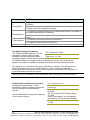
Command Descriptions
Command descriptions in this section are listed alphabetically. Command categories
are designated within "< >" symbols that follow each command title. Zlinx Radio
Modems expect parameter values in hexadecimal (designated by the "0x" prefix).
All modules operating within the same network should contain the same firmware
version.
34
Manual Documentation Number: ZP24D-250RM-SR-0812
B&B Electronics Mfg Co Inc – 707 Dayton Rd - PO Box 1040 - Ottawa IL 61350 - Ph 815-433-5100 - Fax 815-433-5104 – www.bb-elec.com
B&B Electronics – Westlink Commercial Park – Oranmore, Galway, Ireland – Ph +353 91-792444 – Fax +353 91-792445 – www.bb-europe.com
A1 (End Device Association) Command
<Networking {Association}> The A1
command is used to set and read
association options for an End Device.
Use the table below to determine End
Device
behavior in relation to the A1 parameter.
Bit number
0 - ReassignPanID
1 - ReassignChannel
AT Command: ATA1
Parameter Range: 0 - 0x0F [bitfield]
Default Parameter Value: 0
Related Commands: ID (PAN ID), NI
(Node Identifier), CH (Channel), CE
(Coordinator Enable), A2 (Coordinator
Association)
Minimum Firmware Version Required:
v1.x80
End Device Association Option
0 - Will only associate with Coordinator operating on PAN ID that matches Node
Identifier
1 - May associate with Coordinator operating on any PAN ID
0 - Will only associate with Coordinator operating on Channel that matches CH setting
1 - May associate with Coordinator operating on any Channel
0 - Device will not attempt Association
2 - AutoAssociate
1 - Device attempts Association until success_ Note: This bit is used only for NonBeacon systems. End Devices in a Beaconing system must always associate to a
Coordinator
3PollCoordOnPinWake
0 - Pin Wake will not poll the Coordinator for pending (indirect) Data
4-7
[reserved]
1 - Pin Wake will send Poll Request to Coordinator to extract any pending data
A2 (Coordinator Association) Command
<Networking {Association}> The A2
command is used to set and read association
options of the Coordinator.
Use the table below to determine
Coordinator
behavior in relation to the A2 parameter.
AT Command: ATA2
Parameter Range: 0 - 7 [bitfield]
Default Parameter Value: 0
Related Commands: ID (PAN ID),
NI (Node Identifier), CH (Channel),
CE (Coordinator Enable), A1 (End
Device Association), AS Active
Scan), ED (Energy Scan)
Minimum Firmware Version
Required: v1.x80
Manual Documentation Number: ZP24D-250RM-SR-0812
35
B&B Electronics Mfg Co Inc – 707 Dayton Rd - PO Box 1040 - Ottawa IL 61350 - Ph 815-433-5100 - Fax 815-433-5104 – www.bb-elec.com
B&B Electronics – Westlink Commercial Park – Oranmore, Galway, Ireland – Ph +353 91-792444 – Fax +353 91-792445 – www.bb-europe.com
Bit number
0ReassignPanID
1ReassignChannel
2 -AllowAssociate
3-7
End Device Association Option
0 - Coordinator will not perform Active Scan to locate available PAN ID. It will operate on
ID (PAN ID).
1 - Coordinator will perform Active Scan to determine an available ID (PAN ID). If a PAN
ID conflict is found, the ID parameter will change.
0 - Coordinator will not perform Energy Scan to determine free channel. It will operate on
the channel determined by the CH parameter.
1 - Coordinator will perform Energy Scan to find a free channel, then operate on that
channel.
0 - Coordinator will not allow any devices to associate to it.
1 - Coordinator will allow devices to associate to it.
[reserved]
AC (Apply Changes) Command
AT Command: ATAC
<AT Command Mode Options> The AC
Minimum Firmware Version
command is used to explicitly apply
Required: v1.xA0
changes to module parameter values.
„Applying changes‟ means that the module is
re-initialized based on changes made to its parameter values. Once changes are
applied, the module immediately operates according to the new parameter values.
This behavior is in contrast to issuing the WR (Write) command. The WR command
saves parameter values to non-volatile memory, but the module still operates
according to previously saved values until the module is re-booted or the CN (Exit AT
Command Mode) command is issued.
Refer to the “AT Command - Queue Parameter Value” API type for more information.
AI (Association Indication) Command
<Networking {Association}> The AI
command is used to indicate occurrences
of errors during the last association
request.
Use the table below to determine meaning
of the returned values.
36
AT Command: ATAI
Parameter Range: 0 - 0x13
[read-only]
Related Commands: AS (Active Scan),
ID (PAN
ID), CH (Channel), ED (Energy Scan),
A1 (End
Device Association), A2 (Coordinator
Association), CE (Coordinator Enable)
Minimum Firmware Version Required:
v1.x80
Manual Documentation Number: ZP24D-250RM-SR-0812
B&B Electronics Mfg Co Inc – 707 Dayton Rd - PO Box 1040 - Ottawa IL 61350 - Ph 815-433-5100 - Fax 815-433-5104 – www.bb-elec.com
B&B Electronics – Westlink Commercial Park – Oranmore, Galway, Ireland – Ph +353 91-792444 – Fax +353 91-792445 – www.bb-europe.com
Returned
Value
(Hex)
0x00
0x01
0x02
0x03
0x04
0x05
0x06
0x07
0x08
0x09
0x0A
0x0B
0x0C
0x0D
0x0E
0x0F
0x10
0x11
0x12
0x13
Association Indication
Successful Completion - Coordinator successfully started or End Device association
complete
Active Scan Timeout
Active Scan found no PANs
Active Scan found PAN, but the Coordinator Allow Association bit is not set
Active Scan found PAN, but Coordinator and End Device are not configured to support
beacons
Active Scan found PAN, but Coordinator ID (PAN ID) value does not match the ID of the End
Device
Active Scan found PAN, but Coordinator CH (Channel) value does not match the CH of the
End Device
Energy Scan Timeout
Coordinator start request failed
Coordinator could not start due to Invalid Parameter
Coordinator Realignment is in progress
Association Request not sent
Association Request timed out - no reply was received
Association Request had an Invalid Parameter
Association Request Channel Access Failure - Request was not transmitted - CCA failure
Remote Coordinator did not send an ACK after Association Request was sent
Remote Coordinator did not reply to the Association Request, but an ACK was received _
after sending the request
[reserved]
Sync-Loss - Lost synchronization with a Beaconing Coordinator
Disassociated - No longer associated to Coordinator
AP (API Enable) Command
<Serial Interfacing> The AP command is
used to
enable the RF module to operate using a
framebased
API instead of using the default
Transparent
(UART) mode.
AT Command: ATAP
Parameter Range:0 - 2
Parameter
Configuration
0
Disabled (Transparent
operation)
1
API enabled
2
API enabled (with
escaped characters)
Default Parameter Value:0
Minimum Firmware Version Required:
v1.x80
Refer to the API Operation section when API operation is enabled
(AP = 1 or 2).
Manual Documentation Number: ZP24D-250RM-SR-0812
37
B&B Electronics Mfg Co Inc – 707 Dayton Rd - PO Box 1040 - Ottawa IL 61350 - Ph 815-433-5100 - Fax 815-433-5104 – www.bb-elec.com
B&B Electronics – Westlink Commercial Park – Oranmore, Galway, Ireland – Ph +353 91-792444 – Fax +353 91-792445 – www.bb-europe.com
AS (Active Scan) Command
AT Command: ATAS
<AT Command Mode Options> The AS
command is used to send a Beacon
Parameter Range: 0 - 6
Request to a Broadcast
Related Command: SD (Scan
Address (0xFFFF) and Broadcast PAN
Duration), DL (Destination Low
(0xFFFF) on every channel. The
Address), DH (Destination High
parameter determines the amount of time
Address), ID (PAN ID), CH (Channel)
the RF module will listen for Beacons on
Minimum Firmware Version Required:
each channel. A „PanDescriptor‟ is created
v1.x80
and returned for every Beacon received
from the scan. Each PanDescriptor contains the following
information:
CoordAddress (SH + SL parameters)<CR>
CoordPanID (ID parameter)<CR>
CoordAddrMode <CR>
0x02 = 16-bit Short Address
0x03 = 64-bit Long Address
Channel (CH parameter) <CR>
SecurityUse<CR>
ACLEntry<CR>
SecurityFailure<CR>
SuperFrameSpec<CR> (2 bytes):
bit 15 - Association Permitted (MSB)
bit 14 - PAN Coordinator
bit 13 - Reserved
bit 12 - Battery Life Extension
bits 8-11 - Final CAP Slot
bits 4-7 - Superframe Order
bits 0-3 - Beacon Order
GtsPermit<CR>
RSSI<CR> (- RSSI is returned as -dBm)
TimeStamp<CR> (3 bytes)
<CR> (A carriage return <CR> is sent at the end of the AS command.
The Active Scan is capable of returning up to 5 PanDescriptors in a scan. The actual
scan time on each channel is measured as Time = [(2 ^ (SD Parameter)) * 15.36] ms.
Total scan time is this time multiplied by the number of channels to be scanned.
NOTE: Refer the scan table in the SD description to determine scan times. If using API
Mode, no <CR>‟s are returned in the response. Refer to the API Mode Operation
section.
38
Manual Documentation Number: ZP24D-250RM-SR-0812
B&B Electronics Mfg Co Inc – 707 Dayton Rd - PO Box 1040 - Ottawa IL 61350 - Ph 815-433-5100 - Fax 815-433-5104 – www.bb-elec.com
B&B Electronics – Westlink Commercial Park – Oranmore, Galway, Ireland – Ph +353 91-792444 – Fax +353 91-792445 – www.bb-europe.com
AV (ADC Voltage Reference) Command
<Serial Interfacing> The AV command is
used to set/read the ADC reference voltage
switch.
AT Command: ATAV
Parameter Range:0 - 1
Parameter
Configuration
0
BD (Interface Data Rate) Command
<Serial Interfacing> The BD command is
used to set and read the serial interface
data rate usedbetween the RF module and
host. This parameterdetermines the rate at
which serial data is sent to the module
from the host. Modified interface data
rates do not take effect until the CN (Exit
AT Command Mode) command is issued
and the system returns the 'OK' response.
When parameters 0-7 are sent to the
module, the respective interface data rates
are used (as shown in the table on the
right).
The RF data rate is not affected by the BD
parameter. If the interface data rate is set
higher than the RF data rate, a flow control
configuration may need to be
implemented.
VREF Pin
Internal (on1
board reference
- VCC)
Default
Parameter
Value:0
AT Command: ATBD
Minimum Firmware
Version
Parameter
Range:0
- 7 (standard
Required:
v1.xA0
rates)_
0x80-0x1C200
(nonstndard rates)
Parameter Configuration (bps)
0
1200
1
2400
2
4800
3
9600
4
19200
5
38400
6
57600
7
115200
Default Parameter Value:3
Non-standard Interface Data Rates:
Any value above 0x07 will be interpreted as an actual baud rate. When a value above
0x07 is sent, the closest interface data rate represented by the number is stored in
the BD register. For example, a rate of 19200 bps can be set by sending the following
command line "ATBD4B00".
When the BD command is sent with a non-standard interface data rate, the UART will
adjust to accommodate the requested interface rate. In most cases, the clock
resolution will cause the stored BD parameter to vary from the parameter that was
sent (refer to the table below). Reading the BD command (send "ATBD" command
without an associated parameter value) will return the value actually stored in the
module‟s BD register.
Parameters Sent Versus Parameters Stored
BD Parameter Sent
(HEX)
0
Interface Data Rate (bps)
1200
BD Parameter Stored
(HEX)
0
4
19,200
4
7
115,200
7
12C
300
12B
1C200
115,200
1B207
Manual Documentation Number: ZP24D-250RM-SR-0812
39
B&B Electronics Mfg Co Inc – 707 Dayton Rd - PO Box 1040 - Ottawa IL 61350 - Ph 815-433-5100 - Fax 815-433-5104 – www.bb-elec.com
B&B Electronics – Westlink Commercial Park – Oranmore, Galway, Ireland – Ph +353 91-792444 – Fax +353 91-792445 – www.bb-europe.com
CA (CCA Threshold) Command
<RF Interfacing> CA command is used to
set and read CCA (Clear Channel
Assessment) thresholds.
AT Command: ATCA
Parameter Range: 0 - 0x50 [dBm]
Prior to transmitting a packet, a CCA is
performed to detect energy on the transmit
channel. If the detected energy is above
the CCA Threshold, the RF module will not
transmit the packet.
Minimum Firmware Version
Required: v1.x80
Default Parameter Value: 0x2C
�(-44 decimal dBm)
CC (Command Sequence Character)
Command
AT Command: ATCC
<AT Command Mode Options> The
CC command is used to set and read
the ASCII character used between
Default Parameter Value: 0x2B (ASCII
“+”)
Parameter Range: 0 - 0xFF
Related Command: GT (Guard Times)
guard times of the AT Command Mode
Sequence (GT + CC + GT). This sequence enters the RF module into AT Command
Mode so that data entering the module from the host is recognized as commands
instead of payload.
The AT Command Sequence is explained further in the AT Command Mode section.
CE (Coordinator Enable) Command
<Serial Interfacing> The CE command is
used to set and read the behavior (End
Device vs. Coordinator) of the RF module.
AT Command: ATCE
Parameter Range:0 - 1
Parameter
Configuration
0
End Device
1
Coordinator
Default Parameter Value:0
Minimum Firmware Version Required:
v1.x80
40
Manual Documentation Number: ZP24D-250RM-SR-0812
B&B Electronics Mfg Co Inc – 707 Dayton Rd - PO Box 1040 - Ottawa IL 61350 - Ph 815-433-5100 - Fax 815-433-5104 – www.bb-elec.com
B&B Electronics – Westlink Commercial Park – Oranmore, Galway, Ireland – Ph +353 91-792444 – Fax +353 91-792445 – www.bb-europe.com
CH (Channel) Command
<Networking {Addressing}> The CH
command is used to set/read the
operating channel on which RF
connections are made between RF
modules. The channel is one of three
addressing options available to the
module. The other options are the
PAN ID (ID command) and destination
addresses (DL & DH commands).
AT Command: ATCH
Parameter Range: 0x0B - 0x1A
Default Parameter Value: 0x0C
(12 decimal)
Related Commands: ID (PAN
ID), DL (Destination Address
Low, DH (Destination Address
High)
In order for modules to communicate with each other, the modules must
share the same channel number. Different channels can be used to
prevent modules in one network from listening to transmissions of
another. Adjacent channel rejection is 23 dB.
The module uses channel numbers of the 802.15.4 standard.
Center Frequency = 2.405 + (CH - 11d) * 5 MHz
(d = decimal)
CN (Exit Command Mode) Command
<AT Command Mode Options> The CN
command is used to explicitly exit the RF
module from AT Command Mode.
AT Command: ATCN
CT (Command Mode Timeout) Command
<AT Command Mode Options> The CT
command is used to set and read the
amount of inactive time that elapses before
the RF module automatically exits from AT
Command Mode and returns to Idle Mode.
AT Command: ATCT
Use the CN (Exit Command Mode)
command to exit AT Command Mode
manually.
Number of bytes returned: 2
Parameter Range:2 - 0xFFFF [x 100
milliseconds]
Default Parameter Value: 0x64 (100
decimal (which equals 10 decimal
seconds))
Related Command: CN (Exit
Command Mode)
Manual Documentation Number: ZP24D-250RM-SR-0812
41
B&B Electronics Mfg Co Inc – 707 Dayton Rd - PO Box 1040 - Ottawa IL 61350 - Ph 815-433-5100 - Fax 815-433-5104 – www.bb-elec.com
B&B Electronics – Westlink Commercial Park – Oranmore, Galway, Ireland – Ph +353 91-792444 – Fax +353 91-792445 – www.bb-europe.com
D0 - D4 (DIOn Configuration) Commands
<I/O Settings> The D0, D1, D2, D3 and D4
commands are used to select/read the
behavior of their respective AD/DIO lines
(pins 20, 19, 18, 17 and 11 respectively).
Options include:
• Analog-to-digital converter
• Digital input
• Digital output
AT Commands: _ ATD0, ATD1,
ATD2, ATD3, ATD4
Parameter Range:0 - 5
Parameter
Configuration
0
Disabled
1
n/a
2
ADC
3
DI
4
DO low
5
DO high
Default Parameter Value:0
Minimum Firmware Version
Required: 1.x.A0
D5 (DIO5 Configuration) Command
<I/O Settings> The D5 command is used to
select/read the behavior of the DIO5 line
(pin 15).
Options include:
• Associated Indicator (LED blinks
when the module is associated)
• Analog-to-digital converter
• Digital input
• Digital output
AT Command: ATD5
Parameter Range:0 - 5
Parameter
Configuration
0
Disabled
1
Associated
Indicator
2
ADC
3
DI
4
DO low
5
DO high
Default Parameter Value:1
Parameters 2-5 supported as of
firmware version 1.xA0
42
Manual Documentation Number: ZP24D-250RM-SR-0812
B&B Electronics Mfg Co Inc – 707 Dayton Rd - PO Box 1040 - Ottawa IL 61350 - Ph 815-433-5100 - Fax 815-433-5104 – www.bb-elec.com
B&B Electronics – Westlink Commercial Park – Oranmore, Galway, Ireland – Ph +353 91-792444 – Fax +353 91-792445 – www.bb-europe.com
D6 (DIO6 Configuration)
Command
<I/O Settings> The D6 command
is used to select/read the behavior
of the DIO6 line (pin 16).
Options include:
• RTS flow control
• Analog-to-digital
converter
• Digital input
• Digital output
AT Command: ATD6
Parameter Range:0 - 5
Parameter
Configuration
0
Disabled
1
RTS Flow Control
2
n/a
3
DI
4
DO low
5
DO high
Default Parameter Value:0
Parameters 3-5 supported as of firmware
version 1.xA0
D7 (DIO7 Configuration)
Command
<I/O Settings> The D7 command
is used to select/read the behavior
of the DIO7 line (pin 12).
Options include:
• CTS flow control
• Analog-to-digital
converter
• Digital input
• Digital output
AT Command: ATD7
Parameter Range:0 - 5
Parameter
Configuration
0
Disabled
1
CTS Flow Control
2
n/a
3
DI
4
DO low
5
DO high
Default Parameter Value:1
Parameters 3-5 supported as of firmware version
1.x.A0
D8 (DI8 Configuration)
Command
<I/O Settings> The D8 command
is used to select/read the behavior
of the DI8 line (pin 9).
This command enables configuring
the pin to function as a digital
input. This line is also used
with Pin Sleep.
AT Command: ATD8
Parameter Range:0 - 5 _ (1, 2, 4 & 5 n/a)
Parameter
Configuration
0
Disabled
3
DI
Default Parameter Value:0
Minimum Firmware Version Required: 1.xA0
Manual Documentation Number: ZP24D-250RM-SR-0812
43
B&B Electronics Mfg Co Inc – 707 Dayton Rd - PO Box 1040 - Ottawa IL 61350 - Ph 815-433-5100 - Fax 815-433-5104 – www.bb-elec.com
B&B Electronics – Westlink Commercial Park – Oranmore, Galway, Ireland – Ph +353 91-792444 – Fax +353 91-792445 – www.bb-europe.com
DA (Force Disassociation)
AT Command: ATDA
Command
<(Special)> The DA command is
Minimum Firmware Version Required: v1.x80
used to immediately disassociate
an End Device from a Coordinator and reattempt to associate.
DB (Received Signal Strength)
AT Command: ATDB
Command
<Diagnostics> DB parameter is
Parameter Range: 0 - 0x64 [read-only]
used to read the received signal
strength (in dBm) of the last RF packet received. Reported values are accurate
between -40 dBm and the RF module's receiver sensitivity.
Absolute values are reported. For example: 0x58 = -88 dBm (decimal). If no packets
have been received (since last reset, power cycle or sleep event), “0” will be reported.
DH (Destination Address High)
AT Command: ATDH
Command
<Networking {Addressing}> The
Parameter Range: 0 - 0xFFFFFFFF
DH command is used to set and
Default Parameter Value: 0
read the upper 32 bits of the RF
module's 64-bit destination
Related Commands: DL (Destination Address
address. When combined
Low), CH (Channel), ID (PAN VID), MY (Source
with the DL (Destination Address
Address)
Low) parameter, it defines the
destination address used for transmission.
An module will only communicate with other modules having the same channel (CH
parameter), PAN ID (ID parameter) and destination address (DH + DL parameters).
To transmit using a 16-bit address, set the DH parameter to zero and the DL
parameter less than 0xFFFF. 0x000000000000FFFF (DL concatenated to DH) is the
broadcast address for the PAN.
DL (Destination Address Low)
AT Command: ATDL
Command
Parameter Range: 0 - 0xFFFFFFFF
<Networking {Addressing}> The
DL command is used to set and
Default Parameter Value: 0
read the lower 32 bits of the RF
module's 64-bit destination
Related Commands: DH (Destination Address
address. When combined with the
High), CH (Channel), ID (PAN VID), MY (Source
DH (Destination Address High)
Address)
parameter, it defines the
destination address used for transmission.
A module will only communicate with other modules having the same channel (CH
parameter), PAN ID (ID parameter) and destination address (DH + DL parameters).
To transmit using a 16-bit address, set the DH parameter to zero and the DL
parameter less than 0xFFFF. 0x000000000000FFFF (DL concatenated to DH) is the
broadcast address for the PAN.
44
Manual Documentation Number: ZP24D-250RM-SR-0812
B&B Electronics Mfg Co Inc – 707 Dayton Rd - PO Box 1040 - Ottawa IL 61350 - Ph 815-433-5100 - Fax 815-433-5104 – www.bb-elec.com
B&B Electronics – Westlink Commercial Park – Oranmore, Galway, Ireland – Ph +353 91-792444 – Fax +353 91-792445 – www.bb-europe.com
DN (Destination Node)
AT Command: ATDN
Command
<Networking {Identification}> The
Parameter Range: 20-character ASCII String
DN command is used to resolve a
Minimum Firmware Version Required: v1.x80
NI (Node Identifier) string to a
physical address. The following
events occur upon successful command execution:
1. DL and DH are set to the address of the module with the matching NI (Node
Identifier).
2. „OK‟ is returned.
3. RF module automatically exits AT Command Mode.
If there is no response from a modem within 200 msec or a parameter is not specified
(left blank), the command is terminated and an „ERROR‟ message is returned.
DP (Disassociation Cyclic Sleep
Period) Command
<Sleep Mode (Low Power)>
AT Command: ATDP
Parameter Range: 1 - 0x68B0 _ [x 10
milliseconds]
NonBeacon Firmware
Default Parameter Value:0x3E8_ (1000 decimal)
End Device - The DP command is
used to set and read the time
period of sleep for cyclic sleeping
Related Commands: SM (Sleep Mode), SP
remotes that are configured for
(Cyclic Sleep Period), ST (Time before Sleep)
Association but are not associated
Minimum Firmware Version Required: v1.x80
to a Coordinator. (i.e. If a
device is configured to associate,
configured as a Cyclic Sleep remote, but does not find a Coordinator; it will sleep for
DP time before reattempting association.) Maximum sleep period is 268 seconds
(0x68B0). DP should be > 0 for NonBeacon systems.
EA (ACK Failures) Command
AT Command: ATEA
<Diagnostics> The EA command
is used to reset and read the count
Parameter Range:0 - 0xFFFF
of ACK (acknowledgement)
Minimum Firmware Version Required: v1.x80
failures. This parameter value
increments when the module
expires its transmission retries without receiving an ACK on a packet transmission.
This count saturates at its maximum value.
Set the parameter to “0” to reset count.
EC (CCA Failures) Command
<Diagnostics> The EC command
AT Command: ATEC
is used to read and reset the count
Parameter Range:0 - 0xFFFF
of CCA (Clear Channel
Assessment) failures. This
Related Command: CA (CCA Threshold)
parameter value increments when
Minimum Firmware Version Required: v1.x80
the RF module does not transmit a
packet due to the detection of
energy that is above the CCA threshold level (set with CA command).
This count saturates at its maximum value.
Set the EC parameter to “0” to reset count.
Manual Documentation Number: ZP24D-250RM-SR-0812
45
B&B Electronics Mfg Co Inc – 707 Dayton Rd - PO Box 1040 - Ottawa IL 61350 - Ph 815-433-5100 - Fax 815-433-5104 – www.bb-elec.com
B&B Electronics – Westlink Commercial Park – Oranmore, Galway, Ireland – Ph +353 91-792444 – Fax +353 91-792445 – www.bb-europe.com
ED (Energy Scan) Command
AT Command: ATED
<Networking {Association}> The
Parameter Range:0 - 6
ED command is used to send an
“Energy Detect Scan”. This
Related Command: SD (Scan Duration), SC
parameter determines the length
(Scan Channel)
of scan on each channel. The
Minimum Firmware Version Required: v1.x80
maximal energy on each channel
is returned and each value is
followed by a carriage return. An additional carriage return is sent at the end of the
command.
The values returned represent the detected energy level in units of -dBm. The actual
scan time on each channel is measured as Time = [(2 ^ ED PARAM) * 15.36] ms.
Note: Total scan time is this time multiplied by the number of channels to be scanned.
Also refer to the SD (Scan Duration) table. Use the SC (Scan Channel) command to
choose which channels to scan.
EE (AES Encryption Enable)
Command
<Networking {Security}> The EE
command is used to set/read the
parameter that disables/enables
128-bit AES encryption.
The Zlinx firmware uses the
802.15.4 Default Security protocol
and uses AES encryption with a
128-bit key. AES encryption
dictates that all modules in the
network use the same key and the
maximum RF packet size is 95
Bytes.
AT Command: ATEE
Parameter Range:0 - 1
Parameter
Configuration
0
Disabled
1
Enabled
Default Parameter Value:0
Related Commands: KY (Encryption Key), AP
(API Enable), MM (MAC Mode)
Minimum Firmware Version Required: v1.xA0
When encryption is enabled, the module will always use its 64-bit long address as the
source address for RF packets. This does not affect how the MY (Source Address),
DH (Destination Address High) and DL (Destination Address Low) parameters work
If MM (MAC Mode) > 0 and AP (API Enable) parameter > 0:
With encryption enabled and a 16-bit short address set, receiving modules will only be
able to issue RX (Receive) 64-bit indicators. This is not an issue when MM = 0.
If a module with a non-matching key detects RF data, but has an incorrect key: When
encryption is enabled, non-encrypted RF packets received will be rejected and will not
be sent out the UART.
Transparent Operation --> All RF packets are sent encrypted if the key is set.
API Operation --> Receive frames use an option bit to indicate that the packet was
encrypted.
46
Manual Documentation Number: ZP24D-250RM-SR-0812
B&B Electronics Mfg Co Inc – 707 Dayton Rd - PO Box 1040 - Ottawa IL 61350 - Ph 815-433-5100 - Fax 815-433-5104 – www.bb-elec.com
B&B Electronics – Westlink Commercial Park – Oranmore, Galway, Ireland – Ph +353 91-792444 – Fax +353 91-792445 – www.bb-europe.com
FP (Force Poll) Command
<Networking (Association)> The
FP command is used to request
indirect messages being held by a
Coordinator.
AT Command: ATFP
Minimum Firmware Version Required: v1.x80
FR (Software Reset) Command
AT Command: ATFR
<Special> The FR command is
Minimum Firmware Version Required: v1.x80
used to force a software reset on
the RF module. The reset simulates powering off and then on again the module.
GT (Guard Times) Command
<AT Command Mode Options>
GT Command is used to set the DI
(data in from host) time-of-silence
that surrounds the AT command
sequence character (CC
Command) of the AT Command
Mode sequence (GT + CC + GT).
The DI time-of-silence is used to
prevent inadvertent entrance into
AT Command Mode.
AT Command: ATGT
Parameter Range:2 - 0x0CE4 [x 1 millisecond]
Default Parameter Value:0x3E8 _ (1000 decimal)
Related Command: CC (Command Sequence
Character)
Refer to the Command Mode section for more information regarding the AT
Command Mode Sequence.
HV (Hardware Version)
Command
<Diagnostics> The HV command
is used to read the hardware
version of the RF module.
IA (I/O Input Address) Command
<I/O Settings {I/O Line Passing}>
The IA command is used to bind a
module output to a specific
address. Outputs will only change
if received from this address. The
IA command can be used to
set/read both 16 and 64-bit
addresses.
AT Command: ATHV
Parameter Range:0 - 0xFFFF [Read-only]
Minimum Firmware Version Required: v1.x80
AT Command: ATIA
Parameter Range:0 - 0xFFFFFFFFFFFFFFFF
Default Parameter
Value:0xFFFFFFFFFFFFFFFF_ (will not allow any
received I/O packet to change outputs)
Minimum Firmware Version Required: v1.xA0
Setting all bytes to 0xFF will not allow the reception of any I/O packet to change
outputs. Setting the IA address to 0xFFFF will cause the module to accept all I/O
packets.
Manual Documentation Number: ZP24D-250RM-SR-0812
47
B&B Electronics Mfg Co Inc – 707 Dayton Rd - PO Box 1040 - Ottawa IL 61350 - Ph 815-433-5100 - Fax 815-433-5104 – www.bb-elec.com
B&B Electronics – Westlink Commercial Park – Oranmore, Galway, Ireland – Ph +353 91-792444 – Fax +353 91-792445 – www.bb-europe.com
IC (DIO Change Detect)
AT Command: ATIC
Command
<I/O Settings> The IC command is
Parameter Range:0 - 0xFF [bitfield]
used to enable the monitoring of
Default Parameter Value:0 (disabled)
the change detect feature on DIO
lines 0-7. If a change is detected,
Minimum Firmware Version Required: 1.xA0
data is transmitted with DIO data
only. Any samples queued and waiting for transmission are sent first.
Refer to the “ADC and Digital I/O Line Support” sections of the “RF Module
Operations” chapter for more information.
ID (Pan ID) Command
AT Command: ATID
<Networking {Addressing}> The ID
Parameter Range: 0 - 0xFFFF
command is used to set and read
the PAN (Personal Area Network)
Default Parameter Value:0x3332 (13106 decimal)
ID of the RF module. Only
modules with matching PAN IDs
can communicate with each
other. Unique PAN IDs enable control of which RF packets are received by a module.
Setting the ID parameter to 0xFFFF indicates a global transmission for all PANs. It
does not indicate a global receive.
IO (Digital Output Level)
Command
<I/O Settings> The IO command is
used to set digital output levels.
This allows DIO lines setup as
outputs to be changed through
Command Mode.
AT Command: ATIO
IR (Sample Rate) Command
<I/O Settings> The IR command is
used to set/read the sample rate.
When set, the module will sample
all enabled DIO/ADC lines at a
specified interval. This command
allows periodic reads of the ADC
and DIO lines in a non-Sleep Mode
setup.
AT Command: ATIR
Parameter Range: 8-bit bitmap _
(where each bit represents the level of an I/O
line that is setup as an output.)
Minimum Firmware Version Required: v1.xA0
Parameter Range: 0 - 0xFFFF [x 1 msec]_ (cannot
guarantee 1 ms timing when IT=1)
Default Parameter Value:0
Related Command: IT (Samples before TX)
Minimum Firmware Version Required: v1.xA0
Example: When IR = 0x0A, the sample rate is 10 ms (or 100 Hz).
IS (Force Sample) Command
<I/O Settings> The IS command is
used to force a read of all enabled
DIO/ADC lines. The data is
returned through the UART.
When operating in Transparent
Mode (AP=0), the data is retuned
in the following format:
48
AT Command: ATIS
Parameter Range: 1 - 0xFF
Default Parameter Value:1
Minimum Firmware Version Required: v1.xA0
Manual Documentation Number: ZP24D-250RM-SR-0812
B&B Electronics Mfg Co Inc – 707 Dayton Rd - PO Box 1040 - Ottawa IL 61350 - Ph 815-433-5100 - Fax 815-433-5104 – www.bb-elec.com
B&B Electronics – Westlink Commercial Park – Oranmore, Galway, Ireland – Ph +353 91-792444 – Fax +353 91-792445 – www.bb-europe.com
All bytes are converted to ASCII:
number of samples<CR>
channel mask<CR>
DIO data<CR> (If DIO lines are enabled<CR>
ADC channel Data<cr> <-This will repeat for every enabled ADC channel<CR>
<CR> (end of data noted by extra <CR>)
When operating in API mode (AP > 0), the command will immediately return an „OK‟
response. The data will follow in the normal API format for DIO data.
IT (Samples before TX)
Command
<I/O Settings> The IT command is
used to set/read the number of
DIO and ADC samples to collect
before transmitting data.
AT Command: ATIT
Parameter Range: 1 - 0xFF
Default Parameter Value:1
Minimum Firmware Version Required: v1.xA0
One ADC sample is considered complete when all enabled ADC channels have been
read. The module can buffer up to 93 Bytes of sample data. Since the module uses a
10-bit A/D converter, each sample uses two Bytes. This leads to a maximum buffer
size of 46 samples or IT=0x2E.
When Sleep Modes are enabled and IR (Sample Rate) is set, the module will remain
awake until IT samples have been collected.
IU (I/O Output Enable) Command
<I/O Settings> The IU command is
used to disable/enable I/O UART
output. When enabled (IU = 1),
received I/O line data packets are
sent out the UART. The data is
sent using an API frame
regardless of the current AP
parameter value.
AT Command: ATIU
Parameter Range:0 - 1
Parameter
Configuration
0
Disabled -Received I/O
line data packets will
NOT sent out UART.
1
Enabled -Received I/O
line data will be sent out
UART
Default Parameter Value:1
Minimum Firmware Version Required: 1.xA0
KY (AES Encryption Key)
Command
<Networking {Security}> The KY
command is used to set the 128bit AES (Advanced Encryption
Standard) key for
encrypting/decrypting data.
Once set, the key cannot be read
out of the module by any means.
AT Command: ATKY
Parameter Range:0 - (any 16-Byte value)
Default Parameter Value:0
Related Command: EE (Encryption Enable)
Minimum Firmware Version Required: v1.xA0
Manual Documentation Number: ZP24D-250RM-SR-0812
49
B&B Electronics Mfg Co Inc – 707 Dayton Rd - PO Box 1040 - Ottawa IL 61350 - Ph 815-433-5100 - Fax 815-433-5104 – www.bb-elec.com
B&B Electronics – Westlink Commercial Park – Oranmore, Galway, Ireland – Ph +353 91-792444 – Fax +353 91-792445 – www.bb-europe.com
The entire payload of the packet is encrypted using the key and the CRC is computed
across the ciphertext. When encryption is enabled, each packet carries an additional
16 Bytes to convey the random CBC Initialization Vector (IV) to the receiver(s). The
KY value may be “0” or any 128-bit value. Any other value, including entering ATKY
by itself with no parameters, will cause an error. A module with the wrong key (or no
key) will receive encrypted data, but the data driven out the serial port will be
meaningless. Likewise, a module with a key will receive unencrypted data sent from a
module without a key, but the output will be meaningless. Because CBC mode is
utilized, repetitive data appears differently in different transmissions due to the
randomly-generated IV.
When queried, the system will return an „OK‟ message and the value of the key will
not be returned.
M0 (PWM0 Output Level)
Command
<I/O Settings> The M0 command
is used to set/read the output level
of the PWM0 line (pin 6).
Before setting the line as an
output:
1. Enable PWM0 output (P0 = 2)
2. Apply settings (use CN or AC)
AT Command: ATM0
Parameter Range:0 - 0x03FF [steps]
Default Parameter Value:0
Related Commands: P0 (PWM0 Enable), AC
(Apply Changes), CN (Exit Command Mode)
Minimum Firmware Version Required: v1.xA0
The PWM period is 64 µsec and there are 0x03FF (1023 decimal) steps within this
period. When M0 = 0 (0% PWM), 0x01FF (50% PWM), 0x03FF (100% PWM), etc.
M1 (PWM1 Output Level)
Command
<I/O Settings> The M1 command
is used to set/read the output level
of the PWM1 line (pin 7).
Before setting the line as an
output:
1. Enable PWM1 output (P1 = 2)
2. Apply settings (use CN or AC)
50
AT Command: ATM1
Parameter Range:0 - 0x03FF
Default Parameter Value:0
Related Commands: P1 (PWM1 Enable), AC
(Apply Changes), CN (Exit Command Mode)
Minimum Firmware Version Required: v1.xA0
Manual Documentation Number: ZP24D-250RM-SR-0812
B&B Electronics Mfg Co Inc – 707 Dayton Rd - PO Box 1040 - Ottawa IL 61350 - Ph 815-433-5100 - Fax 815-433-5104 – www.bb-elec.com
B&B Electronics – Westlink Commercial Park – Oranmore, Galway, Ireland – Ph +353 91-792444 – Fax +353 91-792445 – www.bb-europe.com
MM (MAC Mode) Command
AT Command: ATMM
<Networking {Addressing}> The
MM command is used to set and
Parameter Range:0 - 2
read the MAC Mode value. The
Parameter
Configuration
MM command disables/enables
the use of a Max-Stream header
B&B Mode
contained in the 802.15.4 RF
0
(802.15.4 + B&B
packet. By default (MM = 0), B&B
header)
Mode is enabled and the module
adds an extra header to the data
1
802.15.4 (no ACKs)
portion of the 802.15.4 packet.
2
802.15.4 (with ACKs)
This enables the following
features:
Default Parameter Value:0
• ND and DN command support
Related Commands: ND (Node Discover), DN
• Duplicate packet detection
(Destination Node)
when using ACKs
The MM command allows users to
Minimum Firmware Version Required: v1.x80
turn off the use of the extra
header. Modes 1 and 2 are strict 802.15.4 modes. If the B&B header is disabled, ND
and DN parameters are also disabled.
Note: When MM > 0, application and CCA failure retries are not supported.
MY (16-bit Source Address)
Command
<Networking {Addressing}> The
MY command is used to set and
read the 16-bit source address of
the RF module.
AT Command: ATMY
Parameter Range: 0 - 0xFFFF
Default Parameter Value: 0
Related Commands: DH (Destination Address
High), DL (Destination Address Low), CH
(Channel), ID (PAN ID)
By setting MY to 0xFFFF, the
reception of RF packets having a
16-bit address is disabled. The 64-bit address is the module‟s serial number and is
always enabled.
ND (Node Discover) Command
<Networking {Identification}> The
ND command is used to discover
and report all modules on its
current operating channel (CH
parameter) and PAN ID (ID
parameter). ND also accepts an NI
(Node Identifier) value as a
parameter. In this case, only a
module matching the supplied
identifier will respond.
AT Command: ATND
Range: optional 20-character NI value
Related Commands: CH (Channel), ID (Pan ID),
MY (Source Address), SH (Serial Number High),
SL (Serial Number Low), NI (Node Identifier),
NT (Node Discover Time)
Minimum Firmware Version Required: v1.x80
ND uses a 64-bit long address when sending and responding to an ND request. The
ND command causes a module to transmit a globally addressed ND command
packet. The amount of time allowed for responses is determined by the NT (Node
Discover Time) parameter.
In AT Command mode, command completion is designated by a carriage return
(0x0D). Since two carriage returns end a command response, the application will
Manual Documentation Number: ZP24D-250RM-SR-0812
51
B&B Electronics Mfg Co Inc – 707 Dayton Rd - PO Box 1040 - Ottawa IL 61350 - Ph 815-433-5100 - Fax 815-433-5104 – www.bb-elec.com
B&B Electronics – Westlink Commercial Park – Oranmore, Galway, Ireland – Ph +353 91-792444 – Fax +353 91-792445 – www.bb-europe.com
receive three carriage returns at the end of the command. If no responses are
received, the application should only receive one carriage return. When in API mode,
the application should receive a frame (with no data) and status (set to „OK‟) at the
end of the command. When the ND command packet is received, the remote sets up
a random time delay (up to 2.2 sec) before replying as follows:
Node Discover Response (AT command mode format - Transparent operation):
MY (Source Address) value<CR>
SH (Serial Number High) value<CR>
SL (Serial Number Low) value<CR>
DB (Received Signal Strength) value<CR>
NI (Node Identifier) value<CR>
<CR> (This is part of the response and not the end of command indicator.)
Node Discover Response (API format - data is binary (except for NI)):
2 bytes for MY (Source Address) value
4 bytes for SH (Serial Number High) value
4 bytes for SL (Serial Number Low) value
1 byte for DB (Received Signal Strength) value
NULL-terminated string for NI (Node Identifier) value (max 20 bytes w/out NULL
terminator)
NI (Node Identifier) Command
<Networking {Identification}> The
NI command is used to set and
read a string for identifying a
particular node.
AT Command: ATNI
Parameter Range: 20-character ASCII string
Related Commands: ND (Node Discover), DN
(Destination Node)
Minimum Firmware Version Required: v1.x80
Rules:
• Register only accepts printable
ASCII data.
• A string can not start with a space.
• A carriage return ends command
• Command will automatically end when maximum bytes for the string have been
entered.
This string is returned as part of the ND (Node Discover) command. This identifier is
also used with the DN (Destination Node) command.
NT (Node Discover Time)
Command
<Networking {Identification}> The
NT command is used to set the
amount of time a base node will
wait for responses from other
nodes when using the ND (Node
Discover) command. The NT value
is transmitted with the ND
command.
AT Command: ATNT
Parameter Range: 0x01 - 0xFC
[x 100 msec]
Default: 0x19 (2.5 decimal seconds)
Related Commands: ND (Node Discover)
Minimum Firmware Version Required: 1.xA0
Remote nodes will set up a random hold-off time based on this time. The remotes will
adjust this time down by 250 ms to give each node the ability to respond before the
base ends the command. Once the ND command has ended, any response received
on the base would be discarded.
52
Manual Documentation Number: ZP24D-250RM-SR-0812
B&B Electronics Mfg Co Inc – 707 Dayton Rd - PO Box 1040 - Ottawa IL 61350 - Ph 815-433-5100 - Fax 815-433-5104 – www.bb-elec.com
B&B Electronics – Westlink Commercial Park – Oranmore, Galway, Ireland – Ph +353 91-792444 – Fax +353 91-792445 – www.bb-europe.com
P0 (PWM0 Configuration)
Command
<I/O Setting {I/O Line Passing}>
The P0 command is used to
select/read the function for
PWM0 (Pulse Width Modulation
output 0). This command enables
the option of translating
incoming data to a PWM so that
the output can be translated back
into analog form.
AT Command: ATP0_ The second character in
the command is the number zero (“0”), not the
letter “O”.
Parameter Range: 0 - 2
Parameter
Configuration
0
Disabled
1
RSSI
2
PWM0 Output
With the IA (I/O Input Address)
parameter correctly set, AD0
values can automatically be
passed to PWM0.
Default Parameter Value: 1
P1 (PWM1 Configuration)
Command
<I/O Setting {I/O Line Passing}>
The P1 command is used to
select/read the function for
PWM1 (Pulse Width Modulation
output 1). This command enables
the option of translating incoming
data to a PWM so that the output
can be translated back into analog
form.
AT Command: ATP1
Parameter Range: 0 - 2
Parameter
Configuration
0
Disabled
1
RSSI
2
PWM1 Output
Default Parameter Value: 0
Minimum Firmware Version Required: v1.xA0
With the IA (I/O Input Address)
parameter correctly set, AD1 values can automatically be passed to PWM1.
PL (Power Level) Command
<RF Interfacing> The PL
command is used to select and
read the power level at which the
RF
module transmits conducted
power.
AT Command:
Parameter Range:
ATPL
0-4
Parameter
0
-10 dBm
10 dBm
1
-6 dBm
12 dBm
2
-4 dBm
14 dBm
WHEN OPERATING IN EUROPE:
modem must be configured to
3
-2 dBm
16 dBm
operate at a maximum transmit
4
0 dBm
18 dBm
power output
level of 10 dBm. The PL parameter
Default Parameter Value: 4
must equal “0” (10 dBm).
Additionally, European regulations stipulate an EIRP power maximum of 12.86 dBm
(19 mW) for the modem and 12.11 dBm for the modem when integrating high-gain
antennas.
Manual Documentation Number: ZP24D-250RM-SR-0812
53
B&B Electronics Mfg Co Inc – 707 Dayton Rd - PO Box 1040 - Ottawa IL 61350 - Ph 815-433-5100 - Fax 815-433-5104 – www.bb-elec.com
B&B Electronics – Westlink Commercial Park – Oranmore, Galway, Ireland – Ph +353 91-792444 – Fax +353 91-792445 – www.bb-europe.com
PR (Pull-up Resistor Enable)
Command
<Serial Interfacing> The PR
command is used to set and read
the bit field that is used to
configure internal the pull-up
resistor status for I/O lines.
“1” specifies the pull-up resistor is
enabled. “0” specifies no pull up.
AT Command: ATPR
Parameter Range: 0 - 0xFF
Default Parameter Value: 0xFF _ (all pull-up
resistors are enabled)
Minimum Firmware Version Required: v1.x80
bit 0 - AD4/DIO4 (pin 11)
bit 1 - AD3/DIO3 (pin 17)
bit 2 - AD2/DIO2 (pin 18)
bit 3 - AD1/DIO1 (pin 19)
bit 4 - AD0/DIO0 (pin 20)
bit 5 - AD6/DIO6 (pin 16)
bit 6 - DI8 (pin 9)
bit 7 - DIN/CONFIG (pin 3)
For example: Sending the command “ATPR 6F” will turn bits 0, 1, 2, 3, 5 and 6 ON;
and bits 4 & 7 will be turned OFF. (The binary equivalent of “0x6F” is “01101111”.
Note that „bit 0‟ is the last digit in the bitfield.
PT (PWM Output Timeout)
Command
<I/O Settings {I/O Line Passing}>
The PT command is used to
set/read the output timeout
value for both PWM outputs.
AT Command: ATPT
Parameter Range: 0 - 0xFF [x 100 msec]
Default Parameter Value: 0xFF
Minimum Firmware Version Required: 1.xA0
When PWM is set to a non-zero value: Due to I/O line passing, a time is started which
when expired will set the PWM output to zero. The timer is reset when a valid I/O
packet is received.
RE (Restore Defaults) Command
AT Command: ATRE
<(Special)> The RE command is
used to restore all configurable parameters to their factory default settings. The RE
command does not write restored values to non-volatile (persistent) memory. Issue
the WR (Write) command subsequent to issuing the RE command to save restored
parameter values to non-volatile memory.
RN (Random Delay Slots)
AT Command: ATRN
Command
Parameter Range: 0 - 3 [exponent]
<Networking & Security> The RN
command is used to set and read
Default Parameter Value: 0
the minimum value of the back-off
exponent in the CSMA-CA algorithm. The CSMA-CA algorithm was engineered for
collision avoidance (random delays are inserted to prevent data loss caused by data
collisions).
If RN = 0, collision avoidance is disabled during the first iteration of the algorithm
(802.15.4 - macMinBE).
54
Manual Documentation Number: ZP24D-250RM-SR-0812
B&B Electronics Mfg Co Inc – 707 Dayton Rd - PO Box 1040 - Ottawa IL 61350 - Ph 815-433-5100 - Fax 815-433-5104 – www.bb-elec.com
B&B Electronics – Westlink Commercial Park – Oranmore, Galway, Ireland – Ph +353 91-792444 – Fax +353 91-792445 – www.bb-europe.com
CSMA-CA stands for "Carrier Sense Multiple Access - Collision Avoidance". Unlike
CSMA-CD (reacts to network transmissions after collisions have been detected),
CSMA-CA acts to prevent data collisions before they occur. As soon as a module
receives a packet that is to be transmitted, it checks if the channel is clear (no other
module is transmitting). If the channel is clear, the packet is sent over-the-air. If the
channel is not clear, the module waits for a randomly selected period of time, then
checks again to see if the channel is clear. After a time, the process ends and the
data is lost.
RO (Packetization Timeout)
Command
<Serial Interfacing> RO command
is used to set and read the number
of character times of intercharacter
delay required before
transmission.
AT Command: ATRO
Parameter Range:0 - 0xFF [x character times]
Default Parameter Value: 3
RF transmission commences when data is detected in the DI (data in from host)
buffer and RO character times of silence are detected on the UART receive lines
(after receiving at least 1 byte).
RF transmission will also commence after 100 Bytes (maximum packet size) are
received in the DI buffer.
Set the RO parameter to '0' to transmit characters as they arrive instead of buffering
them into one RF packet.
RP (RSSI PWM Timer)
AT Command: ATRP
Command
Parameter Range: 0 - 0xFF
<I/O Settings {I/O Line Passing}>
[x 100 msec]
The RP command is used to
enable PWM (Pulse Width
Default Parameter Value: 0x28 (40 decimal)
Modulation) output on the RF
module. The output is calibrated to show the level a received RF signal is above the
sensitivity level of the module. The PWM pulses vary from 24 to 100%. Zero percent
means PWM output is inactive. One to 24% percent means the received RF signal is
at or below the published sensitivity level of the module. The following table shows
levels above sensitivity and PWM values.
The total period of the PWM output is 64 µs. Because there are 445 steps in the PWM
output, the minimum step size is 144 ns.
PWM Percentages
dB above Sensitivity
PWM percentage (high period
/ total period)
10
41%
20
58%
30
75%
A non-zero value defines the time that the PWM output will be active with the RSSI
value of the last received RF packet. After the set time when no RF packets are
received, the PWM output will be set low (0 percent PWM) until another RF packet is
Manual Documentation Number: ZP24D-250RM-SR-0812
55
B&B Electronics Mfg Co Inc – 707 Dayton Rd - PO Box 1040 - Ottawa IL 61350 - Ph 815-433-5100 - Fax 815-433-5104 – www.bb-elec.com
B&B Electronics – Westlink Commercial Park – Oranmore, Galway, Ireland – Ph +353 91-792444 – Fax +353 91-792445 – www.bb-europe.com
received. The PWM output will also be set low at power-up until the first RF packet is
received. A parameter value of 0xFF permanently enables the PWM output and it will
always reflect the value of the last received RF packet.
RR Command
<Networking {Addressing}> The
RR command is used set/read the
maximum number of retries the
module will execute in addition to
the 3 retries provided by the
802.15.4 MAC.
AT Command: ATRR
Parameter Range: 0 - 6
Default: 0
Minimum Firmware Version Required: 1.xA0
This values does not need to be set on all modules for retries to work. If retries are
enabled, the transmitting module will set a bit in the B&B RF Packet header which
requests the receiving module to send an ACK (acknowledgement). If the transmitting
module does not receive an ACK within 200 msec, it will re-send the packet within a
random period up to 48 msec. Each retry can potentially result in the MAC sending
the packet 4 times (1 try plus 3 retries). Note that retries are not attempted for packets
that are purged when transmitting with a Cyclic Sleep Coordinator.
SC (Scan Channels) Command
<Networking {Association}> The
SC command is used to set and
read the list of channels to scan
for all Active and Energy Scans as
a bit field.
AT Command: ATSC
Parameter Range: 0 - 0xFFFF
This affects scans initiated in
command mode [AS (Active Scan)
and ED (Energy Scan) commands]
and during End Device Association
and Coordinator startup.
Default Parameter Value: 0x1FFE
bit 0 - 0x0B
bit 1 - 0x0C
bit 2 - 0x0D
bit 3 - 0x0E
8 - 0x13 bit
bit 9 - 0x14
bit 10 - 0x15
bit 11 - 0x16
bit 4 - 0x0F bit
bit 5 - 0x10
bit 6 - 0x11
bit 7 - 0x12
SD (Scan Duration) Command
<Networking {Association}> The
SD command is used to set and
read the exponent value that
determines the duration (in time) of
a scan.
Related Commands: ED (Energy Scan), SD (Scan
Duration)
Minimum Firmware Version Required: v1.x80
12 - 0x17
bit 13 - 0x18
bit 14 - 0x19
bit 15 - 0x1A
AT Command: ATSD
Parameter Range: 0 - 0x0F
Default Parameter Value: 4
Related Commands: ED (Energy Scan), SC
(Scan Channel)
End Device (Duration of Active
Scan during Association) - In a
Minimum Firmware Version Required: v1.x80
Beacon system, set SD = BE of
the Coordinator. SD must be set at least to the highest BE parameter of any
Beaconing Coordinator with which an End Device or Coordinator wish to discover.
56
Manual Documentation Number: ZP24D-250RM-SR-0812
B&B Electronics Mfg Co Inc – 707 Dayton Rd - PO Box 1040 - Ottawa IL 61350 - Ph 815-433-5100 - Fax 815-433-5104 – www.bb-elec.com
B&B Electronics – Westlink Commercial Park – Oranmore, Galway, Ireland – Ph +353 91-792444 – Fax +353 91-792445 – www.bb-europe.com
Coordinator - If the „ReassignPANID‟ option is set on the Coordinator [refer to A2
parameter], the SD parameter determines the length of time the Coordinator will scan
channels to locate existing PANs. If the „ReassignChannel‟ option is set, SD
determines how long the Coordinator will perform an Energy Scan to determine which
channel it will operate on.
Scan Time is measured as ((# of Channels to Scan) * (2 ^ SD) * 15.36ms). The
number of channels to scan is set by the SC command. The modem can scan up to
16 channels (SC = 0xFFFF).
Examples: Values below show results for a 12 channel scan
If SD = 0, time = 0.18 sec
SD = 8, time = 47.19 sec
SD = 2, time = 0.74 sec
SD = 10, time = 3.15 min
SD = 4, time = 2.95 sec
SD = 12, time = 12.58 min
SD = 6, time = 11.80 sec
SD = 14, time = 50.33 min
SH (Serial Number High)
Command
<Diagnostics> The SH command is
used to read the high 32 bits of the
RF module's unique IEEE 64-bit
address.
AT Command: ATSH
Parameter Range: 0 - 0xFFFFFFFF [read-only]
Related Commands: SL (Serial Number Low),
MY (Source Address)
The module serial number is set at the factory and is read-only.
SL (Serial Number Low)
Command
<Diagnostics> The SL command is
used to read the low 32 bits of the
RF module's unique IEEE 64-bit
address.
AT Command: ATSL
Parameter Range: 0 - 0xFFFFFFFF [read-only]
Related Commands: SH (Serial Number High),
MY (Source Address)
The module serial number is set at the factory and is read-only.
Manual Documentation Number: ZP24D-250RM-SR-0812
57
B&B Electronics Mfg Co Inc – 707 Dayton Rd - PO Box 1040 - Ottawa IL 61350 - Ph 815-433-5100 - Fax 815-433-5104 – www.bb-elec.com
B&B Electronics – Westlink Commercial Park – Oranmore, Galway, Ireland – Ph +353 91-792444 – Fax +353 91-792445 – www.bb-europe.com
SM (Sleep Mode) Command
<Sleep Mode (Low Power)> The
SM command is used to set and
read Sleep Mode settings. By
default, Sleep Modes are disabled
(SM = 0) and the RF module
remains in Idle/Receive Mode.
When in this state, the module is
constantly
ready to respond to either serial or
RF activity.
AT Command: ATSM
Parameter Range: 0 - 6
Parameter
Configuration
0
Disabled
1
Pin Hibernate
2
Pin Doze
3
SM command options vary
according to the networking system
type. By default, the module is
configured to operate in a
NonBeacon system.
* The Sleep Coordinator option
(SM=6) only exists for backwards
compatibility with firmware version
1.x06 only. In all other cases, use
the CE command to enable a
Coordinator.
SP (Cyclic Sleep Period) Command
<Sleep Mode (Low Power)> The SP
command is used to set and read
the duration of time in which a
remote RF module sleeps. After the
cyclic sleep period is over, the
module wakes and checks for
data. If data is not present, the
module goes back to sleep. The
maximum sleep period is 268
seconds (SP = 0x68B0).
4
5
6
(reserved)
Cyclic Sleep
Remote
Cyclic Sleep
Remote (with Pin
Wake-up)
Sleep
Coordinator*
Default Parameter Value: 0
Related Commands: SP (Cyclic Sleep Period),
ST (Time before Sleep)
AT Command: ATSP
Parameter
Range:
NonBeacon Firmware:
1 - 0x68B0 [x 10 milliseconds]
Default
Parameter
Value:
NonBeacon Firmware: 0
Related Commands: SM (Sleep Mode), ST
(Time before Sleep), DP (Disassociation Cyclic
Sleep Period, BE (Beacon Order)
The SP parameter is only valid if the
module is configured to operate in Cyclic Sleep (SM = 4-6). Coordinator and End
Device SP values should always be equal.
To send Direct Messages, set SP = 0.
NonBeacon Firmware
End Device - SP determines the sleep period for cyclic sleeping remotes. Maximum
sleep period is 268 seconds (0x68B0).
Coordinator - If non-zero, SP determines the time to hold an indirect message before
discarding it. A Coordinator will discard indirect messages after a period of (2.5 * SP).
58
Manual Documentation Number: ZP24D-250RM-SR-0812
B&B Electronics Mfg Co Inc – 707 Dayton Rd - PO Box 1040 - Ottawa IL 61350 - Ph 815-433-5100 - Fax 815-433-5104 – www.bb-elec.com
B&B Electronics – Westlink Commercial Park – Oranmore, Galway, Ireland – Ph +353 91-792444 – Fax +353 91-792445 – www.bb-europe.com
ST (Time before Sleep)
Command
<Sleep Mode (Low Power)> The ST
command is used to set and read
the period of inactivity (no serial or
RF data is sent or received) before
activating Sleep Mode.
AT Command: ATST
Parameter
Range:
NonBeacon Firmware:
1 - 0xFFFF [x 1 millisecond]
Default
Parameter
Value:
NonBeacon Firmware: 0x1388
(5000 decimal)
NonBeacon Firmware
Related Commands: SM (Sleep Mode), ST
Set/Read time period of inactivity
(Time before Sleep)
(no serial or RF data is sent or
received) before activating Sleep
Mode. ST parameter is only valid with Cyclic Sleep settings (SM = 4 - 5).
Coordinator and End Device ST values must be equal.
T0 - T7 ((D0-D7) Output Timeout)
AT Commands: ATT0 - ATT7
Command
Parameter Range:0 - 0xFF [x 100 msec]
<I/O Settings {I/O Line Passing}>
The T0, T1, T2, T3, T4, T5, T6 and
Default Parameter Value:0xFF
T7 commands are used to set/read
Minimum Firmware Version Required: v1.xA0
output timeout values for the lines
that correspond with the D0 - D7
parameters. When output is set (due to I/O line passing) to a nondefault level, a timer
is started which when expired, will set the output to its default level. The timer is reset
when a valid I/O packet is received. The Tn parameter defines the permissible
amount of time to stay in a non-default (active) state. If Tn = 0, Output Timeout is
disabled (output levels are held indefinitely).
VL (Firmware Version - Verbose)
<Diagnostics> The VL command is
used to read detailed version
information about the RF module.
The information includes:
application build date; MAC, PHY
and bootloader versions; and build
dates.
VR (Firmware Version) Command
<Diagnostics> The VR command is
used to read which firmware version
is stored in the module.
AT Command: ATVL
Parameter Range: 0 - 0xFF
[x 100 milliseconds]
Default Parameter Value: 0x28 (40 decimal)
Minimum Firmware Version Required: v1.x80
AT Command: ATVR
Parameter Range: 0 - 0xFFFF [read only]
Version numbers will have four significant digits. The reported number will show three
or four numbers and is stated in hexadecimal notation. A version can be reported as
"ABC" or "ABCD". Digits ABC are the main release number and
D is the revision number from the main release. "D" is not required and if it is not
present, a zero is assumed for D. "B" is a variant designator. The following variants
exist:
• "0" = Non-Beacon Enabled 802.15.4 Code
• "1" = Beacon Enabled 802.15.4 Code
WR (Write) Command
Manual Documentation Number: ZP24D-250RM-SR-0812
59
B&B Electronics Mfg Co Inc – 707 Dayton Rd - PO Box 1040 - Ottawa IL 61350 - Ph 815-433-5100 - Fax 815-433-5104 – www.bb-elec.com
B&B Electronics – Westlink Commercial Park – Oranmore, Galway, Ireland – Ph +353 91-792444 – Fax +353 91-792445 – www.bb-europe.com
<(Special)> The WR command is
AT Command: ATWR
used to write configurable
parameters to the RF module's
nonvolatile memory. Parameter values remain in the module's memory until
overwritten by subsequent use of the WR Command.
If changes are made without writing them to non-volatile memory, the module reverts
back to previously saved parameters the next time the module is powered-on.
NOTE: Once the WR command is sent to the module, no additional characters should
be sent until after the “OK/r” response is received.
API Operation
By default, Zlinx Radio Modems act as a serial line replacement
(Transparent Operation) - all UART data received through the DI pin is
queued up for RF transmission. When the module receives an RF packet,
the data is sent out the DO pin with no additional information.
Inherent to Transparent Operation are the following behaviors:
• If module parameter registers are to be set or queried, a special
operation is required for transitioning the module into Command
Mode.
• In point-to-multipoint systems, the application must send extra
information so that the receiving module(s) can distinguish between
data coming from different remotes.
As an alternative to the default Transparent Operation, API (Application
Programming Interface) Operations are available. API operation requires
that communication with the module be done through a structured
interface (data is communicated in frames in a defined order). The API
specifies how commands, command responses and module status
messages are sent and received from the module using a UART Data
Frame.
API Frame Specifications
Two API modes are supported and both can be enabled using the AP (API
Enable) command. Use the following AP parameter values to configure the
module to operate in a particular mode:
• AP = 0 (default): Transparent Operation (UART Serial line
replacement) API modes are disabled.
• AP = 1: API Operation
• AP = 2: API Operation (with escaped characters)
Any data received prior to the start delimiter is silently discarded. If the
frame is not received correctly or if the checksum fails, the data is silently
discarded.
60
Manual Documentation Number: ZP24D-250RM-SR-0812
B&B Electronics Mfg Co Inc – 707 Dayton Rd - PO Box 1040 - Ottawa IL 61350 - Ph 815-433-5100 - Fax 815-433-5104 – www.bb-elec.com
B&B Electronics – Westlink Commercial Park – Oranmore, Galway, Ireland – Ph +353 91-792444 – Fax +353 91-792445 – www.bb-europe.com
API Operation (AP parameter = 1)
When this API mode is enabled (AP = 1), the UART data frame structure is
defined as follows:
UART Data Frame Structure:
MSB = Most Significant Byte, LSB = Least Significant Byte
API Operation - with Escape Characters (AP parameter = 2)
When this API mode is enabled (AP = 2), the UART data frame structure is
defined as follows:
UART Data Frame Structure with escape control characters:
MSB = Most Significant Byte, LSB = Least Significant Byte
Escape characters. When sending or receiving a UART data frame, specific
data values must be escaped (flagged) so they do not interfere with the
UART or UART data frame operation. To escape an interfering data byte,
insert 0x7D and follow it with the byte to be escaped XOR’d with 0x20.
Data bytes that need to be escaped:
• 0x7E – Frame Delimiter
• 0x7D – Escape
• 0x11 – XON
• 0x13 – XOFF
Example - Raw UART Data Frame (before escaping interfering bytes):
0x7E 0x00 0x02 0x23 0x11 0xCB
0x11 needs to be escaped which results in the following frame:
0x7E 0x00 0x02 0x23 0x7D 0x31 0xCB
Note: In the above example, the length of the raw data (excluding the checksum) is
0x0002 and the checksum of the non-escaped data (excluding frame delimiter and
length) is calculated as:
0xFF - (0x23 + 0x11) = (0xFF - 0x34) = 0xCB.
Checksum
To test data integrity, a checksum is calculated and verified on non-escaped data.
To calculate: Not including frame delimiters and length, add all bytes keeping only
the lowest 8 bits of the result and subtract from 0xFF.
Manual Documentation Number: ZP24D-250RM-SR-0812
61
B&B Electronics Mfg Co Inc – 707 Dayton Rd - PO Box 1040 - Ottawa IL 61350 - Ph 815-433-5100 - Fax 815-433-5104 – www.bb-elec.com
B&B Electronics – Westlink Commercial Park – Oranmore, Galway, Ireland – Ph +353 91-792444 – Fax +353 91-792445 – www.bb-europe.com
To verify: Add all bytes (include checksum, but not the delimiter and length). If the
checksum is correct, the sum will equal 0xFF.
3.4.2. API Types
Frame data of the UART data frame forms an API-specific structure as follows:
UART Data Frame & API specific Structure:
The cmdID frame (API-identifier) indicates which API messages will be
contained in the cmdData frame (Identifier-specific data). Refer to the sections that
follow for more information regarding the supported API types. Note that multi-byte
values are sent big endian.
Modem Status
API Identifier: 0x8A
RF module status messages are sent from the module in response to specific
conditions.
Modem Status Frames
62
Manual Documentation Number: ZP24D-250RM-SR-0812
B&B Electronics Mfg Co Inc – 707 Dayton Rd - PO Box 1040 - Ottawa IL 61350 - Ph 815-433-5100 - Fax 815-433-5104 – www.bb-elec.com
B&B Electronics – Westlink Commercial Park – Oranmore, Galway, Ireland – Ph +353 91-792444 – Fax +353 91-792445 – www.bb-europe.com
AT Command
API Identifier Value: 0x08
The “AT Command” API type allows for module parameters to be queried or set.
When using this command ID, new parameter values are applied immediately. This
includes any register set with the “AT Command - Queue Parameter Value” (0x09)
API type.
AT Command Frames
Example: API frames when reading the DL parameter value of the module.
Example: API frames when modifying the DL parameter value of the module.
AT Command - Queue Parameter Value
API Identifier Value: 0x09
This API type allows module parameters to be queried or set. In contrast to the “AT
Command” API type, new parameter values are queued and not applied until either
the “AT Command” (0x08) API type or the AC (Apply Changes) command is issued.
Register queries (reading parameter values) are returned immediately.
AT Command Frames
(Note that frames are identical to the “AT Command” API type except for the
API identifier.)
Manual Documentation Number: ZP24D-250RM-SR-0812
63
B&B Electronics Mfg Co Inc – 707 Dayton Rd - PO Box 1040 - Ottawa IL 61350 - Ph 815-433-5100 - Fax 815-433-5104 – www.bb-elec.com
B&B Electronics – Westlink Commercial Park – Oranmore, Galway, Ireland – Ph +353 91-792444 – Fax +353 91-792445 – www.bb-europe.com
AT Command Response
API Identifier Value: 0x88
Response to previous command.
In response to an AT Command message, the module will send an AT Command
Response message. Some commands will send back multiple frames (for example,
the ND (Node Discover) and AS (Active Scan) commands). These commands will end
by sending a frame with a status of ATCMD_OK and no cmdData.
AT Command Response Frames.
TX (Transmit) Request: 64-bit address
API Identifier Value: 0x00
A TX Request message will cause the module to send RF Data as an RF Packet.
TX Packet (64 bit address) Frames
TX (Transmit) Request: 16-bit address
API Identifier Value: 0x01
A TX Request message will cause the module to send RF Data as an RF Packet.
TX Packet (16 bit address) Frames
64
Manual Documentation Number: ZP24D-250RM-SR-0812
B&B Electronics Mfg Co Inc – 707 Dayton Rd - PO Box 1040 - Ottawa IL 61350 - Ph 815-433-5100 - Fax 815-433-5104 – www.bb-elec.com
B&B Electronics – Westlink Commercial Park – Oranmore, Galway, Ireland – Ph +353 91-792444 – Fax +353 91-792445 – www.bb-europe.com
TX (Transmit) Status
API Identifier Value: 0x89
When a TX Request is completed, the module sends a TX Status message. This
message will indicate if the packet was transmitted successfully or if there was a
failure.
TX Status Frames
NOTES:
• “STATUS = 1” occurs when all retries are expired and no ACK is received.
• If transmitter broadcasts (destination address = 0x000000000000FFFF), only
“STATUS = 0 or 2” will be returned.
• “STATUS = 3” occurs when Coordinator times out of an indirect transmission.
Timeout is defined as (2.5 x SP (Cyclic Sleep Period) parameter value).
RX (Receive) Packet: 64-bit Address
API Identifier Value: 0x80
When the module receives an RF packet, it is sent out the UART using this message
type.
RX Packet (64 bit address) Frames
RX (Receive) Packet: 16-bit Address
API Identifier Value: 0x81
When the module receives an RF packet, it is sent out the UART using this message
type.
Manual Documentation Number: ZP24D-250RM-SR-0812
65
B&B Electronics Mfg Co Inc – 707 Dayton Rd - PO Box 1040 - Ottawa IL 61350 - Ph 815-433-5100 - Fax 815-433-5104 – www.bb-elec.com
B&B Electronics – Westlink Commercial Park – Oranmore, Galway, Ireland – Ph +353 91-792444 – Fax +353 91-792445 – www.bb-europe.com
RX Packet (16 bit address) Frames
66
Manual Documentation Number: ZP24D-250RM-SR-0812
B&B Electronics Mfg Co Inc – 707 Dayton Rd - PO Box 1040 - Ottawa IL 61350 - Ph 815-433-5100 - Fax 815-433-5104 – www.bb-elec.com
B&B Electronics – Westlink Commercial Park – Oranmore, Galway, Ireland – Ph +353 91-792444 – Fax +353 91-792445 – www.bb-europe.com