1
Residential Steambath Generator Systems
Installation,
Operation &
Maintenance
Manual
h
t
i
w
e
Leav wner
o
Home
aquabrass.com
Residential Steambath Generator Systems
Table of contents
S elect Your Aquasteam Model
. . . . . . . . . . . . . . . . . .2
B efore Installing . . . . . . . . . . . . . . . . . . . . . . . . . . . . . .3
S team R oom Guidelines . . . . . . . . . . . . . . . . . . . . . . . .3
Locating the S team Generator Unit . . . . . . . . . . . . . . . . .4
Typical Installation . . . . . . . . . . . . . . . . . . . . . . . . . . . .4
Installation . . . . . . . . . . . . . . . . . . . . . . . . . . . . . . . . . .5
P lumbing, Water S upply, Steam Outlet,
S team Head, Drain, S afety Valve
Generator Dimensions . . . . . . . . . . . . . . . . . . . . . . . . . .6
E lectrical S pecifications . . . . . . . . . . . . . . . . . . . . . . . .7
Wiring Diagrams . . . . . . . . . . . . . . . . . . . . . . . . . . . . . .7
Field Power Wiring . . . . . . . . . . . . . . . . . . . . . . . . . . . .8
S tart-up & Maintenance . . . . . . . . . . . . . . . . . . . . . . . . .8
Optional Automatic Drain S ystem . . . . . . . . . . . . . . .......9
_____________________________________________________
Aquasteam In-Shower Controls
Installing the R emote Temperature Probe . . . . . . . .10-11
Installing the Aquasteam In-S hower Control
. . . .12-13
Operation of In-S hower Control . . . . . . . . . . . . . . . . . . .14
Care Tips . . . . . . . . . . . . . . . . . . . . . . . . . . . . . . . . . .14
R eplacement Parts Diagram & List . . . . . . . . . . . . . . . .15
Warranty . . . . . . . . . . . . . . . . . . . . . . . . . . . . . . . . . . .16
Residential Steambath Generator Systems
______________________________
MODEL NO.
______________________________
SERIAL NO.
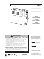
MODELS:
ABSC02787
7.5 KW 240V 1ph generator
_____________________________________
ABSC02789
9
KW
240V
1ph generator
_____________________________________
ABSC02782
12 KW 240V 1ph generator
_____________________________________
! WARNING
REDUCE THE RISK OF OVERHEATING AND SCALDING
1. EXIT IMMEDIATELY IF UNCOMFORTABLE, DIZZY OR SLEEPY.
STAYING TOO LONG IN A HEATED AREA IS CAPABLE OF CAUSING OVERHEATING.
2. CHILDREN UNDER THE AGE OF 16 SHOULD NOT USE THE STEAM BATH.
3. CHECK WITH A DOCTOR BEFORE USE IF PREGNANT, DIABETIC, IN POOR
HEALTH OR UNDER MEDICAL CARE.
4. BREATHING HEATED AIR IN CONJUNCTION WITH CONSUMPTION OF ALCOHOL,
DRUGS, OR MEDICATION IS CAPABLE OF CAUSING UNCONSCIOUSNESS.
5. DO NOT CONTACT STEAM HEAD OR STEAM AT THE STEAM HEAD.
REDUCE THE RISK OF SLIPPING AND FALL INJURY
1. USE CARE WHEN ENTERING OR EXITING THE STEAM ROOM. FLOOR MAY BE SLIPPERY.
NOTE: FOR ADDITIONAL SAFETY CONSIDERATIONS SEE OWNER’S MANUAL
PUR100378HDCA 6.4/08
ANSI
M A DE IN U SA
important note: As you follow
these instructions, you will notice warning
and caution symbols. This blocked information is important for the safe and efficient installation and operation of this generator. These are types of potential hazards
that may occur during this installation and
operation:
!
warning states a hazard may
cause serious injury or death if precautions
are not followed.
!
caution signals a situation
where minor injury or product damage may
occur if you do not follow instructions.
important note:
This highlights information that is especially relevant to a problem-free installation.
__________________________________
All information in these instructions is based
on the latest product information available at
the time of publication. Aquasteam
reserves the right to make changes at any time
without notice.
LIS T E D S T E AM B ATH
GENER ATOR 777D
aquabrass.com
1
Residential Steambath Generator Systems
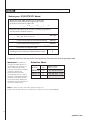
Select your
aquasteam
Model
1. Measure the Length, Width, & Height (in ft.) of steam shower
or tub/shower being used. Multiply the Length x Width x Height
to get the B asic R oom Volume in CUB IC FEET
L _______ x W _______ x H _______ =
a
2. Add to the room volume (a) for each of the following design features
that describe the steambath enclosure:
For natural stones: natural marble,stone
shale, glass block or concrete
Add 100%
For ceramic or porcelain tile on cement board or mortar bed
Add 30%
For each exterior wall or extra glass panel
Add 30%
Add 15% per foot
For each foot exceeding 8ft. in height
3. Add all figures above to obtain the Total Room Volume required
h
Compare the Total Cubic Feet required ( h) to the Specification Chart below and select the appropriate model.
IMPORTANT: The guideline for
selecting the steambath generator is a
recommendation only. B ecause of variables in construction, these sizing
instructions and specifications should be
considered as guidelines only.
Aquasteam will review the model
selected provided we receive complete
information, including working drawings,
specifications, and pertinent electrical
and construction details. Otherwise the
manufacturer disclaims responsibility for
the sizing of a model selected.
Selection Chart
Maximum R oom
Vol. ft3 (cu.meters)
Model No.
KW
ABSC02787
7.5
151-225 (4.27-6.37)
ABSC02789
9
226-360 (6.39-10.19)
ABSC02782
12
476-575 (13.4-16.28)
Note: To convert cubic feet ot cubic meters, divide cubic feet by 35.3.
E xample: Total cubic feet required is 155. Divide by 35.3 to obtain 4.39 m3. S elect model ABSC02787
2
aquabrass.com
Residential Steambath Generator Systems
Before Installing
IMPORTANT: The following general information should be used in conjunction with consultations with your
architect, designer and contractor in determining all factors necessary in providing a suitable and safe steam
room.
R ead these instructions before installation or service. Although this steambath generator has been qualified for
shipment, the following must be reviewed for proper, safe and enjoyable steam bathing.
Verify that the model and accessories are correct, including incoming line voltage.
Insure steambath generator has been correctly sized for the steambath room. Pay particular attention to room
volume and construction. If any questions, please refer to the sizing guide enclosed. (see page 2).
Marble or glass walls or ceilings, or exterior walls “ E NLAR GE ” the room’s size, requiring a generator larger
than one based only on the room’s cubic foot (L x H x W) volume.
The physical size of the unit, clearance for plumbing servicing, and its distance from the steam room must
all be considered before final installation.
Aquasteam units are intended to be operated with aquasteam controls only, and
are to be installed strictly in accordance with the specific instructions contained in this manual.
IMPORTANT:
!
warning ELECTRICAL SHOCK HAZARD.
Aquasteam steam generators are intended for connection to 240V/1ph/60Hz power supply and contain live
electrical components. All lnstallation and service to be performed by qualified and licensed electricians and
plumbers only. Installation or service by unqualified persons may void the warranty.
Steam Room Guidelines
1. S team room must be completely enclosed, with full walls, door, floor and ceiling.
2. It is recommended that a gasketed door is used for heat sealing and steam containment.
3. If tile-type or other smooth surfaced flooring is used provide suitable anti-skid strips or equivalent, to prevent
user slipping and injury.
4. Walls and ceilings must be constructed of water-resistant, non-corrosive surface, such as tile, marble, molded
acrylic, or other non-porous material. The ceiling should be sloped to prevent dripping of condensate. If
acrylic, fiberglass or other non-heat resistant materials are used as part of the steamroom enclosure, see pg.
5, "Steamhead" for additional details.
5. Provide a floor drain.
6. No heating, venting or air conditioning devices should be installed inside the steam room.
7. S team room construction information is available from the Tile Council of America, Inc. by purchasing the
TCA Handbook for Ceramic Tile Installation. Tel: (864) 646-8453 or www.tileusa.com.
8. Windows that are part of the steamroom should be double paned tempered glass.
9. Try to limit steamroom ceiling height to 8 feet. E xceeding 8 feet may require a higher-rated steam generator.
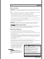
10. It is strongly recommends that a warning
be posted in a conspicuous location near
the steambath. A peel-offwarning has been
REDUCE THE RISK OF OVERHEATING AND SCALDING
provided (on the inside front cover) for
1. EXIT IMMEDIATELY IF UNCOMFORTABLE, DIZZY OR SLEEPY.
installation. S ee Warning facsimile here.
STAYING TOO LONG IN A HEATED AREA IS CAPABLE OF CAUSING OVERHEATING.
! WARNING
! warning Aquasteam steam
generators are for residential use only. Commercial for other non-residential applications void
the warranty and may adversely affect product
preformance.
2. CHILDREN UNDER THE AGE OF 16 SHOULD NOT USE THE STEAM BATH.
3. CHECK WITH A DOCTOR BEFORE USE IF PREGNANT, DIABETIC, IN POOR
HEALTH OR UNDER MEDICAL CARE.
4. BREATHING HEATED AIR IN CONJUNCTION WITH CONSUMPTION OF ALCOHOL,
DRUGS, OR MEDICATION IS CAPABLE OF CAUSING UNCONSCIOUSNESS.
5. DO NOT CONTACT STEAM HEAD OR STEAM AT THE STEAM HEAD.
REDUCE THE RISK OF SLIPPING AND FALL INJURY
1. USE CARE WHEN ENTERING OR EXITING THE STEAM ROOM. FLOOR MAY BE SLIPPERY.
NOTE: FOR ADDITIONAL SAFETY CONSIDERATIONS SEE OWNER’S MANUAL
PUR100378HDCA
6.4/08
aquabrass.com
3
Re s i de n t i a l St e a m ba t h Ge n e r a t or Sy s t e m s
L oc a t i n g t h e St e a m Ge n e r a t or U n i t
Select a location as near as practical and outside the steam room. Typical locations include: closet, vanity
cabinet, heated attic or basement.
1. Locate steambath generator within 25 feet (7.6 m) of steam room.
2. Do not install steambath generator inside steam room.
3. Do not install steambath generator outdoors or wherever environmental conditions may affect the safety
and/or performance of the generator.
4. Do not install steambath generator or plumbing lines in unheated attic or any locations where water
could freeze.
5. Do not install steambath generator near flammable or corrosive materials or chemicals such as gasoline,
paint thinners, or the like. Installation in areas having high concentrations of chlorine (such as pool
equipment room) must be avoided.
6. Install steambath generator on a solid and level surface. Keyhole slots are provided on for wall mounting.
Insure the steam generator is properly secured and level when mounting with keyhole slots.
7. Install steambath generator in an upright position only.
8. Install anti-water hammer device as necessary.
9. Provide a minimum of 12 inches (30cm) at both ends and top of the steam generator or as required for
servicing. See page 6.
10. Provide unions as required to facilitate installation and disconnection of piping.
11. I MPORTA N T : Steam line, safety valve, drain valve, plumbing and steamheads become hot during
operation and remain hot after shutdown for a period of time. Provide appropriate protection, including
insulating plumbing lines. Avoid plumbing runs and steamhead locations that can come in contact with
bathers, wiring and control cables.
12. aquasteam controls can be located inside or outside of the steam room The temperature sensor must
always be placed in the steamroom.
! w a r n i n g Aquasteam steam generators are for residential use only . Commercial or other non-residential
applications void the warranty and may adversely affect product performance. Use only aquasteam
series controls.
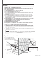
Ty p i c a I a q u a ste a m i nsta l l a ti on
N o t e : For illustrative purposes only.
Consult with qualified designer, architect or
contractor for steam room construction details.
In-Shower
Control
Control Cable
Field installed
power supply
Field
installed
water
supply pipe
Temperature s
IMPORTANT: See pg. 5 & pg.11
for steam head and temperature
sensor location information.
Steam Generator
Valve is
shown open
4
Provideunions asrequired to facilitate
installtion and disconnect of piping
Field
installed
steam
supply pipe
Steam Head
(shown with available acrylic shield)
aquabrass.com
Residential Steambath Generator Systems
Installation
Plumbing
All plumbing shall be performed by a qualified licensed plumber and in accordance with applicable National and
local codes.
Use unions on all pipe connections.
Use only brass piping or copper tubing as permitted by codes.
Do not use black, galvanized or PVC pipe.
Water Supply (3/8” NPT)
1. Connect hot or cold water line. Hot water line is preferable, however hot water should not exceed 160˚F (70° C).
2. Provide a shut offvalve in the water supply line upstream of the steambath generator.
3. Do not overheat inlet solenoid valve with solder connections. Overheating will damage parts.
4. Flush inlet water line thoroughly before making connection to unit.
5. Strainer recommended upstream off eed water connection.
6. For best performance water pressure should be 15-20 psig (1 to 1.3 bar).
R educe pressure as required if necessary.
7. Provide anti-water hammer device as required.
Steam Outlet (1/2” NPT)
1. Do not install any valve in steam line. Flow of steam must be unobstructed.
2. Use 1/2” (15mm) brass pipe or copper tubing from unit to steam head as permitted by codes.
3. Insulate steam line using pipe insulation rated 250˚F (120° C) or higher.
4. Pitch steam line towards steam head or steam generator to avoid valleys and trapping of condensate.
Note: R unning the steam line down and then up will create a steam trap blocking the flow of steam.
Steam Head (1/2” NPT)
!
caution
INSTALLE R : B ecause the steam head and direct steam emissions are very hot, locate the steam
head where incidental contact by bather with the steam head or direct steam emission cannot occur.
1. Locate steam head 6-12 inches (15-30 cm) above floor, except for
Tub/shower enclosures, install 6 in. (15 cm) above tub top edge.
For enclosures with acrylic or other non-heat resistant flooring install Acrylic Shield.
2. Install steamhead with steam discharge slot (opening) facing downward.
Hand tightening is sufficient when teflon or equal pipe thread sealing compound is used.
IMPORTANT: To preserve steam head finish, do not use wrench or other tools to tighten. Use no abrasive
cleansers or chemicals. Use only water with mild soap and a non-abrasive sponge.
3. IMPORTANT: Consult with supplier of acrylic, fiberglass and other non-heat resistant enclosures for recommended steamhead location. Use Acrylic Shield.
Drain (1/2” NPT)
Note: A drain valve is provided to facilitate servicing. Provide a drain line connection from steambath generator
drain valve according to National and local Codes. Check local plumbing code for receptor, trap and vent requirements. Unit drains by gravity.
Safety Valve (3/4” NPT)
Where permitted by local codes, provide an outlet plumbing connection for safety valve.
!
warning To insure proper and automatic safety valve operation: DO NOT connect a shut offvalve or a
plug at safety valve outlet. DO NOT connect a shut offvalve in steam supply pipe.
5
aquabrass.com
Residential Steambath Generator Systems
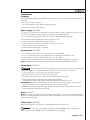
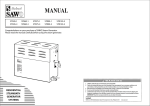
Generator Dimensions
/---------------------------------\
Safety Valve
Optional
Automatic Drain
Manual Drain Valve
/-----------\
A
J
/----- L---\
12”
/----------- G ---------\
/----------------
(305mm)
C
D
/----- F ----\
/------------------------------------------------------------ K-----------------------------------------------------------\
/--------------\
B
/------------------------------------------------------------------------------\
Steam Outlet
/-----------------------------------------------------\
Water Inlet
/--------------------------------------------------------------------------------------------------\
/---- E-----\
M -----------------\
/------------------ H ----------------\
Minimum clearance for element service
/-------------------------------------
I
------------------------------------\
I M P O R T A N T N O T E : P rovide clearance around steam generator as required for service
and maintenance. DO N OT rough in plumbing and electrical services based on dimensional
information provided. Drawing not to scale.
____
ABSC02787
ABSC02789
ABSC02782
____________
INCHE S
MM
INCHE S
MM
___________________________________
A
5-1/8 (130)
7-1/4 (184)
___________________________________
B
8-1/4 (210)
9 7/8 (251)
___________________________________
C
11-7/8 (302)
12-1/2 (310)
___________________________________
D
14-3/4 (375)
18-3/4 (466)
___________________________________
Side View Showing
Element Access Panel
E
1-3/4
(45)
1-3/4 (45)
___________________________________
F
1-7/8
(48)
2-3/8 (60)
___________________________________
G
5-1/8
(130__
4
(102)
________________
_) ________________
H
5
(127)
6
(152)
___________________________________
I
6-3/4 (171)
7-7/8 (200)
___________________________________
J
1-3/4
(45)
1-3/8 (35)
___________________________________
K
14-1/2 (368)
17
(432)
___________________________________
L
2-1/2
(64)
2-3/8 (60)
___________________________________
M
!
caution
6-3/8
(162)
6-3/8
(162)
Notes: M=Optional automatic drain valve system
TO AVOID EQUIPMENT DAMGE DO NOT CONNECT
POWER SUPPLY DIRECTLY TO HEATING ELEMENTS !!!
6
Note: For illustrative purposes only.
aquabrass.com
Residential Steambath Generator Systems
Electrical Specifications
All electrical wiring to be installed by a qualified licensed electrician in accordance with National
E lectrIcal Code and local electrical code.
Power Wiring See “ Field Power Wiring” Diagrams (Page 8)
1. Check power voltage. Use 240V/ 1ph to connect S H aquasteam residential steambath generator.
2. Use minimum 90ºC /600V rated insulated copper conductors only for field wiring, sized in accordance
with National E lectrical Code and local electrical code for the Amps in Ampere Chart.
3. Connect suitably sized equipment grounding wire to ground terminal provided.
4. Install a separate circuit breaker between supply and unit. Provide a power supply disconnect
within sight of the steam generator or one that is capable of being locked in the open position.
______________________________________________________________
Ampere Chart
______________________________________________________________
Maximum Room
Voltage/
Wire Size
3
2
(m
)
KW
phase
Amperes
AWG
(mm2)
Model
No.
Volume
ft
_______________________________________________________________________________________
ABSC02787
225(6.37)
7.5
240/1
32
8 (10)
_______________________________________________________________________
ABSC02789
360 (10.19)
9.0
240/1
38
8 (10)
__________________________________________________________________________
ABSC02782
575 (16.82)
12
240/1
50
6 (16)
_________________________________________________________________________
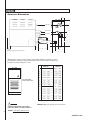
Wiring Diagrams
Diagram
for ABSC02787
ABSC02789
POWER INPUT
L1
L2
L E G E N D (All Diagrams)
G
TRANSFORMER
BLACK
FIELD
WIRING
WHITE
DARK
BLUE
BLACK
FACTORY
WIRING
GREEN
PURPLE
GROUND
WHITE
C
TO PROBE
LIGHT
BLUE
CONTACTOR
S
WATER
FEED
SOLENOID
VAVLE
HEATING
ELEMENT
Diagram
for ABSC02782
WHITE
GRAY
AUTOMATIC DRAIN
(optional)
CONTROL BOARD
POWERINPUT
L1
L E G E N D (All Diagrams)
L2
FIELD
WIRING
TRANSFORMERWHITE
BLACK
FACTORY
WIRING
DARK
BLUE
BLACK
GREEN
!
caution
PURPLE
FUSES
PURPLE
GROUND
TO PROBE
WHITE
TO AVOID EQUIPMENT DAMAGE DO NOT
CONNECT POWER SUPPLY DIRECTLY TO
HEATING ELEMENTS !!!
C
LIGHT
BLUE
CONTACTOR
S
HEATING
ELEMENT
WHITE
GRAY
WATER
FEED
SOLENOID
VALVE
Automatic Drain
(optional)
CONTROL BOARD
7
aquabrass.com
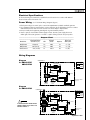
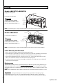
Residential Steambath Generator Systems
Models ABSC02787, ABSC02789
(single phase wiring shown)
Contactor
L
L, N Ground to be field wired
N
!
caution
TO AVOID E QUIPME NT DAMAGE
DO NOT CONNE CT POWE R SUPPLY
DIR E CTLY TO HE ATING E LE ME NTS !!!
Knock-out
(fitting omitted
for clarity)
Ground
Ground Lug
(behind probe)
Note: For illustrative purposes only. Consult with qualified licensed electrician for electrical installation.
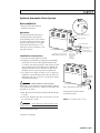
Ground
Models ABSC02782
Power block
Ground lug
Fuse
Fuse block
Contactor
L1, L2, Ground to be field wired
!
caution
TO AVOID E QUIPME NT DAMAGE
DO NOT CONNE CT POWE R SUPPLY
DIR E CTLY TO HE ATING E LE ME NTS !!!
L1
L2
Knock-out
(conduit and fittings
omitted for clarity)
Note: For illustrative purposes only. Consult with qualified licensed electrician for electrical installation.
Initial Start-Up and Checkout
1. Turn on control. Follow specific instruction sheet provided with controls.
2. Steam will begin to appear within 3-5 minutes at the steam head. Steam will shut offwhen desired temperature is reached and will automatically resume when room temperature drops below set point.
3. Steam will shut offautomatically when control timer reaches zero. To shut steam offmanually, turn control
OFF. To clear steam from enclosure area, turn shower on before opening door.
4. If unit does not start and control does not turn ON (control display does not light up) then turn breaker off
for twenty seconds and try again.
Maintenance
aquasteam steambath generators require little maintenance. Other than periodic draining, maintenance procedures are minimal. E very 2 months, or more often in “ hard” water areas, the manual drain valve should be
opened fully flushing out accumulated materials, salts and other particles which are natural by-products of boiling water.
Note: Flush a minimum offi ve hours after the control has been turned offto insure that the water has cooled.
!
warning Draining immediately after a steam cycle may expose PVC and other piping to high
temperaturwater. Check local codes. The unit will refill automatically when the control is activated again.
In areas of hard water, a A q u a s t e a m automatic drain valve system is recommended for generator longevity.
8
aquabrass.com
Residential Steambath Generator Systems
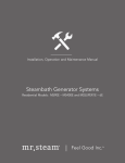
Optional Automatic Drain System
(2) Pin Connector
for Automatic Drain
BOX CONTENTS:
Automatic Drain Valve with Cord
Installation instructions.
Operation
The optional Automatic Drain feature
automatically drains the Aquasteam
system following each use. The stainless
steel tank is flushed and remains empty
until the steam generator is used again.
A time delay allows the water to cool
down before it drains resulting in a safe
and gentle operation.
Automatic Drain Cord Connector
Automatic Drain Cord
Automatic Drain Valve
Arrow indicates correct
direction of flow
Steam Generator
Dra in Va lve
(shown in the connect open position
DO NOT REMOVE THIS DRAIN VALVE
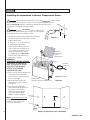
Installation Instructions
1. Disconnect all power supplied to the unit.
2. Plumbing to be performed by a qualified licensed plumber
and shall be in accordance with applicable National and
Local Codes. Unit drains by gravity. A drain line that is lower
than the Automatic Drain assembly must be available. The
Automatic Drain valve outlet is threaded 1/2" NPT. Check
plumbing code for receptor, trap and vent requirements.
3. Use copper or brass nipple 1/2" NPT x 3-1/2" or longer (not
supplied) to connect Automatic Drain valve (end "B ") to the
Drain Valve (valve end “ A” and “ B ” are indicated on bottom
of Automatic Drain Valve)
!
Plumb to Drain Line
in accordance with Code
End
"A"
Automatic
Drain Valve
warning
DO NOT R E MOVE THE DR AIN VALVE .
R emoval may cause equipment and property damage. If there is
not enough room for the valve, an elbow and a short nipple (not
provided) can be added.
4. Open Drain Valve (handle must be aligned with brass nipple
as shown).
5. Connect the automatic drain valve cord connector to the two
pin connector (C) as shown.
!
Nipple
End
Copper or brass
nipple 1/2" NPT "B"
3-1/2" (90mm)
orlonger
(not supplied)
Steam Generator
Drain Valve Nipple
DO NOT TURN OR REMOVE THIS DRAIN VALVE
Plumb to
Drain Line
Automatic drain shown fully assembled.
System drains by gravity.
Note: F or illustrative purposes only.
warning
Do not drain into a steam enclosure or any
location where accidental contact with drain water may occur.
In the event of a power failure the automatic drain valve will
open and discharge hot water.
(continued on next page)
9
aquabrass.com
Residential Steambath Generator Systems
Installing the Aquasteam In-Shower Temperature Probe
!
caution The R emote Temperature Probe is for use with aquasteam in-shower controls.
Controls only. Do not use any other controls. Do not use any other temperature probe
with the aquasteam in-shower controls. Noncompatible products may result in
an inoperative control and a hazardous condition.
!
caution Install the aquasteam control according to the
installation and operation instructions. Failure to do so may result in
an inoperative control and a hazardous condition.
1. Determine the location of the R emote Temperature Probe.
The R emote Temperature Probe must be installed:
A. On a vertical surface
B . 4-5 ft. (1.2 - 1.5 m) above the floor
C. Away from the steam head
D. Not exposed to direct steam emission. The probe has an integral 30 ft.
(9.1 m) cable. Insure that the probe
and/or steam generator are located
accordingly. Contact a aquasteam
technical service representative if a
longer cable is required.
Diagram 1
Printed Circuit
Board Component
shown for
illustrative purpose
Temp Probe
IMPORTANT:
READ BEFORE LOCATING THE PROBE
DO NOT LOCATE THE PROBE NEAR OR
ABOVE THE STEAMHEAD AS THIS MAY
CAUSE DIRECT STEAM EMISSION TO
INTERFERE WITH STEAMROOM
TEMPERATURE REGULATION.
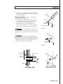
2. Drill a 5/16 inch (8 mm) diameter hole
in the wall as shown in Diagram 1.
Do not oversize or undersize the hole.
Clean area thoroughly.
3. R emove the knock-out from the
steam generator jacket as shown
in Diagram 2.
4. Insert the remote temperature
probe cable through the knock-out
and connect to the connector
onthe steam generator printed
circuit board marked "TE MP
PR OB E " as shown in Diagram 2.
Note: For illustrative purposes only.
Consult with qualified designer,
architect or contractor for steam
room construction details.
Knock-out
Temperature
Sensing Probe
DRAWING NOT TO SCALE
SteamGenerator
(shown with cover removes and NOT installed)
Temperature
Probe
Bad
Diagram 2
Bad
Good
Best
4-5 Feet
(1.2-1.5 m)
Steam Head
ches
6-12 In0 cm)
(15-3
10
Relation of Temperature Probe to Steamhead
aquabrass.com
Residential Steambath Generator Systems
5. R oute the end of the temperature probe cable with the
temperature probe through the wall into the steam room
as shown in Diagram 3.
IMPORTANT NOTE: Do not strain, staple, pinch or
otherwise damage the probe cable.
6. With a minimal length of the cable exposed apply silicone (provided) to the hole in the wall as required to
create a moisture seal as shown in Diagram 3.
7. Push the temperature cable and bulb into hole as
required to leave minimum 1/4 in. (6mm), maximum
1/2 in. (13mm) of the bulb exposed as shown below.
!
warning Insure a minimum of 1/4 in. (6mm) of
S team R oom Interior
Diagram 3
the temperature bulb is exposed to the air. Failure to do so
may result in an inoperative control and a hazardous condition.
!
warning The exposed area of the temperature
bulb must be free of silicone or any materials that prevent
direct exposure to the steam room air. Failure to do so may
interfere with the ability to sense temperature and may
result in excessive steam room temperatures.
Diagram 4
1⁄2" (13 mm)
minimum
Silicone Sealant
3 ⁄4" (90 mm)
maximum
Cable
Wall
SECTIONAL VIEW
INSTALLED REMOTE
TEMPERATURE PROBE
11
aquabrass.com
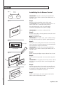
Residential Steambath Generator Systems
Step 1
2 5/8 "
67 mm
Installating the In-Shower Control
1"
1"
25 mm
25 mm
IMPORTANT: Turn power to the steam generator OFF before
installing the control. Failure to turn the power offwill result in an
inoperable control.
Step 1
Determine the desired installation location of the control.
The aquasteam control is designed to be installed inside or outside the steam room as a matter of personal preference.
The control cable length is 30 ft. (9 m) Insure that the
control and/or steam generator are located accordingly.
Step 2
Wall
IMPORTANT: Do not oversize or undersize the hole.
Step 2
R oute the control cable to the steam generator. Connect the connector to the steam generator.
Note: The connector is keyed
IMPORTANT: Do not strain, staple, pinch or otherwise damage
the control cable. R oute cable as required to permit replacement.
Step 4
Adhesive tape
Back of Control
Step 3
Turn on power to the steam generator and test the control to verify
correct connections. Test per the instructions. Proceed with installation and verification of proper control function.
IMPORTANT: Turn power to the steam generator OFF before
installing the control. Failure to turn the power offwill result in an
inoperable control.
Step 4
R emove & discard peel-offpaper to expose adhesive liner as shown.
Step 6
Step 5
R un a bead of silicone (provided) as shown around the edge of the
hole.
IMPORTANT: Do not apply excessive amounts of silicone. Do not
apply silicone to any other parts of the control including the adhesive gasket.
Wall
Keypad
Step 7
Step 6
Insure the mounting surface is clean and dry as required for good
adhesion. Apply silicone into the hole in the wall as required to create a moisture seal. The holder plate may be used to secure the
control if the back of the wall can be accessed.
Wall
Step 7
Hold the control and press the control against the wall until the
adhesive sticks and holds firmly as shown.
12
aquabrass.com
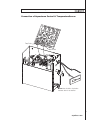
Residential Steambath Generator Systems
Connection of Aquasteam Control & TemperatureSensor
Temp Probe
Main Control
Note: Valve should be closed when
automatic drain is not installed
13
aquabrass.com
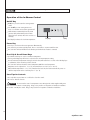
Residential Steambath Generator Systems
Operation of the In-Shower Control
On/Off Key
ON/OFF K ey is used to turn the steam generator
on/off.
Press On/Offkey to turn steam generator on.
Press a second time to turn steam generator off.
A built-in timer automatically shuts the steam
generator offa predetermined period of time
after it has been started, unless the user does so
manually.
The "Display" indicates the S et Point temperature.
Display
Key
Pause Key
Pause key is used to turn the steam generator offmomentarily.
Press Pause key to activate stand-by mode. Press a second time to resume normal function.
The "Set Point" indicator will flash on the function panel when Pause feature is activated.
Scroll Up & Scroll Down Keys
Up & Down arrow keys are used to set ambient temperature.
Pressing and holding keys will increase or decrease the current temperature setting.
The new and desired temperature setting ("S et Point" value) will remain for 5 seconds on the LE D display as
a confirmation of the new value you have selected.
The "Set Point" indicator shows the desired temperature, NOT the actual temperature.
Temperature can be adjusted in 1˚ F (0.5˚ C) increments from 105-120˚F (40.0- 49.0°C).
When ambient temperature is 1˚ F (0.5˚ C) lower than the S et Point, the heater automatically comes on
until the temperature reaches Set Point plus 1˚ F (0.5˚ C).
Care Tips for Controls
1. Use only mild soap and water on a soft cloth to clean the control.
2. Do not use abrasive cleansers
!
caution
Do not route the control or temperature sensor wiring inside conduit together with power
lines or close to hot water or steam piping. Doing so may result in an inoperative or hazardous installation.
Do not alter or modify the control. Doing so may result in an inoperative or hazardous installation.
14
aquabrass.com
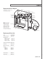
Residential Steambath Generator Systems
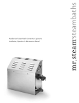
Replacement Parts Diagram
aquasteam shown with access
cover removed for clarity
Contactor
Liquid Level Circuit Board
Water FeedSolenoid
Transformer
Power Supply
Knock-out
Water Feed
Liquid Level
Probe
Plugand Play
Connection
Steam
Outlet
Safety Valve
Note: For illustrative
purposes only. S ome
Access Cover
components may be
omitted or altered for
clarity. Do not use for
wiring, repair or other
HeatingElement
purposes not related
Stainless SteelTank
to component identification.
AutomaticDrain
Valve(optional)
Drain Line
Replacement Parts List
_____________________________________
ITEM
PART NUMBER
_____________________________________
Liquid
Level Probe
ABSP02797
_____________________________________
Heating E lement
ABSC02787 (7.5KW)
ABSP02772
ABSC02789 (9KW)
ABSP02773
ABSC02782 (12KW)
ABSP02774
_____________________________________
Liquid
Level Circuit B oard ABSP02796
_____________________________________
Transformer
ABSP02779
_____________________________________
Water
Feed Solenoid
ABSP02778
_____________________________________
Contactor
ABSC02787
ABSC02789
ABSC02782
ABSP02775
ABSP02775
ABSP02777
_____________________________________
Automatic
Drain
ABDR02771
_____________________________________
Acrylic
S hield
ABSP02776
_____________________________________
15
aquabrass.com
warranty
Residential Steambath
Limited Lifetime Warranty
aquasteam extends to the original consumer purchaser of a
aquasteam. RESIDENTIAL STEAMBATH GENERATOR
(aquasteam Generator), installed in the United States or
Canada (excluding controls and accessories), a warranty that
such aquasteam Generator is free from defects in materials
and workmanship. aquasteam will repair or replace at its
option a Generator if it fails to conform to this warranty.
Limited One Year Warranty for Controls and Accessories
aquasteam extends to the original consumer purchaser of a
Control or Accessory for a aquasteam RESIDENTIAL steambath
generator which is installed in the United
States or Canada, a one year limited warranty that such
aquasteam control and accessory is free from defects in
materials and workmanship. aquasteam still repair or replace
at its option a aquasteam control or accessory if it fails to
conform to this warranty.
Terms, Conditions, and Exclusions
This warranty is non-transferable. All warranties for a
aquasteam Generator and aquasteam control or accessory
(collectively, aquasteamProducts) apply only to the original
consumer purchaser
This warranty does not apply to a aquasteam Product which is
sold “as is” or in a damaged condition or is installed for use in
other than a residential steambathing application.
This warranty does not apply to repairs or replacement
necessitated by any cause beyond the control of aquasteamincluding, but not limited to, any malfunction, defect, or
failure caused by or resulting from unauthorized service or
parts, improper maintenance, and/or problems arising due to
local water conditions, operation contrary to furnished
instructions, damages occurring during shipment, transit,
storage, or handling, or arising from modification or repair by
any person not authorized by aquasteam, abuse, misuse,
neglect, accident, incorrect power line voltage, fire, freezing,
flood, or other Acts of God.
AQUASTEAM PRODUCTS MUST BE INSTALLED, OPERATED,
AND MAINTAINED IN ACCORDANCEWITH aquasteam’S
INSTRUCTIONS. FAILURE TO FOLLOWTHE INSTALLATION,
OPERATION,OR MAINTENANCE PROCEDURES OR USE OF
UNAUTHORIZED PARTS AUTOMATICALLY VOIDS THIS LIMITED
WARRANTY. The original consumer purchaser is responsible
for the suitability of the aquasteam Product for the application intended by such original consumer purchaser. This
limited warranty does not cover any costs incurred for the
16 removal or reinstallation of the aquasteam Product.
THIS WARRANTY DOES NOT APPLY TO AQUASTEAM PRODUCTS WHICH ARE USED FOR ANY NON-RESIDENTIAL OR
COMMERCIAL PURPOSE. THE FOREGOING IS IN LIEU OF ALL
EXPRESS OR IMPLIED WARRANTIES AND AQUASTEAM DOES
NOT ASSUME OR AUTHORIZE ANY PARTY TO ASSUME FOR IT
ANY OTHER OBLIGATION OR LIABILITY. THERE ARE NOWARRANTIES WHICH EXTEND BEYOND THE DESCRIPTION
CONTAINED HEREIN AND SPECIFICALLY LIABILITY FOR ANY
BREACH OF ANY IMPLIED WARRANTY OF MERCHANTABILITY
OR FITNESS FOR A PURPOSE IS EXCLUDED. THE DURATION OF
ANY WARRANTIES WHICH MAY BE IMPLIED BY LAW
OTWITHSTANDING THE PREVIOUS SENTENCE (INCLUDING
THE WARRANTIES OF MERCHANTABILITY AND FITNESS)
SHALL IN NO EVENT EXCEED ONE YEAR. IN NO EVENT SHALL
AQUASTEAM BE LIABLE FOR SPECIAL, INCIDENTAL, OR
CONSEQUENTIAL DAMAGES ARISING FROM OWNERSHIP OR
USE OF ANY AQUASTEAM PRODUCT; OR FOR ANY DELAY IN
THE PERFORMANCE OF ITS OBLIGATIONS UNDER THISWARRANTY DUE TO CAUSES BEYOND ITS CONTROL. SOME STATES
DO NOT ALLOW LIMITATIONS ON HOW LONG ANIMPLIED
WARRANTY LASTS AND/OR DO NOT ALLOW THE EXCLUSION
OR LIMITATION OF CONSEQUENTIAL DAMAGES; SO THE
ABOVE LIMITATIONS AND EXCLUSIONS MAY NOT APPLY TO
YOU. THIS WARRANTY GIVES YOU SPECIFIC LEGAL RIGHTS.
YOU MAY HAVE OTHER RIGHTS, WHICH VARY FROM STATE TO
STATE.
residential steambath generators and control by aquabrass
aquabrass.com