1
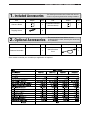
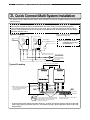
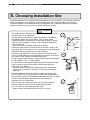
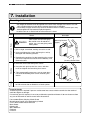
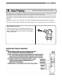
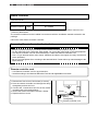
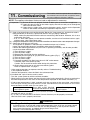
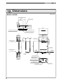
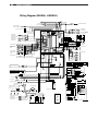
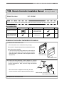
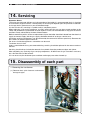
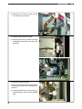
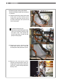
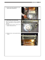
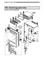
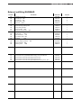
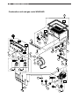
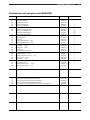
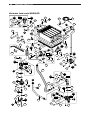
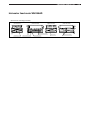
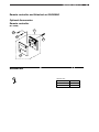
This manual must be kept with the appliance
October 2010
Part No E799
FASTflo
(external)
Installation Guide, Operation and Maintenance Manual
Continuous Flow Wall Hung Balanced Flue
Water Heaters for Natural Gas and LPG
WHX56, LWHX56
Working towards
a cleaner future
2
SECTION XX •
INTRODUCTION
Reproduction of any information in this publication by any method is not permitted
unless prior written approval has been obtained from Andrews Water Heaters.
Andrews Storage Water Heaters have been designed and manufactured to comply
with current international standards of safety. In the interests of the health and safety of
personnel and the continued safe, reliable operation of the equipment, safe working
practices must be employed at all times. The attention of UK users is drawn to their
responsibilities under the Health and Safety Regulations 1993.
All installation and service on Andrews Water Heaters must be carried out by properly
qualified personnel and, therefore, no liability can be accepted for any damage or
malfunction caused as a result of intervention by unauthorised personnel.
Andrews Water Heaters’ policy is one of continuous product improvement and,
therefore, the information in this manual, whilst completely up to date at the time of
publication, may be subject to revision without prior notice.
Further information and assistance can be obtained from:
Andrews Water Heaters
Wood Lane, Erdington,
Birmingham B24 9QP
Tel: 0845 070 1055
Fax: 0845 070 1059
Email: [email protected]
Website: www.andrewswaterheaters.com
Copyright Andrews Water Heaters 2010
CONTENTS
PAGE
GENERAL AND SAFETY INFORMATION
4
SECTION 1
INCLUDED ACCESSORIES
7
SECTION 2
OPTIONAL ACCESSORIES
7
SECTION 3
QUICK CONNECT MULTI SYSTEM INSTALLATION
8
SECTION 4
BEFORE INSTALLATION
9
SECTION 5
CHOOSING INSTALLATION SITE
10
SECTION 6
INSTALLATION CLEARANCES
11
SECTION 7
INSTALLATION
12
SECTION 8
GAS PIPING
13
SECTION 9
WATER PIPING
14
SECTION 10
ELECTRICAL WIRING
15
SECTION 11
COMMISSIONING
17
SECTION 12
DIMENSIONS
WIRING DIAGRAM
19
20
SECTION 13
REMOTE CONTROLLER INSTALLATION
21
SECTION 14
SERVICING
22
SECTION 15
DISASSEMBLY
22
SECTION 16
SERVICING PARTS LIST
32
SPECIFICATIONS
39
3
4
GENERAL SAFETY INFORMATION
GENERAL AND SAFETY INFORMATION
The Andrews Water Heater has been designed for use
with NATURAL GAS OR LPG and is manufactured to give
an efficient, reliable and long service life.
To ensure the continued, trouble-free operation of your
heater at maximum efficiency, it is essential that correct
installation, commissioning, operation and service
procedures are carried out strictly in accordance with the
instructions given in this manual. By law, installation and
commissioning of the heater must be carried out by
properly qualified personnel.
The heater(s) must be installed in accordance with the
following requirements:
The current GAS SAFETY (INSTALLATION AND USE)
REGULATIONS
I/M2
Purging procedures for non-domestic gas
installations.
I/M5
Soundness testing procedures for
industrial and commercial gas
installations.
I/M11
Flues for commercial and industrial gas
fired boilers and air heaters.
I/M16
Notes on installation of gas pipework
(excluding 25mm and below).
LPGA Code of practice 7:
Storage of full and empty LPG cylinders
and cartridges. Highly Flammable Liquids
and Liquid Petroleum Gases Regulations
1972.
The current BUILDING REGULATIONS
The WATER SUPPLY (WATER FITTINGS)
REGULATIONS 1999
Additionally, installation should be performed in
accordance with all relevant requirements of the Gas
Supplier, Local Authority and recommendations of the
British Standards and Codes of Practice detailed below.
BRITISH STANDARDS AND CODES
OF PRACTICE
BS 6700: 1997 Specification for design, installation,
testing and maintenance of services supplying water for
domestic use within buildings and their curtilages. This
standard supersedes the following British Standards and
Codes of Practice: CP99, CP310, CP324, 202, CP342
Part 2, Centralised Hot Water Supply.
BS 5440:1990 Installation of flues and ventilation for gas
appliances of rated output not exceeding
60kW.
Part 1
Specification for installation of flues.
Part 2
Specification for installation of ventilation
for gas appliances.
BS 5546:1990 Installation of gas hot water supplies for
domestic purposes.
BS 6891
Installation of low pressure gas pipework
of up to 28mm in domestic premises.
BS 6644
Installation of gas fired water boilers of
rated inputs between 60kW and 2mW
BS 7206:1990 Specification for unvented hot water
storage units and packages.
IGE/UP/10 Part 1 Edition 2:
Installation of Gas Appliances in Industrial
and Commercial Premises.
Terms:
a. Andrews Water Heaters accepts no liability for any
damage resulting from failing to accurately follow the
instructions.
b. When replacing parts during maintenance, only original
parts from Andrews Water Heaters should be used;
these can be recognised by the name of the
manufacturer printed on them.
HEALTH AND SAFETY REGULATIONS
1993
It is the duty of manufacturers and suppliers of products
for use at work to ensure, so far as is practicable, that
such products are safe and without risk to health when
properly used, and to make available to users adequate
information about their safe and proper operation.
Andrews Water Heaters should only be used in the
manner and purpose for which they are intended and in
accordance with the instructions in this manual. Although
the heaters have been manufactured with paramount
consideration to safety, certain basic safety precautions
highlighted in this manual must be observed by the user.
It is imperative that all users of the heaters must be
provided with all the information and instruction necessary
to ensure correct and safe operation.
GENERAL SAFETY INFORMATION
EFFECTIVENESS IN COMBATING
LEGIONELLA
Water systems in buildings have been associated with
outbreaks of Legionnaires’ Disease, particularly in health
care facilities where occupants are significantly more
susceptible to infection.
In recognition of the risks in hospitals, a Code of Practice
for the Control of Legionella in Health Care premises has
been issued by the Department of Health (1991). Codes of
Practice applicable to other premises have been published
by other organisations, principally the Health and Safety
Executive (HS)(G70) and the Chartered Institute of Building
Services Engineers (CIBSE, TM13).
All Codes of Practice draw attention to the design and
operation of water systems with reference to avoidance of
factors that favour colonisation by Legionella bacteria.
These factors include stagnation, lukewarm conditions
(20°C to 45°C) and the accumulation of debris, scale and
corrosion in the base of tanks and calorifiers.
5
Andrews Water Heaters have commissioned an
independent evaluation of their products to investigate
their resistance to build-up of Legionella bacteria.
Experiments were conducted to determine whether,
following a substantial challenge by legionella
pneumophilia. After overnight and stagnation, the system
was rendered free from viable recoverable legionella. It
was found that at 61°C, following a challenge of
approximately 107 organisms per litre, within one hour,
more than 99.999% of organisms had been killed. After a
subsequent stagnation period, sampling did not reveal any
residual contamination. The design of the base of the
water heater precludes legionella colonisation, even after
build-up of debris. The burner positioning ensures that the
water at the bottom of the heater reaches the same, or
higher, temperatures as in the rest of the heater.
Based on data obtained through experiment, the Andrews
Water Heater can be described as legionella resistant as it
is considered unlikely that, at the temperature tested, the
organism would colonise the water heater and present a
possible health risk.
WARNING: If the information in this manual is not followed exactly, a fire or
explosion may result causing property damage, personal injury or death.
- Do not store or use gasoline or other flammable vapors and liquids in the
vicinity of this or any other appliance.
- WHAT TO DO IF YOU SMELL GAS
• Do not try to light any appliance.
• Do not touch any electrical switch; do not use any phone in your building.
• Immediately call your gas supplier from a neighbor’s phone. Follow the
gas supplier’s instructions.
• If you cannot reach your gas supplier, call the fire department.
- Installation and service must be performed by a qualified installer, service
agency or the gas supplier.
6
GENERAL SAFETY INFORMATION
Installation Manual
GAS WATER HEATER
WHX56, LWHX56
(External)
WARNING: If the information in this manual is not followed exactly, a fire or explosion may result
causing property damage, personal injury or death.
Potential dangers from accidents during installation and use are divided into the following three
categories. Closely observe these warnings, they are critical to your safety.
Danger
Danger of serious injury or even death as well as danger of fire when the
product is misused by ignoring this symbol.
Warning
Possibility of serious injury or even death as well as possibility of fire when
the product is misused by ignoring this symbol.
Caution
Possibility of bodily injury or damage to property when the product is
misused by ignoring this symbol.
Prohibited
Disconnect
Power
Earth
Be sure to do
Requests to Installers
Caution
• In order to use the water heater safely, read this installation manual carefully,
and follow the installation instructions.
• Failures and damage caused by erroneous work or work not as instructed in this manual are not
covered by the warranty.
• Check that the installation was done properly in accordance with this Installation Manual upon
completion.
• After completion of installation, be sure to hand the Operation Manual to the customer upon filling
in all of the required items.
• The appliance must be installed in accordance with the Gas Safety (Installation and Use) Regulations
and the rules in force in the country of installation.
• The manufacturer's instructions supplied.
• The Gas Safety (Installation and Use) Regulations.
• The appropriate Buildings Regulations either The Building Regulations, The Building Regulations
(Scotland), The Building Regulations (Northern lreland).
• In IE, the installation must be carried out by a competent person and installed in accordance with the
current edition of I.S.813 "Domestic Gas Installations", the current Building Regulations and reference
should be made to the current ETCI rules for Electrical Installation.
SAR8285-2
*SAR8285 C*
INCLUDED & OPTIONAL ACCESSORIES
1. Included Accessories
Part
Shape
The following accessories are included with the unit.
Check for any missing items before starting installation.
Q’ty
Part
Owner's Guide
1
Installation Manual
(this document)
Tapping Screw
5
2. Optional Accessories
Part
Remote Controller*
Shape
7
Shape
Q’ty
1
The accessories listed below are not
included with the units, but may be necessary
for installation.
Q’ty
Part
1
Quick Connect
Cord
*One remote controller per controller per application is required
Shape
Q’ty
1
8
QUICK CONNECT MULTI SYSTEM INSTALLATION
3. Quick Connect Multi System Installation
• The Quick Connect Multi System allows the installation of two units together utilizing only the Quick
Connect Cord.
The Quick Connect Cord is 2m. long. Install the two units 470mm-950mm apart at the center to
ensure the cord will be able to reach between the units. (See Typical Plumbing diagram).
(If the distance between the two units is too great, not only will the cord not be able to reach,
but the water temperature may also become unstable because of the difference in pipe length
between the two units.)
* When connecting 2 devices, use only a
single remote controller.
System Diagram
Quick Connect
Cord
Cord
Connector
Cord
Connector
Note: Connect the remote
controller to only one
of the devices.
Terminal Block
Remote Controller
Remote Controller Cord
Gas Supply Piping
G
Cold Water Supply
Hot Water
Typical Plumbing
Distance at center: 470 - 950mm.
Distance on sides
5 - 480mm.
Union
Union
Make this distance as short as possible.
* The hot water temperature will
become unstable as the pipe
length increases.
Quick Connect
Cord
Shutoff
Valve
Union
Gas Valve
Shutoff Valve
Shutoff
Valve
Hot Water
Cold Water
Leave enough clearance around the plumbing
to apply insulation. It will be necessary to add
bends to the piping to ensure that this
clearance is available.
Size the piping to allow for the maximum
flow rates of the units.
• Insulate the hot water piping to prevent heat loss. Insulate and apply heating materials to the cold
water supply piping to prevent heat loss and freezing of pipes when exposed to excessively cold
temperatures.
BEFORE INSTALLATION
4. Before Installation
Caution
Check the Gas
• Check that the rating plate indicates the correct type of gas.
Check that the gas supply line is sized
for 62.3 kW(or 49.0 kW) for this unit.
Check the Power
• The power supply required is 230V AC,
at 50Hz. Using the incorrect voltage
may result in fire or electric shock.
Do Not Use Equipment for Purposes Other Than Those Specified
• Do not use for purposes other than increasing the temperature of the water supply,
as unexpected accidents may occur as a result.
Check Water Supply Quality
• If the water supply is hard, acidic or otherwise impure, treat the water with approved methods in
order to ensure full warranty coverage.
Use Extreme Caution if Using With A Solar Pre-Heater
• Using this unit with a solar pre-heater can lead to unpredictable output temperatures and
possibly scalding. If absolutely necessary, use mixing valves to ensure output temperatures do
not get to scalding levels. Do not use a solar pre-heater with the quick-connect multi-system.
Checkup
• Check the fixing brackets yearly for damage or wear. Replace if necessary.
4
9
10
CHOOSING AN INSTALLATION SITE
5. Choosing Installation Site
* Locate the appliance in an area where leakage from the unit or connections will not result in damage
to the area adjacent to the appliance or to the lower floors of the structure. When such locations
cannot be avoided, it is recommended that a suitable drain pan, adequately drained, be installed
under the appliance. The pan must not restrict combustion air flow.
Caution
• The water heater is designed for external installation only. Never
install it indoors or in a bathroom.
• Consult with the customer concerning the location of installation.
• Avoid places where fires are common, such as those where
gasoline, benzene and adhesives are handled, or places in which
corrosive gases (ammonia, chlorine, sulfur, ethylene compounds,
acids) are present.
This may cause incomplete combustion or failures.
• Locate the water heater so that there are no obstacles around the
termination and so that exhaust can't accumulate. Do not enclose the
termination with corrugated metal or other materials.
• Install the water heater in an area that allows for the proper clearances to combustible and noncombustible construction. Consult the
rating plate on the appliance for proper clearances.
• Do not install the water heater in a place where it may be threatened
by falling objects, such as under shelves.
• Do not install the water heater where the exhaust will blow on outer
walls or material not resistant to heat. Also consider the surrounding trees and animals.
The heat and moisture from the water heater may cause discoloration of walls and resinous materials, or corrosion of aluminum
materials.
• Avoid installation in places where dust or debris will accumulate.
Dust may block the air-supply opening, causing the performance of
the fan motor to drop and incomplete combustion to occur as a result.
• Install in a location where the exhaust gas flow will not be
affected by fans or range hoods.
• Take care that noise and exhaust gas will not affect neighbors.
• Avoid installation in places where special chemical agents
(e.g., hair spray or spray detergent) are used.
Ignition failures and malfunction may occur as a result.
Internal
installation
INSTALLATION CLEARANCES
6. Installation Clearances
11
Caution
Before installing, check for the following:
Install in accordance with relevant building and mechanical codes, as well as any local, state or
national regulations.
Check
Illustration
• Maintain the following clearances
from both combustible and
non-combustible materials.
Combustibles
Combustibles
600 mm
or more
10 mm
or more
Combustibles
300 mm
or more
Combustibles
Distance from combustibles
Item
150 mm
or more
Combustibles
150 mm or more
Clearances to Opening
into Any Building
• There must be a clearance of 600mm or
more in front of the exhaust terminal.
• This restriction will not be applied to an
area where an effective shield makes a
clearance of 600mm or more in front of
the exhaust outlet.
There must be no
building opening
within this area.
300 mm
or more
150 mm
or more
150 mm
or more
150 mm
or more
12
INSTALLATION
7. Installation
Securing to the wall
• The weight of the device will be applied to the wall. If the strength of the wall is not sufficient, reinforcement must be done to prevent the transfer of vibration.
• Do not drop or apply unnecessary force to the device when installing. Internal parts may
be damaged and may become highly dangerous.
• Install the unit on a vertical wall and ensure that it is level.
Item
Check
Locating Screw Holes
Caution
• When installing with bare hands,
take caution to not inflict injury.
• Be careful not to hit electrical
wiring, gas, or water piping while
drilling holes.
Mounting
Location of Screw Hole
Mounting Bracket
(upper)
1. Drill a single screw hole, making sure to hit a stud.
2. Insert and tighten the screw and hang the unit by
the upper wall mounting bracket.
3. Determine the positions for the remaining four screws
(two for the top bracket and two for the bottom), and
remove the unit.
4. Drill holes for the remaining four screws.
Structure
Illustration
Locating Screw Holes
Tapping Screw
5. Hang the unit again by the first screw, and then
insert and tighten the remaining four screws.
6. Take waterproofing measures so that water does
not enter the building from screws mounting the
device.
• Make sure the unit is installed securely so that it will
not fall or move due to vibrations or earth-quakes.
Terminal Guards
A terminal guard is required if persons could come into contact with the terminal or the terminal
could be subject to damage.
If a terminal guard is required, it must be positioned to provide minimum of 50 mm clearance from
any part of the terminal and be central over the terminal.
Part number:E528, Stainless Mesh Guard
Manufacturer Details: KDS Engineering Limited
Unit 7, Moor Street Industrial Estate
Moor Street
Brierley Hill
West Midlands
England
DY5 3ST
GAS PIPING
8. Gas Piping
13
Follow the instructions from the gas supplier.
The appliance and its individual shutoff valve must be disconnected from the gas supply piping system
during any pressure testing of that system at test pressures in excess of 35 mbar.
The Appliance must be isolated from the gas supply piping system by closing its individual manual shutoff
valve during any pressure testing of the gas supply piping system at test pressures equal to or less than
35 mbar.
The appliance and its gas connections must be leak tested before placing the appliance in operation.
The inlet gas pressure must be within the range specified. This is for the purposes of input adjustment.
Measuring Gas Pressure
In order to check the gas supply pressure to the unit, a
tap is provided on the gas inlet. Remove the hex head
philips screw from the tap, and connect a manometer
using a silicon tube.
14
WATER PIPING
9. Water Piping
Ask a qualified plumber to perform the installation
of the plumbing. Observe all applicable codes.
This appliance is suitable for potable water. Do not use this appliance if any part has been underwater. Immediately
call a qualified service technician to inspect the appliance and replace any part of the control system and gas control
which has been under water.
If the water heater is installed in a closed water supply system, such as one having a backflow preventer in the cold
water supply line, means shall be provided to control thermal expansion. Contact ANDREWS WATER HEATERS
TECHNICAL DEPARTMENT FOR ADVICE.
Piping and components connected to the water heater shall be suitable for use with potable water.
Toxic chemicals, such as those used for boiler treatment, shall not be introduced into the potable water.
A water heater used to supply potable water may not be connected to any heating system or components previously
used with a nonpotable water heating appliance.
When water is required in one part of the system at a higher temperature than in the rest of the system, means such
as a mixing valve shall be installed to temper the water to reduce the scalding hazard.
• Flush water through the pipe to clean out metal powder, sand and dirt before connecting it.
• Take appropriate heat insulation measures (e.g., wrapping with heat insulation materials, using electric heaters)
according to the climate of the region to prevent the pipe from freezing.
• Use a union coupling or flexible pipe for connecting the pipes to reduce the force applied to the piping.
• Do not use piping with a diameter smaller than the coupling.
• When feed water pressure is too high, insert a depressurizing valve, or take water hammer prevention measures.
• Avoid using joints as much as possible to keep the piping simple.
• Avoid piping in which an air holdup can occur.
• Use approved piping materials.
• If installing the unit on a roof:
If the unit is installed on a roof to supply water to the levels below, make sure that the water pressure supplied to
the unit does not drop below 2000 mbar. It may be necessary to install a pump system to ensure that the water
pressure is maintained at this level.
Check the pressure before putting the unit into operation.
Failing to supply the proper pressure to the unit may result in noisy operation, shorter lifetime of the unit, and
may cause the unit to shut down frequently.
Supply water piping
• Do not use PVC piping.
• Mount a check valve and a shut off valve (near
the inlet).
• In order for the client to use the water heater
comfortably, 1000 mbar to 5000 mbar of pressure is needed from the water supply.
Be sure to check the water pressure. If the water
pressure is low, the water heater cannot perform
to its full capability, and may become a source of
trouble for the client.
Hot water piping
• Do not use lead or PVC piping.
• The longer the piping, the greater the heat loss.
Try to make the piping as short as possible.
• Use a mixing valve with a low water resistance.
Use shower heads with low pressure loss.
• If necessary, use a pump or other means to ensure that the supply water pressure to the inlet
of the heater does not fall below 2000 mbar when
the maximum amount of water is being demanded. Also install a pressure meter on the inlet. If this is not done, local boiling will occur inDrain piping
side the water heater causing abnormal sounds
• Expansion water may drop from the pressure
and decreasing the durability of the heat exprevention device and wet the floor. If neceschanger.
sary, provide drain piping or use a drain hose to
remove the water.
ELECTRICAL WIRING
10. Electrical Wiring
15
Consult a qualified electrician
for the electrical work.
Do not connect electrical power to the unit until all electrical wiring has been completed.
i) "A means of disconnection from the supply mains having a contact separation in all poles must be provided to allow for full disconnection".
ii) Under voltage Cat III conditions should be incorporated in the fixed wiring in accordance with the wiring
regulations.
iii) "If the supply cord is damaged, it must be replaced by the manufacturer or its service agent".
This appliance must be electrically grounded in accordance with Electrical Authority Regulations.
External wiring must be correctly earthed, polarised and in accordance with the relevant standards.
In GB this is BS 6891.
In IE this is the current edition of I.S.813 "Domestic Gas Installations".
The boiler must be connected to a permanent 230 V ac, 50Hz supply.
Connection of the whole electrical system of the boiler, including any heating controls, to the electrical supply
must be through one common isolator and must be fused 10 Amp maximum.
Isolation should be by a double pole switched fused spur box, with a minimum gap of 3 mm for both poles.
The fused spur box should be readily accessible and preferably adjacent to the appliance. It should be
identified as to its use.
Caution: Label all wires prior to disconnection when servicing controls. Wiring errors can cause improper
and dangerous operation.
Verify proper operation after servicing.
Field wiring to be performed at time of appliance installation.
Caution
Do not turn on the power until the electrical wiring is finished.
This may cause electrical shock or damage to the equipment to occur.
• The electrical supply required by the water
heater is 230V AC at 50 Hz.
The power consumption may be up to 135W.
Use an appropriate circuit.
• Do not disconnect the power supply when not
in use. When the power is off, the freeze
prevention in the water heater will not activate, resulting in possible freezing damage.
Ground
• To prevent an electric shock, always plug power
lead into an earth powerpoint.
• Do not let the power cord contact the gas piping.
Tie the redundant power cord outside the
water heater. Putting the redundant length of
cord inside the water heater may cause electrical interference and faulty operation.
THE APPLIANCE MUST BE EARTHED
16
ELECTRICAL WIRING
Remote Controller
• Applicable Model
WHX56, LWHX56
Remote controller
Main
RC-7508M
* Up to three remote controllers can be connected. Additional remote controllers cannot be connected by themselves.
• The remote controller must be installed in accordance with the installation manual enclosed in the
package.
•
Cannot be used without a remote controller.
Connecting Remote Controller Cord to Unit
•
•
•
•
Keep the remote controller cord away from the freeze prevention heaters in the unit.
Tie the redundant cord outside the water heater. Do not put the extra length inside the equipment.
The remote controller cord can be extended up to 100m with Remote controller cord.
Use a Y type terminal with a resin sleeve. (Without the sleeve, the copper wire may corrode and
cause problems).
• Be sure to hand tighten when screwing to the terminal block. Power tools may cause damage to the
terminal block.
Remote controller cord
• Use Remote controller cord for any extensions.
• Install according to the National Electrical Code and all applicable local codes.
1. Remove the front cover of the heater (4 screws).
2. Pass the remote controller cord through the wiring
throughway and into the unit.
3. Connect the Y terminals at the end of the remote
controller cord to the terminal block.
4. Secure the remote controller cord with a clamp.
5. Replace the front cover.
Clamp
Wiring
Throughway
Terminal Block
Remote controller cord
COMMISSIONING
11. Commissioning
17
The installer should test operate the unit, explain to
the customer how to use the unit, and give the owner
this manual before leaving the installation
NOTE: The appliance has been factory set and no adjustment is necessary.
• Preparation ... (1) Ensure all lines are purged / flushed of debris prior to connection to appliance.
(2) Open the shut off valve on the water supply, check that water passes through the
valve and close the valve.
(3) Open the gas supply valve, turn on the power supply, and turn on the Operation
switch on the remote controller (the Operation lamp turns on) .
(1) Open a hot water fixture and confirm that the "Burner On" lamp comes on, and that hot water is
being produced. (If necessary, repeat until the air in the gas piping is bled out).
* White smoke may be noticed from the exhaust vent during cold weather. However, this is not a
malfunction of the unit.
* If an “11” error code appears on the remote controller, turn the unit off and then back on again,
and then open a hot water fixture again.
(2) Change the temperature setting on the remote controller and check that the water temperature changes.
(3) Check the secondary gas pressure.
The regulator on products is electronically controlled and pre-set in factory.
It does not require adjustment on installation under normal condition.
Perform the following procedure only if the unit is operating incorrectly and all other possible
causes have been eliminated.
1) Turn off the gas supply.
2) Turn off power supply.
3) Remove the front panel from the appliance.
4) Attached pressure gauge to gas pressure checking point. (Fig.1)
5) Turn on the gas supply
6) Turn on power supply
7) If remote controllers are fitted, turn the unit “ON” at the remote
controller; open a hot water tap fully.
Caution: Do not touch hot water outlet during this procedure.
8) Check the gas pressure at gas pressure checking point.
Refer to “Specification” on page 2.
• If the water heater does not operate normally, refer to “Troubleshooting”
in the Operation Manual.
* After the trial operation, clean the filter in the cold water inlet.
(Fig.1)
<If installed with a quick connect multi-system>
• Turn the system power on with the remote controller.
• Slowly open a hot water fixture and check that the units ignite sequentially. Check to see that the
hot water temperature is the same as the temperature displayed on the remote controller. (*1)
* If inlet water temperature is high, and both units do not ignite at the same time, switch which
unit will ignite first by pressing the Max. or Min. Manifold Pressure Set Button on the circuit
board and then confirm each unit can ignite. (*2)
Press Max. or Min. Manifold
Unit A Doesn't Ignite
Unit A Ignites
Pressure Set Button on Unit B
Unit B Ignites
Unit B Doesn't Ignite
* If an 11 or F11 error code flashes on the remote controller, hit the Power Button on the remote
controller off and on 2-3 times.
* If (*1) and (*2) cannot be done, the Quick Connect Cord may not be properly connected.
Check that the cord is properly connected.
Caution
Handling after trial operation
• In Freezing areas: If the unit will not be used immediately, close off all gas and water shutoff
valves, drain all of the water out of the unit and the plumbing system to prevent the unit
and system from freezing, and bleed the gas out of the gas line.
Freezing is not covered by the warranty.
18
COMMISSIONING
Lighting Instructions
This water heater does not have a pilot. It is equipped with an ignition device that automatically lights
the burner.
1. Read the safety information in the installation manual or on the front of the water heater.
2. Turn off all electrical power to the unit.
3. Do not attempt to light the burner by hand.
4. Turn the gas control manual valve (external to the unit) clockwise to the off position.
5. Wait five minutes to clear out any gas. If the smell of gas remains, stop, and follow the instructions
on page 4 of this manual.
6. Turn the gas control manual valve counterclockwise to the on position.
7. Turn on electric power to the unit.
8. The unit will now operate whenever hot water is called for. If the unit will not operate, follow the
shutdown instructions and call a service technician.
Shutdown Instructions
1. Stop any water demand.
2. Turn off electric power.
3. Turn the gas control manual valve clockwise to the off position.
Should overheating occur, or the gas supply fail to shut off, turn off the gas control manual valve to the
appliance.
DIMENSIONS
19
12. Dimensions
(unit: mm)
WHX56, LWHX56
(VIEW FROM TOP)
361
GAS INLET (3/4)
244
60
169
87
140
70
50
450
HOT WATER OUTLET (3/4)
COLD WATER INLET (3/4)
WIRING THROUGHWAYS
170
464
140
100
70
36
10
240
450
6
257
60
23
39.7
FLUE COLLAR
665.2
615
45
UPPER WALL MOUNT
BRACKETS
LOWER WALL MOUNT
BRACKETS
AIR INLET
100
140
170
10
51
55
36
70
BOTTOM
OF CASE
44
BOTTOM
OF CASE
COLD WATER INLET
WATER DRAIN VALVE
(WATER FILTER)
COLL
GROUND
WIRING THROUGHWAYS
GAS
HOT
HOT WATER OUTLET
WATER DRAIN VALVES
WATER DRAIN VALVE
4
GAS INLET
20
WIRING DIAGRAM
Wiring Diagram (WHX56, LWHX56 )
BR
BR
W 1
2
3
(UN-USED)
(VACANT CONNECTOR)
AIRFLOW CHANGE
-OVER CONNECTOR
R
W
1
2
3
4
5
6
7
(VACANT CONNECTOR)
BL
<CN102>
<CN89>
1 2 3 4 5 6
BL
BL
15
14
13
12
11
10
9
8
7
6
5
4
3
2
1
<CN63>
1 2 3 4 5 6 7 8 9
MAIN CIRCUIT
BOARD
<CN38>
INLET WATER
THERMISTOR
W 3 W
2
W 1 W
HEAT EXCHANGER
THERMISTOR
W
W 4 W
3
2
W 1 W
W
W 2 W
W 1 W
OPERATING LED
2
1
BK
W
SM
(VCC)
LS
(VCC)
(Fully open)
(GND)
SM
(VCC)
LS
(VCC)
(Fully open)
(GND)
2 1
4 3
6 5
8 7
10 9
12 11
14 13
16 15
18 17
20 19
22 21
24 23
26 25
28 27
30 29
32 31
Y
R
BL
BL
BK
V
W
G
O
R
Y
BL
8
7
6
5
4
3
2
1
BK
V
W
G
O
R
Y
BL
BK
V
W
G
O
R
Y
BL
8
7
6
5
4
3
2
1
BK
V
W
G
O
1
BL
1
Y
R
BL
3
2
1
Y
R
BL
(Pulse)
(VCC)
(GND)
QS
MAIN WATER
FLOW SENSOR
(Pulse)
(VCC)
(GND)
QS
BYPASS WATER FLOW
SENSOR
MAIN CIRCUIT
BOARD
Manifold Gas Pressure
Increase Button
Manifold Gas Pressure
Decrease Button
Minimum Manifold Pressure Set Button
Maximum Manifold Pressure Set Button
R
R
R
BL
BL
G
W
BK
R
6
5
4
3
2
1
184
BL
BL
G
W
BK
R
6
5
4
3
2
1
<CN184>
(For Quick Connect Multi System Only)
6
5
4
3
2
1
BL
BL
BL
G
W
BK
R
BL
BL
G
W
BK
R
6
5
4
3
2
1
6
5
4
3
2
1
Quick Connect Cord(Optional)
BL
BL
(G)BK
(W)R
(BK)G
(R)W
BL
BL
G(BK)
W(R)
BK(G)
R(W)
6
5
4
3
2
1
<CN184>
1 2 3 4
5 6 7 8
<CN78>
1 3 5
2 4 6
BL
R
O
BL
BR
GY
W
BK
<CN10>
BL
8 BL
7 R
6 O
5 BL
4 BR
3 GY
2 W
1 BK
DU
10
W
BK
OY
<CN160>
<CN102> BL R
3 2 1
BK R
R
G
GAS VALVE UNIT
R
W
SV
0
<CN1>
R
Y
BL
BL
4 3 2 1
BL
3
2
1
Other Unit in Quick Connect Multi System
BK
W
THERMAL FUSE
BURNER THERMISTOR
R
<CN75>
1
BYPASS WATER
FLOW CONTROL
VALVE
Y
R
BL
R
R
3
2
1
MAIN WATER
FLOW CONTROL
VALVE
R
W
2 2 O
1 1 O
O
OUTLET WATER
THERMISTOR
1
2
3
R
BL
2 R
1 BL
5 4 3 2 1
9
<CN
89A>
11
SV
Q1
12
SV
Q2
13
SV
Q3
14
SV
Q4
BK
W
7 6 5 4 3 2 1
GAS MANIFOLD
<CN27>
7
6
5
4
3
2
1
<CN104>
G
BL
GY
GY
O
O
BK
W
BR
2 1
BR
<CN101>
LIVE
NEUTRAL
VARISTOR
<CN92>
REMOTE CONTROLLER
CURRENT LEAKAGE SAFETY DEVICE
1
2
3
POWER CIRCUIT
BOARD
FREEZE PROTECTION
THERMOSTAT
2
1
BL
BL
RELAY 9
EARTH
1
SYSTEM CONTROLLER
RELAY 3
R
BK
B5 2
10A(FUSE)
AC100V
RC TERMINAL
RELAY 1
IG
SV0
SV1
IGNITER
SOLENOID VALVE 0
HIGH LIMIT
SWITCH
SOLENOID VALVE Q1
RELAY 10
(OPTIONAL)
RELAY 4
DC90V
RELAY 5
RELAY 2
DC140V
FLAME ROD
W (Vs)
W
BL(GND)
R (Vcc)
Y (FG)
O (Vsp)
BL
R
Y
O
W
6
5
4
3
2
1
W
BL
R
Y
O
BL
R
Y
O
IGNITER
IG
ELECTRODE
6
5
4
3
2
1
SV2
SV3
SV4
SOLENOID VALVE Q2
DC90V
SOLENOID VALVE Q3
SOLENOID VALVE Q4
DC140V
W
POWER
CONTROLLER
BL
R
Y
O
FAN FAN MOTOR
A
B
DC15V(2)
PRIMARY
W
BK
FAN CONTROL
OUTPUT
SECONDARY
DC15V(1)
HIGH-LIMIT SWITCH
W
W
BK
W
2
1
BK BK W
1
2
BR
BR
1 1
2 2
GY
BR
(VACANT CONNECTOR)
BR
MAIN WATER FLOW SENSOR
BYPASS WATER FLOW SENSOR
Sub-CPU
SUB
CONTROL
UNIT
MAIN WATER FLOW CONTROL VALVE
TRANSFORMER
BYPASS WATER FLOW CONTROL VALVE
CPU
(VACANT CONNECTOR)
THERMAL FUSE
CENTRAL
PROCESSING
UNIT
RELAY 1
BR
BL
BR
BL
Y/G
Y/G
Y/G
EARTH
EARTH
EARTH
FREEZE PROTECTION
THERMOSTAT
FREEZE PROTECTION
THERMOSTAT
1
2
W
BL
BL
W
BL
BR
GY
BL
BR
1
2
3
BR
GY
BL
BL
W
3
2
1
RELAY 5
WW
WW
D
OUTLET WATER THERMISTOR
HEAT EXCHANGER
THERMISTOR
BL
W
BL
BL/W W
C
INLET WATER THERMISTOR
RELAY 2
<AC230V>
A
B
15V POWER CIRCUIT
GND
URRENT LEAKAGE
AFETY DEVICE
GFCI)
FAN
PULSE
CONTROL
CIRCUIT
FAN ROTATION
SPEED INPUT
2 1
(UN-USED)
EARTH
PRIMARY
SECONDARY
FAN MOTOR FM
VARISTOR ARRESTER
FREEZE PREVENTION
HEATER
AC230V
BL
BL
WW
WW
1 2
2 1
2 1
2 1
2 1
WW
WW
WW
WW
WW
BL
FREEZE PREVENTION HEATER
COLOR CODING
W : White
R : Red
BK : Black
V : Violet
O : Orange
BL : Blue
GY : Gray
G : Green
BR : Brown
Y : Yellow
RELAY
DRIVING
CIRCUIT
RELAY 7
FREEZE PROTECTION
THERMISTOR
BURNER THERMISTOR
RELAY 9
RELAY 10
DU
D
GAS PROPORTION VALVE
POWER CONTROL CIRCUIT
FLAME DETECTING CIRCUIT
FR FLAME ROD
EARTH
C
5V POWER CIRCUIT
GND
REMOE CONTROLLER INSTALLATION
13. Remote Controller Installation Manual
Model Number:
21
For Installers:
Read this installation guide carefully
before carrying out installation.
RC-7508M
Note
Do not connect power to the water heater before the remote controller has been properly installed.
Accessories
Part
Shape
Q’ty
Part
Shape
Remote Controller*
1
Cross recessed
flat-head screw
2
Cross recessed flathead wood screw
2
Wall anchor
2
Q’ty
*Must be purchased, one per application
Remote Controller Installation Procedure
(1) Remove the decorative cover.
(The decorative cover is attached very simply.)
Connect the Y-shaped terminal to the terminal block at the
back of the remote controller.
* In the case of exposed wiring (attachment to the wall), first
open up the cord intake on the main remote controller
body using pliers. (Take care not to damage the board in
the process.)
T
SE
ON
FF
/O
Main remote
controller body
Decorative cover
(2) Position the holes (diameter: 6 mm X depth: 25 - 30 mm)
to secure the remote controller for the kitchen, and knock
in all the wall anchors. Next, secure it using oval-headed
wood screws.
T
SE
* The screws must be tightened manually, and the
remote controller secured properly without rattling.
Main remote controller body
Oval-headed wood screws
(3) Replace the decorative cover.
22
SERVICING & DISASSEMBLY
14. Servicing
Important Notes
To ensure the continued efficient and safe operation of the boiler it is recommended that it is checked
and serviced at regular intervals. The frequency of servicing will depend upon the particular installation
and usage, but in general once a year should be enough.
It is the Law that any servicing is carried out by a competent person.
When replacing a part on this appliance, use only spare parts that you can be assured conform to the
safety and performance specification that we require. Do not use reconditioned or copy parts that have
not been clearly authorised by Andrews Water Heaters.
Before commencing with a service or replacement of parts the boiler should be isolated from the electrical
supply and water supply and the gas supply should be turned off at the gas service cock.
All routine servicing requirements can be achieved by the removal of the front panel only. Remove the
four screws on the front panel and lift off.
For access inside the appliances screwdriver can be used.
To remove chassis front.
Unless stated otherwise any part removed during servicing should be replaced in the reverse order to
removal.
Servicing should always include the removal of any debris from the condensate pipe and siphon.
After completing any servicing of gas carrying components, ALWAYS test for gas soundness and carry
out a functional test of the controls.
It is not necessary for the burner parts and heat exchanger parts to be cleaned up.
15. Disassembly of each part
1. Removing the transformer
(1) Remove the 2 quick fasteners and remove
the bypass pipe.
1
DISASSEMBLY
(2) Remove the 2 locking screws of the
transformer, then pull out.
2. Removing the electric board
(1) Remove the locking screws at the top
and bottom and ground screw, then pull
board out.
3. Removing the manifold
• Remove the electric board and fixing plate
of the ground-fault circuit interrupter in
advance.
(1) Remove the locking screw of the gas
electromagnetic valve and the manifold
pipe.
8
23
24
DISASSEMBLY
4 manifold locking screws.
(3) Pull up and remove the manifold.
4. Removing the hot-water supply fan
• Remove the electric board, manifold and
intake gas pipe in advance.
(1) Remove the 3 fan locking screws, then
pull out.
DISASSEMBLY
(2) Pull out the fan motor.
5. Removing the gas electromagnetic
valve block
• Remove the electric board and manifold
in advance.
(1) Remove the gas electromagnetic valve
locking screw.
(2) Pull up the gas electromagnetic valve
to the upper section and remove it.
25
26
DISASSEMBLY
6. Removing the mixing tube block
• Remove the electric board and connectors
in advance.
(1) Remove the locking screw of the intake
water pipe and the locking quick
fastener of water flow sensor set 3 of
the heat exchanger, then pull out the
intake water pipe.
For Quick-discharge type
Remove the intake water pipe locking
screw and 2 locking fasteners of the
non-return valve, then remove the
intake water pipe and pull out the
pump discharge pipe.
(2) Remove the quick fastener of the
water flow sensor set 1 and the
discharge hot-water pipe locking screw.
(3) R e m o v e t h e c o n n e c t i n g q u i c k
fasteners of the water flow sensor set
3 adjustment valve and the water flow
servo set 2, and the mixing body block
locking screw.
DISASSEMBLY
(4) Pull up the mixing tube block to the
upper section and remove it.
7. Removing the heat exchanger
• Remove the electric board, manifold,
mixing tube block and connectors in
advance.
(1) Remove the 3 locking screws at the
bottom of the burner case.
(2) Remove the 2 case top plate locking
screws.
27
28
SERVICING PARTS LIST
16. Servicing parts lists
External outfitting LWHX56AD
070
010
072
011
008
007
009
012
025
001
073
003
070
050
071
002
023
040
039
003
027
022
070
070
005
004
021
730
SERVICING PARTS LIST
External outfitting WHX56AD
Part Nos.
Part Names
Order Nos.
Q'ty/unit
001
WHX56AD Front set-AS
SKA7262
1
002
003
Front packing S
Front packing L
AA P
AAP
AAPL015
AAPL017
1
2
004
005
Lamp seal plate DEC
Piping label
EDM
DECK008
EDMK004
1
1
007
008
Exhaust top W
EL E
Exhaust box flange packing CRP
ELEF005
CRPL007
1
1
009
Front top packing Q CZR
CZRL001
1
010
011
012
Exhause box SET DHN
Exhaust box silencer board CRP
Exhaust joint packing DHN
DHNF001
CRPF012
DHNL003
1
1
1
021
Acoustic foam 1
DHNL006
1
022
023
Caution label W AD
ELE
Plug insulation sheet CRU
ELEK062
CRUK002
1
1
025
027
Case W AD
Cord bushing C1
ELEA006
7355009
1
1
039
Connection diagram label AD
ELEK063
1
040
050
Raintight seal plate
Connecting cord 2
BUBK004
DMBJ010
1
1
DHN
ELE
ELE
BUB
DMB
070
Cross recessed round-head collar N-tapping screw 4X8
SAD6181
071
072
Cross recessed truss type3 EVERTIGHT tapping screw with PW 4X12
Cross recessed round-head collar N-tapping screw 4X10
SAB6510
SAD6182
073
Cross recessed round-head collar N-tapping screw 4X12
SAD6183
075
Cross recessed round-head collar type3 EVERTIGHT tupping screw 4X12
SAD6453
29
30
SERVICING PARTS LIST
Combustion unit and gas route WHX56AD
100
109
102
101
105
110
117
103
126
116
131
070
104
072
117
070
171
172
111
114
129
173
170
112
132
070
118
128 073
119
125
115
070
175
070
173
122
175
121
121
120
127
123
172
124
171
172
075
SERVICING PARTS LIST
Combustion unit and gas route WHX56AD
Part Nos.
Part Names
Order Nos.
Q'ty/unit
100
Combustion tube set EAC SET-V
SBP7302
1
101
102
Flame rod DLK SET-V
Plug packing(for N) DLK
SBA7506
DLKL012
1
1
103
104
Ignition plug Q(N)SET-V
Burner sensor DLK SET-V
SBA7504
SBA7505
1
1
105
109
Plug fixing plate(for N) DLK
Suction air joint packing DHN
DLKC009
DHNL002
1
1
1< >
1< >
110
Manifold set 15 DHN SET-AS
SAR7812
111
112
Manifold set 24 DHN SET-AS
Solenoid S16L CRU SET-AS
Solenoid S24L CRU SET-AS
SAR7574
SAQ7346
SAQ7406
3P
2H
3
1
114
O-ring S30 type 1A
SAD6433
3
115
116
O-ring S-38
Manifold seal packing top
SAD6372
CRPL002
1
1
117
118
Manifold seal packing side CRP
Manifold seal packing bottom CRP
CRPL004
CRPL003
2
1
119
Fan moter Q
CXB
CXBF030
1
120
121
Manifold pipe
O-ring P25.5
DHN
DHNE015
SAB1512
1
2
CRP
122
Gas mech. S24DQ CRP SET-V
SAQ7708
1
123
124
O-ring JASO 2028A
Gas fitting 20ASET
8590109
ELEE001
1
1
125
126
Mounting plate for burner case
Main damper 11 CRP
DLTC001
CRPC052
1
1
127
128
Conduit R10
Igniter AGV
DEKJ014
AGVJ007
1
1
129
131
High-voltage cord 470
Mounting plate for igniter
SAC1229
EACC011
1
1
132
Mounting plate for igniter
DTJA015
1
170
Cross recessed round-head type3 EVERTIGHT tapping screw 5X16
SAB6001
171
172
173
175
Cross recessed hexagon head machine screw
Cross recessed round-head machine screw M4X8
Cross recessed round-head N-tapping screw 4X8
Cross recessed round-head SPAKmachine screw with guide M4X12
SAC6082
SAD6373
6347606
SAD6466
ELE
DLT
DEK
EAC
DTJ
31
32
SERVICING PARTS LIST
Hot-water feed route WHX56AD
412
425
456
424
413
402
A
434
428
401
508
507
427
456
421
D
433
412
434
406
423
468
B
413
484
510
402
483
407
400
470
417
402
402
C 173
471
408
412
472
406
435
471
172
413
456
410
511
411
509
434
413
075
511
A
413
508
D
172
468
463
454
434
172
456
437
434
445
434
456
C
412
507
B
428
453
435
458
434
420
441
422
456
444
442
418
412
073
452
414
409
439
443
418
509
446
440
455
431
447
438
172
509
418
075
SERVICING PARTS LIST
Hot-water feed route WHX56AD
(Thermal fuse rounding procedure)
(Left side view)
(Front side view)
(Right side view)
(Rear side view)
Freeze preventive heater
1.Beginning of roll
Thermal fuse fastener
Heat exchanger SET
Thermal fuse
Thermal fuse fastener
33
34
SERVICING PARTS LIST
Hot-water feed route WHX56AD LWHX56
Part Nos.
Part Names
Order Nos.
Q'ty/unit
400
Heat exchanger EJM SET-AS
SKA7139
1
401
402
Thermal fuse DHN SET-V
Thermal fuse fastener
CXD
SBA7398
CXDH003
1
5
406
407
408
Thermal fuse cover
DHN
Freeze preventive heater Q DJW SET-V
Heater fastener
EHK
DHNA014
SKA7037
EHKH001
2
1
409
410
Remaining flame safety device 120
Water flow servo set 2 DZT
411
Heat exchanger thermistor-300 BWC
412
O-ring P4C
413
414
417
418
420
Thermistor holding plate
O-ring P20C
Water flow servo set 1 DZT
Freeze preventive heater 3
O-ring P22C
421
422
423
424
425
427
428
431
433
434
435
437
438
439
440
441
442
443
444
445
446
447
DJP
DJPH002
DZTD011
BWCD098
1
1
1
1
1323709
5
ALSD088
3059502
DZTD010
DJWH003
7573308
5
1
1
3
1
Hot-water feed pipe
DHN
Bypass pipe
EAC
Hot-water thermistor-300 BWC
Water flow sensor set 3
DUV
Water inlet thermistor-300 BWC
Water outlet magnetic sensor
BWC
O-ring P12.5C
DHND010
EACD003
BWCD096
DUVD019
BWCD097
BWCD090
3359808
1
1
1
1
1
1
2
EACD001
SAD6537
3223302
AXGD089
EACD006
EGBD032
BRQL008
DTJD006
CRUD003
SAD6633
EACD007
EACD013
BWCD035
SAA2811
SAD6635
HGHD101
1
452
Water inlet pipe
EAC
Quick fastener 13-22
O-ring P16C
Shut-off cock
AXG
Water inlet fitting 20A set EAC
Water filter (SUS)
EGB
O-ring 16DF BRQ
Water filter cover
DTJ
Drain cock
CRU
Hot-water resistant O-ring P3
Mixing coupling
EAC
Mixing body
EAC
Mixing cylinder BWC
QMF safety valve A(S)
Hot-water resistant O-ring P9
Hot-water outlet fitting
HGH
1
7
2
1
1
1
1
1
1
1
1
1
1
1
1
453
454
455
456
O-ring P11C
Quick fastener 12.7
O-ring JASO 2026 type4 C
Quick fastener 16A
1326503
6340202
SAA6483
6340300
1
1
1
6
458
463
468
470
Water flow sensor set 1
Magnetic sensor BWC
Thermostat BVU
Conduit 86
DZT
DUVD017
BWCD093
BVUH002
DZTJ008
1
2
1
471
472
483
484
Waterproof cover
CZL
Servo motor cable conduit (86) DZT
Dummy heater for 240V
DJW
Heater fastener M
AJB
CZLD041
DZTJ009
2
1
DJWH004
AJBL002
1
1
507
508
509
510
511
Cross recessed truss P TIGHT screw 4X10
Cross recessed round-head P TIGHT screw 4X14
Cross &straight recessed round-head collar type3 S TIGHT tapping screw 4X8
Cross & straight recessed type3 S TIGHT tapping screw 4X8
Cross recessed round-head P TIGHT screw 4X14
SAB6339
SAA6473
SAD6455
6381600
SAC6300
ALS
DJW
DUV
1
SERVICING PARTS LIST
Electronic control unit WHX56AD
705
701
F
G
H
700
073
703
732
070
714
710
715
070
717
711
722
H
070
712
070
731
070
730
721
733
073
721
713
G
F
35
36
SERVICING PARTS LIST
Electronic control unit WHX56AD
Part Nos.
Part Names
Order Nos.
Q'ty/unit
700
Relay case ELE-A SET-AS
SHA7850
1
701
703
Harness AD
ELE
Lamp cable conduit
CRP
ELEJ031
CRPJ014
1
1
DEKA014
DZTA006
1
1
1
1
705
Relay case cover
710
Mounting plate for terminal block
DEK
711
712
713
Current leakage safety device 240 EJS
Neutral indication label ELE
Power supply cord ELE
EJSJ022
ELEK068
ELEJ006
714
715
Nylon clamp HP-4N (NK-4N)
Nylon clamp HP-6N (NK-6N)
7287909
5164702
1
1
1
717
Conduit 90-2 CCP
CCPJ028
1
DZT
721
Cross recessed bind machine screw M3.5X6
SAC6564
722
Cross recessed round-head N-tapping screw 4X12
6347801
730
731
Transformer
EJX
Transformer cover EJS
EJXJ021
EJSA021
1
1
732
733
Connecting cord 1
DEM
Conduit R92-250 EJS
DEMJ009
EJSJ016
1
1
SERVICING PARTS LIST
Remote controller and Attached set WHX56AD
Optional Accessories
Remote controller
(RC-7508M)
751
787
788
786
752
Attached set
803
<Special part>
Special part
Special part no.
Owner's Guide
888
installation manual
889
37
38
SERVICING PARTS LIST
Remote controller and Attached set WHX56AD
Part Nos.
Part Names
Order Nos.
Q'ty/unit
751
RC-7508M Body AD(SE) QPA
QPAJ013
1
752
M Dressed frame body AD(SE)
QPA
QPAA013
1
786
787
Oar plug 6X25
Cross recessed flat-head screw M4X35
6339000
SHB6879
788
Cross recessed flat-head wood screw (All screw)4.1X20
SHC6365
800
803
GQ3211WZ-2AD packing set V
Cross recessed round-head type 1 tapping screw 5X35
SKA7264
SAC6208
1
888
Owner's Guide GQ-3211WZ-2AD
SAR8227
1
889
Installation Manual GQ-3211WZ-2AD
SAR8285
1
SPECIFICATIONS & PERFORMANCE
39
Specifications
Specification
Item
Model Name
Type
WHX56
Installation
Air Supply/Exhaust
Ignition
Minimum Pressure for Maximum flow
Minimum Flow Rate
Dimensions
Weight
Water Holding Capacity
Connection Sizes
Water Inlet
Power Supply
Materials
Hot Water Outlet
Gas Inlet
Supply
Consumption
Casing
Flue Collar
Heat Exchanger
LWHX56
External, Wall Hanging
Power Vented
Direct Ignition
2.0 bar
2.5 L/min.
61.5 cm(Height) x 46.4 cm(Width) x 24 cm(Depth)
30 kg
1.1 Litre
3/4"
3/4"
3/4"
230V AC (50Hz)
83W
Freeze Prevention 115W
Zincified Steel Plate/Polyester Coating
Stainless Steel
Copper Sheeting, Copper Tubing
Safety Devices
Flame Rod, Thermal Fuse, Pressure Relief Valve,
Lightning Protection Device (ZNR),
Electric Leakage Prevention Device, Overheat
Prevention Device, Freezing Prevention Device,
Fan Rotation Detector
Accessories
Remote Controller, Anchoring Screws
Performance
Item
Gas
Consumption (NET)
Hot Water Capacity
Capacity Range
Temperature Settings
1 2H
1 3P
25$C Rise
58$C Rise
Maximum Performance
Minimum Performance
62.3 kW
62.3 kW
5.0 kW
5.0 kW
32 L/min.
13 L/min.
2.5 - 32 L/min.
37 - 48, 50, 55, 60, 65, 70, 75, 80$C
Baxi Commercial Division
Wood Lane, Erdington,
Birmingham B24 9QP
Email: [email protected]
www.andrewswaterheaters.co.uk
Sales:
0845 070 1056
Technical:
0845 070 1057