1
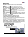
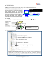
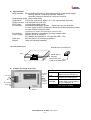
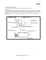
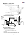
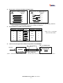
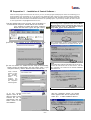
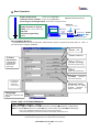
Flash memory MCU On-board Programmer
FLASH1 User’s Manual
Windows95, 98
- Please read this carefully before using the product -
F-ZTATTM is a trademark of Renesas Electronics.
Windows 95 and Windows 98 are products of Microsoft Corporation.
HokutoElectronic Co., Ltd.
REV.2.0.2.0
--- Contents ---
●
GENERAL PRECAUTION
2
●
FLASH1 OUTLINE
3
●
CONTENTS
3
THE PROVIDED CD INCLUDES
3
SPECIFICATIONS
4
FLASH1 THE IMAGE OF THE CASE
4
BATTERY HOLDER GUIDANCE
PREPARATION 1
5
- CONNECTOR & CABLE –
6
FLASH1 INTERFACE CIRCUIT DIAGRAM
6
REFERENCE CIRCUIT DIAGRAM FOR TARGET BOARD
6
SIGNAL-NAME OF REQUIRED RS232C STRAIGHT CABLE
7
SIGNALS BETWEEN FLASH1 AND TARGET BOARD
7
CABLE-CONNECTOR-TYPE-NAME BETWEEN TARGET BOARD AND FLASH1
7
●
PREPARATION 2
●
BASIC OPERATION
- INSTALLATION OF CONTROL SOFTWARE –
8
9
HokutoElectronic FLASH1 User’s Manual
-1-
●
General Precaution
Make sure that you fully understood this user’s manual, before using the FLASH1 and power adapter.
Reading the manual is the responsibility of the FLASH1 users to fully understand all the matters.
● Make sure that you fully understood this user’s manual, before using
WARNINGS
Failure to adhere to the following
warnings may result in possible
heat, smoke and fire damage to
FLASH1 and surrounding systems.
1. Don't disconnect and don't
reconnect power cables while
power is on.
2. Don't remove and don't replace
any circuit while power is on.
3. Don't use power voltages other
than what is specified in circuit
diagram.
4. Be sure to use the correct
connector cables when connecting
between FLASH1, MCU and
peripheral systems.
the FLASH1. Please keep this manual for feature reference.
● This manual describes the specifications and the usage of FLASH1,
and also the provided CD. It does not include the user systems.
● FLASH1 is made up of a programming writer which rewrites programs
to a Flash ROM built-in microcomputer made by Renesas Electronics
Corp. FLASH1 is not to be used for any other purpose other than that
which is specified in the manual.
● The Designs, functions and specifications of this product are subject to
change without notice in order to improving its performance and safety.
● This manual and the product are protected by copyright and the
industrial property right, and all rights are the property of HokutoDenshi
Co., Ltd. All rights are reserved.
● Hokuto Denshi Co., Ltd. has no responsibility for damages and
dangers that may come about from incorrect use of FLASH1. All
incorrect usage's and subsequent warnings against these usages, that
may not have been thought, are the responsibility of the users of
FLASH1 who use FLASH1 according to the usage as is specified in the
manual.
This guarantee is not valid in the following cases.
1.Fire, earthquake, flood, an accident caused by a third party, etc.
2.Incorrect use, misuse, abuses user mistake and / or use in an improper environment.
3.The product has been altered in any way or tampered with.
4.The method of use has resulted in damage to the product, or a defect with the product.
LIMITED GUARANTEE
Hokuto Denshi Co., Ltd. guarantees that the FLASH1 can be used by the usage described in this manual by Hokuto
Denshi Co., Ltd., and guarantees that FLASH1 has been produced correctly and is free of any defects per the
products specification. FLASH1 is guaranteed for 1 year after purchase.
General Disclaimer
Hokuto Denshi Co., Ltd. guarantees the product only when the product is used correctly as described in the manual.
This guarantee is not valid if the product is misused for purposes other than that specified in the manual. The
guarantee is valid only for the materials used to construct the product. Hokuto Denshi Co.,Ltd accepts no
responsibility for whatever costs associated directly (or indirectly) with damaged (or faulty) goods. This guarantee is
valid for only the original purchaser of the product. Any application for retailing the product by a third party cannot be
accepted. The purchaser of the product assumes all responsibility after FLASH1 purchase. The guarantee is not
valid for the secondary product.
The prices of FLASH1 and the attachments are subject to change without prior notice.
Stand-alone onboard programmer
Onboard programmer for VPP12V MCU
FLASH MATE 12V1
Onboard programming in boot mode for dual power supply MCU likewise FLASH1.
●
It allows you to program the target MCU from data ROM without PC.
●
Its cable, connector, and supported MCU are compatible with FLASH1.
Control software for 12V1 is MS-DOS.
No need to connect to PC.
Use only switches to write.
HokutoElectronic FLASH1 User’s Manual
-2-
●
FLASH1 Outline
FLASH1 has been designed to program flash memory MCU, made by Renesas Electronics.
This FLASH1 circuit management at writing to
memory is fully automated. Writing to the target
MCU from the user's PC can be carried out without
switch operation smoothly. All of Renesas
Electronics dual power supply flash memory MCU
is available to reprogram on board.
Attached in this kit, the sample software provides
an easy way of confirming the LED movement on
the boards HSB series, of our product. We
recommend smart choice of using HSB as a target.
Boot mode
Start programming after erasing internal ROM
PC
FLASH1forWin
RS232C
Straight
cable
FLASH1
Target board
Flash MCU
MOT
Contents
Package
The product is packed in the white box. (The box size is 212×277×62mm)
Notification papers
Cardboard
Provided CD
Cardboard
FLASH1
Provided cable
Provided adapter
The PDF manual is recorded in
the provided CD.
The provided CD includes
Installation file for English OS
Double click (When using in English)
Manual (English PDF manual)
Installation file for Japanese OS
Double click (When using in Japanese)
Demonstration (Categorized by HSB)
Support file
Manual (Japanese PDF manual)
About Demonstration Program
Attached CD also includes the sample program for HSB series MCU board by HokutoElectronicd. In
“sample” folder of the CD, there are 4 programs for each MCU type ; freqmeta.mot, stopwat.mot,
voltmeta.mot, watch.mot. Please note that all these programs are in Japanese. All comments will be
displayed correctly with Japanese OS>
HokutoElectronic FLASH1 User’s Manual
-3-
Specifications
MCU available: All the Renesas Electronics flash memory MCU of dual power supply
H8/538F・H8/539F・H8/3644F(H8/3642RF・H8/3643F)
H8/3048F・H8/3334YF・H8/3337YF・H8/3434F・H8/3437F
Programming mode: Only in boot mode
Target MCU:
FVPP=12V (UserVcc is within 2.5~5.5V. Vpp terminal is 60 mA.)
Target interface: IL-S-8S-SS2C2-S (JAE, 8P)
File Format:
S format files (Motorola file)
PC available:
Windows95/98Japanese version - Some types are not available –
In some types of NEC PC-98sereis, Maximum Bit Rate Adjustment does
not work and the instruction halts.
※Please do not operate other applications at the same time.
PC interface:
Power Supply:
Case size:
Weight:
RS232C-serial-port (connecting by using straight cable)
Adapter (DC9V is required)
Or 2 alkaline dry batteries of 1.5V type AA (LR6 / 1.5V)
89×134×36mm (not including projection.)
180g (not including batteries.)
The serial number place.
※Serial seal on provided CD.
Seal
Serial seal on
front box
FALSH1
Back of the case.
Inside of the battery box.
FLASH1 The image of the case
LED state
From target
board
From PC
USER VCC
RS232C
port
When power is supplied from
target board, this LED lights up.
VPP
When VPP ( 1 2 V ) is
supplied, this LED lights up.
When power is supplied
durign USER VCC is lighting
up, this LED lights up.
DSUB25P
Female
connector
MIL standard
Boxed plug
10P
POWER
Both batteries and AC adapter can be used as a
power supply for FLASH1.
AC adapter
HokutoElectronic FLASH1 User’s Manual
-4-
Battery Holder Guidance
Please read <Precaution> before placing the batteries into the battery holder.
<Precaution>
Some of the alkaline batteries contain flexible insulating label to it. When placing that kind of batteries
into the battery holder, negative terminal (-) of the battery holder could come into contact with positive
terminal (+) inside of the flexible insulating label as shown in the diagram below. It causes electrical
short-circuit.
Please do not use the batteries described above. Electrical short-circuit may cause smoke and fire.
HokutoElectronic FLASH1 User’s Manual
-5-
●
Preparation 1
- Connector & Cable –
FLASH1 Interface Circuit Diagram
FLASH1 programming
interface (10P)
Target board
programming
interface
(8P)
ILS8S
Provided target
cable
Reference Circuit Diagram for Target Board
USER VCC
TXD
RXD
USER VCC
USER VCC
VPP
1
2
USER VCC
3
12KΩ
USER VCC
4
5
1UF
0.1UF
6
7
8
GND
ILS8P
RESET
Flash
memory
MCU
GND
12KΩ
Programming
Interface
(8P)
G1
TXD
RXD
RES
VIN
VPP
MD
J1 G2
…High
…Low
12KΩ
◆Test port
When programming
When executing user program
12KΩ
H8/3644F is different at the points below
◆Port name
① PP→P90
② MD→TEST
MD
F-ZTAT
CPU
RESET
GND
GND
GND
Advice for Making Target Board
1. FLASH1 Vpp electrode capacities are 60mA as maximum.
2. Please note that MD port
3. RESET is supposed to be driven with open collector.
4.
5.
6.
Send FLASH1 reset signal to MCU reset port with no delay.
Connect manual RESET with AND parallel circuit or Wired-or.
TXD, RXD must be transmitted at TTL level. RS232C converted signals may be arranged into reverse.
About User VCC
Connector No.5 VIN on programmer side and USERVCC on target board need power supplied to work.
Resistor volume in reference circuit diagram can be adjusted over 10kΩ~47kΩ.
HokutoElectronic FLASH1 User’s Manual
-6-
Signal-name of Required RS232C Straight Cable
PC9801with 25 pins connector
PC
25pins
programmer
1
2
3
4
5
6
7
20
1
2
3
4
5
6
7
20
DOS/V series with 9 pins connector
25pins
PC
9pins
programmer
2
3
4
5
6
7
8
2
3
4
5
6
7
20
25pins
Caution! :The no.4 & 5 lines of the programmer side must be connected appropriately, because
of the importance for the steady control form “FLASH1 for Windows”.
Signals Between FLASH1 and Target Board
FLASH1 side
Signal name
Pin number
1
GND
2
GND
3
RXD
4
TX
5
RESET
6
VIN
7
FVPP
8
MD
9
GND
10
GND
Target board side
Signal name
Pin number
Directions
GND
TXD
RXD
RES
USERVCC
Vpp
MD
GND
USER VCC is consumed
about 10mA at FLASH1.
1
2
3
4
5
6
7
8
Cable-connector-type-name between Target Board and FLASH1
JAE
IL-S-8S-S2C2-S
JAE
IL-S-8P-S2L2-EF
Red line is1P
RS232C
Target Board
FLASH1
OKI FL10A2MA
※OKI・・・OKI Electric Cable Company, Limited.
OKI FL10A2F0-KN
Both OKI (Electric Cable Company,lmd) are MIL standard box connectors.
HokutoElectronic FLASH1 User’s Manual
-7-
●
Preparation 2
- Installation of Control Software –
When the setup program finds the same file name in your PC, the setup program will display the caution recommending you to
avoid overwriting. We recommend you to use the file of the install-disk. When using this control software without overwriting,
guarantee is not valid. And also we can’t guarantee any reflections happened to other applications that well worked before this
installation. Refer to the Windows95 / Windows98 manuals for PC operating system. If you have any troubles, feel free to contact
us. Our support desk is [email protected]
①Set the attached CD into the CD drive, open the “Explorer” to
find the start file “setup.exe”. Double click the icon of the file.
If the message for MDAC files shows, install the
MDAC files first before ②(see the right column)
How to install MDAC files
The message below is appeared in the case that MDAC
(Microsoft Data Access Components) files were not
installed in the PC. Click ”ok”, and follow the below to
set up ”Mdac_typ.exe” in the attached CD.
Double Click
②The start window appears at first, click the buttons ”Next”.
③In the next window, the installer find the setup file automatically.
Please confirm the install folder, click the buttons ”Next”. If you
change the directory, click the “Browse” button to find the one.
step1
Click in double “Mdac_typ.exe” to start installation. To make
an agreement, check the box at the below and click “次へ”.
step2
The window below indicates that MDAC files are all set up.
Confirm the radio button how to reset the PC, click the
“完了”(complete), and continue to the FLASH2 installation
after reset the PC.
Install windows
appear to show
the
progress.
Click the “Next”
button
to
continue
the
installation until
the completion
window appears.
Reset PC immediately
Reset PC later
After the completion window, the window
below appears when the PC requests reset,
select “はい” to make installation effective.
⑤ At this window
appears when all the
files for FLASH1 control
software are set up
appropriately, click the
button “Close” to end
the installation.
FLASH1
It is necessary to reset the PC to make install effective.
Yes
HokutoElectronic FLASH1 User’s Manual
-8-
●
Basic Operation
Prepare target board
Please refer to preparation 1
HSB board can be used as it is.
Install the control software Please refer to preparation 2
Connecting PC and target board Please refer to the diagram below
①
②
Execute the software
Supply the power to objects
Setting (MCU ・communication rate)
Select file
Complete programming
Finish
③
④
⑤
⑥
⑦
Power In
AC adapter or Dry batteries
PC
FLASH1forWin
RS232C
Straight
cable
Target cable
FLASH1
Target board
Power
ON
Flash memory MCU
Start FLASH1forWindows
FLASH1forWindows can execute with select “Hokuto Denshi” group in “Program” from pull-up menu of “Start” , if
you had nothing to change in installation.
③Select
File
①Select COM Port
②Select
parameters ;
④Start Writing
Initial Bit Rate
and Maximum
Bit Rate and
MCU type.
/Stop Writing (while writing)
⑤Exit
Close FLASH1forWindows
⑤ Help
Operations
and Trouble Shootings
Log Information
is appeared
here about
recent writing.
Optional Verify
At the end of writing,
progress
continues
to
verify by check sum.
Language
Select from Japanese and
English.
Check “Help” of FLASH1forWindows
Help in FLASH1 for Windows -contents●At Beginning●Feature●Specifications●Connections and Advices●Preparation of Target Board
●Basic Operation●Writing Flow of FLASH1●Timing Chart in Start of Boot Mode●Error Messages
Lack of Vpp Voltage/Bit Rate Adjustment Error/ Invalid Code Accepted/
Erase Error/Flash Memory Erase Error/Invalid File Format/Data Transmission Error
Caution!! Sample programs are not automatically copy at the installation of the control software.
We recommend copying at first, if you need confirm the connections.
HokutoElectronic FLASH1 User’s Manual
-9-
Other Expendable Supplies
Expendable Supplies Name
AC 100 volt Adapter
FLASH1 Target Cable (10p)
Price
¥2500
¥1200
Notes
Verified only in Japan
Available for FLASH MATE 12V1
Please confirm about the charges for above.
Please visit our web site for the latest information.
http://www.hokutodenshi.co.jp
For technical support
[email protected]
FLASH1 USER'S MANUAL–ForWin– ©2000-2013 北斗電子 Printed in Japan
HokutoElectronics Co., Ltd.
株式会社
phone+81-011-640-8800 fax+81-011-640-8801
e-mail:[email protected] (Technical support),
URL:http://www.hokutodenshi.co. (For Japanese)
Jul. 23, 2012 REV2.0.2.0 (131212)
3-7, Odori-nishi 16, Chuoku Sapporo Hokkaido, 060-0042, Japan
[email protected] (Order and Inquiry)
HokutoElectronic FLASH1 User’s Manual
-10-