1
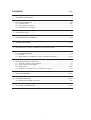
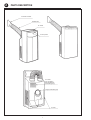
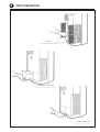
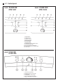
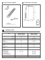
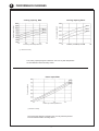
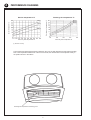
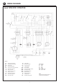
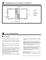
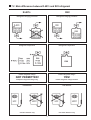
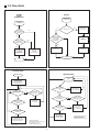
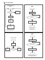
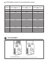
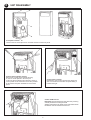
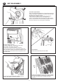
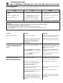
Service
manual
Portable air conditioners
51AKA 006
51AKB 006G
51AKM 006G
51AKB 008G
RTB 165G
RTE 165G
RTB 205C
VTB 075C
Contents
page
1. ASSEMBLY DRAWINGS .......................................................................................... 3
2. PARTS DESCRIPTION .......................................................................................... 4/5
2.1 Control panel .................................................................................................. 6/7
2.2 Accessories supplied ........................................................................................ 8
2.3 Dimensions and weight .................................................................................... 8
3. TECHNICAL DATA .................................................................................................... 8
4. PERFORMANCE DIAGRAMS ............................................................................. 9/10
5. WIRING DIAGRAMS .......................................................................................... 11/13
6. REFRIGERANT CIRCUIT PRINCIPLE OF OPERATION ..................................... 14
7. R-407c REFRIGERANT .......................................................................................... 14
7.1 General ............................................................................................................ 14
7.2 Main differences between R-407c and R22 refrigerant ........................... 15/16
8. MICROPROCESSOR CONTROL .......................................................................... 17
8.1 Special functions of the buttons ..................................................................... 17
8.2 Logic connection diagram .............................................................................. 17
8.3 Flow charts ................................................................................................. 18/20
8.4 Resistance values of room temperature sensor ........................................... 21
9. UNIT DISASSEMBLY ......................................................................................... 21/24
10. TROUBLESHOOTING ....................................................................................... 25/28
10.1 Component testing procedure ........................................................................ 29
11. OPTIONAL ACCESSORIES .............................................................................. 30/31
2
1
ASSEMBLY DRAWINGS
mod. 51AKB 006G
51AKB 008G
RTB 165G
RTB 205C
mod. VTB 075C
mod. 51AKA 006
mod. 51AKM 006G
RTE 165G
3
2
PARTS DESCRIPTION
Exhaust air outlet
Flexible duct
Air outlet
Control panel
Air outlet
(for ventilation,
dehumidification
and heating only)
Supply cable with plug
Air inlet
4
2
PARTS DESCRIPTION
Air filters
Condensate collection tank
Condensate drain tube
5
2.1 Control panel
mod. 51AKB 006
RTB 165F
mod. 51AKB 06G
RTB 165G
1.
2.
3.
4.
5.
6.
7.
8.
9.
10.
11.
12.
OFF position
Mode selector
TURBO cooling
SILENT cooling
Dehumidification
Low fan speed
High fan speed
Ventilation function indicator light
Cooling indicator light
Dehumidification indicator light
Full water tank alarm indicator light
Thermostat
mod. VTB 075F
VTB 075G
1.
2.
3.
4.
5.
6.
ON - OFF push button
Cooling - fan only push button
Thermostat
ON and alarm indicator light
Dehumidification push button
High - low speed fan push button
6
2.1 Control panel
mod. 51AKM 006
51AKM 06G
RTE 165F
RTE 165G
1.
2.
3.
4.
5.
6.
7.
8.
9.
10.
11.
12.
13.
14.
15.
16.
ON-OFF button
Mode selector
Temperature setting button
Fan speed setting button
Operation on timer
Operation off timer
Low fan speed LED
High fan speed LED
ON timer LED
OFF timer LED
Display of set temperature and
programmed operating times
Set temperature LED
Heating LED
Dehumidification LED
Cooling LED
Fan only LED
mod. VTE 075F
VTE 075G
7
2.3 Dimensions and weight
2.2 Accessories supplied
kg
1. Air outlet vent
2. Flexible hose
3. Fastening strap with suction cup
3
27.5
TECHNICAL DATA
Model
51AKB 006 / 51AKB 06G
RTB 165F / RTB 165G
VTB 075F / VTB 075G
51AKM 006 / 51AKM 06G
RTE 165F / RTE 165G
VTE 075F / VTE 075G
Cooling capacity
W
(Btu/h)
1830
6300
1830
6300
Heating capacity
W
(Btu/h)
-----
1000 + 1000
3410 + 3410
750
--640
750
1000 + 1000
640
16
16
3.3
--2.9
3.3
4,35 + 4,35
2.9
1.1
0.8
1.1
0.8
88.9 - 1320
72.2 - 1100
------111.1 - 1100
88.9 - 1320
72.2 - 1100
88.9 - 1320
72.2 - 1100
138.9 - 1320
111.1 - 1100
16
16
Power input
– cooling
– heating
– dehumidification
W
Locked rotor amps
A
Operating current
– cooling
– heating
– dehumidification
A
Dehumidification rate
– cooling
– dehumidification
l/h
Air flow
(fan speed) l/s - rpm
– high-speed cooling
– low-speed cooling
– high-speed heating
– low-speed heating
– high-speed dehumidification
– low-speed dehumidification
Recommended fuse size
A
230V - 1 - 50Hz
Supply voltage
8
4
PERFORMANCE DIAGRAMS
Cooling capacity, Btu/h
80% (1)
Cooling capacity, Btu/h
Cooling capacity, Watt
Cooling capacity, Watt
80% (1)
60% (1)
40% (1)
Indoor dry bulb temperature °C
60% (1)
40% (1)
Indoor dry bulb temperature °C
(1) Relative humidity
The cooling capacity diagram is based on the room dry bulb temperature
for three different relative humidity values.
Power input, Watt
Power input, Watt
80% (1)
60% (1)
40% (1)
Indoor dry bulb temperature °C
(1) Relative humidity
The power input diagram is based on the room dry bulb temperature
for three different relative humidity values.
9
4
PERFORMANCE DIAGRAMS
Suction temperature °C
Discharge air temperature °C
80% (1)
60% (1)
40% (1)
Discharge air temperature °C
Suction temperature °C
80% (1)
60% (1)
40% (1)
Indoor dry bulb temperature °C
Indoor dry bulb temperature °C
(1) Relative humidity
The air discharge temperature diagram is based on the room dry bulb temperature and relative humidity.
Due to the temperature differences of the air at the outlet, the thermometer must be placed exactly in
the position shown in the sketch.
Discharge air temperature measuring point
10
5
WIRING DIAGRAMS
mod. 51AKB 006 / 51AKB 06G
mod. RTB 165F / RTB 165G
Legend
“RS” CONTACT POSITIONS
POSITION
CONTACT
CPS
WS
Power supply cable
Full tank switch
CM
Compressor
CC
Compressor capacitor
IFM
IFC
Indoor fan motor
Indoor fan capacitor
TAF
Antifreeze thermostat
CDP
TA
Condensate drain pump
Room thermostat
CWT
Compressor overload protector
RS
X1
Rotary switch
Terminal block
C1
Indoor fan connector
C2
Pump connector
C4
C5
Top panel connector
Compressor connector
11
Wire colours
O
A
B
R
C
W
G
Y-G
Orange
Brown
Blue
Red
Black
White
Grey
Yellow-Green
Note:
The connection sequence does not
represent the physical layout.
5
WIRING DIAGRAMS
mod. VTB 075F / VTB 075G
Legend
CC
Compressor capacitor
CDP
CM
Condensate drain pump
Compressor
CPS
Power supply cable
CWT
C1
Compressor overload protector
Indoor fan connector
LB
TA
Lamp board
Room thermostat
WS
Full tank switch
X1
SW1
Terminal block
On-off switch
SW2
Fan speed change switch
SW3
SW4
Heat-cool switch
Dehumidifier switch
Electric heater
C2
Pump connector
C3
Compressor connector
C4
C6
Heater connector
Lamp board connector
HTR
IFC
Indoor fan capacitor
IFM
Indoor fan motor
F1
TAF
ST
Safety thermostat
Thermal fuse
Antifreeze thermostat
12
Wire colours
A
B
G
R
W
Y-G
Bk
Brown
Blue
Grey
Red
White
Yellow-Green
Black / Nero
Note:
The connection sequence does not
represent the physical layout.
5
WIRING DIAGRAMS
mod. 51AKM 006 / 51AKM 06G
mod. RTE 165F / RTE 165G
mod. VTE 075F / VTE 075G
Legend
CPS
Power suppply cable
NTC
Air sensor
Wire colours
TAF
HTR
Antifreeze thermostat
Electric heater
CB
Control board
CC
Compressor capacitor
PB
C1
Power board
Compressor connector
A
B
R
O
C
W
G
V
Y-G
IFM
Indoor fan motor
C2
Pump connector
WS
CWT
Full tank switch
Compressor overload protector
C4
C5
PB connector
Indoor fan connector
HTP
Heater thermal protector
C6
Heater connector
IFC
CDP
Indoor fan capacitor
Condensate drain pump
C7
C8
CB connector
CB connector
Terminal block
C9
CB connector
X1
CM
Brown
Blue
Red
Orange
Black
White
Grey
Violet
Yellow-Green
Note:
The connection sequence
does not represent the
physical layout.
Compressor
13
6
REFRIGERANT CIRCUIT PRINCIPLE OF OPERATION
1.
2.
3.
4.
5.
6.
7.
8.
9.
10.
7
Compressor
Condenser
Fan
Filter
Capillary tube
Evaporator
Gas discharge
Liquid
Liquid/gas
Gas suction
R-407c REFRIGERANT
7.1 General
51AKB06G, 51AKM06G, RTB165G, RTE165G, VTB075G
and VTE075G units use the new refrigerant R-407c.
• Residual refrigerant in the system will have to be pulled
out and stored in a disposal cylinder (do not ventilate in
ambient).
R-407c is a blend of three basic constituents: R32, R125,
R-134a with respectively weight composition 23%, 25%,
52%.
• Refrigerant charge will have to be done only with
liquid phase in order to guarantee proper refrigerant
composition inside the system; this can be done or using
dedicated cylinders with two valves (one for liquid, the
other for vapour) or in case of one valve cylinder, put
cylinder in up side down position.
R-407c is an HFC refrigerant that does not destroy ozone
layer.
General behaviour of R-407c systems is very similar to
standard R22 one; system differences linked to R-407c
are below:
• In case of too much refrigerant charged, it is dangerous
to remove partially the charge; this could change
refrigerant composition inside the sistem; in such case it
is suggested to remove completely the refrigerant
charge, pull vacuum again and recharge the sistem with
proper amount of refrigerant.
Since R-407c is a zeotropic blend, during phase change,
liquid composition is different from vapour one; for this
reason in case of leakage in zones with biphase, residual
refrigerant composition could be changed.
R-407c phase changes are not at constant temperature as
in R22 case, but with increasing temperature during
evaporation and with decreasing temperature during
condensation (Glide effect).
In case of refrigerant recharge, in order to assure correct
composition two following steps will have to be followed:
Leak detection will have to be carryed-out only with HFC
sensitive leak detector.
Even if R-407c refrigerant is ozone friendly, do not ventilate
it in the ambient because its warming effect is not zero.
For all other technical details see standard rooles for R22.
14
7.2 Main differences between R-407c and R22 refrigerant
R-407c
R22
Refrigerant charging procedure
Refrigerant charging procedure
Refrigerant composition
Refrigerant composition
Partial refrigerant charge:
Partial refrigerant charge:
NOT PERMITTED!
YES!
Complete refrigerant charge only.
Partial refrigerant charge allowed.
Leak detector
Leak detector
Use HFC detector only.
Use HCFC detector only.
15
7.2 Differences between R-407c and R22 units
R-407c
R22
Temperature trend in evaporator
Temperature trend in evaporator
Temperature trend in condenser
Temperature trend in condenser
16
8
MICROPROCESSOR CONTROL
8.1 Special functions of the buttons
Table 1
Pressing two buttons at the same time it is possible to activate
some functions which are NOT described in the Instruction
Manual.
Test
Activated function
Duration
1
electric heater + LOW SPEED
fan (only for models with
electric heaters)
7 seconds
Self-Test
If the
and “fan speed” buttons are pressed simultaneously
the sequence outlined in the table 1 will start.
Press any button to leave the Self-Test mode. At this point the
unit will automatically enter the maximum cooling mode.
2
Reset
3
If the Timer On and Timer Off buttons are pressed
simultaneously the unit will return to the same condition it was
in just after the first time the plug was connected to the socket:
cooling mode, hi-speed fan and 22 °C room temperature set
point.
Provided the pressure difference between discharge and
suction is acceptable (because the compressor worked for
few seconds), it is possible to restart the unit in this way even
if three minutes have not yet elapsed from the previous stop.
4
5
LOW SPEED
fan
7 seconds
HI SPEED
fan
7 seconds
compressor +
HI SPEED fan
(dehumidification)
7 seconds
compressor
+ HI SPEED fan
condensate drain pump
(maximum cooling WITHOUT
thermostat)
continuous
8.2 Logic connection diagram
Low
speed
LED
Tank
micro switch
Pump
Fan
High
speed
LED
Feed back
TRIAC
Timer ON
LED
Timer OFF
LED
Temperature
LED
Heating
LED
Dehumidification
LED
Cooling
LED
Fan only
LED
DISPLAY
MICROPROCESSOR
TR1
Pump
TRIAC
TR3
High speed
TRIAC
Control
circuit
TRIAC
TR4
Low speed
TRIAC
Fan speed
button
Timer ON
button
Timer OFF
button
Temperature
set button
Operating
mode button
ON / OFF
button
Air
sensor
DC + 5V
RELAY CONTROL CIRCUIT
DC +12 V
DC
+12 / +5V
CONTROL PCB
AC + 12V
RELAY 3
compressor
RELAY 2
heater 2
TRANSFORMER
RELAY 1
heater 1+2
POWER PCB
Compressor
Heater 2
Heater 1+2
NEUTRAL
LIVE
POWER SUPPLY
17
8.3 Flow charts
ON/OFF
POWER
PLUG
CONNECTED
ON/OFF BUTTON
IS PRESSED
PLUG
CONNECTED
NO
UNIT IS OFF
YES
DISPLAY IS
ACTIVATED
NO
VALID
FUNCTIONS
MEMORY
YES
UNIT WAS ON
WHEN PLUG
WAS REMOVED
ON/OFF BUTTON
IS PRESSED
FOR 1 SECOND
MINIMUM
NO
5 SECONDS
DELAY
YES
YES
UNIT IS ACTIVATED
IN THE SAME MODE
AS BEFORE
THE PLUG
WAS REMOVED
SWITCH OFF
A POINT
APPEARS
ON THE DISPLAY
SWITCH ON
STOP
STOP
COOLING MODE
HEATING MODE
START
START
FAN STARTS AT THE
SELECTED SPEED
THE SELECTED
TEMPERATURE APPEARS
ON THE DISPLAY
ROOM TEMP. >
SELECTED TEMP.
+1°C
NO
ROOM TEMP. >
SELECTED TEMP. +1°C
YES
NO
ROOM TEMP. <
SELECTED TEMP. –1°C
COMPRESSOR
IS STOPPED
NO
ROOM TEMP. <
SELECTED TEMP.
–1°C
YES
YES
ROOM TEMP. <
SELECTED TEMP.
–2°C
THE UNIT IS FED
FOR MORE THAN
3 MINUTES
NO
ONE HEATER
IS ACTIVATED
AND FAN IS PUT
AT LOW SPEED
YES
BOTH HEATERS
ARE ACTIVATED
AND FAN IS PUT
AT HIGH SPEED
YES
COMPRESSOR AND
CONDENSATE DRAINAGE
MOTOR ARE STARTED
NO
YES
YES
NO
HEATERS ARE
DEACTIVATED
AND FAN IS PUT
AT LOW SPEED
NO
FAN SPEED
IS SELECTED
COMPRESSOR IS OFF
FOR MORE THAN
3 MINUTES
YES
OPERATING MODE IS
SWITCHED ON 5 SECONDS AFTER
THE RELEASE OF THE
“MODE SELECTION BUTTON”
18
IN HEATING MODE THE FAN
SPEED LED SHOWS
THE SELECTED SPEED
AND NOT THE ACTUAL ONE
8.3 Flow charts
DEHUMIDIFICATION
MODE
TIMER
ON *
START
START
ROOM
TEMPERATURE
< 10°C
YES
COMPRESSOR
AND FAN
ARE STOPPED
UNIT IS DEACTIVATED
AND TIMER ON LED
IS SWITCHED ON (m)
NO
NO
“– –” APPEARS
ON DISPLAY
“X” HOURS ELAPSED
FROM TIMER ON
SELECTION
YES
FAN
IS STARTED
AT LOW
SPEED
UNIT IS ACTIVATED
STOP
COMPRESSOR
IS STARTED
* SUPPOSING THAT TIMER ON
WAS SET TO ACTIVATE THE UNIT
AFTER “X” HOURS.
FAN SPEED LED AND
OPERATING MODE ACCORDING
TO SELECTION DONE.
SELECTING DEHUMIDIFICATION MODE
FAN WORKS AT LOW SPEED.
FAN SPEED CAN BE CHANGED LATER.
TIMER
OFF *
START
FAN ONLY MODE
LED IS SWITCHED
ON LOW LIGHT m
START
NO
“– –” APPEARS
ON DISPLAY
“X” HOURS ELAPSED
FROM THE TIMER OFF
SELECTION
YES
LOW
SPEED
NO
HI SPEED
WAS
SELECTED
YES
HI
SPEED
UNIT IS DEACTIVATED
FAN SPEED IS CHANGED
AFTER 1 SECOND DELAY.
STOP
* SUPPOSING THAT TIMER OFF WAS SET
TO DEACTIVATE THE UNIT AFTER “X” HOURS.
TIMER OFF, FAN SPEED LED
AND OPERATING MODE ACCORDING
TO THE SELECTION DONE.
19
8.3 Flow charts
FAULTY SENSOR
DIAGNOSIS
COMBINED
TIMER *
START
START
FAULTY SENSOR
TIMER DEACTIVATED
(IF RUNNING)
X>Y
(DEACTIVATION SCHEDULED
AFTER ACTIVATION)
YES
NO
YES
NO
FAULTY
SENSOR TIMER
WORKING
SEE
TIMER ON
FAULTY SENSOR
TIMER ACTIVATED
TEMP. <25°C OR
TEMP. >75°C
SEE
TIMER OFF
NO
YES
LED ‘°C’
AND DISPLAY
FLASH
SEE
TIMER OFF
SEE
TIMER ON
FAULTY SENSOR
TIMER SCHEDULE
> 1 HOUR
YES
FAULTY SENSOR
TIMER IS DEACTIVATED
STOP
UNIT IS
DEACTIVATED
* SUPPOSING THAT TIMER ON WAS SET TO:
DEACTIVATE THE UNIT AFTER “X” HOURS
ACTIVATE THE UNIT AFTER “Y” HOURS.
STOP
TANK
ALARM
FAN
CONTROL
DIAGNOSIS
START
NO
START
TANK IS FULL
OR NOT CORRECTLY
INSERTED
NO
FAN CONTROL FAULTY
OR
FAN NOT CONNECTED
YES
COMPRESSOR,
CONDENSATE DRAIN
MOTOR,
FAN,
HEATERS,
LED
ARE DEACTIVATED
YES
UNIT IS DEACTIVATED
FAN SPEED LED FLASHES
‘AL’
IS FLASHING
ON DISPLAY
TO LEAVE THE ALARM CONDITION IT IS NECESSARY
TO REMOVE THE PLUG FROM THE POWER SUPPLY SOCKET,
ELIMINATE THE CAUSE OF THE FAULT
AND RE-INSERT THE PLUG IN THE SOCKET.
20
8.4 Resistance values of room temperature sensor
TEMPERATURE
°C
MINIMUM RESISTANCE VALUE
(ohm)
NOMINAL RESISTANCE VALUE
(ohm)
MAXIMUM RESISTANCE VALUE
(ohm)
15
14792
15824
16734
16
14131
15092
15949
17
13505
14399
15206
18
12910
13743
14502
19
12346
13120
13835
20
11809
12530
13203
21
11300
11970
12604
22
10815
11439
12036
23
10355
10934
11497
24
9917
10455
10985
25
9500
10000
10500
26
9103
9568
10039
27
8726
8157
9601
28
8366
8766
9185
29
8024
8394
8790
30
7697
8041
8414
31
7386
7704
8056
32
7090
7384
7716
33
6807
7079
7392
34
6537
6788
7084
35
6279
6511
6791
9
UNIT DISASSEMBLY
Remove the plug from socket.
It is not necessary to remove the exhaust air flexible duct from its housing (two holes).
21
9
UNIT DISASSEMBLY
Front panel removal
Unscrew the six screws placed on unit back and remove the front panel.
Control panel template removal
Remove the control panel template levering
on the two hooks placed in its lower part.
In this way all the electrical and electronic parts of
control panel can be reached and it is also possible
do all checks and parts substitutions of the same
panel.
Control panel removal
Release the control panel pushing the plastic tab
with a screwdriver and extract the panel sliding it
towards the right.
Control PCB removal
Important: Discharge the body static electricity touching
a metal part before touching the PCB.
Slightly pull apart the two plastic body sides which fasten
the PCB in order to release and remove it.
22
9
UNIT DISASSEMBLY
Electromechanical control removal
Remove the plug-in switch knob, release the plastic tab
and remove the switch end the board.
Rear panel removal
Remove the condensate tank in the rear of the unit.
Unscrew the four side clamping screws, lift the back panel about 10 mm and finally remove it.
At this point it is possible to make any check and/or service operation on the unit.
Power PCB replacement
Important: Discharge the body static electricity touching
a metal part before touching the PCB.
Disconnect polarized connector of power PCB.
Then disconnect the four cables complete with terminals.
Push with a sharp tool in the hole in order to release
the PCB from the clamp and to extract it.
23
9
UNIT DISASSEMBLY
Fan motor replacement
Disconnect the polarized electronic connector and TH sensor.
Using a screwdriver release the four plastic tabs that keep
the half scroll of the fan in place.
In this way it is possible to extract the motor from the
rubber vibration isolators which are supporting it.
If one or more plastic tabs of the half scroll of the fan are
broken, the half scroll can be secured by similar screws to
the ones used in the unit, during the re-assembly.
Electric heater removal
(models 51AKM 006, 51AKM 06G, RTE 165F,
RTE 165G, VTE 075F, VTE 075G)
Disconnect the polarized electric connector.
Remove the securing screw, release the plastic tab,
slide the electric heater compartment toward the right
and then remove the electric heater compartment and
the heater itself.
Coil removal
Remove the air flow flap and its holder.
Extract the refrigerant from the unit using a suitable
device and avoiding to exhaust it in the atmosphere.
Unsolder and disconnect coil piping and then
remove it.
Remove the pipe conduit plate releasing the six
plastic tabs which secure it to the unit.
24
10
TROUBLESHOOTING
Mod. 51AKM 006, 51AKM 06G, RTE 165F, RTE 165G, VTE 075F, VTE 075G
Autodiagnostic
In the event of malfunctions, a warning will be given automatically on the display.
SIGNAL
–
flashes on the display and LEDs off
– Display and
LED flashing
– Fan speed LED flashing
CAUSE
REMEDY
– Water tank full or not correctly inserted
– Empty the water tank or check that it is
correctly inserted
– Ambient air thermostat not working
(the unit will operate for 1 hour)
– Replace the room temperature sensor
– Electronic Printed Circuit Board
defective or fan not connected
– Replace the control PCB or
connect the fan
Attention
The operation outlined by * requires momentary connection between parts under voltage
and therefore they must be executed with caution.
In case of difficulties with the connection it is better to replace the power PCB.
If the trouble disappears the problem is solved. If not reutilize the old power PCB and replace
the control PCB.
Trouble
Action
Remedy
Unit does not work at all.
Check the supply voltage.
Call an electrician in case it is more than
15% less than the nominal voltage.
Disconnect connector A on the power
PCB and verify that there are 12 VAC
between the pin A4 and the pin A2
(or between pin A4 and the quick
connector F2).
Replace the power PCB if there are not
12 VAC. If not replace the control PCB.
Verify if Timer On was activated.
Deactivate Timer On pushing the
corresponding button until the message
appears on the display.
The message
blinks on the display
and the LEDs are on (Dehumidification
mode only)
Unit cannot run in the Dehumidification
mode when the temperature is less
than 10 °C.
The message
flashes on display
and the LEDs are off.
Empty the condensate tank or place it
in the correct position.
Check the supply voltage.
Call an electrician in case it is more than
15% less than the nominal voltage.
Check the resistance of air sensor.
Replace air sensor if necessary.
Compressor and fan do not work
in Cooling and in Dehumidification
modes.
Compressor does not work
and the fan is working in Cooling
and in Dehumidification modes.
Check if there is voltage between quick
connector F1 and both the quick
connectors of relay RL3.
If voltage is found, check if compressor
thermal protection is closed.
Replace compressor thermal protector
if necessary.
If compressor thermal protector is okay,
check compressor winding resistance
(see Table 2 of page 57).
Replace compressor if necessary.
* If no voltage is found disconnect
connector A on the power PCB, connect
contact A3 of the power PCB to quick
connector F2 and check if relay RL3 trips
or not.
If relay does not trip it is necessary to
replace the control PCB otherwise the
power PCB.
25
10
TROUBLESHOOTING
Mod. 51AKM 006, 51AKM 06G, RTE 165F, RTE 165G, VTE 075F, VTE 075G
Trouble
Action
Remedy
Unit does not work and both fan
speed LEDs are blinking.
Check the start capacitor.
Replace start capacitor if necessary.
Connect the fan motor directly to the
supply.
Replace the motor in case it does
not work; if motor works replace the
control PCB.
Check the supply voltage.
Call an electrician in case it is more
than ±10% of the nominal voltage.
Check if run capacitor is shorted
or grounded.
Replace capacitor if necessary.
Check the maximum motor speed.
Replace motor in case speed is too low.
Ensure that the coils are clean and their
fins are not damaged.
Clean or straighten the fins.
Check supply voltage
Call an electrician in case it is more than
±10 of the nominal voltage.
Fan motor is continuously
cycled on-off by its built-in
overload protector.
Compressor motor is continuously
cycled on-off by its built-in overload
protector.
Check if air temperature is lower than
maximum allowed one.
The cooling effect is not sufficient.
Check fan speed. (A low speed might
cause discharge pressure increase).
If fan speed is too low at maximum
speed it is necessary to replace the
motor
Ensure that the condenser coil is clean
and its fins are not damaged.
Clean or straighten the fins.
Check compressor and condenser.
Replace it if it does not work.
Check if refrigeration circuit is partially
or totally clogged.
Replace the clogged parts and recharge
the circuit.
Air filter is clogged.
Clean or replace the air filter.
Ensure that the condenser and cooler
coils are clean and their fins are not
damaged.
Clean or straighten the fins.
Compressor motor is continuously
cycled on-off by its overload protector.
See previous trouble.
Refrigerant charge is not sufficient.
Remove the charge, identify and repair
any possible leaks and recharge the
circuit.
Check fan speed when motor is at
maximum speed and supplied right
voltage.
If speed is too low, lubricate with oil the
bearing. If speed is still too low it is
necessary to replace the motor.
Check if refrigeration circuit is partially or
totally clogged.
Replace the clogged parts and recharge
the circuit.
Too much frost on cooler.
See separate section “Too much frost
on cooler”.
Compressor is unable to create the
necessary pressure differential.
Check compressor current and replace
compressor if necessary.
26
10
TROUBLESHOOTING
Mod. 51AKM 006, 51AKM 06G, RTE 165F, RTE 165G, VTE 075F, VTE 075G
Trouble
Action
Remedy
Too much frost on cooler.
Air filter is clogged.
Clean air filter.
Check fan speed.
Replace motor if fan speed is too low.
Outside air temperature is too low.
Put the unit in Fan Only mode until
outside coil is defrosted.
Compressor relay contacts are welded.
Replace power PCB.
Cooler fins are bent and they partially
close the air passage.
Straighten the fins.
Refrigerant charge is not sufficient.
Remove the charge, identify and repair
any possible leaks and recharge the circuit.
Compressor does not work.
See section “Compressor does work
and the fan is working in Cooling and in
Dehumidification modes”.
The charge is too low or has escaped.
Add refrigerant, identify and repair any
possible leaks and recharge the circuit.
Check if refrigeration circuit is partially or
totally clogged.
Replace the clogged parts and recharge
the circuit.
The fan hits the scroll.
Set the fan position in the scroll.
The copper lines vibrate and touch parts
of the unit.
Set the copper line position.
The noise is due to the compressor.
Replace the compressor.
The fan does not work in
Fan Only mode.
Verify if Timer On was activated.
Deactivate Timer On pushing the
corresponding button until the message
appears on the display.
The heater and the fan do not work
in Heating mode
Verify if Timer On was activated.
Deactivate Timer On pushing the
corresponding button until the message
appears on the display.
The heater does not work when fan is
operating at low speed and the low or
high speed was selected.
Remove and insert the plug into the
socket in order to reset PTC protection.
If heater restarts clean filters and fins.
Select high fan speed and set the
thermostat at 27 °C in order to activate
both the stages of the heater.
Clean filters and fins and replace the
heater if fan works at high speed and
only one or none of the heater stages
operates.
Check air temperature sensor.
Replace air temperature sensor if
necessary.
Check if there is voltage between quick
connectors F1 and F4.
Replace the heater, clean filters and fins
if voltage is present.
* Disconnect connector A on the power
PCB, connect contact A5 of PCB to
quick connector F2 and check if the
relay RL2 trips if no voltage is found.
Replace control PCB in case relay RL2
trips; if not replace power PCB.
One of the heater stages does not
work when fan is operating at high
speed and the high speed was
selected.
Check if there is voltage between
quick connectors F1 and F4.
Replace the heater, clean filters and fins
if voltage is present between quick
connectors F1 and F4.
* Disconnects connector A on the power
PCB, connect contact A5 of PCB to
quick connector F2 and check if relay
RL2 trips in case no voltage is present.
Replace control PCB in case relay RL2
trips; if not replace power PCB.
Both heater stages do not work when
fan is operating at low speed and the
high speed was selected.
Check if there is voltage between quick
connectors F1 and F3.
Replace the heater, clean filters and fins
if voltage is present.
* Disconnects connector A on the power
PCB, connect contact A3 of PCB to
quick connector F2 and check if relay
RL1 trips in case no voltage is present.
Replace control PCB in case relay RL1
trips; if not replace power PCB.
Unit does not cool at all.
Unit is too noisy.
27
10
TROUBLESHOOTING
Mod. 51AKM 006, 51AKM 06G, RTE 165F, RTE 165G, VTE 075F, VTE 075G
Trouble
Action
Remedy
The condensate tank is filled
in Cooling Mode.
Place the exhaust air duct in vertical
position and pour a glass of water
on the condensing coil.
Connect the condensate drain pump
directly to the supply.
Replace the control PCB in case
the motor works (the noise of the
drained water can be easily heard).
Replace the motor in case
it does not work.
The condensate tank is properly
positioned and empty, the message
blinks on display in any working
mode.
LEDs are on.
Unit cannot work in Dehumidification
Mode if temperature is lower than 16 °C.
Check the tank microswitch in case the
LEDs are not on.
Replace microswitch if necessary.
Check microswitch wiring.
Restore wiring if open, or replace the
wiring itself if necessary. Replace the
control PCB if the wiring is okay.
Both the display and the LEDs are
off, but the unit is properly working.
Replace the control PCB.
10.1 Component testing procedure (all models)
A) Leaks
Electric conductors
Torch leak detector use
Remove the plug from the socket and check the continuity
of all the conductors and jumpers.
To carry out a leak test of a refrigerant circuit it is
necessary to move the sensor pipe terminal of the leak
detector along all the joints and the parts containing
refrigerant.
Maximum sensitivity of the detector can be obtained by
keeping the flame high enough to get a red copper plate.
The flame is blue if there is no refrigerant in the air.
Available power supply
Low voltage is the most common problem.
Voltage must be read by an accurate and reliable voltmeter
when the unit is working in Cooling Mode. The meter sensors
must be inserted in the sensor in parallel with the unit.
When the sensor pipe draws in air containing refrigerant the
colour of the flame changes according to the concentration
of the refrigerant in the air.
Components tests
In case of a suspected electric fault first test the circuit to
identify the faulty part.
1. A small leak will cause the flame colour to switch from
blue to green.
2. A large leak will cause the flame colour to switch from
blue to violet.
The tests must be carried on using a TESTER suitable for
troubleshooting.
Attention! Do not inhale the fumes of the leak detector
when the sensor pipe is drawing in air heavily polluted with
refrigerant.
Change-over switch
1. Remove the plug from the socket.
2. Insert the tester in the different positions of the changeover switch shown in the wiring diagram to check the
continuity between the contact and the corresponding
position of the change-over switch.
This test must be carried out only when all cables are
disconnected from the change-over switch.
B) Electric parts
In case of a fault of any electric component, to identify the
problem and to solve it apply the procedures described on
the next pages. To carry out these tests it is necessary to
remove unit front panel.
Room thermostat
(mod. 51AKB 006, 51AKB 06G, RTB 165F, RTB 165G,
VTB 075F, VTB 075G only)
1. Remove the plug from the socket.
2. Insert the tester according to the wiring diagram
indication and put the thermostat knob to the maximum
cooling position to check the continuity between
thermostat contacts.
This test must be carried on only when all cables are
disconnected from the thermostat.
Supply cable
Check the voltage at the terminals while the plug is
connected to the socket.
28
10.1 Component testing procedure
Capacitor
body
To each
terminal
Capacitor
To capacitor
body
Capacitor
Fig. 1
Fig. 2
Capacitors
Compressor
Remove the plug from the socket and remove the cables
from the capacitor. Discharge the capacitor, shortcircuiting
its terminal with the blade of a screwdriver.
Take an Ohmmeter and select the x 100 scale. Then
connect the sensors of the Ohmmeter to two terminals of
the capacitor.
a) If the capacitor is in order the needle will go
immediately
to zero and then will indicate high resistance.
b) If the capacitor is shorted the needle will go to zero and
stop in that position.
c) To check if a capacitor with metallic body is shorted it is
necessary to put a sensor of the Ohmmeter in contact
with a terminal of the capacitor and the capacitor body.
If capacitor is shorted the instrument will indicate
the electric continuity.
d) To check the capacitor polarity it is necessary to put the
Ohmmeter terminals on the capacitor terminals,
verifying
that the needle goes to zero and then indicates
the maximum resistance.
Compressor
Before carrying out the test all cables must be
disconnected from the compressor, and its motor must be
checked to be sure that its windings are not shorted and/or
interrupted. Then:
1) Put a lead of the test circuit in contact with the
compressor body in an unpainted area in order to check
the insulation.
2) Put one of the leads on terminal “C” and the other one
on terminal “S” of the compressor in order to check the
continuity of the start winding.
3) Secure one of the leads on the compressor terminal “C”
and the other one on terminal “R” of the compressor in
order to check the continuity of the run windings.
Check that winding resistances correspond to the figures
given in the table 2 and that there is no ground leakage.
Then reverse the position of the Ohmmeter sensor on
the capacitor terminals: the needle will go to zero and
then come back to the normal position.
Air temperature sensor
(mod. 51AKM 006, 51AKM 06G, RTE 165F, RTE 165G,
VTE 075F, VTE 075G only)
In this way the capacitor will be discharged and then
recharged by the Ohmmeter battery.
Disconnect the sensor and using a tester in Ohmmeter
mode check that the sensor resistance corresponds to the
figure stated in the table on page 21.
Compressor thermal overload protection
The test of the compressor thermal overload protection
(Klixon) must be carried on before the continuity test;
remove the plug and the connection cables from the
thermal overload protection. Be sure that the protection is
cool and closed. If necessary the Klixon must be removed
from the compressor body and cooled before the test.
Fan motor
Before the test it is necessary to rotate the fans by hand to
ensure that their bearings are not seized and their wheels
do not touch the housing.
Table 2
Winding resistance at 25°C
Remove the plug and check the run capacitor to be sure
that it is properly working; then:
1) Connect the motor with the run capacitor directly in the
circuit. If the motor does not work it has to be replaced.
2) In case the motor works but the current drawn is too
high it is necessary to see if the motor is shorted
checking all connecting cables.
29
Compressor
C-R
C-S
4.81 Ω
7.08 Ω
Fan
White - Grey
White - Blue
125 Ω
146 Ω
OPTIONAL ACCESSORIES
Window installation
Wall installation
300
1200
11
30
11
OPTIONAL ACCESSORIES
Filter kit
Activated carbon filter
Electrostatic filter
31
Filter frames
L010119H31 - 0397
Carrier S.p.A. - Via R. Sanzio, 9 - 20058 Villasanta (MI) Italy - Tel. 039/3636.1
The manufacturer reserves the right to change any product specifications without notice.
Order No. 15173-74, March 1997. Supersedes Order No. (new).
Printed in Italy