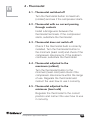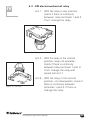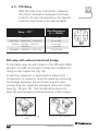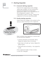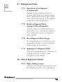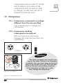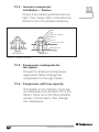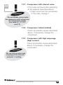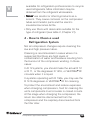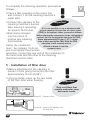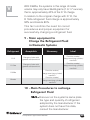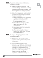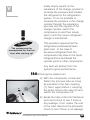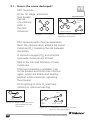
1
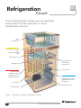
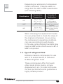
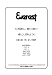
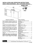
Compressor
Application
Manual
This manual may not be reproduced in whole or part
without prior permission from EMBRACO.
Index
Page
I. Introduction ........................................................... 03
II. Refrigeration circuit ............................................... 04
III. Hermetic compressor ............................................ 06
IV. Diagnosing the problem ........................................ 11
V. Procedure for changing the
hermetic compressor ............................................ 34
VI. Further important recommendations ..................... 46
VII. Further information ................................................ 64
Compressor Application Manual
1
2
Compressor Application Manual
I
Introduction
Dear refrigeration professional!
Since its incorporation in March 1971, Embraco
has been doing its utmost to keep an ever closer
relationship with its customers. This relationship
has been translated in its commitment to
continuously provide timely technical information
that contributes further to the professional knowhow of our refrigeration professional partners.
The purpose of this Manual is to facilitate your
work. It is a valuable aid to solving problems in the
refrigeration system. You will find that you rarely
need to change a hermetic compressor. Generally
the faults are in other parts of the system.
If, however, you do need to substitute the
compressor, this Manual will help you do so step by
step, even if you do not have all the equipment.
The Manual also gives some tips on how to prolong
the working life of the hermetic compressor.
The information is easy to understand and useful.
Always keep this Manual in your pocket.
Wishing you success in your work... and many
satisfied customers.
For further information, consult our site on the
Internet, at the following address
www
.embraco.com.br
www.embraco.com.br
.embraco.com.br.
Compressor Application Manual
3
II
Refrigeration
Circuit
The following figure shows you the essential
components for the operation of most
refrigeration circuits.
Main
evaporator
Refrigerant fluid in
liquid
and/or blended
form
Discharge line
Cold plate or
Secondary
evaporator
Condenser
Suction line
Superheated
refrigerant fluid
in gaseous form
(high pressure)
Refrigerant fluid in
gaseous form (low
pressure)
Filter drier
Capillary tube
Compressor
Figure 1 - Operation of a basic refrigeration system
4
Compressor Application Manual
II
We will show below how a basic refrigeration
system works:
The compressor draws in the refrigerant fluid from
the evaporator by reducing the pressure in this
component. The fluid is compressed by the
compressor and moves to the condenser. In the
condenser the refrigerant fluid under high pressure
releases heat to the environment and becomes
liquid. The next component of the circuit is the
control device, which may be a capillary tube or an
expansion valve. The control element reduces the
pressure of the liquid refrigerant which was formed
in the condenser. This drop in pressure permits the
refrigerant to evaporate at low temperatures and
return to the gaseous state when passing through
the evaporator.
The change from a liquid to gaseous state requires
heat. So the refrigerant fluid removes the heat from
inside the refrigeration system through the
evaporator. The condenser releases this heat into
the environment. The control element offers a certain
resistance against the refrigerant's circulation,
separating the high pressure (condenser) from the
low pressure (evaporator) side.
The refrigeration system also uses a filter drier
with desiccant to retain any water that may be left
in the system.
The oil cooling tube that exists in some compressors
is used to help reduce the compressor temperature.
Lastly, there are systems that use a suction
accumulator to evaporate any residual liquid
refrigerant, stopping it from returning through the
suction line.
Compressor Application Manual
5
Hermetic
compressor
The compressor is a very important item in the
refrigeration circuit. Its function is to circulate the
refrigerant fluid inside the circuit.
1 - Use of compressors
The choice of a compressor for certain refrigeration
equipment depends on the following factors:
1.1 - Control Device
As mentioned above, every refrigeration
system needs a control device. This may
be an expansion valve or capillary tube.
In capillary-equipped circuits, the
pressures on the suction and discharge
sides are equal when the compressor is
stopped. In this kind of circuit, the
compressor is equipped with a low
starting torque motor.
In an expansion valve circuit, however,
refrigerant only flows through the valve
when the compressor is switched on. So,
the pressure between the suction and
discharge are not equal when the
compressor is stopped. In this case, the
compressor is equipped with a high
starting torque motor.
6
Compressor Application Manual
III
III
The compressor motors appropriate for
these two systems are called:
LST – Low Starting Torque
used in capillary systems.
HST – High Starting Torque, used in
expansion valve systems.
Classification
Control
System
LST
Capillary
Expansion valve
HST
(or Capillary)
Compressors
Indicated
Example of
Application
All Embraco
Refrigerators,
freezers and
compressors
Only compressors
with the letter X in
the code of model
e.g.: FFI 12BX,
FFI 12HBX etc...
drinking fountains
Commercial food
counters, soft
drink machines,
Refrigerated
food counters and
displays and
walk-in refrigerators
HST compressors may be used in
systems using LST (capillary tube)
compressors when the off cycles are shorter,
not permitting equal equalized pressures.
However, LST compressors cannot be used
in expansion valve systems.
1.2 - Evaporation temperature
Another factor influencing the choice of
the compressor is the evaporator
temperature range required by the
system. We now point out two extreme
situations:
• Freezers that work at low temperatures,
varying between -25oC (-13oF) and
-35oC (-31oF).
Compressor Application Manual
7
• Dehumidifier that works at an evaporator
temperature of over 0oC (32oF).
Heat absorption by the refrigerant will
depend on the evaporator temperature.
A certain pressure corresponds to a
certain temperature in the evaporator.
The gas density is higher at low
temperatures and, therefore, only a small
quantity of heat may be absorbed during
evaporation. If there is evaporation at a
higher temperature, for instance, 0oC
(32oF), the pressure and density will
increase and more heat will be absorbed.
For this reason, we can conclude that
the work required by the motor in a
compressor for a high evaporation
temperature will be more than that
required by the same compressor at a
low evaporation temperature.
Consequently, motors to be used in high
evaporation pressure systems must have
a higher operating torque.
The compressors can be classified
according to their use as follows:
HBP – High Back Pressure
High evaporation temperature
MBP – Medium Back Pressure
Medium evaporation temperature
LBP – Low Back Pressure
Low evaporation temperature
8
Compressor Application Manual
III
III
Depending on what kind of compressor
model is involved, it may be used in a
range from the LBP to HBP classification
(see following table).
Classification
Evaporation
Temperature
Example of
Application
LBP
-35oC to -10oC
(-31oF to +14oF)
L/MBP
-35oC to -5oC
(-31oF to +23oF)
Freezers
& Refrigerators
Refrigerated food
counters and drinking
fountains
HBP
-5oC to +15oC
(+27oF to +59oF)
Dehumidifiers, soft drink
machines and drinking
fountains
When choosing the replacement model,
it is very important to check the class of
the original compressor. As you know,
the compressor's operating conditions
can vary according to each design.
In this way, some drinking fountains may
need an HBP while others use an LBP or
MBP compressor.
1.3 - Type of refrigerant fluid
Embraco markets compressors for use
with R 12 and/or blends, R 134a and
R 600a refrigerant fluids.
These compressors differ from each
other inside (motor, pump, oil type,
displacement, etc.) in order to provide
the best performance and guarantee a
highly reliable product.
Compressor Application Manual
9
III
To facilitate identification, there are
special labels on the compressor
informing the refrigerant fluid used.
Figure 3 - Compressor label for
R 600a refrigerant fluid
Figure 2 - Compressor label
Figure 4 - Compressor label for R 134a
refrigerant fluid
!
Since September 1997, Embraco has
approved some refrigerant blends to be
used in its compressors and only those
with the respective label will be
Attention
suitable for the blends.
Blends approved
The blends approved to be
only for use with the
used in the Embraco
R 12 compressors
compressors are FX 56,
MP 39, MP 66 and ISCEON 49.
Figure 5 - Label for Compressors that can use blends
10
Compressor Application Manual
IV
Diagnosing
the
problem
Before changing any part of the refrigeration
system, the good refrigeration professional
undertakes a full diagnosis to identify the real
cause of the problem.
The following table shows the most frequent failures
in a refrigeration system and their possible causes.
For each problem presented, you will find its
possible causes marked with a (•). The problems
are listed in the upper part of the table. Follow
the arrows and you will find a (•) on each
possible cause. In the same line as each cause
you will find the number of the item related to the
necessary actions to correct the problem. Look in
the Manual for the item corresponding to that
action and proceed with care.
Compressor Application Manual
11
Example:
IV
PROBLEM
The refrigerator refrigerates too much
(1st column in Table of Main Refrigerator
Problems - Part 1).
POSSIBLE CAUSE
Wrong connection in connection box
(first (•) in 1st column).
STEPS
Item 2.2. When looking for this item in the
Manual you will find:
Check the connections with the help of
the refrigerator's electrical diagram. If the
connections are correct, go back to the
table and you will find another (•) in the
1st column.
This will be another possible cause of the
problem:
Thermostat does not switch off. You will
find the step to take in the same line (item
4.3). Look in the Manual under this item
and the step will be there: Check if the
thermostat bulb is correctly installed. Turn
the thermostat button to the lowest point
(least cold) and check if the compressor
disconnects. If the problem continues,
substitute the thermostat. If necessary,
you will also find other possible causes
for the problem, always accompanied by
the necessary steps. Try for yourself. You
will see that it is much easier than it looks.
12
Compressor Application Manual
IV
Table of Main Refrigerator
Problems - Part 1
EXCESSIVE REFRIGERATION
INSUFFICIENT REFRIGERATION
ELECTRICAL SHOCK
NOISES
EXTERNAL SWEATING OF THE CABINET
INTERNAL SWEATING OF THE CABINET
HIGH POWER CONSUMPTION
DOES NOT WORK COMPRESSOR DOES NOT SWITCH ON/OVERLOAD PROTECTOR NOT WORKING
DOES NOT WORK COMPRESSOR DOES NOT SWITCH ON/OVERLOAD PROTECTOR WORKING
DOES NOT WORK COMPRESSOR SWITCHES ON/OVERLOAD PROTECTOR WORKING
POSSIBLE CAUSES - ELECTRICAL ORIGIN
MEASURES
See item in Chap. IV
No voltage at power supply
1.1.1
Very low voltage at power supply
1.1.2
Very high voltage
1.1.3
Interrupted electric cable or wiring
2.1
Wrong connection at the terminal board
2.2
Wiring or electrical components touching
metal parts
2.3
Electrical components interrupting the current flow to
the compressor
2.4
Internal light does not switch off
2.5
Inadequate transformer
2.6
Inadequate grounding
3.1
Thermostat switched off
4.1
Thermostat with no current passing through contacts
4.2
Thermostat does not switch off
4.3
Thermostat adjusted to the maximum (coldest)
4.4
Thermostat adjusted to the minimum (least cold)
4.5
Thermostat making noise
4.6
Thermostat with loose bulb
4.7
Thermostat with incorrect bulb position
4.8
Thermostat with failure or irregular operation
4.9
Inadequate thermostat
4.10
Incorrect overload protector
5.1
Faulty overload protector
5.2
Incorrect starting relay / PTC
Faulty starting relay / PTC
Incorrect starting capacitor
6
6.1/6.2/6.3
7.1
Faulty starting capacitor
7.2
Compressor connected to a voltage different from the one specified
19.1
Compressor winding interrupted or burned out
19.2
Compressor with current leakage to the housing
19.3
Compressor with high amperage (high current)
19.9
Compressor Application Manual
13
IV
Table of Main Refrigerator
Problems - Part 2
EXCESSIVE REFRIGERATION
INSUFFICIENT REFRIGERATION
ELECTRIC SHOCK
NOISES
EXTERNAL SWEATING OF THE CABINET
INTERNAL SWEATING OF THE CABINET
HIGH POWER CONSUMPTION
DOES NOT WORK COMPRESSOR DOES NOT SWITCH ON/OVERLOAD PROTECTOR NOT WORKING
DOES NOT WORK COMPRESSOR DOES NOT SWITCH ON/OVERLOAD PROTECTOR WORKING
DOES NOT WORK COMPRESSOR SWITCHES ON/OVERLOAD PROTECTOR WORKING
POSSIBLE CAUSES - MECHANICAL ORIGIN
Condenser improperly fixed - metal tubes touching
8.1
Partial blockage in tubes
8.2
Capillary blockage due to water / wax / paraffin
8.3
Dirty/covered condenser or no air circulation
8.4
Incorrect leveling of refrigerator or compressor base
9.1
Noise caused by other components
9.2
Compressor touching the wall or cabinet
9.3
Poor door sealing
10
Wrong location of the refrigerator
11
Very high relative humidity (over 85%)
12
Refrigerator without freezer tray
13
Refrigerator used in excess
14
Refrigerator used incorrectly
15
Wet Insulation (glass wool)
16.1
Deterioration of or no heat insulation
Expansion of refrigerant in the evaporator
16.2
17.1
Excess refrigerant fluid charge in the refrigerator
17.2
No refrigerant fluid charge
17.3
Leakage of refrigerant fluid
17.4
Use of expansion valve
14
MEASURES
See item in Chap. IV
18
Incorrect compressor installation / fixation
19.4
Compressor inadequate for the system
19.5
Compressor with low capacity
19.6
Compressor with internal noise
19.7
Compressor locked (stalled)
19.8
Compressor Application Manual
IV
1 - Problems and Solutions
1.1 - Voltage
1.1.1 - No voltage at power supply
Check using a voltmeter or test
lamp.
1.1.2 - Very low voltage at power supply
To eliminate problems of voltages
below 103 V (115 V nominal) and
198 V (220 V nominal), at the end
of the Manual we recommend the
use of a voltage stabilizer.
When the compressor does not
start, the problem can be solved
most often by using the right
starting capacitor.
1.1.3 - Very high voltage
To eliminate the problem of
voltages above 132 V (115 V
nominal) and 240 V (220 V
nominal) we recommend the use
of a voltage stabilizer.
2 - Electrical Parts
2.1 - Interrupted electric cable or wiring
Using a test lamp or ohmmeter, check if
the cable or wiring is not interrupted. Also
check the plug.
Compressor Application Manual
15
2.2 - Wrong connection at the terminal board
Check the connections using the
refrigerator's electrical diagram.
2.3 - Wiring or electrical components touching
metal parts
Check if there is a fault in the insulation of
an electrical component that is touching
metal parts. Correct the defect.
2.4 - Electrical components interrupting the
current flow to the compressor
Defect in such components as thermostat,
auxiliary transformer, timer, etc. Check.
2.5 - Internal light does not switch off
Check if the light switch has a problem,
such as a poor contact, incorrectly
installed, etc.
2.6 - Inadequate transformer
Check if the transformer is the one specified
in the table in Chapter VI, item 4.
3 - Inadequate Grounding
3.1 - Electrical discharge
Check the ground connection.
If necessary, redo the grounding.
16
Compressor Application Manual
IV
IV
4 - Thermostat
4.1 - Thermostat switched off
Turn the thermostat button to maximum
(coldest) and see if the compressor starts.
4.2 - Thermostat with no current passing
through contacts
Install a bridge wire between the
thermostat terminals. If the compressor
starts, substitute the thermostat.
4.3 - Thermostat does not switch off
Check if the thermostat bulb is correctly
installed. Turn the thermostat button to
the minimum (least cold) and check if the
compressor disconnects. If the problem
continues, substitute the thermostat.
4.4 - Thermostat adjusted to the
maximum (coldest)
Turn the thermostat button to the
minimum (least cold) and check if the
compressor disconnects within the range
of use. Regulate the thermostat and
instruct the user how to use it correctly.
4.5 - Thermostat adjusted to the
minimum (least cold)
Regulate the thermostat to the correct
position and instruct the user how to use
it correctly.
Compressor Application Manual
17
4.6 - Thermostat making noise
Inform the user that a clicking noise is
normal when the thermostat switches on
and off. In any case, please check
whether the thermostat is correctly
installed.
4.7 - Thermostat with loose bulb
Correctly install the thermostat bulb.
4.8 - Thermostat with incorrect bulb
position
Install the bulb according to
manufacturer's specifications.
4.9 - Thermostat with failure
or irregular operation
Substitute the thermostat.
4.10 - Inadequate thermostat
Check if the thermostat model used is
recommended by the manufacturer. If
necessary, consult the manufacturer of
the refrigeration system.
5 - Thermal Protector
5.1 - Incorrect overload protector
Check if the overload protector is as
recommended. If not, change the start
relay and protector kit for that specified.
If necessary, consult the authorized
wholesaler or Embraco.
18
Compressor Application Manual
IV
5.2 - Faulty overload protector
IV
Ther
mal pr
otector 3/4"
Thermal
protector
Check if there is oxidation at the terminals
and if the bimetal thermal protector disk is
not twisted. Also check if there is
continuity between 3 in 1 terminals (fig. 6).
In the case of damage or no current,
substitute the protector and starting relay.
1
1
3
3
Figure 6 - Thermal protector ¾" without lead
Figure 7 - Thermal protector ¾" with lead
Ther
mal pr
otector 4TM
Thermal
protector
Check if there is oxidation at the terminals
(plug and socket) and if there is continuity
between them. In case of damage or no
current, substitute the 4TM protector (fig. 8).
Figure 8 - 4 TM thermal protector
Compressor Application Manual
19
6 - Start Relay
IV
Remove the compressor relay, check to see if the
start relay is to specification. The relays for high
starting torque compressors, models "X" (e.g.,
FF 8.5BX / FF 10BX and FFI 12HBX), must not have
a bridge (copper wire) between terminals 11 and
13. This connection must be
made through the start capacitor.
For the other models, however,
where the use of the capacitor is
11
not obligatory, the relays must
10
13
have a bridge connecting
12
terminals 11 and 13.
11
10
13
12
Figure 9 - Short Relay
Figure 10 - Long Relay
6.1 - Electromechanical relay "F and PW"
13
11
6.1.1 - With the relay in the vertical
position, coil downwards,
check if there is continuity
12
between relay terminals
10
10 and 11. If not, change
the relay.
Figure 11 - Short F and PW relay
10
12
13
10
11
Figure 12 - Long F and PW
Relay
6.1.2 - With the relay in the vertical
position, coil upwards, check if
there is continuity between relay
terminals 10 and 11. If there is,
change the relay and repeat
11
item 6.1.1
13
12
Figure 13 - Short F and PW Relay
20
Figure 14 - Long F and PW Relay
Compressor Application Manual
11
10
13
12
6.2 - EM electromechanical relay
IV
4
3
2
1
6.2.1 - With the relay in any position,
check if there is continuity
between relay terminals 1 and 2.
If not, change the relay.
Figure 15 - EM relay
1
2
3
4
6.2.2 - With the relay in the vertical
position, relay coil upwards,
check if there is continuity
between relay terminals 1 and 3.
If not, change the relay and
repeat item 6.2.1.
Figure 16 - EM relay
6.2.3 - With the relay in the vertical
position, coil downwards, check if
there is continuity between
terminals 1 and 3. If there is,
change the relay.
Compressor Application Manual
21
6.3 - PTC Relay
IV
With the help of an ohmmeter, measure
the ohmic resistance between terminals
2 and 3. At room temperature, the figures
must be near those in the above table:
Relay – PTC*
Ohm Resistance
(! = OHMS)
1
4
8EA1BX
2,8 a 5,2 !
2
3
7M4R7XXX / 8M4R7XXX / 8EA14CX
3,8 a 5,6 !
8EA4BX / 8EA3BX / 8EA21CX
3,5 a 6,5 !
8EA5BX
14 a 26 !
7M220XXX / 8M220XXX / 8EA17CX
17,6 a 26,4 !
Figure 17 – PTC
* The (X) can be a number or a character.
EM relay with external electrical bridge
In the same way as with relays in the PW and F/EG
groups, the EM compressor relays are suitable for
using a start capacitor (fig.18).
A starting capacitor in applications where this
component is required, must be used by removing
the bridge between the terminals 3 and 4 and
connecting the capacitor between these terminals
(see fig. 18 and 19). This modification does not
alter the performance characteristics of the relays.
Electrical
Bridge
Figure 18 - Standard starting
relay
22
Figure 19 - With capacitor
Compressor Application Manual
IV
7 - Starting Capacitor
7.1 - Incorrect starting capacitor
Check if the capacitance and voltage
values are suitable for the compressor.
Consult the Embraco Compressor
Application Table or the manufacturer of
the refrigeration system. If the
capacitance value is wrong, change the
capacitor for the one recommended.
7.2 - Faulty starting capacitor
!
Check that the voltage in the output is the
same as that showing on the capacitor.
Caution
Do not touch the
terminals of a charged
capacitor. This could
be fatal.
Figure 20 - Starting Capacitor
Next, connect the capacitor in series with
a test bulb and observe:
• normal luminosity of the bulb: faulty.
Capacitor plates short-circuiting.
• bulb does not light up: faulty. Capacitor
plates open.
• bulb with less luminosity - the capacitor
is OK.
If the capacitor leaks or has a crack,
it must be changed.
Compressor Application Manual
23
8 - Pipes and Components
8.1 - Condenser improperly fixed metal tubes touching
With the compressor in operation, check
the metal parts in contact. For example,
the capillary touching the filter dryer,
condenser incorrectly installed in the
cabinet etc. (fig. 21).
8.2 - Partial blockage in tubes
Blocked tubes generally occur as a result
of incorrect brazing (excessive additional
material), solid particles from
deterioration of the filter drier desiccant or
excessive bending in the tube.
Thorough investigation is required to
solve this kind of problem.
Check the critical points, such as the filter
drier (screens) and capillary inlet.
24
Compressor Application Manual
IV
8.3 - Capillary blockage due to water /
wax / paraffin
IV
Check if ice has formed at the entrance
to the evaporator. Warm this point and
check if the refrigerant fluid starts
circulating. If so, it is a sign that there is
water in the system. In this case, you
must remove the water from the circuit
replace the filter drier and put in a new
refrigerant fluid charge.
(See the necessary procedures for
changing the hermetic compressor from
page 34 onwards in this Manual).
Stability of
refrigerator
structure
Fastening of
condenser
Refrigerant
flow
Tubing
(Must be with
bends)
Refrigerator
fastening bar
Size of process tube
(must be quite short)
Blades out of balance
and the volume of air
drawn in by the fan in
forced ventilation systems
Refrigerator base
Compressor fastening
Figure 21 - Probable sources of noise in refrigerators
Compressor Application Manual
25
8.4 - Dirty / covered condenser
or no air circulation
Clean the condenser and unblock
the air passages.
9 - Noise caused by other
Components or Problems
9.1 - Incorrect leveling of refrigerator
or compressor base
If there is a noise, check if it disappears
when the refrigerator is leveled.
9.2 - Noise caused by other components
Check if the noise starts in components
such as: fan, thermostat, transformer,
voltage stabilizer, etc.
9.3 - Compressor touching
the wall or cabinet
If the compressor is in one of those
conditions, its vibrations can become
noisy. Move the compressor away and
the noise should disappear.
10 - Poor Door Sealing
10.1 - Door or packing
Check to see if the door is fitting badly
or if the gasket (rubber sealing strip of
door) is damaged, unglued etc. Adjust
the door and/or change the sealing strip.
26
Compressor Application Manual
IV
IV
11 - Wrong Location
for the Refrigerator
11.1 - Ventilation and other causes
The refrigeration system must not be
placed next to stoves, sun-exposed
walls and places without ventilation.
The refrigeration system loses its
performance when in the
aforementioned situations.
Figure 22 – Kitchen
12 - Very High Relative Humidity
(over 85%)
12.1 - Climatic conditions
Explain to the customer that this is not
a defect in the refrigerator but a
characteristic of the regional climate.
Compressor Application Manual
27
13 - Refrigerator without Freezer Tray
13.1 - Missing or wrong use of the tray
Check if the dividing tray is being used
and if it is installed correctly
(in single-door refrigerators).
14 - Refrigerator Used in Excess
14.1 - Frequent door opening
Instruct the user not to open the door
so frequently.
15 - Refrigerator Used Incorrectly
15.1 - Lack of internal air circulation
Instruct the user not to use plastic
towels on the shelves, nor use the tray
deflector in the defrosting position, etc.
16 - Thermal Insulation
16.1 - Wet insulation (glass wool)
Discover where the water enters and
correct it.
16.2 - Deterioration of or
no heat insulation
Locate and substitute or complete the
thermal insulation.
28
Compressor Application Manual
IV
IV
17 - Refrigerant Fluid
17.1 - Expansion of refrigerant
in evaporator
Explain to the customer that it is
normal that there is a certain noise
when expansion occurs. The noise
level varies according to the type of
evaporator and refrigerator.
17.2 - Excess refrigerant fluid
charge in the refrigerator
Check if there is condensation on
the suction line, outside the cabinet.
If so, install the correct refrigerant
fluid charge.
17.3 - No refrigerant fluid charge
An irregular layer of ice forms in the
evaporator. Install a new refrigerant
fluid charge in the system.
17.4 - Leakage of refrigerant fluid
Check the leakage point, remove it or
change the part. Install a new
refrigerant fluid charge.
18 - Use of Expansion Valve
18.1 - High starting torque
Check if the refrigeration system uses
an expansion valve. If so, Embraco
Compressor Application Manual
29
compressors with the letter "X" (FF BX
and FF HBX) in their name or FG
compressors with the specific relay
to change it to HST (see item 3.2 in
Chapter VI) must be used.
IV
19 - Compressor
19.1 - Compressor connected to a voltage
different from the one specified
Use a transformer or change the
compressor.
19.2 - Compressor winding
interrupted or burned out
With the help of an ohmmeter,
measure the main and auxiliary coil
resistances.
Compressor PW / F / EG
A
P
C
Compressor EM
A
P = Main Coil
A = Auxiliary Coil
C = Common
C
P
!
Importante
Important
If the lamp goes on the
main coil is not broken.
The ohmic resistance can vary 8% one
way or the other. If there is no ohmmeter
available, then use a test lamp and check if
there is any break in the coil. Place the test
ends on the main and auxiliary terminals.
If the lamp does not light up in either
case, change the compressor.
Figure 23 - Compressor Coil Test
30
Compressor Application Manual
IV
19.3 - Compressor with current leakage
to the housing
Connect the megohmeter terminals to
the common pin of the hermetic
terminal and grounding terminal of the
compressor. With 500V/DC voltage,
the reading should show a resistance
of over 2MΩ. If there is no
megohmeter, use a test lamp as
follows: connect one of the test points
to the common pin of the hermetic
terminal and another to the grounding
terminal of the compressor. If the bulb
lights up, change the compressor.
P
If the lamp lights up in any
of the cases the compressor must
be changed.
A
C
Figure 24 - PW/F/EG Compressor Coil Test
C
A
P
If the lamp lights up in any
of the cases the compressor must
be changed.
Figure 24.a - EM Compressor Coil Test
Compressor Application Manual
31
19.4 - Incorrect compressor
installation / fixation
Check if the rubber grommets are too
tight. If so, loosen them, otherwise this
detracts from the vibration damping.
Bolt
Nut
Rubber dampers
Washer
Sleeve
Compressor base
Cabinet base
INCORRECT
CORRECT
Figure 25 - Rubber Dampers
19.5 - Compressor inadequate for
the system
Consult the Embraco Compressor
Application Table. Change the
compressor for the right model.
19.6 - Compressor with low capacity
This defect is not common. If you are
not absolutely sure whether this is the
defect, move on to the other possible
causes. If none apply, then change
the compressor.
32
Compressor Application Manual
IV
IV
!
19.7 - Compressor with internal noise
If the noise continues after analyzing
all the aspects described above,
it might come from the compressor.
In this case, change it.
Important
Do not mistake noises inside
the compressor with noises from
the refrigeration system
(see items 8.1, 9.1, 9.2
and 9.3)
19.8 - Compressor locked (stalled)
Check all possible causes described
above. If necessary, change the
compressor.
!
19.9 - Compressor with high amperage
(high current)
Check all possible causes described
above. If necessary, change the
compressor.
Important
We can only consider high
amperage if the thermal
protector is working
Compressor Application Manual
33
Procedure
V
for changing the hermetic
compressor
After completing all the analyses on possible faults
in the refrigeration system, you will be able to
decide whether the compressor really needs to be
changed or not.
Before starting the change process, you must be
sure that a compressor model is available with
identical characteristics to the original system,
refrigerant and compatible filter drier, in
addition to the proper tools and equipment.
When it is not possible to identify the
compressor to be substituted, the
new compressor may be chosen
with the help of the Embraco
Application Table or from information
with the refrigerator's manufacturer.
!
Don’t
Forget
Before choosing the
compressor, check the original
refrigerant of the system
and follow the instructions
below:
Original
System
Recommendation
Alternative
R 12
R 12
Blends
R 134a
R 134a
–
R 600a
R 600a
–
With regard to the use of hermetic compressors,
extra care must be taken because this is a special
component consisting basically of an electric
motor, mechanical kit (compression pump), lube oil
and the body with the whole hermetic kit (sealed).
34
Compressor Application Manual
V
The compr
essor must not be switched on
compressor
without its being pr
operly installed in the
properly
refrigeration system!
When buying a new Embraco compressor, do not
do unnecessary tests. The factory has already
tested it, as you can seen in the guarantee seal
accompanying it.
Only remove the plugs from the compressor tubes
at the time when it is installed in the refrigeration
system. In this way you will prevent moisture and
dirt from entering the compressor.
1- Essential equipment and tools to
change a hermetic compressor,
maintaining the quality and guarante
of the compressor's working life
01 - Vacuum pump (minimum of 1.2 cfm or more);
02 - Leak detector compatible with the refrigerant
fluid used in the system;
03 - Devices for refrigerant charge;
04 - Precision scales, obligatory use for
blends and charge-receiving cylinder;
05 - Charge cylinder with graduated band;
06 - Sandpaper;
07 - Recovery device for used refrigerant fluid;
08 - Copper tube crimper;
09 - Tubing cutter;
10 - Cylinder to receive used refrigerant fluid;
11 - Rubber plugs;
12 - Spanner;
13 - Tube perforating valve;
Compressor Application Manual
35
14 15 16 17 18 19 20 21 22 -
Soldering rods;
Brazing flux;
Vacuum gauge;
Oxy-acetylene or axi-gas welding equipment;
Device for checking electricity range
(multimeter, test lamp and others);
Pressure/hose analyzer with retention valve;
Connectors/fast couplings/hoses with manifold;
Universal pliers;
Small clamp
2 - How to remove a used compressor
• We recommend that the used refrigerant fluid is
collected for later recycling or incineration,
according to the following procedure:
First, install a perforating valve in the
compressor process tube. Connect the
perforating valve to the recovery equipment
that is then connected to the receiving cylinder.
Now just connect the recovery equipment.
Open the receiving cylinder valve and then the
perforating valve.
It is very important to keep the recovery
equipment operating as long as it is necessary
to collect all refrigerant. The duration of this
process will depend on the equipment used
and refrigeration system.
• Loosen the points where the compressor is fixed
to the system;
36
Compressor Application Manual
V
V
• Undo the connections from the electrical starting
and protection devices;
• Remove all oxidation and paint using sandpaper
(fig. 26.a) in the brazing region, to facilitate
brazing later;
• Warm the brazing region (fig. 26.b) in order to
separate the compressor from the system's
piping;
• After cooling, close off the compressor tubes and
system's tubes with rubber plugs (fig. 26.c);
• Loosen the locks that fix the compressor base to
the system.
Figure 26.a - Sand papering the tube
Figure 26.b - Separating the compressor
from the system's tubes
Figure 26.c - Closing the tubes with
rubber plugs
Compressor Application Manual
37
3 - How to Remove the Filter Drier
Remember that changing the compressor also
requires a change of the filter drier, in the order
as follows:
Slowly warm the soldering region of the
capillary with the filter dryer and, at the same
time, pull the capillary with pliers, using
moderate force not to break it inside the filter
drier. Preferably, during the removal of the
capillary, make nitrogen circulate to prevent
the capillary end from blocking up.
After cooling, close off the end of the capillary
tube with a rubber plug.
Important comments
• Another procedure that normally prevents
blocking the capillary is to remove the end that
had been brazed to the filter drier. Using a file,
make a small groove around the capillary and
bend it until it breaks. Nevertheless, in cases of
successive re-operations of the same system, the
shortening of the tube will significantly alter the
capillary flow and jeopardize the performance of
the refrigeration system.
• When removing the filter, you must not heat it
unnecessarily otherwise water retained in it will
enter the system piping.
• Emission of CFCs (R 12, R 11 etc.) into the air
affects the ozone layer. Until a more effective
solution appears for collecting, recovering,
recycling and neutralizing the harmful effect of the
refrigerant, please attempt not to release CFCs
into the environment. Proper equipment is
38
Compressor Application Manual
V
V
available for refrigeration professionals to recycle
used refrigerants. More information may be
obtained from the refrigerant wholesalers.
• Never use alcohol or other byproducts as a
solvent. They cause corrosion on the compressor
tubes and metallic parts and the electric
insulation becomes brittle.
• Only use filters with desiccants suitable for the
type of refrigerant (see table 2, Chapter VI).
4 - How to Clean a used
Refrigeration System
Not all compressor changes require cleaning the
low and high pressure tubes.
Cleaning is recommended in cases where it is
suspected that there are high levels of
contamination of water and residues resulting from
the burnout of the compressor winding. In these
cases:
In R 12 systems, you should make the actual R 12
or R 11, or the degreaser R 141b, or VERTREL XF
circulate when it is liquid.
In systems operating with R 134a, you may use the
R 141b degreaser or VERTREL XF for cleaning.
To protect the environment and reduce expenses
when changing compressors, fluid for cleaning the
unit's components must circulate in closed circuits.
At this stage when changing the compressor, the
return line shall be disconnected from the
compressor and the capillary disconnected from
the filter drier.
Compressor Application Manual
39
To complete the cleaning operation, proceed as
follows:
• Place a fast coupling on the return line
and connect it on the cleaning machine's
outlet side;
• Connect the capillary to the
cleaning machine’s suction
side, leaving it operating
for around 15 minutes;
• Blast some nitrogen
into this circuit to
remove any cleaning
fluid residue.
!
Important
If it is not possible to use a blowtorch with
proper capacity to braze the oil cooler tubes
(TRO) in the system's tubes, proceed as follows:
before placing the compressor in the refrigeration
system, tip it to the opposite side from the TRO,
braze approximately 50 mm (1.97”) copper
tube at each end of the TRO. With the TRO
extended, it will certainly not be
difficult to braze it onto the
so,
system's tubes.
Lastly, the condenser
must be cleaned. To do
you must repeat the previous
operation, connecting one end of the condenser to
the outlet side and the other to the cleaning
machine's suction tube.
5 - Installation of filter drier
• Make a small bend in the capillary to
prevent it from going too far into the filter,
approximately 15 mm (0.59”);
• Using a clamp, open up the two sides
of the filter drier when brazing;
!
Important
Only use filters that
contain molecular sieve
desiccants inside.
Figure 27 - Capillary tube
15 mm
(0.59”)
Figure 28 - Inserting the capillary into
the filter drier
40
V
Compressor Application Manual
V
• Braze the filter into the condenser and capillary.
Do not unnecessarily heat the body of the filter
dryer, and take great care not to block the tubes.
• Install the fast coupling to make a vacuum on
the high pressure side;
• The filter dryer must be installed in the vertical
position with the capillary at the bottom
(see figure 29).
This position prevents the desiccant grains from
rubbing and releasing residues. It also helps
equalize a pressure faster (capillary systems).
!
Important
Condenser
If the refrigeration system has not
been designed to use the compressor's
oil cooling tube (TRO), do not forget
to connect it. Otherwise the
compressor will have a shorter
working life.
!
Capillary
Figure 29 - Filter Drier
Important
Brazing - Do not forget to clean
the surface to be brazed well.
Remember: blockage of the
outlet tube will damage the
compressor valve system.
Filter Drier
The system is now ready to receive
the new compressor. Install it in the
correct position and fix it to the
base. Braze the suction and
discharge tubes to the respective
compressor tubes.
Also braze a tube of approximately
100 mm (3.94”) to the process tube.
Compressor Application Manual
41
At the other end of this tube, install a fast coupling or
similar register to make the vacuum and gas charge.
6 - Caution with Vacuum
and Refrigerant Fluid Charge
Never use the new compressor as a vacuum
pump. It may absorb dirt and water from the tubes,
which will be detrimental to its operation and
working life.
7 - Vacuum Pump
A - Always use a high vacuum pump;
B - Whenever possible, make a vacuum on the
high and low side;
C - Use a hose exclusively for each refrigerant:
one for R 134a and another for each of the
other refrigerants
D - Apply a vacuum until 500 μm Hg
(29.90" Hg), never less than 20 minutes
at this level;
E - It is recommendable to install a check valve at
the inlet of the vacuum pump.
8 - Refrigerant Fluid Charge
In domestic refrigeration systems as with most
work with little refrigerant fluid less than 350 g
(12.35 ounces) - and use a capillary tube as a control
element, the performance of the refrigeration system
will very much depend on the refrigerant fluid charge
used. Now, with alternative refrigerant fluids, it is even
more important to proceed correctly and use proper
equipment for this operation.
Example: a system with an internal volume of
280-300 liters normally operates with 90-120 grams
(3.2-4.2 ounces) of R 12 refrigerant.
42
Compressor Application Manual
V
V
With R 600a, the systems in this range of inside
volume may only have 36-48 grams (1.3-1.7 ounces),
that is, approximately 40% of the R 12 charge.
In relation to the original charge with R 12, the
R 134a refrigerant fluid charge is approximately
90% and blends 80%.
This fact confirms the need for correct
procedures and proper equipment for
successfully charging a refrigerant fluid.
9 - Main equipment to
Charge the Refrigerant Fluid
in Domestic Systems
Refrigerant
Acceptable
Necessary
R 12
Charge cylinder with
graded scale/manifold
Precision scales/
charge receiving cylinder/
manifold
R 134a
Charge cylinder with
graded scale/manifold
Precision scales/
charge receiving cylinder/
manifold
R 600a
Precision scales/
charge receiving cylinder/
manifold
Blends
Precision scales/
charge receiving cylinder/
manifold
Ideal
10 - Main Procedures to recharge
Refrigerant Fluid
10.1 - Discover on the system's name plate
the type and quantity of refrigerant
adopted by the manufacturer. If the
system does not have this data,
consult the manufacturer.
Compressor Application Manual
43
10.2 - If you are using scales and chargereceiver cylinder:
a) Weigh the empty cylinder. The
correct charge will be the quantity
supplied by the manufacturer plus
the weight of the empty cylinder;
b) With the compressor switched off,
connect the receiving cylinder to
the process tube.
1) Open the valve of the receiving
cylinder and wait until the
pressure has equalized
(cylinder/sealed unit).
2) Close the receiving cylinder
valve and switch on the
compressor.
3) Gradually open the receiving
cylinder valve.
4) After removing the cylinder,
weigh it to make sure that it is
completely empty.
10.3 - If using a charging cylinder with
graduated band:
a) Write down the volume of the
column relating to the refrigerant
to be used.
b) Connect the cylinder to the
process tube. With the compressor
switched off, open the register until
the quantity stipulated by the
manufacturer flows out or until the
pressures in the refrigeration
system cylinder are equal. If it
equalizes before the charge is
44
Compressor Application Manual
V
V
totally empty, switch on the
resistance of the charge cylinder to
increase the pressure and release
the refrigerant to the refrigeration
system. If it is not possible to
increase the pressure in the charge
cylinder through the resistance,
you may lock the register of the
charge cylinder, switch the
compressor on and then slowly
open it until the correct refrigerant
charge is transferred.
!
Caution
The system must be
accompanied for the first
hour after starting up!
This operation requires that the
refrigeration professional takes
great care. In the case of
excessive refrigerant fluid, the
compressor may draw in the liquid
refrigerant fluid and break the
cylinder joints or other components.
Any fault will detract from the
system's good performance.
10.4 - Closing the sealed unit
2
1
a) With the compressor connected,
flatten the process tube as close
as possible to the fast coupling
(1). Next, again flatten it, keeping
the pliers fixed to the tube (2) and
switch the compressor off.
b) Break the tube at the first flattened
point and check to see if there is
any leakage. If not, solder the end
of the tube. Remove the pliersand
check to see if there is no leakage.
Compressor Application Manual
45
Further
VI
important
recommendations
!
1 - Embraco Compressor Tubes
The drawings and tables in the sequence show
the position, diameters and tube material of the
compressors.
Remember
Oil Cooler Tube (TRO)
Inside Diameter
mm
inch
4.77
± 0.17
0.188
± 0.007
4.90
+ 0.02
- 0.05
+ 0.10
-0
±
0.09
0.193
0.201
+ 0.001
- 0.002
+ 0.004
-0
0.256
± 0.004
5.10
6.50
In the EM, EG and FFI series, the
suction tube cannot be inverted
with the process tube. In PW
and FF compressors this
inversion is permitted.
Inside Diameter
Compressor Material
Suction
mm
EM
Copper
inch
Discharge
mm
inch
Process
mm
inch
+ 0.005
+ 0.005
+ 0.005
+ 0.12
+ 0.12
+ 0.12
6.5 - 0.08 0.255 - 0.003 6.5 - 0.08 0.255 - 0.003 6.5 - 0.08 0.255 - 0.003
+ 0.10
6.1 - 0
+ 0.004
0.240 - 0
+ 0.10
4.94 ± 0.08 0.194 ± 0.003 6.1 - 0
Oil Cooler Tube
+ 0.004
0.240 - 0
+ 0.12
+ 0.005
+ 0.12
+ 0.005
+ 0.005
- 0.08 0.255 - 0.003 6.5 - 0.08 0.255 - 0.003
+ 0.005
+ 0.12
6.5 - 0.08 0.255 - 0.003 6.5 ± 0.09 0.255 ± 0.004 6.5 ± 0.09 0.255 ± 0.004
Does not use
TRO
+ 0.12
8.2 - 0.08 0.323 - 0.003 6.5
F/EG
Copper
See above table
8.2 ± 0.09 0.323 ± 0.004 4.94 ± 0.08 0.194 ± 0.003 6.5 ± 0.09 0.255 ± 0.004
+ 0.12
PW
Copper
+ 0.005
8.2 - 0.08 0.323 - 0.003 6.5
+ 0.12
+ 0.12
+ 0.005
+ 0.005
- 0.08 0.255 - 0.003 6.5 - 0.08 0.255 - 0.003
+ 0.12
+ 0.005
6.5 - 0.08 0.255 - 0.003 4.94 ± 0.08 0.194 ± 0.003 6.5 ± 0.09 0.255 ± 0.004
+ 0.12
+ 0.12
+ 0.005
+ 0.005
- 0.08 0.255 - 0.003 6.5 - 0.08 0.255 - 0.003
+
0.005
+ 0.18
+ 0.007
+ 0.12
+ 0.12
+ 0.005
6.5 - 0.08 0.255 - 0.003 5.0 + 0.06 0.197 + 0.002 6.5 - 0.08 0.255 - 0.003
+ 0.18
+ 0.007
+ 0.12
+ 0.12
+ 0.005
+ 0.005
6.1 + 0.02 0.240 + 0.001 5.0 + 0.06 0.197 + 0.002 6.1 + 0.02 0.240+ 0.001
+ 0.12
+ 0.005
8.2 - 0.08 0.323 - 0.003 6.5
EM -F EG - PW
Copperplated steel
Please consult our sales team for other configurations/diameters.
46
See above table
Compressor Application Manual
See above table
EM does not use
TRO
VI VI
Suction Tube
Grounding
Terminal
Process Tube
Discharge Tube
Figure 30 - EM Compressor with copper tubes
Suction Tube
Grounding
Terminal
Process Tube
Discharge Tube
Figure 31 - EM compressor with copper-plated steel tubes
Compressor Application Manual
47
Process Tube
Suction Tube
Discharge Tube
Grounding
Terminal
Figure 32 - F/EG compressor with copper tubes
Process Tube
Suction Tube
Discharge Tube
Grounding
Terminal
Oil Cooler Tube
Figure 33 - F/EG compressor with copper-plated steel tubes
48
Compressor Application Manual
VI
VI VI
Process Tube
Discharge Tube
Suction Tube
Grounding
Terminal
Figure 34 - PW compressor with copper tubes
Process Tube
Discharge Tube
Suction Tube
Grounding
Terminal
Figure 35 - PW compressor with copper-plated tubes
Compressor Application Manual
49
2 - Filter Driers
There are filter driers suitable for each refrigerant
fluid. See the following table:
Refrigerant
Recommended Filter Drier
R 12
XH5, XH6, Universal (MS594)
R 134a
XH7, XH9, Universal (MS594)
R 600a
XH5, XH6, Universal (MS594)
Blends
XH9, Universal (MS594)
3 - Start Capacitor
EMBRACO compressors with an LST motor were
designed to work without a start capacitor, under
normal conditions of use.
However, when there are problems with the
electricity distribution grid or unequal pressures at
the start up, a starting capacitor can solve the
problem. Use the specified starting capacitor,
according to the following table.
The installation of a capacitor outside the
specifications may worsen the start up.
Note: If the compressor is not working because
there is no starting capacitor, changing it for
the incorrect compressor may cause further
damage. The operation of the thermal
protector can be blocked or delayed to the
extent of causing the compressor to burn out.
The least damage would be serious damage
to the working life of the compressor.
3.1 - FF BX and FF HBX compressors
For FF BX, FFHBX or other compressors
with the letter "X" in their name, the
starting capacitor must be used, as
shown in the following tables:
50
Compressor Application Manual
VI
VI VI
Compressor
Capacitor to be
used in capillary
systems
Capacitor to be
used in expansion
valve systems
FFI12BX 115V60Hz
378 to 454 "F (115VAC) or
233 to 280 "F (150VAC)
378 to 454 "F (115VAC)
FFI12BX 220V60Hz
124 to 149 "F (180VAC) or
64 to 77 "F (250VAC)
124 to 149 "F (180VAC)
FFI12HBX 115V60Hz
378 to 454 "F (115VAC) or
233 to 280 "F (150VAC)
378 to 454 "F (115VAC)
FFI12HBX 220V60Hz
124 to 149 "F (180VAC) or
64 to 77 "F (250VAC)
124 to 149 "F (180VAC)
FF8.5BX 115V60Hz
270 to 324 "F (115VAC)
270 to 324 "F (115VAC)
FF10BX 115V60Hz
270 to 324 "F (150VAC)
270 to 324 "F (150VAC)
FF10HBX 115V60Hz
282 to 339 "F (180VAC)
282 to 339 "F (180VAC)
FFI12HAX 115V60Hz
378 to 454 "F (150VAC)
378 to 454 "F (150VAC)
The relays of the aforementioned
compressors have the following
characteristics:
• terminals 11 and 13 are longer than
normal to permit the capacitor's
connection;
• it does not have the copper wire bridge
between terminals 11 and 13. The
compressor, therefore, will only start if
the corresponding capacitor is installed.
3.2 - FG AK and FG HAK compressors
FG AK and FG HAK compressors, LST
version, instead of using electromechanical
relays (as those used in F models), use a
PTC type relay and thermal protector.
Compressor Application Manual
51
VI
One of the power leads must be connected
to the thermal protector and the other to the
terminal 2 of the PTC (see fig. 36).
1
4
2
3
Figure 36 - PTC relay
In addition to being more efficient, the FG
compressors can also be used in
applications requiring a high starting torque
(HST), that is, in expansion valve systems.
To do this, you only need to substitute the
PTC with the mechanical relay and
thermal protector specified for the FG
model for the HST application, together
with the recommended starting capacitor,
as in the following table:
Relay Code Protector Code
(HST)*
(HST)
Start
Capacitor
Compressor
Voltage &
Frequency
FG 70AK
115V 60Hz
513506082
13554048
243-292 μF (150VAC)
FG 70AK
220V 60Hz
513506090
13554056
72-88 μF (250VAC)
FG 80AK
115V 60Hz
513506104
13554080
243-292 μF (150VAC)
FG 80AK
220V 60Hz
513506112
13554064
72-88 μF (250VAC)
FG 65HAK
220-240V 50Hz
513506597
13534209
64-77 μF (220VAC)
FG 75HAK
220-240V 50Hz
513506600
13554471
64-77 μF (220VAC)
FG 85HAK
220-240V 50Hz
513506619
13554072
64-77 μF (220VAC)
FG 95HAK
220-240V 50Hz
513506341
13554170
64-77 μF (250VAC)
* To use FG AK/FG HAK compressors in the HST status, ask Embraco to provide the
relay/protector shown in the table above.
52
Compressor Application Manual
VI VI
Comments:
a) FG compressors for HST applications make
it obligatory to use the starting capacitor and
must be installed according to figure 38;
b) The FG compressor relay for HST
applications is different from that used in
FF compressors with regard to the following
aspects:
Terminal 11
Terminal 11
Terminal 10
Terminal 13
Terminal 13
Figure 37 - Short relay without capacitor
Figure 38 - Short relay with capacitor
• terminals 11 and 13 are longer than normal
to permit capacitor's connection;
• it does not have the copper wire bridge
between terminals 11 and 13.
The compressor, therefore, will only start if
the corresponding capacitor is installed. In
the start relay in figure 37, one power lead
must be connected to the thermal protector
(terminal 3) and the other to terminal 10 of
the relay;
c) the use of a different capacitor from those
recommended in the previous table may
affect the performance of the thermal
protector and cause the motor to burn out.
Compressor Application Manual
53
3.3 - EM compressors
EM compressors have been designed to
operate without a starting capacitor.
However, if the use of a capacitor is
necessary, you only need to remove the
copper wire (electric bridge) between
terminal 3 and 4 and connect by
soldering the starting capacitor's
terminals, as shown in the figures below.
VI
Figure 39 - EM relay without capacitor
Figure 40 - EM relay with capacitor
4 - Transformer and Voltage Stabilizer
The capacity of this equipment must be according
to the motor to which it applies. Otherwise, instead
of improving or guaranteeing the normal operation
of the compressor and its electrical components, it
may damage it (see following table).
Compressor
Type of
Motor
Minimum Stabilizer Capacity
Minimum Transformer Capacity
PW, EM
LST
1000 VA
1000 VA
FF BK, FF HBK
LST
2000 VA
2000 VA
FG AK, FG HAK
LST/HST
2000 VA
2000 VA
FF BX, FF HBX
LST/HST
2000 VA
2000 VA
54
Compressor Application Manual
VI VI
5 - Water
A little water in the sealed unit can cause freezing
and block the capillary outlet. The blockage,
although partial, will hamper the operation of the
refrigeration system. Moreover, water reacts
chemically with the refrigerant to form acids.
These acids attack the metal parts of the
compressor and destroy the motor insulation,
causing a short circuit and burnout.
6 - Antifreeze
Methyl alcohol or any other antifreeze is extremely
harmful to the refrigeration system. Alcohol and its
byproducts, also react with the refrigerant to form
acids that are detrimental to the compressor, as
described in the preceding item. Antifreeze does
not insulate or eliminate the water from inside the
sealed unit and only lowers the water's freezing
point, to prevent ice from forming at the outlet of
the capillary to the evaporator.
Antifreeze in the presence of heat and water reacts
with the refrigerant and lube oils to produce acids
that attack (perforate) the aluminum evaporators
and inside components of the compressor, such as
electrical insulation and coil wire varnishes.
Compressor Application Manual
55
7 - Models of Compressors
VI
PW
Basic type
Compressor rated displacement
Refrigerant
Motor Type
Maximum rated motor torque
Compressor cooling (TRO)
PW
5.5
H
K
14
W
115V 60Hz
NIHIL - without oil cooler
W - with oil cooler
K - Standard efficiency
A - High efficiency
H - R 134 a
NIHIL - R 12
56
Compressor Application Manual
VI VI
EM
Basic type
Valve system
Compressor capacity
Refrigerant
Efficiency level / application
Electric equipment
R
EM I 60
115V 60Hz
P - PTC + run capacitor (optional)
R - Relay
C - PTC + run capacitor (mandatory)
S - PTC + run Cap. + starting capacitor
V - PTC + run Cap. + starting capacitor
(optional)
R 134a
R 600a
R 12
H
C
NIHIL
N
J
E
S
H
-
Standard efficiency
Intermediate efficiency
Improved efficiency 1st generation
Improved efficiency 2nd generation
L/M/HBP application
N
J
E
S
D
B
-
Standard efficiency
Intermediate efficiency
Improved efficiency 1st generation
Improved efficiency 2nd generation
HBP application
L/M/HBP application
LBP
LBP
Capacity in Btu/h - 60 Hz - Check point in LBP divided by 10
I
NIHIL
- New valve system
- Standard system
Embraco mini compressor
Compressor Application Manual
57
EG
VI
Basic type
Efficiency level
Capacity in Btu/h - 60 Hz - Check point divided by 10
Refrigerant
Application
Electric equipment
Oil cooler tube
EG
S
70
H
L
P
220V 50Hz
NIHIL - Without oil cooler tube
W
- With oil cooler tube
R
P
C
X
-
Relay
PTC + run capacitor (optional)
PTC + run capacitor (mandatory)
Relay + starting capacitor
L - LBP
M - L/M/HBP
H - HBP
NIHIL
H
C
B
S
T
U
Y
Z
58
-
-
R 12
R 134a
R 600a
R 22/R 152a
Standard
1st generation
2nd generation
3rd generation
4th generation
Compressor Application Manual
F
VI VI
Basic type
Electrical system
Efficiency level
Approximate compressor displacement (for FG compressors,
approximate capacity in Btu/h - 60 Hz - Check point divided by 10)
Refrigerant
Application
Starting characteristic
Oil cooler tube (TRO)
F
G
S
60
H
A
220-240V 50-60Hz
W
NIHIL
W
NIHIL
K
X
- Without oil cooler
- With oil cooler
- LST improved efficiency compressor
- LST
- HST
A - LBP
B - HBP, LBP/HD
H - HBP
H
C
NIHIL
NIHIL
E
I
V
S
T
U
-
- R 134a
- R 600a
- R 12
Standard efficiency
Improved Efficiency 1st generation
Improved Efficiency 2nd generation
Improved Efficiency 3rd generation
Improved Efficiency 4th generation
Improved Efficiency 5th generation
Improved Efficiency 6th generation
F - Relay / External Protector
Relay / External Protector / Starting capacitor (optional)
G - PTC / External Protector
PTC / External Protector / Starting capacitor /
run capacitor (optional)
T - PTC / External Protector / run capacitor (mandatory)
Compressor Application Manual
59
8 - Compressor Label
C
G
J
VI
D
E
SERRATED LINE
10 mm
I
B
F
A
H
A - Traceable serial number
E- Logos indicate institute approval of compressor
B - Compressor code / Part number
F - Bar code 39 (ratio 3:1 and 6.5 mils)
C - Compressor designation
D - Locked rotor amperage
G - Paper: White
- LRA
Frequency - Hz
Refrigerant - R 12
Number of phases - 1 PH
Nominal voltage of compressor - VAC
Voltage indication: (115V white background
Graphics: Black
Size: 70 x 38 mm (2.76” x 1.50”)
H - Date of manufacture
I- Manufacturing plant
J - The orange band is the visual identification
used only for 220V compressors.
220V black background)
9 - General Information for Use
of R 134a and R 600a compressors
• Compressors with the letter "H"
(e.g. EMI 30HER) in their name have been designed
to be used with the R 134a refrigerant fluid.
• Compressors with the letter "C"
(e.g. EMI 30CEP) in their name have been designed
to be used with the R 600a refrigerant fluid.
60
Compressor Application Manual
VI VI
• The compressors cannot undergo starting or high
voltage tests under vacuum conditions. All
Embraco compressors have already undergone a
one-second 1650 V high voltage test.
• The compressors cannot be charged with
antifreeze agents because they are harmful to
insulation materials (see item 5).
• The use of antifreeze agents, traces of grease,
mineral oil, impurities in R 134a or the presence of
chlorinated substances causes the compressor
warranty to be null and void (see item 6).
• Compressors cannot be tested unless they are
connected to the refrigeration system.
essor will be
• The system to which the compr
compressor
installed must be designed and pr
operly
properly
pr
epar
ed to use R 134a and ester oil, that is, fr
ee
prepar
epared
free
of alkaline traces, chlorides, water
ease
water,, wax, gr
grease
and paraf
fin.
paraffin.
Figure 41 - R 134a chemical reaction between contaminants and ester oil
Compressor Application Manual
61
• Due to the sensitivity of the ester oils used in
R 134a compressors, the following
recommendations are necessary (which also
apply to any other refrigerant):
• It is recommended that one system only be
connected to each vacuum pump;
• It is recommended that a vacuum be made on
both sides of the system, with the vacuum level
below 0.6 mbar (500 μm Hg);
• It is preferable that the vacuum pumps
be installed at the same level or below
the compressor;
• Use hoses as short and with as large a
diameter as possible;
• The vacuum level must be measured in the
refrigeration system and not in the pump;
• Use R 141b or VERTREL XF as a removal
agent for cleaning the systems;
• Refrigerant charging and vacuum equipment
must be for the exclusive use of R 134a, to
prevent contamination by chlorine residues;
• The halogen leak detectors currently used in
R 12 system are not efficient for R 134a. This
kind of leak detector reacts with chlorine, a
halogen, which is missing from R134a. This is
why it is recommendable to use equipment
with helium-based detectors.
Compact electronic leak detectors compatible
with R 134a refrigerant are available in
the market;
62
Compressor Application Manual
VI
VI VI
• To prevent excessive water in the
compressor, the tubes must be kept sealed
at all times. The rubber plugs must only be
removed immediately before brazing the
tubes to the system's tubes (as short a time
as possible, never more than 15 minutes).
• Refrigeration system manufacturers, who use
inflammable refrigerants, such as R 600a, are
recommended to develop a correct charging
method, leakage test, etc., to guarantee that all
necessary safety procedures are adopted.
The same care/procedures must be adopted by
the refrigeration professional who may
eventually operate R 600a systems.
Compressor Application Manual
63
Further
information
1 - Impacts
1.1 - Water
In a refrigeration system using a
compressor that operates with R 12
(compatible with mineral and synthetic
lube oils), a little water means an
enormous hazard to the whole system.
In a refrigeration system using a
compressor that operates with R 134a,
the negative impacts caused by water
are even greater. The lube oils for R 134a
compressors are highly hygroscopic
(water-absorbing) and unstable esters.
In addition to the damages mentioned
above, it is common for the capillary tube
to become blocked due to acid residues.
Figure 42 - Chemical reaction between ester oil and water
64
Compressor Application Manual
VII
VII
In the event of partial blockage, the
system's performance drops in proportion
to the size of the blockage. If completely
blocked, this prevents the circulation of
the refrigerant and consequently it stops
working.
1.2 - Antifreeze
Antifreeze is extremely harmful to
the refrigeration system, especially for
the compressor.
Firstly, because of its corrosive
characteristics and high water content.
Some of the main effects are: oxide
formation (carbon) on the valve plates,
weakening and destroying the motor
insulation and corrosion of the aluminum
evaporators.
Secondly, because it does not have the
power to neutralize the effects of the water.
Antifreeze only prevents the capillary from
being blocked by ice, because it lowers
the freezing temperature of the water.
Thirdly, because it attacks the desiccants
of the filter drier.
Compressor Application Manual
65
1.3 - Hygroscopicity
A property characterizing the affinity of a
product with water. Ester oils (used in
compressors that use R 134a refrigerant)
are hygroscopic and consequently have
a high water-absorbing capacity when
compared to the naphthene mineral oil
and synthetic oil (alkylbenzene) used with
R 12 or R 600a.
Figure 43 - Graphs comparing hygroscopicity between ester oil and mineral oil
1.4 - Miscibility in Lube Oil
R 12 blends in mineral
or synthetic oil
(perfect miscibility).
66
Compressor Application Manual
VII
VII
The R 134a does not blend
with mineral or synthetic
oils (non-miscible).
Ester oils have been specially
developed to work with R 134a
(acceptable miscibility).
1.5 - Equalizing Pressure
Considering the same refrigerant fluid
and oil charge, the equalizing pressures
will be:
SYNTHETIC OR
MINERAL OIL
+
R 12
less
ESTER OIL
+
R 134a
Compressor Application Manual
less
SYNTHETIC OR
MINERAL OIL
+
R 134a
67
1.6 - Chemical Compatibility
1.6.1 - Non-miscible Residue
Non-miscible residues are those
that remain dissolved in the ester
oil blend and R 134a at
temperatures above -35oC (-31oF).
The main potentially non-miscible
products belong to the families of:
Wax, Grease and Oils
Silicone and paraffin are the most
undesirable components in the
composition of the
aforementioned products.
These products dissolve in ester
oil at high temperatures (as in the
compressor and condenser), and
can be drawn by R 134a through
the refrigeration circuit. In low
temperature regions (such as in
the evaporator and at the capillary
outlet), these non-miscible
products separate and solidify,
then becoming elements of risk,
principally in terms of "blockage".
1.6.2 - Incompatible residues
Incompatible residues are those
that may act on the ester oil to
reverse the reaction of forming
ester oil.
68
Compressor Application Manual
VII
VII
The main incompatible
products are:
Water, Alkaline and Chlorinated
Products.
The presence of these products
can cause an increase in the
acidity of the oil that, in its turn,
will react with metal or plastic
components. The outcome of this
reaction are compounds that will
represent potential problems for
the refrigeration systems, some
of which are: possible blockage
of the capillary, premature failure
of the compressor's mechanical
components and also weakening
of insulation material in the motor
and plastic components.
2 - Ozone - Formation Process /
Destruction
Oxygen
molecule (O2)
The ozone is formed when the oxygen molecules
(O2) absorb part of the ultraviolet rays from the sun,
causing the separation of the
molecules in two oxygen atoms.
Ultraviolet
rays
These atoms, in their turn, bond
with other oxygen molecules to
form ozone (O3), which contains
three oxygen atoms.
Ozone molecules (O3)
Figure 44 - Ozone molecule
Compressor Application Manual
69
Approximately 90% of the Earth's ozone is located
in a natural layer immediately above the Earth's
surface, known as the stratosphere.
Figure 45 – Schematic of the atmospheric layers that envelope the earth.
This natural layer formed by the ozone acts as a
protective shield against the ultraviolet rays.
The primary concern about the probable
destruction of the ozone layer by the CFCs was
raised when the theory was published that chlorine
atoms released by the CFCs could migrate as far
as the stratosphere and destroy the ozone
molecules (Molina & Rowland, 1974).
70
Compressor Application Manual
VII
VII
Some CFCs can live in the atmosphere for more
than 120 years, that is, they do not dissociate in the
lower atmosphere (troposphere). As a result, the
CFCs slowly migrate to the stratosphere where they
are affected by higher levels of radiation, releasing
the chlorine, which once free, repeatedly bonds
with ozone molecules to cause the separation of
the oxygen atoms from the molecule in question.
With the destruction of the ozone, higher levels of
radiation tend to penetrate the Earth's surface.
Moreover, as CFCs in the atmosphere have a
long life and as a chlorine atom can repeatedly
destroy thousands of ozone molecules, it will
take many decades for the ozone layer to return
to its original concentration levels, even after
the CFCs have been completely eliminated.
From the time when the theory of the destruction
of the ozone layer was published for the first time,
scientific research has demonstrated general
concern with the increase of chlorine concentration
in the stratosphere, which, after destroying the
ozone, results in health and environmental hazards,
for instance:
• Increase in the number of skin cancer patients;
• Increase in the number of cataract patients
(ocular);
• Crop damage;
• Damage to aquatic organisms (marine algae);
• Increase in environmental temperature.
Compressor Application Manual
71
2.1 - How is the ozone destroyed?
VII
CFC molecule.
At the 1st stage, ultraviolet
rays breaks
the link
of a chlorine
atom in
the CFC
molecule.
Ultraviolet light
Chlorine
atom
Ozone molecule
Figure 46 - CFC molecule
Figure 47 - CFC molecule with
separation of chlorine
CFC molecule with chlorine separation.
Next, the chlorine atom attacks the ozone
molecule (O3), breaking the link between
the atoms.
A common oxygen (O2) and chlorine
monoxide molecule are formed.
Split in the link and formation of new
molecules.
Chlorine monoxide is unstable, has
its link broken and forms free chlorine
again, which will attack and destroy
another ozone molecule, repeating
the process.
CI-O splitting to form O2 and frees
chlorine to continue reacting.
Chlorine atom
Free oxygen
atom
Oxygen molecule
Figure 48 - Break in the connection
and formation of new
molecules
72
Free
chlorine
Oxygen molecule
Figure 49 - CI-O breaking, forming O2 and free
chlorine, that reacts again.
Compressor Application Manual
VII
3 - Maintenance of domestic
refrigeration system
3.1 - Blends
Normally consisting of two or three
refrigerant fluids of the HCFC type
(hydrochlorofluorocarbons), or HCs
(hydrocarbons) have the following main
characteristics:
• Ozone Depletion Potential (ODP) less
than R 12.
• Its components do not completely
blend and this is why they are called
non-azeotrope refrigerants.
• Developed to be used in compressors
currently manufactured for R 12.
Some have restrictions regarding lube
oil and may not be used with mineral
oil. In such cases, the oil should be
replaced by synthetic oil
(alkylbenzene).
• By the fact that its components do not
blend completely, any leakage at the
gaseous stage may affect the
performance of the refrigeration system.
This occurs due to the different
properties among the refrigerants, so
that those with less density escape first,
altering its composition.
Compressor Application Manual
73
• Due to problems of chemical
compatibility, the filter drier normally
used for a system that operates with
R 12, shall be substituted by one
compatible with the blend (see Chapter
VI, item 2).
• Refrigerant fluids (blend) in the system
shall only be charged at the liquid
stage, due to the aforementioned
differences in density.
4 - Alternative refrigerant R 134a
Chosen to replace the R 12 because it has
properties similar to it and does not have the power
to destroy the ozone layer (ODP = 0).
Comments:
• Leakage will cause little (R 134a has GWP)
environmental impact.
• Only recommended for use in new systems
specially designed for its use. The main
reasons are:
– It may require an alteration in the capillary tube
to maintain the system's performance, when
compared to the use of R 12.
74
Compressor Application Manual
VII
VII
– It requires all components of the system to be
free from contamination (alkaline substances,
grease, wax, water, paraffin, silicone,
chlorinated residues, etc.), due to the
characteristics of the compressor to be used.
To date, there is no definition of a sufficiently
effective cleaning method that is reliable and
reasonably uncomplicated and which
guarantees the simple substitution of the R 12 of
a domestic refrigeration system with R 134a.
• R 134a may only be used in compressors
specially designed for its use due to the slightly
higher operating pressures in relation to the
applications with R 12.
These characteristics required a new electric
motor design and chemically compatible
materials employed in its manufacture.
Compressors produced to use R 12, however,
have materials used in their manufacturing
process that are not compatible with the ester
oil used in the same R 134a.
• Due to problems of chemical compatibility,
it will be necessary to use a special filter drier for
the R 134a.
• Due to the high hygroscopicity of the ester
oil used in the compressors specifically for
R 134a, we recommend that the compressor or
system does not remain open to the air for more
than 15 minutes. The vacuum process using a
pump is mandatory.
Compressor Application Manual
75
If after these instructions you still have
doubts, please do not hesitate to call us.
Write to Embraco:
Process and Product Technology Group
Group for Assistance in Application
Rua Rui Barbosa, 1020 - Caixa Postal 91
CEP 89219-901 - Joinville - SC - Brazil
Note: After replacement, the compressor and it's accessories must have
proper processing, and the components must be recycled according
to the material group (ferrous, non-ferrous, polymers, oils, ...) directives.
These recomendations are intended to minimize the adverse impacts that
may be caused to the environment.
Disclaimer of Liability
The compressors here into introduced were designed for strictly use and
application according to their respective specifications. Any change or
use different from these specifications requires Embraco’s previous
written consent.
Embraco specifically disclaims and excludes any liability to the maximum
extent legally permitted, in relation to compressors improperly used.
Improper use means:
(1) application of the compressors not compliant with their designs and
specifications; and (2) use of the compressors without observation of the
respective safety warnings informed by Embraco’s Technical Bulletin.
Damages and losses generated by improper use of the compressors
manufactured by Embraco will be borne exclusively by the incautious user.
Eventual damage to Embraco’s image will be reimbursed by the noncompliant user.
Within the material technical boundaries that have to be taken into
consideration, but not limited to, Embraco outlines the running temperatures,
voltage and frequency supply, type of the refrigerant, type and specifications
of the starting device and overload protector.
In case you have any concerns and/or doubts, please do consult
compressors’s accompanying documentation, or contact Embraco for
further information.
The use of certain refrigerants may have been forbidden or restricted
use in some countries, demanding the use of alternative refrigerants.
We advise you to check the specific regulations of your country.
Soluções.com
Rui Barbosa, 1020 - P.O. BOX 91
89219-901 - Joinville - SC - Brazil
Phone: +55 47 3441-2121
Fax: +55 47 3441-2780
Via Buttigliera 6
10020 - Riva Presso Chieri (Torino) - Italy
P.O. BOX 151 - 10023 Chieri (TO)
Phone: +39 011 943-7111
Fax:
+39 011 946-8377
+39 011 946-9950
Italy
Europe - Sales Office
Zona Industriale D1- Via Fratelli Gambino, 7
10023 - Chieri (Torino) - Italy
Phone: +39 011 940-5611
Fax:
+39 011 940-5656
Odorinska Cesta, 2 - 052-01
Spisská Nová Ves - Slovakia
Phone: +42 153 417-2291
+42 153 417-2293
Fax:
+42 153 417-2299
^
^
Slovakia
2800 Vista Ridge Drive NE
Suwanee, GA 30024-3510
Phone: +1 678 804-1337
Fax:
+1 678 804-1338
México - Sales Office
Torre Alestra, Piso 3 - Office 373
Av. Lázaro Cárdenas 2321 Pte.
P.O. BOX 66260 - San Pedro Garza García
Nuevo León - México
Phone: +52 81 1001-7102
Fax: +52 81 1001-7142
U.S.A.
29 Yuhua Road
Area B of Beijing Tianzhu Airport Industrial Zone
101312 - Beijing - China
Phone: +86 10 8048-2255
Fax:
+86 10 6725-6825
China
www.embraco.com
Embraco is participating in the United Nations Global Compact.
Subject to alteration without previous notice. - Code 00007 - Date February 2008 - Version 01.
Brazil