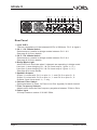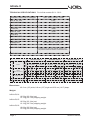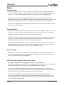
1
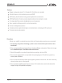
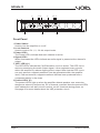
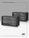
OWNER'S MANUAL
INFINITE QX 4 - QX 6
POWER AMPLIFIERS
OWNER'S MANUAL
INFINITE QX 4 - QX 6
POWER AMPLIFIERS
Infinite X
Infinite X
IMPORTANT
THE PRODUCT REQUIRES
CLASS 2 OUTPUT WIRING.
TO PREVENT ELECTRIC SHOCK, DO NOT
REMOVE TOP OR BOTTOM COVERS.
NO USER SERVICEABLE PARTS INSIDE.
REFER SERVICING TO QUALIFIED
SERVICE PERSONNEL. DISCONNECT
POWER CORD BEFORE REMOVING
REAR PANEL COVER TO ACCESS GAIN
SWITCH.
Shock Hazard - Do Not Enter
Choc Hasard - N*entrent
Schocke Hazard - Test Nicht
Betrete
Urto Hazard - Do Non Entrano
WARNING
TO REDUCE THE RISK OF ELECTRIC
SHOCK, DO NOT EXPOSE THIS
EQUIPMENT TO RAIN OR MOISTURE!
Magnetic Field
CAUTION: Do not locate sensitive high-gain equipment such as preamplifiers or tape decks
directly above or below this unit. Because this amplifier has a high power density, it has a
strong magnetic field which can induce hum into unshielded devices that are located nearby.
This field is strongest just above and below the unit. If an equipment rack is used, we
recommend locating the amplifier(s) at the bottom of the rack and the preamplifier or other
sensitive equipment at the top.
The lightning bolt triangle is
used alert the user to the risk
of electric shock
Page 3
The exclamation point triangle is used
to alert the user to important operating
and/or maintenance instructions.
Printed on
recycled paper.
Reference Manual
Infinite X
Features
Rugged, touring grade chassis. E.I.A. Standard 2U 19" (48.3cm) rack-mountable.
Ultra high frequency switch modulated power supply (SMP).
'VSP' Velocity Sense Protection circuitry protects speakers from over excursion.
'CEP' Clip Elimination Protection prevents clipped waveforms from reaching the outputs.
Four independent filter networks with adjustable crossover frequencies.
Stereo, parallel and bridge operation for optimal load matching.
Soft start for loudspeaker protection.
Complete protection against shorted outputs, mismatched loads, overheating and DC input/output.
Three year warranty and guarantee.
Precautions
Although your amplifier is protected from external faults, the following safety precautions are recommended:
1. Do not change the position of the bridge - parallel - stereo switch until the input levels have been
turned down.
2. There are important differences between Stereo, Parallel and Bridge mode operation. Please refer to page
8 for a detailed description of the different modes and there uses.
3. Switch off the amplifier or turn down the inputs before connecting to the in/out XLR's.
4. Do not short the ground lead of an output cable to the input signal ground. This will form a ground loop
and may cause oscillations.
5. Do not connect both channels positive outputs together in parallel or stereo modes. And never connect any
channels positive output to chassis ground.
6. Do not operate the amplifier from AC mains in excess of 10% variation above or below the selected line
voltage, and only at the specified line frequency.
Page 4
Reference Manual
Infinite X
34 5
2
1
2
1
ON -18
Power
oo
0
oo
0
-6
34 5
2
3
0
L
4
1
P
ON -18
oo
2
0
oo
0
-6
0
L
P
2
Infinite QX 4
1
6
6
Front Panel
1.Power Switch
Used to turn the amplifier on or off.
2.Level Controls
Used to control CH 1, 2, 3 & 4's output levels.
3.Power LED's
The Power LED's indicate that each channel is active.
4.Signal LED's
When illuminated the LEDs indicate an audio signal is present at the channel's
output.
5.'CEP' LED's (L)
The CEP LED's indicate the Clip Elimination circuit is active. The CEP circuit
works by examining the audio output signal, it then regulates many circuits
within the amplifier to reduce clipping at the output. Note that the CEP circuit
can only prevent a clipped waveform from be generated within the amplifier
itself, it cannot remove a clipped waveform that has been produced from a
component earlier in the chain.
6.Protect LED's (P)
The protect LED's light up when the amplifier detects speaker over excursion,
dangerous subsonic frequencies, DC or thermal overload. Note the protect LED's
also indicate the soft start circuit is active, so will illuminate during power on.
See page 8 for more details about the VSP protection circuit.
Page 5
Reference Manual
Infinite X
3 4 6
CH 4 - CH 3
Stereo
Bridge
Lo Pass
7
Hi Pass
300Hz
1k
2k
300Hz
6
1k
2k
3.5k
Bypass
Parallel
Bridge Mode
Out 1 : Pin 1+ : sig + Out 3 : Pin 1+ : sig +
Pin 2+ : sig Pin 2+ : sig -
100
Hz
5kHz
Lo Pass
Hi Pass
CH 2 - CH 1
Stereo
Bridge
Lo Pass
7
Hi Pass
1k
300Hz
2k
3.5k
100
Hz
70Hz
CH 4
XOVER
2 4 6
70Hz
5kHz
300Hz
6
1k
2k
3.5k
Bypass
Parallel
100
Hz
Bypass
CH 3
XOVER
Outputs
5kHz
Hi Pass
Serial No.
230V AC 50Hz
70Hz
5kHz
Inputs
Bridge
Input
Lo Pass
3.5k
100
Hz
70Hz
CH 2
XOVER
8
Bypass
CH 1
XOVER
Bridge
Input
Out 1 : Pin 1+ : ch 1 +
Pin 1 - : ch 1 Pin 2+ : ch 2 +
Pin 2 - : ch 2 -
CH 4
CH 3
CH 2
5
CH 1
CH 4
CH 3
CH 2
CH 1
Out 3 : Pin 1+ : ch 3 +
Pin 1 - : ch 3 Pin 2+ : ch 4 +
Pin 2 - : ch 4 -
1
Rear Panel
1.Input XLR's
The input impedance of the balanced XLR's is 20Kohms. Pin 2 is signal +
2.CH 1 - CH 2 Mode Switch
Selects stereo, parallel or bridge modes between CH 1 & 2.
See page 8 for more details.
3.CH 3 - CH 4 Mode Switch
Selects stereo, parallel or bridge modes between CH 3 & 4.
See page 8 for more details.
4.Bridge Mode Light
A blue LED will illuminate when 2 channels are operating in bridge mode.
Use input 1 when bridging CH 1 & CH 2 and output 1 (pins 1+, 2+)
Use input 3 when bridging CH 3 & CH 4 and output 3 (pins 1+, 2+)
See page 8 for more details.
5.Speakon Outputs
Output 1 is wired with CH 1 on pins 1+, 1- and CH 2 on pins 2+, 2-.
Output 3 is wired with CH 3 on pins 1+, 1- and CH 4 on pins 2+, 2-.
Outputs 2 and 4 are wired 1+, 1- only.
6.Channel Filter Switch
Selects between Hi Pass, Lo Pass or no filter (bypass) for each channel.
7.Filter Frequency Selector
Adjusts each channels filter frequency anywhere between 70Hz to 5kHz.
8.Power Input
32 Amp Powercon socket. 230 VAC 50Hz.
Page 6
Reference Manual
Infinite X
TECHNICAL SPECIFICATIONS For Infinite models QX 4 - QX 6
20Hz - 20kHz +0.05 dB / -0.06 dB
FREQUENCY RESPONSE ref.100W@8W
THD ref. 4W, 1KHz
0.02%
S/N 20Hz-20kHz, ref full output
104 dB
20kW balanced
INPUT IMPEDANCE
CROSSTALK
>90dB
CMRR ref. 1KHz
>87dB
SLEW RATE
60V/us
DAMPING FACTOR 1kHz and Below
>400
FILTER SLOPE & TYPE
24dB/oct
CONNECTORS
Linkwitz-Riley
Input: balanced XLR Output: Speakon
COOLING
Variable speed fans
AMPLIFIER PROTECTION
Full short circuit, open circuit, thermal, ultrasonic, and
RF protection, stable into reactive or mismatched loads
VOLTAGE RANGE
Stereo
(Both CH Driven)
Bridge Mode
Infinite QX 4
Infinite QX 5
Infinite QX 6
RMS Output Power per ch
RMS Output Power per ch
RMS Output Power per ch
0.1%THD+N
0.1%THD+N
0.1%THD+N
0.1%THD+N
0.1%THD+N
10Hz-20kHz
Impedance
Mode
230 VAC 50Hz +/- 10%
0.1%THD+N
1kHz
10Hz-20kHz
1kHz
10Hz-20kHz
1kHz
8
400
395
600
595
900
894
4
600
596
1000
997
1200
1195
2
900
894
1500
1496
-------
-------
8
2 x 1200
2 x 1192
2 x 2000
2 x 1994
2 x 2400
2 x 2390
4
2 x 1800
2 x 1788
2 x 3000
2 x 2992
-------
-------
Voltage Gain (8 W)
36.07dBu
37.83dBu
39.59dBu
Maximum Current Draw
all ch - 2 ohms 18.78 Amps
all ch - 2 ohms 31.29 Amps
all ch - 4 ohms 25.03 Amps
Dimensions :
48.3 cm (19") wide, 8.8 cm (3.5") high and 36.8 cm (14.5") deep.
Weight:
Infinite QX 4 :
Infinite QX 5 :
Infinite QX 6 :
Page 7
10.5 Kg (23.1 lbs) net.
12.1 Kg (26.7 lbs) shipping weight.
10.5 Kg (23.1 lbs) net.
12.1 Kg (26.7 lbs) shipping weight.
10.6 Kg (23.3 lbs) net.
12.2 Kg (26.9 lbs) shipping weight.
Reference Manual
Infinite X
Notes
Bridge Mode
To bridge channel 1 and 2 connect to input 1 only and use CH1 speakon output (pins
1+, 2+). To bridge channel 3 and 4 connect to input 3 only and use CH3 speakon output
(pins 1+, 2+). Pin 1+ will be signal positive (+) on output 1 and 3 in bridge mode.
Use channel 1's filter when bridging channels 1 and 2 and channel 3's filter when
bridging channels 3 and 4. Channel 2's filter is not operational when channel 1 and 2 are
bridged and channel 4's filter is not operational when channel 3 and 4 are bridged.
The minimum impedance in bridge mode must be 4 ohms for the Infinite QX 4 and QX 5
and 8 ohms for Infinite QX 6.
Parallel Mode
When input 1 and 2's mode switch is set to parallel, input 1 is linked to input 2. Connect
to input 1 or input 2 and the same signal will output from both CH1 and CH2 outputs.
Each channels level is set with its own front panel level control.
When input 3 and 4's mode switch is set to parallel, input 3 is linked to input 4. Connect
to input 3 or input 4 and the same signal will output from both CH3 and CH4 outputs.
Each channels level is set with its own front panel level control.
Note that parallel operation on Infinite X amplifiers is not like the parallel mode on some
amplifiers that allow you to drive into very low impedances. Parallel mode on Infinite X
series amplifiers makes a pair of inputs receive the same signal.
Stereo Mode
When input 1 and 2's mode switch is set to stereo, input 1 and 2 are not linked and
operate independently. When input 3 and 4's mode switch is set to stereo, input 3 and 4
are not linked and operate independently.
VSP Velocity Sense Protection (limit)
All Infinite X amplifiers are equipped with velocity sensing protection.
The VSP circuit monitors back EMF and will attenuate the output for a very brief period if
the amplifier detects over excursion or potential damage to a speaker.
If very severe overload conditions are detected and speaker failure is imminent, the
amplifier will mute its output for a brief period. Reducing the amplifiers output level will
stop the protection circuit from muting the output in this situation.
Please note that the VSP circuit can only assist with protecting your speakers.
It in no way guarantees complete protection against any component failure and safe
working practices should always be followed with regard to matching amplifier output
levels to speaker input ratings.
Page 8
Reference Manual
Infinite X
Service
This unit has very sophisticated circuitry and should only be serviced by a fully trained
technician.
No user serviceable parts inside
Refer servicing to a qualified technician
Worldwide Service
Service may be obtained from your local authorised service centre. To obtain service,
simply present your sales receipt as proof of purchase along with the defective unit to
an authorised service centre. They will handle the necessary paperwork and repair.
Remember to transport your unit in the original factory packaging.
1. When sending an infinite Series product to an authorised service centre for service,
please write a detailed description of the fault and list any other equipment used in
conjunction with the faulty product. Send the fault description with the faulty product,
do not send it separately.
2. Ensure safe transportation of your unit to the authorised service centre. Ship it in the
original factory packaging if possible.
3. Do not ship the unit in any kind of rack. Ignoring this warning may result in extensive
damage to the unit and the equipment rack. Accessories are not needed. Do not
send the instruction manual, cables or any other hardware.
4. Before returning your faulty product for repair, please remember to get a return
authorisation number from the dealer whom you purchased your product from.
Failure to do so could delay the repair of your product.
Warranty Registration
Please take time to fill out the warranty registration form at the back of this manual and
return it to Void Acoustics.
Environmental
WEEE Mark
If you want to dispose of this product, do not mix with general
household waste. There are separate collection systems for used
electronic products in accordance with legislation under the WEEE
Directive (Directive 2002/96/EC) and is effective only within the
European Union.
This product is Rohs compliant
Page 9
Pb
Reference Manual
Infinite X
LIMITED WARRANTY
THE WARRANTY
For a period of three (3) years from the date of delivery to the original purchaser (as shown
on the original invoice or sales receipt), Void Acoustics (hereinafter "Void") warrants to the
ORIGINAL OWNER of each new Infinite Series product (provided it was purchased at an
Authorised Void Dealer) that it is free of defects in materials and workmanship and that each
product will meet or exceed all factory published specifications for each respective model.
Void agrees to repair or replace (at its discretion) all defective parts at no charge for labour or
materials; subject to following provisions:
WARRANTY VIOLATIONS
Void shall take no responsibility for repair or replacement as specified under this warranty, if
the damaged product has been subject to misuse, accident, neglect or failure to comply with
normal maintenance procedures; or if the serial number has been defaced, altered or
removed. Nor will Void accept responsibility for, or resulting from, improper alterations or
unauthorised parts or repairs. This warranty does not cover any damage to speakers or any
other consequential damage resulting from breach of any written or implied warranty.
VOID WARRANTY PROVISIONS
Void will remedy any defect, regardless of the reason for failure (except as excluded) by
repair, or replacement. Void will remedy the defect and ship the product within a reasonable
time after receipt of the defective product at an Void Authorised Service Centre.
TO OBTAIN WARRANTY SERVICE
In the event that a Void product requires service, the Owner must contact Void or an
Authorised Void Service Centre to receive an R.A.N. (Return Authorisation Number) and
instructions on how to return the product to the Void Authorised Service Centre, or to the
factory. Void (or its Authorised Service Centre) will initiate corrective repairs upon receipt of
the returned product. Please save the original carton and all the packing materials in case
shipping is required. All products being returned to the factory or service centre for repairs
must be shipped prepaid.
If the repairs made by Void or the Void Authorised Service Centre are not satisfactory, the
Owner is instructed to give written notice to Void. If the defect or malfunction remains after a
reasonable amount of attempts by Void to remedy the defect or malfunction, the Owner shall
then have the option to elect either a refund or replacement of said Void product free of
charge. The refund shall be an amount equal to but not greater than the actual purchase
price, not including any taxes, interest, insurance, closing costs and other finance charges
(minus reasonable depreciation on the product). If a refund is necessary, the Owner must
make the defective or malfunctioning product available to Void free and clear of all liens or
other restrictions.
MODIFICATIONS OF EQUIPMENT
Void reserves the right to modify or change equipment (in whole or part) at any time prior to
delivery thereof, in order to include therein electrical or mechanical improvements deemed
appropriate by Void, but without incurring any liability to modify or change any equipment
previously delivered, or to supply new equipment in accordance with any earlier
specifications.
DISCLAIMER OF CONSEQUENTIAL AND INCIDENTAL DAMAGES
YOU, THE OWNER, ARE NOT ENTITLED TO RECOVER FROM VOID ANY INCIDENTAL
DAMAGES RESULTING FROM ANY DEFECT IN THE VOID PRODUCT. THIS INCLUDES
ANY DAMAGE TO ANOTHER PRODUCT OR PRODUCTS RESULTING FROM SUCH A
DEFECT.
WARRANTY ALTERATIONS
No person has the authority to enlarge, amend, or modify this Warranty. This Warranty is not
extended by the length of time which the Owner is deprived of the use of product. Repairs
and replacement parts provided pursuant to the Warranty shall carry only the non-expired
portion of the Warranty.
THIS STATEMENT OF WARRANTY SUPERSEDES ALL OTHERS CONTAINED IN THIS
MANUAL
Technical and design specifications are subject to change without notice
Page 10
Reference Manual
Unit 10B, Dawkins Road Ind Est, Poole, Dorset, BH15 4JD
Tel: +44 (0)844 410 1440 Fax: +44 (0)844 410 1439
Void Acoustics
This warranty in no way affects your statutory rights.
Carriage costs to Void Acoustics will be returned to the
customer if warranty work proves necessary. Packing,
insurance and freight on the return journey will be paid by
Void Acoustics or its authorised dealers.
Do not send goods to Void Acoustics without first obtaining
a return authorisation number.
4. That the product has not suffered damage in transit.
3. That the product has not been modified, disassembled
or tampered with by any person other than Void Acoustics
technical staff.
Tel :
Model
Void Acoustics, Unit 10B, Dawkins Road Ind Est, Poole,
Dorset, BH15 4JD, UK.
Return the product (preferably in its original box) to :
Contact the dealer from whom you purchased the product
and get a return authorisation number.
What to do if your Void product needs repair
Post code :
Suppliers name and address
Serial number
1. This warranty is only valid in the country of purchase.
2. That the product has not been abused or operated in
conjunction with unsuitable or faulty apparatus.
Date of purchase
Warranty Copy
Owner's
This Void Acoustics product is guaranteed against defects
due to faulty materials or workmanship for a period of 3
years from the date of original purchase, subject to the
following restrictions.
Warranty
Void Acoustics
Void Acoustics
Unit 10B
Dawkins Road Ind Est
Poole
Dorset
BH15 4JD
UK
Post code :
Post code :
Tel :
Your name and address
Tel :
Suppliers name and address
Serial number
Date of purchase
Model
Thank you for purchasing this Void product. Please
complete this warranty registration card and cut off this
part and send it to the address overleaf.
Warranty Registration